fiberweld hr - laser mechanisms, inc. fiberweld hr rev a.pdfin, all shipping documentation and a...
TRANSCRIPT

FiberWELD HR ®
Operation Manual

PLMNL0253 REV. A Effective Date: 02/13/17 i FiberWELD® HR Operation Manual
WARNING
WORKING AROUND HIGH-POWERED LASERS CAN BE DANGEROUS
Laser Mechanisms, Inc.’s cutting heads must be operated with the cutting head interlock switch connected. The switch must be CLOSED when the head is properly attached. In the event of a crash and the cutting head becoming dislodged from its normal operating position, the switch must be OPEN. This interlock switch must be connected in a circuit in such a way that it will immediately turn off the laser and stop all machine motion. Check the wiring diagrams for your system.
Serious personal injury and/or equipment damage can occur if the head becomes dislodged and:
The head interlock is not connected properly.
Any interlock in the Laser Mechanisms’ product or laser system is defeated.
Laser Mechanisms, Inc. assumes no responsibility or liability for interlock switches or circuits and all interlocks are the sole responsibility of the purchaser of this head.
It is the responsibility of the integrator or end user to install, connect and activate all interlocks in compliance with the applicable ANSI, CEN, DIN, etc. standard.
All wiring should be done by personnel knowledgeable in electrical wiring and in accordance with the national and local electrical codes.
DISCLAIMER
The information in this manual is subject to change without notice.
Laser Mechanisms, Inc. makes no warranty of any kind with regard to the material in this manual, including but not limited to, the warranties or merchantability and fitness for a particular purpose.
Laser Mechanisms, Inc. shall not be liable for errors contained herein or for incidental or consequential damages in connection with furnishing, performance or use of this product.
Laser Mech® is a registered trademark of Laser Mechanisms, Inc.
Corporate names and trademarks stated herein are the property of their respective companies.
COPYRIGHT
©2017 Laser Mechanisms, Inc. All rights reserved. No part of this publication may be reproduced in any form, or by any means without the prior written permission of Laser Mechanisms, Inc.
PRODUCT WARRANTY
Laser Mechanisms, Inc. warrants this product against defects in material and workmanship for a period of one year from the date of shipment from Laser Mechanisms Inc. or an authorized distributor. During the warranty period, Laser Mechanisms, Inc. will at its option, repair or replace products that prove to be defective.
For all products returned to Laser Mechanisms, Inc. for warranty service the customer must:
Call Laser Mechanisms, Inc. for a Return Material Authorization (RMA) number.
Properly pack the product with the RMA number on the outside of the package. Include in the package all cables and all accessories shipped with the product along with a description of the problem.
Prepay shipping charges to Laser Mechanisms, Inc.
Insure the shipment in case of loss or damage. Laser Mechanisms, Inc. will not accept any liability in case of damage or loss.
Laser Mechanisms, Inc. will pay the shipping charges, duties and taxes for the products returned to Laser Mechanisms, Inc. from outside the United States.
The foregoing warranty will not apply if damage is incurred resulting from improper or inadequate maintenance by the customer, unauthorized modifications or misuse, operation of the product outside its specifications, interlocks not connected properly, improper site preparation, parts or assemblies not supplied by Laser Mechanisms, Inc. or unauthorized repair by non-Laser Mechanisms, Inc. authorized personnel.
For complete warranty information visit our web site at www.lasermech.com.

PLMNL0253 REV. A Effective Date: 02/13/17 ii FiberWELD® HR Operation Manual
INITIAL INSPECTION
Inspect all shipping containers for damage as soon as the device arrives. It is your responsibility, the recipient, to notify the freight company of any damage. The freight company will require you to provide the container that any goods were shipped in, all shipping documentation and a list of all damages. Photographs of the damage are helpful in settling a freight claim.
Do not return damaged goods to the factory without a Return Material Authorization Number (RMA number).
Although it is Laser Mechanisms, Inc.’s intent to insure you are up and running as soon as possible, damage incurred during shipment must be settled with the freight company before arranging for repairs or replacement. No return shipments will be accepted without an RMA number clearly printed on the outside of all shipping containers. Failure to follow this procedure could void any warranty coverage on your head. Call your sales engineer at Laser Mechanisms, Inc. for an RMA number.
Carefully remove the device from its shipping container and all packing material to avoid damage. Save all packaging material, including the sealed, padded pelican case, in the event the head requires shipping or storage.
Check all items received against the packing list to verify that all the items were received.
Please note the product you receive may differ slightly from the illustrations in this manual. While the drawings may differ, the basic procedures described within remain the same.
TERMS USED IN THIS MANUAL
WARNING: The user could be injured if the warning is not followed.
CAUTION: The device or system could be damaged if the caution is not followed.
NOTE: Clarification of a step or steps.
SAFETY
WARNINGS: Follow all warnings in this manual.
SAFETY GLASSES: Everyone in the area where the laser is being used must wear laser safety glasses designed for the laser being used.
SECONDARY REFLECTIONS: Secondary reflections are dangerous; never expose any part of your body to a reflected laser beam.
INTERLOCKS: Interlocks are safety devices and should never be defeated.
ADJUSTMENTS: Always turn off or put the laser in standby before making any adjustments to beam delivery components.
BEAM DUCT: Never open any component of the beam duct while the laser is operating. Always turn the laser off before servicing any beam duct components.
MANUALS: Always read the instruction manuals before attempting to install or make adjustments to any beam delivery component.

PLMNL0253 REV. A Effective Date: 02/13/17 iii FiberWELD® HR Operation Manual
Table of Contents
1 Introduction ........................................................................................................................................................1
2 Mechanical Installation ......................................................................................................................................2 2.1 Mounting ............................................................................................................................................. 2
2.2 Fiber Input ........................................................................................................................................... 2
2.3 Bundling .............................................................................................................................................. 2
2.4 Plumbing – Water Cooling / Cover (Assist) Gas / Purge Gas / Air Knife ............................................ 3
3 Electrical Installation .........................................................................................................................................4 3.1 Machine Interface Connection ............................................................................................................ 4
4 Operation ............................................................................................................................................................5 4.1 Fiber Orientation Adjustment .............................................................................................................. 5
5 FiberWELD® Monitor ..........................................................................................................................................6 5.1 Installation ........................................................................................................................................... 6
5.1.1 Downloading FiberWELD® Monitor Software ...................................................................6
5.1.2 Installing FiberWELD® Monitor Driver ..............................................................................7
5.2 System Requirements ........................................................................................................................ 7
5.3 Connecting .......................................................................................................................................... 7
5.4 Display Screen .................................................................................................................................... 8
5.5 FiberWELD® Monitor Settings ............................................................................................................ 8
5.5.1 Unlock Settings ................................................................................................................9
5.5.2 Aperture ............................................................................................................................9
5.5.3 Upper Assembly ............................................................................................................ 10
5.5.4 Lower Assembly ............................................................................................................ 10
5.5.5 Difference ...................................................................................................................... 10
5.5.6 Presence Threshold ...................................................................................................... 11
5.5.7 Other Setting Controls ................................................................................................... 11
5.5.8 Faults ............................................................................................................................. 12
5.6 FiberWELD® Monitor System Identification Information ................................................................... 13
6 Service.............................................................................................................................................................. 14 6.1 Cleaning Non-Metal Optics ............................................................................................................... 14
6.2 Servicing the Cover Glass ................................................................................................................ 16
6.3 Adjusting the Air Knife Air Stream .................................................................................................... 17
PLMNL0253 REV. A Effective Date: 02/13/17 iv FiberWELD® HR Operation Manual
6.4 Cover Gas Delivery ........................................................................................................................... 18
6.4.1 Cutting the Cover Gas Delivery Tube to Length ........................................................... 18
6.4.2 Adjusting the Cover Gas Delivery ................................................................................. 18
6.4.3 Removing and Replacing the Copper Aperture ............................................................ 19
6.5 Optional Camera Mount .................................................................................................................... 19
6.5.1 Mounting or Removing the Camera Mount ................................................................... 19
6.5.2 Camera Specifications .................................................................................................. 20
6.5.3 Adjusting the Camera Mount ......................................................................................... 21
6.6 Cleaning the Copper Parabolic Collimating Mirror ........................................................................... 21
6.7 Replacing the Copper Parabolic Collimating Mirror .......................................................................... 23
6.8 Cleaning the Copper Parabolic Focusing Mirror ............................................................................... 23
6.9 Replacing the Copper Parabolic Focusing Mirror ............................................................................. 25
6.10 Servicing the Beam Combiner Optic................................................................................................. 25
7 Specifications .................................................................................................................................................. 28
8 Troubleshooting .............................................................................................................................................. 29
9 Appendix A – Coolant Specifications ........................................................................................................... 30
10 Appendix B – Beam Delivery Purging ........................................................................................................... 30
11 Appendix C – Assist Gas Specifications ...................................................................................................... 30
12 Appendix D – Recommended User-Serviceable Parts List ........................................................................ 31
13 Appendix E – Configurations ......................................................................................................................... 33
14 Appendix F – Fiber End Types ...................................................................................................................... 34
PLMNL0253 REV. A Effective Date: 02/13/17 1 FiberWELD® HR Operation Manual
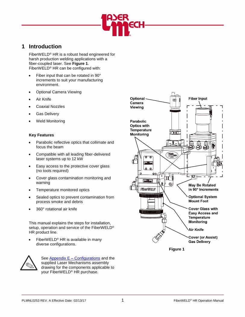
1 Introduction
FiberWELD® HR is a robust head engineered for harsh production welding applications with a fiber-coupled laser. See Figure 1. FiberWELD® HR can be configured with:
Fiber input that can be rotated in 90° increments to suit your manufacturing environment.
Optional Camera Viewing
Air Knife
Coaxial Nozzles
Gas Delivery
Weld Monitoring
Key Features
Parabolic reflective optics that collimate and focus the beam
Compatible with all leading fiber-delivered laser systems up to 12 kW
Easy access to the protective cover glass (no tools required)
Cover glass contamination monitoring and warning
Temperature monitored optics
Sealed optics to prevent contamination from process smoke and debris
360° rotational air knife
This manual explains the steps for installation, setup, operation and service of the FiberWELD® HR product line.
FiberWELD® HR is available in many diverse configurations.
See Appendix E – Configurations and the supplied Laser Mechanisms assembly drawing for the components applicable to your FiberWELD® HR purchase.
Figure 1
PLMNL0253 REV. A Effective Date: 02/13/17 2 FiberWELD® HR Operation Manual
2 Mechanical Installation
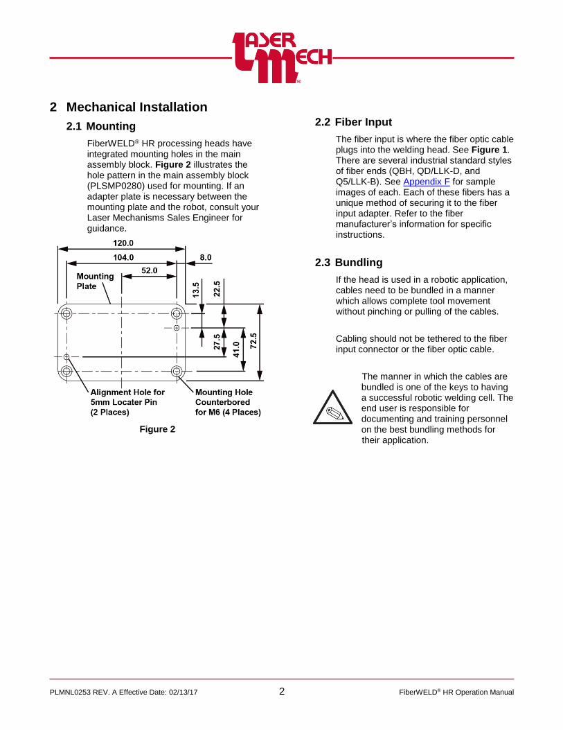
2.1 Mounting
FiberWELD® HR processing heads have integrated mounting holes in the main assembly block. Figure 2 illustrates the hole pattern in the main assembly block (PLSMP0280) used for mounting. If an adapter plate is necessary between the mounting plate and the robot, consult your Laser Mechanisms Sales Engineer for guidance.
Figure 2
2.2 Fiber Input
The fiber input is where the fiber optic cable plugs into the welding head. See Figure 1. There are several industrial standard styles of fiber ends (QBH, QD/LLK-D, and Q5/LLK-B). See Appendix F for sample images of each. Each of these fibers has a unique method of securing it to the fiber input adapter. Refer to the fiber manufacturer’s information for specific instructions.
2.3 Bundling
If the head is used in a robotic application, cables need to be bundled in a manner which allows complete tool movement without pinching or pulling of the cables.
Cabling should not be tethered to the fiber input connector or the fiber optic cable.
The manner in which the cables are bundled is one of the keys to having a successful robotic welding cell. The end user is responsible for documenting and training personnel on the best bundling methods for their application.

PLMNL0253 REV. A Effective Date: 02/13/17 3 FiberWELD® HR Operation Manual
2.4 Plumbing – Water Cooling / Cover (Assist) Gas / Purge Gas / Air Knife
All gas or coolant lines must be suitable for laser applications and are NOT supplied.
For line locations and specifications, see Figure 3.
The water cooling lines require:
o ᴓ6mm OD / ᴓ4mm ID hoses
o 1.5 liter/minute flow rate
o 5 Bar max pressure
o 19-35°C temperature
o Cooling specifications can be found in Appendix A.
The cover (assist) gas line requires:
o ᴓ6mm OD / ᴓ4mm ID hoses
o 10 Bar max pressure
o The supply line must be rated higher than the maximum expected pressure.
o Specifications for cover (assist) gas can be found in Appendix C.
Both purge gas lines require:
o ᴓ6mm OD / ᴓ4mm ID hoses
o Specifications for purge gas can be found in Appendix B.
The purge gas creates positive pressure inside the head to keep out contaminants and requires:
o 1.4 liter/minute flow rate
o 0.3 Bar max pressure
The high pressure (HP) purge gas keeps the area between the lower cover glass and the air knife clean
and requires:
o 0.7 to 2.0 Bar
The air knife requires:
o ᴓ12mm OD / ᴓ10mm ID hoses
o 6.2 Bar max pressure
Figure 3

PLMNL0253 REV. A Effective Date: 02/13/17 4 FiberWELD® HR Operation Manual
3 Electrical Installation
The FiberWELD® HR electrical connections are designed to be simple for end users. See Figure 4.
There are (4) locations where cables must be connected to the head.
There are (2) locations to connect the head to end user equipment.
Figure 4
3.1 Machine Interface Connection
Power: 28V max, 100mA max
It has an M12 thread, 4 pins, and a male connection on the top of the electrical box that is located on the collimator.
The cabling used at this connection is the female end of PLCAB0595 (supplied with the head), or equivalent.
M12 Pin Wire Color Description
1 BRN +24V
2 WHT Interlock
3 BLU Ground
4 BLK Interlock

PLMNL0253 REV. A Effective Date: 02/13/17 5 FiberWELD® HR Operation Manual
4 Operation
4.1 Fiber Orientation Adjustment
Most fiber optic cables are keyed and will only fit into the Fiber Interface Adaptor (FIA) in one orientation. The FIA can be rotated to match the orientation of the fiber coupler and reduce twisting of the fiber optic cable.
To reorient the connector on the FiberWELD® HR (See Figure 5):
1. Loosen, but do not remove, the 4 clamping bolts by 1/4 turn with a 3mm hex key wrench.
2. Rotate the FIA to match the orientation of the fiber optic cable.
It is possible to remove the (4) clamping bolts and the top plate.
The top plate will only mount on the guide pins in one orientation.
If the clamping bolts have not been removed and the top plate has not been rotated, orient the fiber adapter correctly and tighten the (4) clamping bolts.
If the clamping bolts have been removed and the top plate has been rotated, rotate the top plate back into position, reinsert and tighten the (4) clamping bolts.
Figure 5

PLMNL0253 REV. A Effective Date: 02/13/17 6 FiberWELD® HR Operation Manual
5 FiberWELD® Monitor
FiberWELD® Monitor is a very useful tool for use with your FiberWELD® HR head. FiberWELD® Monitor runs on a standard PC and connects to the controller with a USB cable. It provides real time monitoring of head temperatures (electronics, aperture, and copper parabolas) and cover glass presence. See Figure 6.
Figure 6
5.1 Installation
5.1.1 Downloading FiberWELD® Monitor Software
Download the latest copy of the FiberWELD® Monitor software from the FiberWELD® Updates web page:
http://www.lasermech.com/fiberweldupdates.asp
Once the compressed folder is downloaded from the web site it only needs to be decompressed.
1. Right-click on the compressed folder and select Extract All....
2. Follow the on-screen instructions to complete the decompression (extraction) of the compressed files.
The resulting folder will have a single FiberWeldMonitor.exe file, a driver folder, and a folder named FiberWeldMonitor Libs.
It is important that the Libs folder remain at the same location as FiberWELD® Monitor.
The parent folder for these files can be moved and copied as needed. No license key is needed.

PLMNL0253 REV. A Effective Date: 02/13/17 7 FiberWELD® HR Operation Manual
5.1.2 Installing FiberWELD® Monitor Driver
Before operating the FiberWELD® Monitor, the FiberWELD® HR head must be connected to a customer supplied Windows based computer using the included USB cable and powered through a separate 24V source. If the system is connected and is not recognized, install the FDTI CDM drivers using the installer found in the Driver directory of the FiberWELD® Monitor folder.
5.2 System Requirements
Windows 7 or later
Minimum Screen Resolution: 800 x 600
USB Port
5.3 Connecting
To connect a FiberWELD® HR head (see Figure 7):
1. Click on the Port drop down menu in the upper left corner and choose the appropriate port.
2. Click Connect.
The Device Manager also lists the port number of the cable as “USB Serial Port.”
Figure 7
The main screen will appear. See Figure 8.

PLMNL0253 REV. A Effective Date: 02/13/17 8 FiberWELD® HR Operation Manual
5.4 Display Screen
After FiberWELD® Monitor is connected, a series of meters appears. See Figure 8.
The settings are based on temperature and voltage ranges. Each thermometer and volt meter displays the upper and lower limits in small digits, along with the current value and a scale representing the current value.
o If the sensor is within the normal operating range it is displayed in green.
o If the sensor is in a faulted state, the scale is displayed in red.
o If the sensor has recovered from a fault, the scale is displayed in amber.
The left side includes:
o A thermometer for the upper parabola
o A volt meter for ambient scattered light detector
o A thermometer for the upper assembly electronics
The center includes:
o A thermometer for the aperture
o A display for the difference between the copper parabola temperature readings.
The right side includes:
o A message to describe whether the system status is READY, FAULT, or RECOVERED.
o A thermometer for the lower assembly
o A volt meter for cover glass presence and integrity.
o A thermometer for the lower assembly electronics
Figure 8
5.5 FiberWELD® Monitor Settings
The FiberWELD® Monitor software and driver are available for download. See Section 5.1 for details.
This section lists the settings that must be specified before operating FiberWELD® Monitor.
Before adjusting any settings:
The software must be installed on your PC. See Section 5.1 for more details.
The head and control interface must be connected properly. See Section 3.1 for more details.

PLMNL0253 REV. A Effective Date: 02/13/17 9 FiberWELD® HR Operation Manual
5.5.1 Unlock Settings
1. Click the Settings menu in the upper left corner of the Main screen and select Unlock Settings. See Figure 9.
In the pop up that appears, enter the password: weldsetup
Figure 9
5.5.2 Aperture
See Figure 10. 1. Click the Settings menu in the
upper left corner of the Main screen and hover over Aperture.
2. Click Temperature Limit.
Figure 10
3. A dialog box will appear with a
field to enter the new limit. See Figure 11.
The current value and valid range are also displayed.
Figure 11
4. Enter a valid new limit value in the provided field.
5. Click OK to store the value and update the thermometer or meter.
6. If necessary, click Cancel to exit the screen.

PLMNL0253 REV. A Effective Date: 02/13/17 10 FiberWELD® HR Operation Manual
5.5.3 Upper Assembly
See Figure 12. 1. Click the Settings menu in the
upper left corner of the Main screen and hover over Upper Assembly.
2. Click Temperature Limit, Ambient Voltage Limit, or Electronics Temperature Limit, as desired.
For more details on Presence Threshold, see Section 5.5.6.
Figure 12
3. Perform steps 3 to 6 in Section 5.5.2.
5.5.4 Lower Assembly
See Figure 13. 1. Click the Settings menu in the
upper left corner of the Main screen and hover over Lower Assembly.
2. Click Temperature Limit, Cover Glass Voltage Limit, or Electronics Temperature Limit, as desired.
For more details on Presence Threshold, see Section 5.5.6.
Figure 13
3. Perform steps 3 to 6 in Section 5.5.2.
5.5.5 Difference
See Figure 14. 1. Click the Settings menu in the
upper left corner of the Main screen and hover over Difference.
2. Click Parabola Temperature.
Figure 14
3. Perform steps 3 to 6 in Section 5.5.2.

PLMNL0253 REV. A Effective Date: 02/13/17 11 FiberWELD® HR Operation Manual
5.5.6 Presence Threshold
The Presence Threshold is used to calibrate the copper parabola presence detectors. Use the following procedure for values other than the factory settings. 1. Click Presence Threshold in the
desired assembly submenu.
The Difference box in the center of the Main screen will change to display the Presence value of the specified parabola. See Figure 15.
The value on the left indicates the minimum observed value and the value on the right indicates the maximum observed value.
Figure 15
2. Wait several seconds for a series of readings to accumulate.
3. Perform steps 3 to 6 in Section 5.4.2, and enter a new value that is approximately 100 less than the maximum observed value.
To determine a more precise presence threshold, perform the procedure in this section while servicing the copper parabola(s). See Section 6. Enter a value halfway between the reading when the parabola is removed and the reading when it is fully inserted.
5.5.7 Other Setting Controls
There are (2) other options to choose in the Settings menu (see Figure 16).
Clicking Use Defaults restores all of the settings to the defaults.
If fault condition(s) exist and are resolved, clicking Clear Resolved Faults resets FiberWELD® Monitor so it is ready for operation again.
Figure 16

PLMNL0253 REV. A Effective Date: 02/13/17 12 FiberWELD® HR Operation Manual
5.5.8 Faults
A fault occurs whenever a thermometer or volt meter reading is outside the allowed range.
The system status message will display FAULT. See Figure 17.
Figure 17
Click on the arrow to the right of the FAULT indicator to display a list of faults present in the system. See Figure 18.
o Active faults are identified using a red indicator.
o Recovered faults are identified using an amber indicator.
Figure 18
Once all fault conditions are cleared, the indicator will change states to RECOVERED. See Figure 19.
o The system is ready while in this state, but the fault list is still available to advise you of previous faults.
o It is often helpful with troubleshooting to record the faults, for example using the Print Screen command.
Figure 19
To acknowledge the fault(s) and return the displayed state to READY, click on the arrow to display the fault list and select “Clear Resolved Faults”. See Figure 19.

PLMNL0253 REV. A Effective Date: 02/13/17 13 FiberWELD® HR Operation Manual
5.6 FiberWELD® Monitor System Identification Information
The hardware and interface are specific to your system. So, version and serial numbers are critical in order for Laser Mechanisms to provide support.
To display system information:
1. Click the Display menu in the upper left corner of the Main screen and select About FiberWELD®… See Figure 20.
Figure 20 2. Click on the View Hardware
Information drop down menu in the pop up box that appears and the image shown in Figure 21 will appear.
Figure 21
3. Click on the appropriate line to view the identifying information for the desired item.
4. Repeat steps 2 and 3 as needed. 5. Click OK to exit the About
FiberWELD® screen.

PLMNL0253 REV. A Effective Date: 02/13/17 14 FiberWELD® HR Operation Manual
6 Service
Regular maintenance is required for the FiberWELD® HR Head. The operating environment has a critical impact on the frequency of maintenance procedures. Consult your Laser Mechanisms Sales Engineer for guidance.
6.1 Cleaning Non-Metal Optics
Optics are very sensitive to dust and debris. It is extremely important to take every possible precaution to ensure the optics remain pristine.
Clean optics in a dust free air-conditioned room.
Before opening any part of the head, clean off the dust and/or process debris using an exterior cleaning towel (PLTLS0023) or equivalent.
ALWAYS handle optics by their edges, never touch the optical surfaces.
ALWAYS wear powder free gloves or finger cots when handling optics and optic holders.
Inspect the optics with high power illumination, such as Laser Mechanisms pen light (PLTLS0021) under 2X magnification.
The following instructions are only a guide. Always follow cleaning instructions supplied by optics manufacturers.
If installing a new optic, inspection and cleaning are still recommended.
Laser Mechanisms Inc. cannot be held responsible for any damage to optics resulting from improper cleaning or handling.
1. Wash hands with soap to remove all oils, and then put on powder free gloves or finger cots.
2. If necessary, remove the optic(s) according to the appropriate section of this document.
3. Hold the optic by the edge and inspect it.
If you see any scratches or pits, replace the optic.
4. Hold the optic by its edges and blow any dust off each side with low-pressure dry nitrogen (2 to 5 PSI) or air from a blow bulb.
DO NOT USE AN AIR COMPRESSOR.
5. Secure the optic by its edge with the curved side facing up.
A fixture may be helpful. Consult your Laser Mechanisms Sales Engineer for assistance.
6. Fold a clean lens tissue (PLOCK0014 – Texwipe Absorband Wipes – or equivalent) so there are several layers and soak it with a non-sterile solution of 70% isopropyl alcohol/30% USP purified water pre-filtered through a 0.2 micron filter (Texwipe TX167 or equivalent).
7. With the soaked lens tissue gently scrub the optic with a circular motion, then slowly wipe in one direction.
8. Turn the optic over (flat side facing up).
9. Using a new lens tissue, repeat steps 6 and 7.
10. Inspect the optic.
If you see any scratches, replace the optic and return to step 3.
If you see any debris, streaks, or cloudiness, proceed to step 11.
If the optic is completely clean, proceed to step 18.

PLMNL0253 REV. A Effective Date: 02/13/17 15 FiberWELD® HR Operation Manual
11. Secure the optic by its edge with the curved side facing up.
12. Fold a clean lens tissue so there are several layers and soak it with isopropanol.
Isopropanol is also known as 2-Propanol or UN1219.
Chemical Abstract Service Registry Number (CASRN) – 67-63-0
Chemical formula – [(CH3)2CHOH]
13. With the soaked lens tissue gently scrub the optic with a circular motion, then slowly wipe in one direction.
14. Turn the optic over (flat side facing up).
15. Using a clean lens tissue, repeat steps 12 and 13.
16. Hold the optic by its edges and blow any dust off each side with low-pressure dry nitrogen (2 to 5 PSI) or air from a blow bulb.
17. Inspect the optic(s).
If you see any scratches, replace the optic and return to step 3.
If you see any debris, streaks, or cloudiness repeat steps 11 to 17 using acetone.
o Acetone is also known as UN1090.
Chemical Abstract Service Registry Number (CASRN) – 67-64-1
Chemical formula – (CH3COCH3)
o Acetone is especially helpful with eliminating haze on cover glasses.
o If using acetone, proceed slowly enough so that the liquid has time to evaporate.
o Lint free cotton swabs (PLOCK0005 – Texwipe 6 inch swabs, or equivalent) may be helpful to remove concentrated contaminants.
If the optic is completely clean, proceed to step 18.
18. Reassemble the optic according to the appropriate section of this document.
Recommended best practices include:
o Blow any dust, lint, debris, etc. off the seals and rings using low-pressure dry nitrogen (2 to 5 PSI) or air from a blow bulb.
o Gently shake the assembled optic near your ear to verify no components are loose.
o Tighten any components as necessary.
o Before reinstalling, inspect the assembled optic again to verify it is clean and unscratched.
o If the optic is not going to be reinstalled immediately, cover it with painter’s tape or equivalent to keep out contaminants.
Take care no adhesive gets on the optic surface.

PLMNL0253 REV. A Effective Date: 02/13/17 16 FiberWELD® HR Operation Manual
6.2 Servicing the Cover Glass
Before opening any part of the head, clean off the dust and/or process debris using an exterior cleaning towel (PLTLS0023) or equivalent.
The cover glass is located next to the input fittings for the air knife, high pressure purge gas and cover gas. See Figure 22.
The cover glass can be changed while the head is mounted on the robot.
Always wear powder free gloves or finger cots when handling optics and optics holders.
1. Release the cover glass door by
squeezing the front of the door with the lever tab. See Figure 22.
Figure 22
2. Swing the cover glass door open by
pulling it. See Figure 23.
Figure 23
For steps 3 to 9 see Figure 24.
Figure 24
3. Grasp the handle on the cover glass cartridge and pull straight out to remove the cartridge from the head.
4. Close the sealed cover glass door during service to keep contaminants out.
PLMNL0253 REV. A Effective Date: 02/13/17 17 FiberWELD® HR Operation Manual
5. Remove the cover glass from the
cartridge by applying pressure with your fingers to the surface of the cover glass, on the side opposite the seal ring.
The seal ring and cover glass will pop out.
Save the seal ring.
6. Inspect the cover glass for damage. Then either:
Clean it according to Section 6.1
OR
Replace it according to steps 7 and 8.
7. Install a cleaned or new cover glass by placing it into the cover glass cartridge.
8. Press the seal ring into the holder to retain the cover slide.
The seal is bi-directional, so it can be inserted in either direction.
Replace the existing seal (PLMSR0032) with a new one if it appears damaged.
9. Open the cover glass door.
10. Push the cover glass cartridge into the main body.
The alignment notch MUST match Figure 24.
11. Test for freedom of motion by pushing and releasing the cartridge.
It should move freely in and out under the pressure you can apply using your thumb. Close the cover glass door.
Verify the door is latched securely.
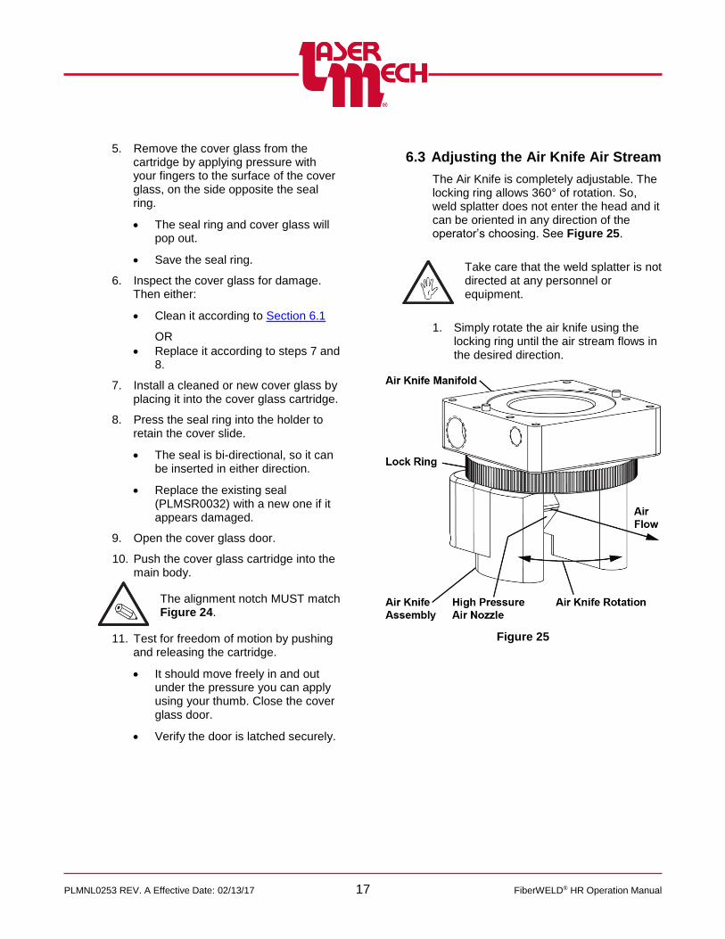
6.3 Adjusting the Air Knife Air Stream
The Air Knife is completely adjustable. The locking ring allows 360° of rotation. So, weld splatter does not enter the head and it can be oriented in any direction of the operator’s choosing. See Figure 25.
Take care that the weld splatter is not directed at any personnel or equipment.
1. Simply rotate the air knife using the locking ring until the air stream flows in the desired direction.
Figure 25

PLMNL0253 REV. A Effective Date: 02/13/17 18 FiberWELD® HR Operation Manual
6.4 Cover Gas Delivery
6.4.1 Cutting the Cover Gas Delivery Tube to Length
The copper tubing used to locate the cover gas delivery nozzle must be customized for your application.
To locate the cover gas delivery nozzle (see Figure 26):
1. Secure the copper tubing in the compression fitting located just below the locking ring.
2. Bend and cut the copper tubing so that the nozzle is located as needed for your application.
3. Insert the copper tubing into the press fit nozzle.
Figure 26
6.4.2 Adjusting the Cover Gas Delivery
The cross flow jet is completely adjustable. The locking ring allows 360° of rotation so the gas is delivered exactly to the desired location. See Figure 26.
Take care that the weld splatter is not directed at any personnel or equipment.
1. Simply rotate the cross flow jet using the locking ring until the nozzle points the gas stream flow in the desired direction.

PLMNL0253 REV. A Effective Date: 02/13/17 19 FiberWELD® HR Operation Manual
6.4.3 Removing and Replacing the
Copper Aperture
The copper aperture assists in keeping the welding head clear of debris. It provides a barrier against weld splatter entering the FiberWELD® HR head.
See Figure 27.
To remove the copper aperture:
1. Unthread and remove the copper aperture from the aperture adapter or other mating component.
Figure 27
To replace the copper aperture:
2. Thread the copper aperture onto the aperture adapter or other mating component.
6.5 Optional Camera Mount
NOTE: NO CAMERA IS INCLUDED WITH THE LASER MECHANISMS CAMERA MOUNT.
THE CAMERA (PLCAM0002) IS SOLD SEPARATELY.
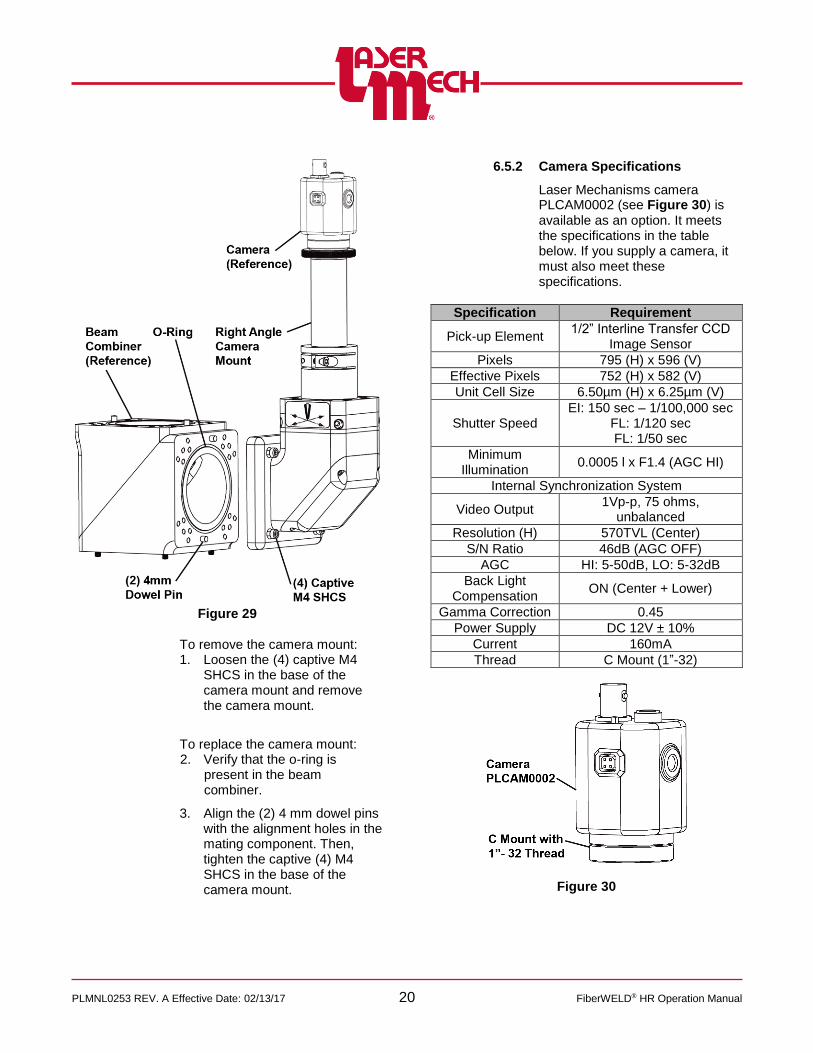
6.5.1 Mounting or Removing the
Camera Mount
The camera mount is oriented using (2) 4mm diameter dowel pins and secured using (4) captive M4 SCHS. A sample straight connection is shown in Figure 28. A sample right angle connection is shown in Figure 29.
Figure 28
PLMNL0253 REV. A Effective Date: 02/13/17 20 FiberWELD® HR Operation Manual
Figure 29
To remove the camera mount: 1. Loosen the (4) captive M4
SHCS in the base of the camera mount and remove the camera mount.
To replace the camera mount: 2. Verify that the o-ring is
present in the beam combiner.
3. Align the (2) 4 mm dowel pins with the alignment holes in the mating component. Then, tighten the captive (4) M4 SHCS in the base of the camera mount.
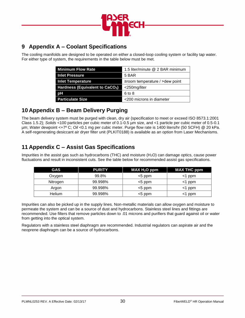
6.5.2 Camera Specifications
Laser Mechanisms camera PLCAM0002 (see Figure 30) is available as an option. It meets the specifications in the table below. If you supply a camera, it must also meet these specifications.
Specification Requirement
Pick-up Element 1/2” Interline Transfer CCD
Image Sensor
Pixels 795 (H) x 596 (V)
Effective Pixels 752 (H) x 582 (V)
Unit Cell Size 6.50µm (H) x 6.25µm (V)
Shutter Speed EI: 150 sec – 1/100,000 sec
FL: 1/120 sec FL: 1/50 sec
Minimum Illumination
0.0005 l x F1.4 (AGC HI)
Internal Synchronization System
Video Output 1Vp-p, 75 ohms,
unbalanced
Resolution (H) 570TVL (Center)
S/N Ratio 46dB (AGC OFF)
AGC HI: 5-50dB, LO: 5-32dB
Back Light Compensation
ON (Center + Lower)
Gamma Correction 0.45
Power Supply DC 12V ± 10%
Current 160mA
Thread C Mount (1”-32)
Figure 30

PLMNL0253 REV. A Effective Date: 02/13/17 21 FiberWELD® HR Operation Manual
6.5.3 Adjusting the Camera Mount
The viewing system is usually adjusted after laser focus position is found and the head is located in the proper laser focus position above the work piece. The method to adjust the straight and right angle camera mounts is the same. An example of the straight camera mount is shown in Figure 31.
Figure 31
For steps 1 to 4, see Figure 31.
Setting Viewing Image Focus
1. Use a 3mm hex wrench to loosen the path enclosure tube locking screw.
2. Adjust the path enclosure tube by sliding it until the image becomes clear.
3. Once the viewing image focus position is properly set, tighten the path enclosure tube locking screw.
Adjusting Position
The position of the viewing system is adjusted using the X-Y adjustment screws on the camera mount.
4. Use a 1/8-inch hex wrench to
loosen or tighten the (2) X-Y adjustment screws until the image is centered on the screen.
6.6 Cleaning the Copper Parabolic Collimating Mirror
Perform the instructions in this section ONLY if there is a problem with the mirror.
Before opening any part of the head, clean off the dust and/or process debris using an exterior cleaning towel (PLTLS0023) or equivalent.
1. Remove the fiber according to Section 2.2.
2. Unplug all cables and cooling lines from the head.
3. Take the entire FiberWELD® HR head to a clean area.
For steps 4 to 6, see Figure 32.
4. Loosen, but do not remove the (4) captive M4 SHCS securing the parabolic spacer cap to the parabolic spacer block.

PLMNL0253 REV. A Effective Date: 02/13/17 22 FiberWELD® HR Operation Manual
5. CAREFULLY, pull the parabolic
spacer cap straight out to remove it.
Take care not to damage the sides of the copper parabolic collimating mirror by contacting the parabolic spacer block.
Figure 32
Now is also a good time to check the water input or output fittings (PLFTG0104). If necessary, unthread the old fitting and thread in a new one.
6. Inspect the copper parabolic collimating mirror and either:
Clean it (proceed to step 7).
OR
Replace it (proceed to Section 6.7).
Optics are very sensitive to dust and debris. It is extremely important to take every possible precaution to ensure the optics remain pristine.
Clean optics in a dust free air-conditioned room.
Before opening any part of the head, clean off the dust and/or process debris using an exterior cleaning towel (PLTLS0023) or equivalent.
ALWAYS handle optics by their edges, never touch the optical surfaces.
ALWAYS wear powder free gloves or finger cots when handling optics and optic holders.
Inspect the optics with high power illumination, such as Laser Mechanisms pen light (PLTLS0021) under 2X magnification.
7. Hold the optic by its edges and blow any dust or lint particles off with low-pressure dry nitrogen (2 to 5 psi) or air from a blow bulb.
NEVER USE SHOP AIR BECAUSE IT CAN CONTAIN OIL AND WATER.
If this does not remove all the contamination, continue to step 8.
8. Lay a piece of clean lens tissue on the surface of the optic. With an eyedropper squeeze a few drops of reagent grade acetone on the lens tissue wetting the complete area of the optic.
9. Without lifting the dampened lens tissue, drag the tissue across the optic just fast enough so the acetone evaporates behind the tissue.
If it is done correctly there will be no streaks left on the optic.
If steps 7 to 9 do not remove all contamination, proceed to Section 6.7 to replace the copper parabolic collimating mirror.

PLMNL0253 REV. A Effective Date: 02/13/17 23 FiberWELD® HR Operation Manual
6.7 Replacing the Copper Parabolic Collimating Mirror
Perform the instructions in this section ONLY if there is a problem with the mirror.
Before opening any part of the head, clean off the dust and/or process debris using an exterior cleaning towel (PLTLS0023) or equivalent.
1. Remove the parabolic spacer cap and copper parabolic collimating mirror according to Section 6.6.
For steps 2 to 8, see Figure 33.
2. Remove the M6 SHCS and serrated washer securing the spacer cap to the copper parabolic collimating mirror.
3. Remove the copper parabolic collimating mirror, but keep the M6 SHCS and serrated washer.
4. Align a new copper parabolic collimating mirror so:
The M6 threaded hole in the center is in line with the M6 hole in the parabolic spacer cap.
The (2) alignment holes are in line properly with the (2) keyed alignment pins in the parabolic spacer cap.
5. Insert and tighten the M6 SHCS and M6 serrated washer.
6. Align the parabolic spacer cap and copper parabolic collimating mirror so the (4) captive M4 SHCS are in line with the (4) M4 threaded holes in the parabolic spacer block.
7. CAREFULLY, insert the parabolic spacer cap and copper parabolic collimating mirror straight into the parabolic spacer block.
Take care not to damage the sides of the copper parabolic collimating mirror by contacting the parabolic spacer block.
8. Tighten the (4) captive M4 SHCS.
Figure 33
6.8 Cleaning the Copper Parabolic Focusing Mirror
Perform the instructions in this section ONLY if there is a problem with the mirror.
Before opening any part of the head, clean off the dust and/or process debris using an exterior cleaning towel (PLTLS0023) or equivalent.
1. Remove the fiber according to Section 2.2.
2. Unplug all cables and cooling lines from the head.
3. Take the entire FiberWELD® HR head to a clean area.

PLMNL0253 REV. A Effective Date: 02/13/17 24 FiberWELD® HR Operation Manual
For steps 4 to 6, see Figure 34.
4. Loosen, but do not remove the (4) captive M4 SHCS securing the parabolic spacer cap to the parabolic spacer block.
5. CAREFULLY, pull the parabolic spacer cap straight out to remove it.
Take care not to damage the sides of the copper parabolic focusing mirror by contacting the parabolic spacer block.
Figure 34
Now is also a good time to check the water input or output fittings (PLFTG0104). If necessary, unthread the old fitting and thread in a new one.
6. Inspect the copper parabolic focusing mirror and either:
Clean it (proceed to step 7).
OR
Replace it (proceed to Section 6.9).
Optics are very sensitive to dust and debris. It is extremely important to take every possible precaution to ensure the optics remain pristine.
Clean optics in a dust free air-conditioned room.
Before opening any part of the head, clean off the dust and/or process debris using an exterior cleaning towel (PLTLS0023) or equivalent.
ALWAYS handle optics by their edges, never touch the optical surfaces.
ALWAYS wear powder free gloves or finger cots when handling optics and optic holders.
Inspect the optics with high power illumination, such as Laser Mechanisms pen light (PLTLS0021) under 2X magnification.
7. Hold the optic by its edges and blow any dust or lint particles off with low-pressure dry nitrogen (2 to 5 psi) or air from a blow bulb.
NEVER USE SHOP AIR BECAUSE IT CAN CONTAIN OIL AND WATER.
If this does not remove all the contamination, continue to step 8.
8. Lay a piece of clean lens tissue on the surface of the optic. With an eyedropper squeeze a few drops of reagent grade acetone on the lens tissue wetting the complete area of the optic.
9. Without lifting the dampened lens tissue, drag the tissue across the optic just fast enough so the acetone evaporates behind the tissue.
If it is done correctly there will be no streaks left on the optic.
If steps 7 to 9 do not remove all contamination, proceed to Section 6.9 to replace the copper parabolic focusing mirror.

PLMNL0253 REV. A Effective Date: 02/13/17 25 FiberWELD® HR Operation Manual
6.9 Replacing the Copper Parabolic Focusing Mirror
Perform the instructions in this section ONLY if there is a problem with the mirror.
Before opening any part of the head, clean off the dust and/or process debris using an exterior cleaning towel (PLTLS0023) or equivalent.
1. Remove the parabolic spacer cap and copper parabolic focusing mirror according to Section 6.8.
For steps 2 to 8, see Figure 35.
2. Remove the M6 SHCS and serrated washer securing the spacer cap to the copper parabolic focusing mirror.
3. Remove the copper parabolic focusing mirror, but keep the M6 SHCS and serrated washer.
4. Align a new copper parabolic focusing mirror so:
The M6 threaded hole in the center is in line with the M6 hole in the parabolic spacer cap.
The (2) alignment holes are in line properly with the (2) keyed alignment pins in the parabolic spacer cap.
5. Insert and tighten the M6 SHCS and M6 serrated washer.
6. Align the parabolic spacer cap and copper parabolic focusing mirror so the (4) captive M4 SHCS are in line with the (4) M4 threaded holes in the parabolic spacer block.
7. CAREFULLY, insert the parabolic spacer cap and copper parabolic focusing mirror straight into the parabolic spacer block.
Take care not to damage the sides of the copper parabolic focusing mirror by contacting the parabolic spacer block.
8. Tighten the (4) captive M4 SHCS.
Figure 35
6.10 Servicing the Beam Combiner Optic
The location of the beam combiner mirror depends on the configuration of the head. If you need assistance accessing the beam combiner mirror, contact your Laser Mechanisms Sales Engineer.
The beam combiner mirror is located in the fixed bender. See Figure 36 and Figure 37.
Before opening any part of the head, clean off the dust and/or process debris using an exterior cleaning towel (PLTLS0023) or equivalent.
Always wear powder free gloves or finger cots when handling optics and optic holders.

PLMNL0253 REV. A Effective Date: 02/13/17 26 FiberWELD® HR Operation Manual
1. Remove the fiber according to Section 2.2.
2. Unplug all cables and cooling lines from the head.
3. Take the entire FiberWELD® HR head to a clean area.
For steps 4 to 8, see Figure 36.
4. Remove the copper parabolic collimating mirror according to Section 6.6.
Take care not to damage the sides of the copper parabolic collimating mirror by contacting the parabolic spacer block.
Store the parabolic spacer cap and copper parabolic collimating mirror in a location where they will not be contaminated by dirt and debris.
5. Loosen, but do not remove the (4) captive M4 SHCS securing the parabolic spacer block to the optional system foot mount or fixed bender.
6. Remove the parabolic spacer block and fiber interface adapter together past the alignment pins on the optional system mount foot or fixed bender.
7. If necessary, loosen, but do not remove the (4) captive M4 SHCS securing the optional system foot mount to the fixed bender.
8. If necessary, remove the optional system foot mount.
Figure 36
The beam combiner block has (2) components. The fixed bender body is the base and includes a mirror. The fixed bender combiner cap is the upper mating component.
For steps 9 to 18, see Figure 37.
9. Turn the head over so the beam combiner mirror is above the fixed bender body.
10. Loosen, but do not remove, the (4) captive M4 SHCS that secure the fixed bender combiner cap of the beam combiner to the fixed bender body. Then, remove the fixed bender combiner cap.
11. Loosen the (4) 4 mm shoulder bolts that secure the mirror to the fixed bender body. Remove the (4) shoulder bolts, (4) compression springs, and (2) mirror mount tabs.
12. Remove the optic, and clean it according to Section 6.1
13. Verify that the seal is present in the fixed bender body.

PLMNL0253 REV. A Effective Date: 02/13/17 27 FiberWELD® HR Operation Manual
14. Using care, place the cleaned or new
optic (if the optic was not clean after step13) in the fixed bender body.
The orientation arrow MUST point toward the fixed bender body, as shown in Figure 37.
15. Align the mirror mount tabs, compression springs, and shoulder bolts so they are in-line with the M4 threaded holes in the fixed bender body.
16. Tighten the M4 shoulder bolts.
17. Align the (4) captive M4 SHCS in the fixed bender combiner cap with the M4 threaded holes in the fixed bender body.
18. Tighten the (4) captive M4 SHCS.
Figure 37
For steps 19 to 23, see Figure 36.
19. Turn the head over so the beam combiner mirror is below the fixed bender body.
20. If necessary, align the (4) captive M4 SHCS in the optional system foot mount with the M4 threaded holes in the fixed bender body.
21. If necessary, tighten the (4) captive M4 SHCS.
22. Align the (4) captive M4 SHCS in the spacer block with the M4 threaded holes in the optional system mount foot or the fixed bender.
23. Tighten the (4) captive M4 SHCS.
24. Install the parabolic spacer cap and copper parabolic collimating mirror according to Section 6.6.
25. Connect all cables and lines removed in step 2.
26. Reinstall the fiber according to Section 2.2.

PLMNL0253 REV. A Effective Date: 02/13/17 28 FiberWELD® HR Operation Manual
7 Specifications
WELDING HEAD
Power Rating ............................................................................................................................ up to 12 kW
Parabolic Focusing Mirror (Effective Focal Length) ................................ 250, 300, 350, 400, 450, 600 mm
Cover Gas Pressure ......................................................................................................... 10 Bar Maximum
Purge Gas Pressure ........................................................................................................ 0.3 Bar Maximum
High Pressure Purge Gas Pressure ................................................................................................. 2.0 Bar
Air Knife Pressure ............................................................................................................................ 6.2 Bar
Gas ................................................. Air Knife-12mm (G3/8 Thread), Purge and Assist-6mm (G1/8 Thread)
Water Ports ................................................................................................................... 6mm (G1/8 Thread)
Weight .................................................................................................................. Configuration Dependent
COLLIMATOR
Parabolic Collimating Mirror (Effective Focal Length) ............................................. 100, 150, 175, 200 mm
Fiber Socket (Others Available On Request) .................................................. QBH, QD/LLK-D, Q5/LLK-B
Specifications are subject to change without notice.
* The actual weight depends on the configuration.

PLMNL0253 REV. A Effective Date: 02/13/17 29 FiberWELD® HR Operation Manual
8 Troubleshooting
Faults indicated by the interlock output are resolved automatically when the error condition(s) are resolved.
Faults indicated by the FiberWELD® Monitor software are cleared automatically when the error condition is resolved and fault conditions are both latched and indicated in a list on the monitor software.
SYMPTOM CAUSE REMEDY
Interlock is not satisfied
Power is turned off to the machine interface.
Check power and all connections to the machine interface and sensor connections.
One or more of the copper parabolas is not installed.
Verify that all of the copper parabolas are installed in the FiberWELD® HR.
The presence threshold setting for the specified parabola is too high. The setting is adjustable to suit the customer's needs. Redefine it as necessary.
The cover glass door is open. Verify that the door is not open. Close if necessary.
The cover glass has reached the maximum signal threshold.
Check the cover glass for debris or damage. Clean or replace as necessary.
The settings for maximum expected signal may be out of range. These settings are adjustable to suit the customer’s need. Redefine it as necessary.
A copper parabola has reached its temperature limit.
Check the specified copper parabola for debris or damage. Clean or replace as necessary.
The settings for maximum operating temperature may be out of range. These settings are adjustable to suit the customer’s needs. Redefine them as necessary.
The temperature of the control electronics is too hot.
This error may occur if ambient temperatures are near the maximum threshold. It is probably impossible to recover from this error if the control unit is damaged.
The difference between parabola temperature sensor readings is out of range.
Either the upper or lower copper parabola is starting to show signs of degradation. Clean or replace as necessary.
The settings for parabola temperature difference may be out of range. These settings are adjustable to suit the customer’s needs. Redefine them as necessary.
The cover glass has reached its temperature limit.
Check the cover glass for debris or damage. Clean or replace as necessary.
The setting for maximum detector voltage may be out of range. The setting is adjustable to suit the customer’s needs. Redefine it as necessary.
A cable is broken or unplugged.
Verify that all of the sensor cables are plugged in and undamaged. Plug in or replace as necessary.
No communication with FiberWELD® Monitor
A cable is broken or unplugged.
Verify that the communication cable is plugged in and undamaged. Plug in or replace as necessary.
Incorrect com port selected on the PC.
Choose the correct com port.
Incorrect or missing USB driver is selected.
Install or reinstall the USB driver for the communication cable.
PLMNL0253 REV. A Effective Date: 02/13/17 30 FiberWELD® HR Operation Manual
9 Appendix A – Coolant Specifications
The cooling manifolds are designed to be operated on either a closed-loop cooling system or facility tap water. For either type of system, the requirements in the table below must be met.
Minimum Flow Rate 1.5 liter/minute @ 2 BAR minimum
Inlet Pressure 5 BAR
Inlet Temperature ≥room temperature / >dew point
Hardness (Equivalent to CaCO3) <250mg/liter
pH 6 to 8
Particulate Size <200 microns in diameter
10 Appendix B – Beam Delivery Purging
The beam delivery system must be purged with clean, dry air {specification to meet or exceed ISO 8573.1:2001 Class 1.5.2}; Solids <100 particles per cubic meter of 0.1-0.5 µm size, and <1 particle per cubic meter of 0.5-0.1 µm; Water dewpoint <+7º C; Oil <0.1 mg per cubic meter. Purge flow rate is 1400 liters/hr (50 SCFH) @ 20 kPa. A self-regenerating desiccant air dryer filter unit (PLKIT0188) is available as an option from Laser Mechanisms.
11 Appendix C – Assist Gas Specifications
Impurities in the assist gas such as hydrocarbons (THC) and moisture (H2O) can damage optics, cause power fluctuations and result in inconsistent cuts. See the table below for recommended assist gas specifications.
Impurities can also be picked up in the supply lines. Non-metallic materials can allow oxygen and moisture to permeate the system and can be a source of dust and hydrocarbons. Stainless steel lines and fittings are recommended. Use filters that remove particles down to .01 microns and purifiers that guard against oil or water from getting into the optical system.
Regulators with a stainless steel diaphragm are recommended. Industrial regulators can aspirate air and the neoprene diaphragm can be a source of hydrocarbons.
GAS PURITY MAX H2O ppm MAX THC ppm
Oxygen 99.8% <5 ppm <1 ppm
Nitrogen 99.998% <5 ppm <1 ppm
Argon 99.998% <5 ppm <1 ppm
Helium 99.998% <5 ppm <1 ppm
PLMNL0253 REV. A Effective Date: 02/13/17 31 FiberWELD® HR Operation Manual
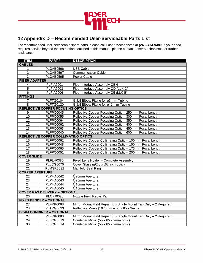
12 Appendix D – Recommended User-Serviceable Parts List
For recommended user-serviceable spare parts, please call Laser Mechanisms at (248) 474-9480. If your head requires service beyond the instructions outlined in this manual, please contact Laser Mechanisms for further assistance.
ITEM PART # DESCRIPTION
CABLES
1 PLCAB0596 USB Cable
2 PLCAB0597 Communication Cable
3 PLCAB0595 Power Cable
FIBER ADAPTER
4 PLFIA0001 Fiber Interface Assembly QBH
5 PLFIA0003 Fiber Interface Assembly QD (LLK-D)
6 PLFIA0006 Fiber Interface Assembly Q5 (LLK-B)
FITTINGS
7 PLFTG0104 G 1/8 Elbow Fitting for ᴓ6 mm Tubing
8 PLFTG0120 G 3/8 Elbow Fitting for ᴓ12 mm Tubing
REFLECTIVE COPPER FOCUSING OPTICS
9 PLFPC0045 Reflective Copper Focusing Optic – 250 mm Focal Length
10 PLFPC0055 Reflective Copper Focusing Optic – 300 mm Focal Length
11 PLFPC0064 Reflective Copper Focusing Optic – 350 mm Focal Length
12 PLFPC0062 Reflective Copper Focusing Optic – 400 mm Focal Length
13 PLFPC0063 Reflective Copper Focusing Optic – 450 mm Focal Length
14 PLFPC0040 Reflective Copper Focusing Optic – 600 mm Focal Length
REFLECTIVE COPPER COLLIMATING OPTICS
15 PLFPC0061 Reflective Copper Collimating Optic – 100 mm Focal Length
16 PLFPC0048 Reflective Copper Collimating Optic – 150 mm Focal Length
17 PLFPC0065 Reflective Copper Collimating Optic – 175 mm Focal Length
18 PLFPC0051 Reflective Copper Collimating Optic – 200 mm Focal Length
COVER SLIDE
19 PLFLH0380 Fixed Lens Holder – Complete Assembly
20 PLLCG0070 Cover Glass (Ǿ2.0 x .62 inch optic)
21 PLMSR0032 Manifold Seal Ring
COPPER APERTURE
22 PLPHA0042 Ǿ28mm Aperture
23 PLPHA0043 Ǿ23mm Aperture
24 PLPHA0044 Ǿ18mm Aperture
25 PLPHA0045 Ǿ13mm Aperture
COVER GAS DELIVERY – OPTIONAL
26 PLCFJ0020 Nozzle Field Repair Kit
FIXED BENDER – OPTIONAL
27 PLFRK0088 Mirror Mount Field Repair Kit (Single Mount Tab Only – 2 Required)
28 PLTRG0093 Reflective Mirror (1070 nm – 55 x 85 x 9mm)
BEAM COMBINER – OPTIONAL
27 PLFRK0088 Mirror Mount Field Repair Kit (Single Mount Tab Only – 2 Required)
29 PLBCG0013 Combiner Mirror (55 x 85 x 9mm optic)
30 PLBCG0014 Combiner Mirror (55 x 85 x 9mm optic)

PLMNL0253 REV. A Effective Date: 02/13/17 32 FiberWELD® HR Operation Manual
Figure 38

PLMNL0253 REV. A Effective Date: 02/13/17 33 FiberWELD® HR Operation Manual
13 Appendix E – Configurations
There are many possible configurations for the FiberWELD® HR. To determine the components necessary for your configuration, see the assembly drawing supplied by Laser Mechanisms. There are (3) basic head configurations. See Figure 39.
Figure 39
The dimensions in this section are all millimeters and are for reference. The configurable component categories are:
Fiber Orientation: See Figure 40.
The fiber interface assembly can be rotated in 90° increments into (4) different orientations to suit the manufacturing environment. The (4) configurations are:
Figure 40

PLMNL0253 REV. A Effective Date: 02/13/17 34 FiberWELD® HR Operation Manual
14 Appendix F – Fiber End Types
Fiber End Type Sample Image
HLC or QBH
QD or LLK-D
Q5 or LLK-B

Laser Mechanisms, Inc.
25325 Regency Drive • Novi, Michigan 48375 USA
Phone: (248) 474-9480 • Fax: (248) 474-9277
In Europe: Phone: +32(0)92 18 70 70 • Fax: +32(0)92 18 70 79
Web: www.lasermech.com • E-Mail: [email protected]