ficon channel extension technology and customer use
TRANSCRIPT

FICON Channel Extension Technology and Customer Use
Mike Blair Cisco Systems
Wednesday, February 6, 2013 Session 13062

Abstract
• This session will discuss FICON channel extension as a part of disaster recovery plan at many companies. When backup datacenters are across a campus from each other, there is nothing to worry about but with today's regulations and industry best practices, most companies have their datacenter tens, hundreds, even thousands of kilometers apart. This session will discuss in detail the technologies needed to assist the base FICON support of the mainframe for acceptable performance and usability.

Agenda
• Optical Solutions • Issues for Extended Distance • How does FCIP help this • Protocol Acceleration • Tape • XRC

Limited by Optics (Power Budget)
SAN Extension Technology Options
Dark Fiber
CWDM
DWDM
SONET/SDH
Data Center Campus Metro Regional National
Increasing Distance
Sync (1,2,4 Gbps)
Sync (1,2 Gbps + Subrate)
Async (WAN,1 Gbps) MDS9000 FCIP
Limited by Optics (Power Budget)
Limited by BB_Credits Opt
ical
IP
Sync (1,2,4,10 Gbps per λ)
Sync (Metro Eth)
Async
Global
Sync (Any Speed)

5
Coarse Wavelength Division Multiplexing (CWDM)
• 8-channel WDM at 20nm spacing (cf DWDM at <1nm spacing) • 1470, 1490, 1510, 1530, 1550, 1570, 1590, 1610nm
• “Colored” CWDM SFPs or XFPs used in FC/FICON directors
• Optical multiplexing done in CWDM OADM (optical add/drop multiplexer) • Passive (unpowered) device—just mirrors and prisms
• Power budget depends on speed • 2G support approx. 100km • 4G support approx. 40km
OADM Mux/Demux

DWDM Schematic
Low Cost MM/SM 850nm/1310nm
OA"
Routers"
SAN"
ATM"
ITU-T grid 15xxnm Transponders "
Wavelength Multiplexed Signals "
Optically Amplified Wavelengths"
DWDMMux"
(Filter)"OA"
OEO"
OEO"
OEO"
OA"
Optical Amplifier
7
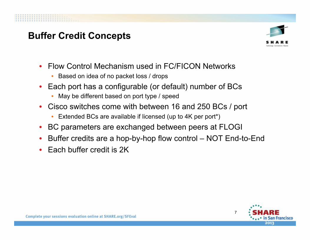
Buffer Credit Concepts
• Flow Control Mechanism used in FC/FICON Networks • Based on idea of no packet loss / drops
• Each port has a configurable (or default) number of BCs • May be different based on port type / speed
• Cisco switches come with between 16 and 250 BCs / port • Extended BCs are available if licensed (up to 4K per port*)
• BC parameters are exchanged between peers at FLOGI • Buffer credits are a hop-by-hop flow control – NOT End-to-End • Each buffer credit is 2K
8
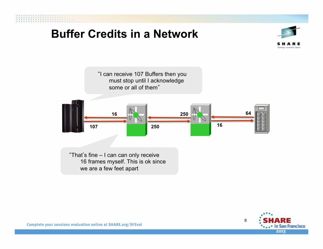
Buffer Credits in a Network
107
16
250
250 64
16
“I can receive 107 Buffers then you must stop until I acknowledge some or all of them”
“That’s fine – I can can only receive 16 frames myself. This is ok since we are a few feet apart

9
1 Gbps FC ~ Need 1 Buffer Credit per 2 Km
Relationship of Speed to Buffer Credits
2 Gbps FC ~ Need 1 Buffer Credit per 1 Km
4 Gbps FC ~ Need 2 Buffer Credits per 1 Km
8 Gbps FC ~ Need 4 Buffer Credits per 1 Km
Theoretically - For 8 Km 1G needs 4, 2G needs 8, 4G needs 16, 8G needs 32

10
• Simple 4K write • Will not fit into 2 buffers because of headers for FC as well as SB3
72
Control
Write 2084 2084
76
Status Accept 68
Average = (76+2084+2084+72+68) / 5 = 877 Bytes
Number of Buffer Credits - Reality

FICON L4 Flow Control / IU Pacing Device
Write 1 Write 1
Mainframe
2 3
16 Write 1
MDS1 MDS2
16

FICON L4 Flow Control / IU Pacing Device
Write 1 Write 1
Mainframe
2 3
16 Write 1
Command Resp 1 Command Resp 8
MDS1 MDS2
16

FICON L4 Flow Control / IU Pacing Device
Write 1 Write 1
Mainframe
2 3
16 Write 1
Command Resp 1
Command Resp 1
Command Resp 8
Command Resp 8 17
Command Resp 16
MDS1 MDS2
Command Resp 1
16

FICON L4 Flow Control / IU Pacing Device
Write 1 Write 1
Mainframe
2 3
16 Write 1
Command Resp 1
Command Resp 1
Command Resp 8
Command Resp 8 17
24
Command Resp 16
Write 17
MDS1 MDS2
Command Resp 1
16
Command Resp 16
24

FICON L4 Flow Control / IU Pacing
Device Idle
Device Write 1
Write 1
Mainframe
2 3
16 Write 1
Command Resp 1
Command Resp 1
Command Resp 8
Command Resp 8 17
24
Command Resp 16
Write 17
Command Resp 24 Status
MDS1 MDS2
Command Resp 1
16
Command Resp 16
24

FICON L4 Flow Control / IU Pacing
Device Idle
Device Write 1
Write 1
Mainframe
2 3
16 Write 1
Command Resp 1
Command Resp 1
Command Resp 8
Command Resp 8 17
24
Command Resp 16
Write 17
Command Resp 24 Status
Status Command Resp 24
Status Accept
New Write Chain
Device Idle
MDS1 MDS2
Command Resp 1
16
Command Resp 16
24
Command Resp 24 Status

FCIP: Fibre Channel over IP
• Point-to-point tunnel between FCIP link end-points • Appears as one logical FC fabric with single FSPF routing domain FICON is just another upper layer protocol that can be transported over IP • FICON over FCIP can provide cost-effective channel extension
17
FC/FICON SAN FC/FICON SAN
IP Network
FCIP Is a Standard from the IETF IP Storage WG for Linking FibreChannel SANs over IP (RFCs 3821 and 3643)
FCIP Tunnel

FCIP Frame Detail
• Max FibreChannel frame is 2148 bytes plus optional extras • FC frames are segmented and reassembled if MTU too small (TCP
payload on second or subsequent packets) • Jumbo frames may increase performance
• IP MTU of 2300 avoids splitting of TCP frames
18
Ethernet Header
IP Header
TCP Header
TCP Opts
FCIP Header FC Frame Ethernet
CRC32 14 20 20 12 28 4
94
EISL Hdr
SOF
4 8
Max 2148 (E_Port) + EISL and Opt Headers FCIP Overhead for Ethernet Frames:
94 Byte Header + 4 Byte CRC = 98 Bytes
EISL and Optional Headers
If TE_Port, then 8 Bytes Added to FC Frame (after SOF) for VSAN Routing
opt Hdr 0-16
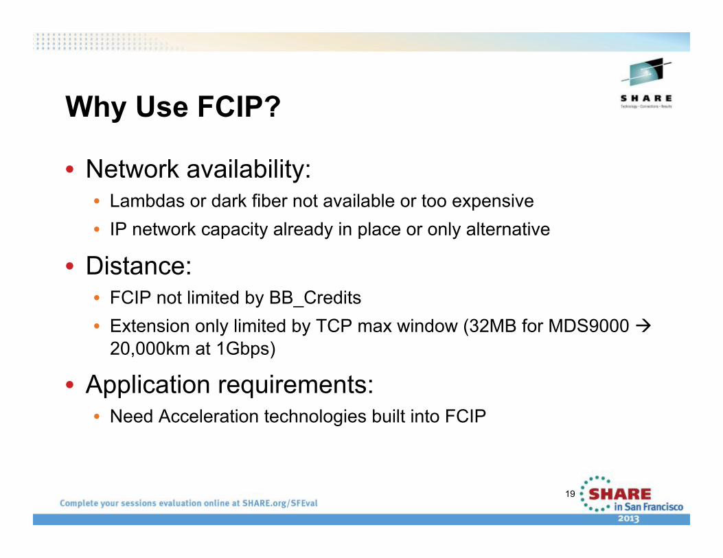
Why Use FCIP?
• Network availability: • Lambdas or dark fiber not available or too expensive • IP network capacity already in place or only alternative
• Distance: • FCIP not limited by BB_Credits • Extension only limited by TCP max window (32MB for MDS9000
20,000km at 1Gbps)
• Application requirements: • Need Acceleration technologies built into FCIP
19

Storage Traffic and TCP
• Storage traffic: • Quite bursty • Latency sensitive (sync apps) • Requires high, instantaneous throughput
• Traditional TCP: • Tries to be network sociable • Tries to avoid congestion (overrunning downstream routers) • Backs off when congestion detected • Slow to ramp up over long links (slow start and
congestion avoidance)

MDS FCIP TCP Behavior
• Reduce probability of drops • Bursts controlled through per flow shaping and congestion window control less likely to overrun routers
• Increased resilience to drops • Uses SACK, fast retransmit and shaping
• Aggressive slow start q • Initial rate controlled by “min-available-bandwidth” • Max rate controlled by “max-bandwidth”
Differences with Normal TCP:
When congestion occurs with other conventional TCP traffic, FCIP is more aggressive during recovery (“bullying” the other traffic)
Aggression is proportional to the min-available-bandwidth configuration

Round Trip Time
Configuring the round-trip-time parameter: • Not necessarily symmetric • Use ping and measure-rtt commands to calculate • Automatically calculated in Cisco MDS
End-to-end latency * 2 = 24 ms RTT.
gigE 45-Mbps gigE
45-Mbps max_bw (dedicated)
12-ms
12-ms

TCP Maximum Window Size
MWS = Maximum bandwidth x RTT Example: 5-ms latency = 10-ms RTT x 155-Mbps (OC-3) = 192-KB • Under dimensioning will throttle throughput • Over dimensioning can cause congestion • Use the bandwidth of the lowest speed link
RTT 10-ms
Bandwidth 155-Mbps
(OC-3)
To keep the pipe full: 155-Mbps x 10-ms = 192-KB
Set the TCP MWS to

TCP Maximum Bandwidth
Configure the TCP max-bandwidth value as follows: • No larger than smallest pipe in the path • If sharing the pipe, configure to be highest amount available to FCIP • In a shared environment, configure QoS in the entire path
max_bw 45-Mbps (dedicated)
max_bw 45-Mbps (shared)
100-Mbps 100-Mbps
45 Mbps
155-Mbps GigE GigE
GigE GigE

TCP Minimum Available Bandwidth
Configure TCP min-available-bandwidth value as follows: • If dedicated path, min-available-bandwidth = max-bandwidth • If shared path, use least amount that is always available to FCIP • Lower if you see frequent retransmissions in a shared transport • Must be at least 1/20 of max-bandwidth
max_bw 45-Mbps (dedicated)
max_bw 45-Mbps (shared)
100-Mbps 100-Mbps
min_bw 45-Mbps (dedicated)
min_bw 20-Mbps (shared) Must be higher than 1/20 of TCP max-bw
155-Mbps GigE GigE
45-Mbps GigE GigE

Results of Packet Shaping
Round Trips
Max_Window Size
Slow Start Threshold
1 2 3 4 5 6 7 8 9 10 11 12 13 14 15
Pac
kets
Sen
t per
Rou
nd T
rip
(Con
gest
ion
Win
dow
)
Traditional TCP Congestion Avoidance
Packet Shaping
Shaper engaged during first RTT = min-available-bw
Slow Start Threshold initialized to 95%
MWS after one RTT
Minimum threshold = min-available-bw
Retransmission
Congestion Avoidance (+2 cwnd per RTT)

FCIP – Multiple FCIP Tunnels
Using GE Sub-Interfaces, Multiple FCIP Tunnels and Port Channeling to Enable High b/w FCIP • Use separate VSANs for data replication (100) and tape acces (200) • Port channel FCIP tunnels for replication traffic for load balancing • Tape access Links are not port channeled
Note – When multiple FCIP tunnels are on the same interface, they use a different TCPIP port numbers
VSAN 100 Replication VSAN 100
VSAN 200
int fcip 11
int fcip 12
int fcip 21
int fcip 22
GigE1/1.100
GigE1/1.200
GigE1/2.100
GigE1/2.200
int fcip 11
int fcip 12
int fcip 21
int fcip 22
GigE1/1
GigE1/2
GigE1/1 GigE1/1.100 VSAN 100
Replication
VSAN 200 Tape Access
GigE1/1.200
GigE1/2 GigE1/2.100
GigE1/2.200
VSAN 100
VSAN 200 Tape Access
VSAN 200

FCIP – Multiple FCIP Tunnels
Now, Configure QOS based on business priorities of data • VSAN 100 – high priority – disk mirroring • VSAN 200 – med priority – Tape backups • VSAN 300 (not shown) – low priority (open systems SAN stuff)
Making the assumption that this is a dedicated SAN WAN infrastructure – but within that, prioritization is needed.
Note: Routers and Switches MUST be QOS aware.
VSAN 100 Replication VSAN 100
VSAN 200
int fcip 11
int fcip 12
int fcip 21
int fcip 22
GigE1/1.100
GigE1/1.200
GigE1/2.100
GigE1/2.200
int fcip 11
int fcip 12
int fcip 21
int fcip 22
GigE1/1
GigE1/2
GigE1/1 GigE1/1.100 VSAN 100
Replication
VSAN 200 Tape Access
GigE1/1.200
GigE1/2 GigE1/2.100
GigE1/2.200
VSAN 100
VSAN 200 Tape Access
VSAN 200

FCIP Data Compression • Cisco uses RFC standard compression algorithms
implemented in both hardware and software • MDS 9000 18/4 MSM and SSN-16
• Third Generation IP Services Modules • Hardware and software-based compression, hardware-based encryption,
and intelligent fabric-based application services
• Three compression algorithms—modes 1–3 plus auto mode
• Compressibility is data stream dependent • All nulls or ones → high compression (>30:1) • Random data (e.g., encrypted) → low compression (~1:1)
• “Typical” rate is around 4:1, but may vary considerably • Application throughput is the most important factor

IPSec Encryption for FCIP
• Data confidentiality—sender can encrypt packets before transmitting them across a network
• Data integrity—receiver can authenticate packets sent by the IPSec sender to ensure that the data has not been altered during transmission
• Data origin authentication—receiver can authenticate the source of the IPSec packets sent; this service is dependent upon the data integrity service
• Anti-replay protection—receiver can detect and reject replayed packets
FCIP Link Encryption Provides:

Primary Site
Remote Tape Backup
Remote Replication
Tape Backup and Remote Replication Secured with IPsec
IP Network
Hardware-Based IPSec Encryption
• Hardware-based GigE wire-rate performance with latency ~ 10 µs per packet
• Standards-based IPSec encryption—implements RFC 2402 to 2410, and 2412 • IKE for protocol/algorithm negotiation and key generation • Encryption: AES (128 or 256 bit key), DES (56 bit), 3DES (168 bit)

Sun VSM to RTD Extension
FICON FICON
VSM at local site writing both a local tape copy as well as a tape copy at the archived site.

FICON Tape Write Acceleration
• Accelerates Writes by means of local acknowledgement • Command Response • Status
• Data is never fully owned by the FTA • Sync command is not emulated – insures data integrity
• Flow control to limit amount of data read to WAN rate • Tape control, label processing, etc are not accelerated

Backup protocol without acceleration
Cisco MDS Cisco MDS
ScratchVol mount, Write VolHdrs etc.
VSM/Tape Library
Write Chain
FCIP Mainframe

Backup protocol without acceleration …
Cisco MDS Cisco MDS
ScratchVol mount, Write VolHdrs etc.
VSM / Tape Library
Write Chain
Status
Write Chain
FCIP
TAPE IDLE
Mainframe

Backup protocol without acceleration …
All data on Media
Cisco MDS Cisco MDS
ScratchVol mount, Write VolHdrs etc.
VSM / Tape Library
Write Chain
Status
Write Chain
Status
Status
SYNC
Rewind Unload
FCIP
TAPE IDLE
Mainframe
TAPE IDLE

Backup protocol with acceleration
Host-side FCIP
Tape-Side FCIP
ScratchVol mount, Write VolHdrs etc.
VSM / Tape Library
Write Chain 1 Write Chain
1 New OXID
Mainframe

Backup protocol with acceleration …
Host-side FCIP
Tape-Side FCIP
ScratchVol mount, Write VolHdrs etc.
VSM / Tape Library
Write Chain 2
Write Chain 1 Write Chain
1 New OXID
Mainframe

Backup protocol with acceleration …
All data on Media
Host-side FCIP
Tape-Side FCIP
ScratchVol mount, Write VolHdrs etc.
VSM / Tape Library
Write Chain 2
Rewind Unload
Write Chain 1 Write Chain
1 New OXID
SYNC
Mainframe

FICON Tape Read Acceleration
• Accelerates Reads by • Learning Read Data Pattern • Entering Acceleration mode • Flowing off the host / Pre-reading data on CU • Stage data at host side – continue reading at the tape side • Start up the host reading the staged data
• If too much data is pre-read, FTA will reposition the tape • Tape control, label processing, etc are not accelerated

FICON Tape Read Acceleration

Sample Performance for FTA Write
FICON FICON
Empirix Distance Simulator
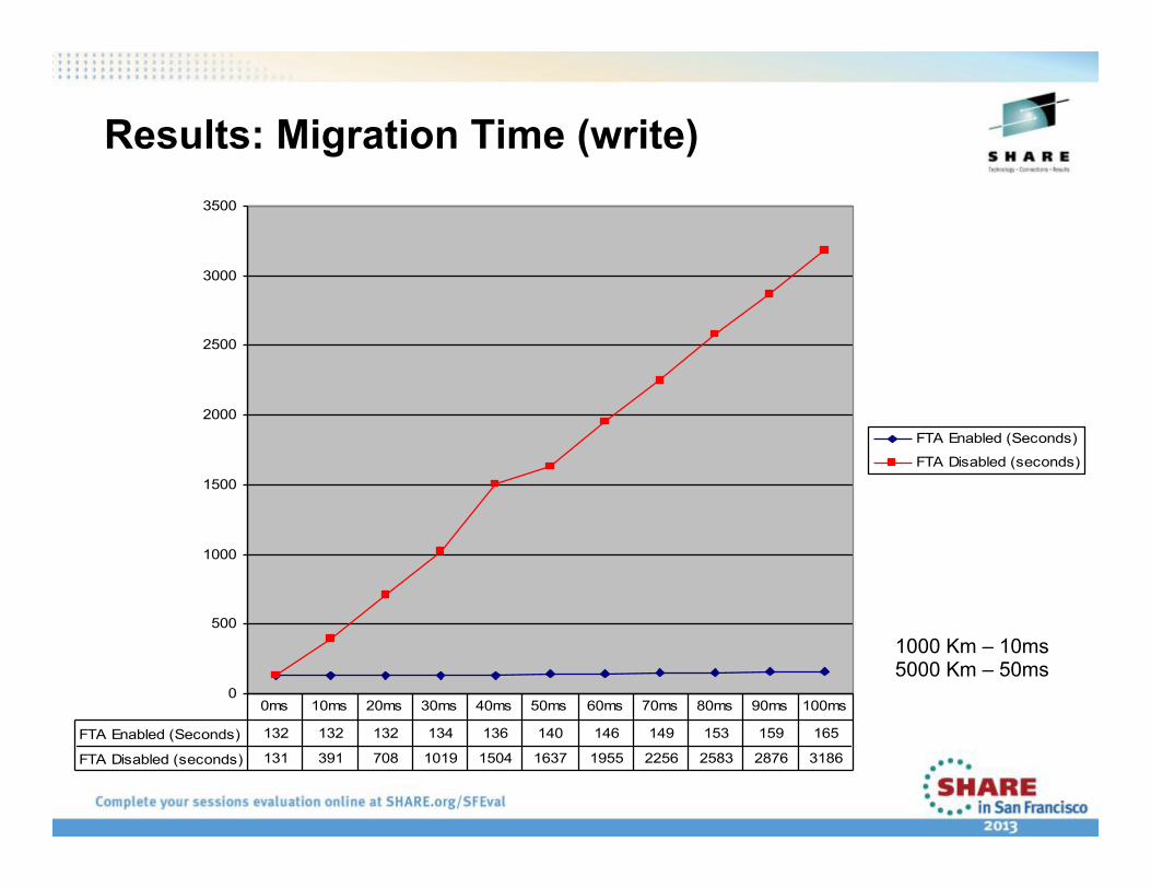
Results: Migration Time (write)
0
500
1000
1500
2000
2500
3000
3500
FTA Enabled (Seconds)
FTA Disabled (seconds)
FTA Enabled (Seconds) 132 132 132 134 136 140 146 149 153 159 165
FTA Disabled (seconds) 131 391 708 1019 1504 1637 1955 2256 2583 2876 3186
0ms 10ms 20ms 30ms 40ms 50ms 60ms 70ms 80ms 90ms 100ms
1000 Km – 10ms 5000 Km – 50ms

Results: Throughput (write)
0.000
2.000
4.000
6.000
8.000
10.000
12.000
14.000
16.000
18.000
0ms 10ms 20ms 30ms 40ms 50ms 60ms 70ms 80ms 90ms 100ms
FTA Enabled (MB/sec)
FTA Disabled (MB/sec)
Thro
ughp
ut –
MB
/s
Site-Site Delay
1000 Km – 10ms 5000 Km – 50ms

FTA Configuration Information
• Only one active FTA-enabled FCIP link is allowed between two domains. Port Channels of FTA-enabled links are not supported. • This is due to the fact that state is kept on a per-port basis.
• Multiple/all ports on a IPS card can run FTA simultaneously • Each of the links must be trunking a different VSAN.
• 8 FICON VSANs are allowed per MDS Chassis – each of these with its own CUP for management.
• The number of write chains buffered is automatically adjusted based on the tape speed and the RTT of the FCIP connection

FTA – More Details
• There is support for both 3590 and 3490 real FICON tape drives. There is support for 3490 Virtual Tapes • IBM and STK have both only implemented 3490 Virtual Tapes in their VTS and VSM platforms respectively. • 3490 versus 3590 selection is dynamic and no configuration is needed for device selection. There can be 3490 and 3590 on the same FCIP link at the same time.
• Multipath is supported from the host to the tape. • These multiple paths must still transverse the same FCIP link but this gives higher host-side redundancy.

VSM - RTD Customer Example - EMEA
47
OC-12
OC-12
600 Miles short path
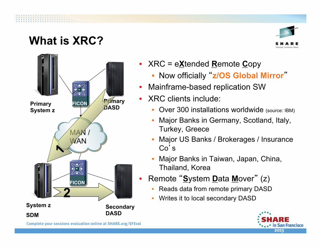
What is XRC?
• XRC = eXtended Remote Copy • Now officially “z/OS Global Mirror”
• Mainframe-based replication SW • XRC clients include:
• Over 300 installations worldwide (source: IBM)
• Major Banks in Germany, Scotland, Italy, Turkey, Greece
• Major US Banks / Brokerages / Insurance Co’s
• Major Banks in Taiwan, Japan, China, Thailand, Korea
• Remote “System Data Mover” (z) • Reads data from remote primary DASD • Writes it to local secondary DASD
FICON
FICON
Primary DASD
Secondary DASD
System z
SDM
Primary System z
MAN / WAN
2

What is good and bad about XRC ?
• Disk Vendor Independent • No lock into vendor unique implementations • Can copy from one vendor disk to another • Can be used for migrations from one vendor to another
• Management and control from the mainframe • No reliance on disk-to-disk replication changes • Performance management from Z

XRC Acceleration – How It Works
50
SECONDARY DASD PRIMARY DASD
• Acceleration of RRS channel programs
- Read Record Sets (ie. Updates)
- In DSO (first command in RRS set) we know how to pre-read for the whole chain of data
- We pre-read the data and send across .. thereby filling the pipe.
- This works around the IU limitations in the FICON architecture.

How Fast is it?
• Some performance testing results: • Vs. no Acceleration: • Almost 5x faster at 1600 km • Almost 9x faster at 3200 km

XRC Acceleration – Other Facts
• Works with Cisco port channels • Allows for less disruption when loss of WAN occurs
• Works with all models of Z system • Backwards compatible with all older Z systems • Fully compatible with the new z10 Extended distance FICON
• Can utilize all compression/encryption on FCIP hardware • Supports all 3 major vendor’s disk arrays • Supports multi-reader, PAVs, and Hyper PAVs • This is a separately licensed feature through IBM

XRC Customer Example – North America
53
All x2
OC-xx