fidic, extension to time for completion and liquidated ... · making the difference fidic range of...
TRANSCRIPT
© Turner & Townsend plc December 11 making the difference
FIDIC, extension to Time for Completion and liquidated damages in the Middle East
April 2014

2
FIDIC, extension to Time for Completion and liquidated damages in the Middle East Timetable
Timetable
Time Topic
5 mins Timetable
8 mins FIDIC Range of Contracts
3 mins Contractual Roles
8 mins The Contractor and Clause 8
4 mins The Contractor and Sub Clause 20.1
2 mins Clause 8 and relevant Sub Clauses
5 mins The Engineer
10 mins Engineer’s calculation and determination
5 mins Employer’s Claims & Delay Damages
10 mins Demonstration and illustration of unliquidated and liquidated damages
5 mins Conclusion
Questions & Answers
Richard Chamberlain

© Turner & Townsend plc December 11 making the difference
FIDIC Range of Contracts

4
GREEN BOOK
4
Short Form of Contract
Recommended for building or engineering works of a relatively small capital value, for relatively simple work, or work of a short duration.
5
RED BOOK
5
Conditions of Contract for Construction for Building and Engineering Works Designed by the Employer
6
PINK BOOK
Construction Contract MDB Harmonised Ed (Version 3: June 2010)
Pink Book project is MDB financed and a development of the Red Book
(Multilateral Development Banks who provide finance for projects in developing countries)
6

7
YELLOW BOOK
7
Conditions of Contract for Plant and Design-Build for Electrical and Mechanical Plant and for Building and Engineering Works designed by the Contractor
8
SILVER BOOK
8
Conditions of Contract for EPC/Turnkey Projects
.

9
GOLD BOOK
9
Design, Build and Operate Projects (2008)

10
WHITE BOOK
10
Client/Consultant Model Services Agreement (4th Ed 2006)

© Turner & Townsend plc December 11 making the difference
Contractual Roles
13
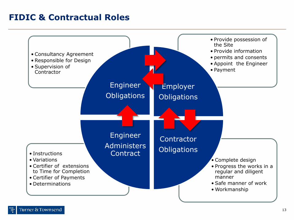
FIDIC & Contractual Roles
• Complete design
• Progress the works in a regular and diligent manner
• Safe manner of work
• Workmanship
• Consultancy Agreement
• Responsible for Design
• Supervision of Contractor
• Provide possession of the Site
• Provide information
• permits and consents
• Appoint the Engineer
• Payment
• Instructions
• Variations
• Certifier of extensions to Time for Completion
• Certifier of Payments
• Determinations
Engineer
Obligations
Employer
Obligations
Contractor
Obligations
Engineer
Administers Contract

making the difference
The Contractor & Clause 8
15
The Contractor
■ The Contractor in FIDIC is :
■ the master of the programme
■ revises the programme when necessary
■ notifies the Engineer of the causes of delay to the programme (Clause 8 and 20)
■ consults with the Engineer to assist in the determination of extension to the Time for Completion
15

16
Clause 8
■ 8.1 Commencement of Work
■ 8.2 Time for Completion
■ 8.3 Programme
■ 8.4 Extension of Time for Completion
■ 8.5 Delays Caused by Authorities
■ 8.6 Rate of Progress
■ 8.7 Delay Damages
■ 8.8 Suspension of Work
■ 8.9 Consequences of Suspension
■ 8.10 Payment for Plant and Materials in Event of Suspension
■ 8.11 Prolonged Suspension
■ 8.12 Resumption of Work
16
17
Sub Clause 8.3 Programme
■ Summary:
■ The Contractor shall submit a programme to the Engineer as required in the Contract.
■ The Employer's Personnel shall be entitled to rely upon the programme when planning their activities.
■ The Contractor shall promptly give notice to the Engineer of specific probable future events or circumstances which may delay the execution of the Works.
■ If the Engineer gives notice to the Contractor that a programme fails the Contractor shall submit a revised programme to the Engineer in accordance with this Sub-Clause.
17
18
Clause 8.4: Extension of Time for Completion
18
■ Summary
■ The Contractor shall be entitled to an extension to Time for Completion, if delayed by any of the following causes:
■ (a) a Variation
■ (b) a cause of delay under a Sub-Clause of these Conditions
■ (c) exceptionally adverse climatic conditions
■ (d) any Unforeseeable delay, impediment or prevention caused by Employer
■ ….”the Contractor shall give notice to the Engineer in accordance with Sub-Clause 20.1 [Contractor's Claims]”
■ ….”the Engineer shall review previous determinations and may increase, with the Employer's written approval, but shall not decrease, the total extension of time”

making the difference
The Contractor and Sub Clause 20.1
20
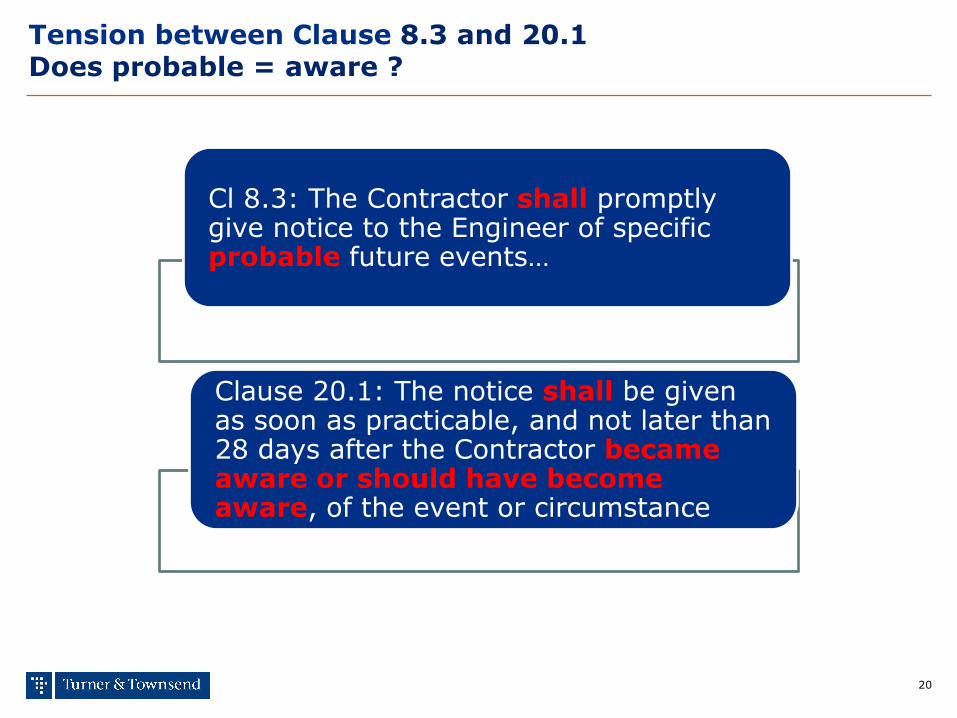
Tension between Clause 8.3 and 20.1 Does probable = aware ?
Cl 8.3: The Contractor shall promptly give notice to the Engineer of specific probable future events…
Clause 20.1: The notice shall be given as soon as practicable, and not later than 28 days after the Contractor became aware or should have become aware, of the event or circumstance

21
Avoiding “probable and aware”
Tension between 8.3 and 20.1
• Notices are in a state of flux • Engineer can time bar • Engineer’s Determination can only be overturned in arbitration
1 2 3 4 5 6 7 8 9 10 11 12 13 14 15 16 17 18 19 20 21 22 23 24 25 26 27 28
1 2 3 4 5 6 7 8 9 10 11 12 13 14 15 16 17 18 19 20 21 22 23 24 25 26 27 28 29 30 31 32 33 34 35 36 37 38 39 40 41 42 1 2 3 4 5 6 7 8 9 10 11 12 13 14 15 16 17 18 19 20 21 22 23 24 25 26 27 28
Cl 8.3 & 20.1"Probable "and "Aware" are
merged
Cl 20.1Fully Detailed Claim
(Interim)
Cl 20.1Fully Detailed Claim
(Interim)
Update or final after end of effects
© Turner & Townsend plc December 11 making the difference
Clause 8 Matrix

23
Clause 8 Matrix of potential causes of delay

© Turner & Townsend plc December 11 making the difference
The Engineer
25
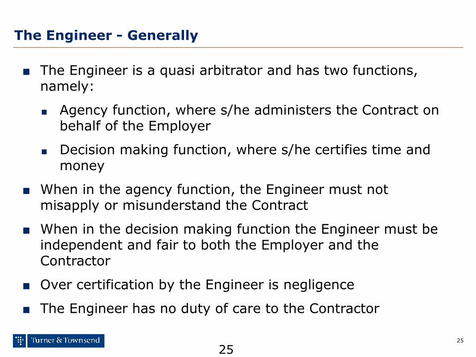
The Engineer - Generally
■ The Engineer is a quasi arbitrator and has two functions, namely:
■ Agency function, where s/he administers the Contract on behalf of the Employer
■ Decision making function, where s/he certifies time and money
■ When in the agency function, the Engineer must not misapply or misunderstand the Contract
■ When in the decision making function the Engineer must be independent and fair to both the Employer and the Contractor
■ Over certification by the Engineer is negligence
■ The Engineer has no duty of care to the Contractor
25

26
The Engineer - Certification
■ The Engineer
■ acts as the Employer’s agent
■ must consult with the Contractor and Employer when differences arise
■ must carry out fair determinations
■ must calculate all certificates in a logical and methodical manner
© Turner & Townsend plc December 11 making the difference
Engineer’s calculation and determination

28
Logical and methodical process
Step 1 -
Investigation
Records
Step 2 -
Summary
Data basing
Analysis
Graphing
Step 3 -
Verification
Method selection
Step 4 -
Analysis
Application of method
Step 5 -
Graphical
Finalisation of Report
Investigation Conclude
Step 6 -
Award
Engineer determines entitlement
Analysis Review

29
Step 1 - Investigation
Step 1
Investigation
Step 2
Summary
Step 3
Verification
Step 4
Analysis
Step 5
Causation
Step 6
Liability
Information Gathering
- Meetings interviews with project team - Orientation meetings with client - Document review (schedule of likely document types included below)
Action Output
No external deliverables
Aims and considerations
Internally: - Chronology - Document mapping - Sequence sketches - General overview notes
Analysis route to be matched to information available and issues identified. Initial aim is to develop robust overview as-planned v as-built.
Investigation
Comment
30
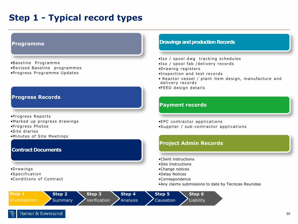
Step 1 - Typical record types
Programme
•Basel ine Programme
•Revised Basel ine programmes
•Progress Programme Updates
Progress Records
•Progress Reports
•Marked up progress drawings
•Progress Photos
•Site diaries
•Minutes of Site Meetings
Contract Documents
•Drawings
•Specif icat ion
•Condit ions of Contract
Drawings and production Records
•Iso / spool dwg tracking schedules
•Iso / spool fab /del ivery records
•Drawing registers
•Inspection and test records
• Reactor vessel / plant i tem design, manufacture and del ivery records
•FEED design detai ls
Payment records
•EPC contractor appl icat ions
•Suppl ier / sub-contractor appl icat ions
Project Admin Records
•Client instructions
•Site Instructions
•Change notices
•Delay Notices
•Correspondence
•Any claims submissions to date by Tecnicas Reunidas
Step 1
Investigation
Step 2
Summary
Step 3
Verification
Step 4
Analysis
Step 5
Causation
Step 6
Liability
31
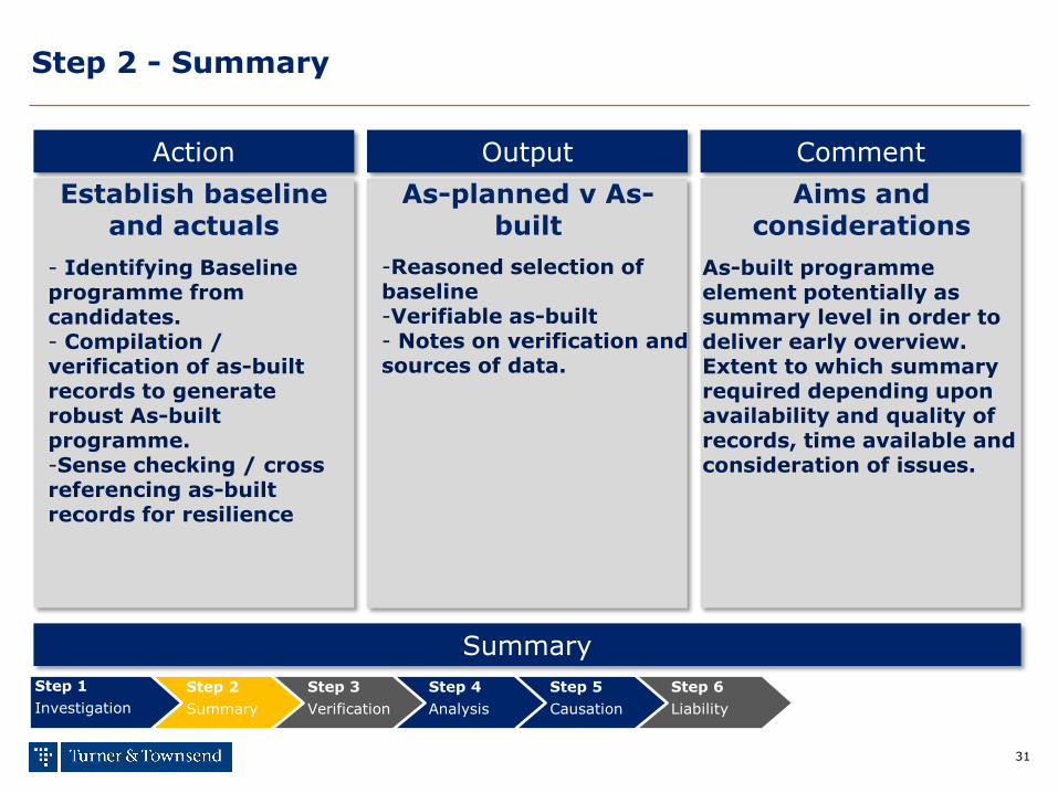
Step 2 - Summary
Step 1
Investigation
Step 2
Summary
Step 3
Verification
Step 4
Analysis
Step 5
Causation
Step 6
Liability
Establish baseline and actuals
- Identifying Baseline programme from candidates. - Compilation / verification of as-built records to generate robust As-built programme. -Sense checking / cross referencing as-built records for resilience
Action Output
As-planned v As-built
Aims and considerations
-Reasoned selection of baseline -Verifiable as-built - Notes on verification and sources of data.
As-built programme element potentially as summary level in order to deliver early overview. Extent to which summary required depending upon availability and quality of records, time available and consideration of issues.
Summary
Comment

32
Step 3 - Verification
Step 1
Investigation
Step 2
Summary
Step 3
Verification
Step 4
Analysis
Step 5
Causation
Step 6
Liability
Interrogation of T&T output
-Review of Step 2 outputs (predominantly As-planned v As-built). -Identification of significant programme variance (delay / sequence change). -Identify key events. - Develop analysis windows.
Action Output
Key Decision point Aims and considerations
-Definition of key events. - Definition of Analysis windows/time slices.
Step presents opportunity to review delays identified and to consider potential causation/ liability positions. Option to substantially modify approach based on findings to date.
Verification
Comment

33
Step 4 - Analysis
Step 1
Investigation
Step 2
Summary
Step 3
Verification
Step 4
Analysis
Step 5
Causation
Step 6
Liability
Detailed investigation
-Review progress by sub dividing the project into a series of windows and examining each window in detail -Analysis will deliver extent and causes of delays in each window. - development of view of actual critical path in each window.
Action Output
No external outputs Aims and considerations
Internally: -Windows analysis and graphics. - Initial report outline. - Notes on causation. - Notes on critical path and critical delays.
Detailed analysis stage. This stage is likely to be time consuming. Initial approach of investigation of most significant areas of delay may be appropriate. NOTE - A selective approach cannot deliver certainty and often increases time and cost to prepare opinion in the long term.
Analysis
Comment
34
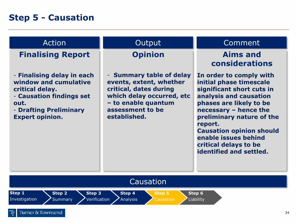
Step 5 - Causation
Step 1
Investigation
Step 2
Summary
Step 3
Verification
Step 4
Analysis
Step 5
Causation
Step 6
Liability
Finalising Report
- Finalising delay in each window and cumulative critical delay. - Causation findings set out. - Drafting Preliminary Expert opinion.
Action Output
Opinion Aims and considerations
- Summary table of delay events, extent, whether critical, dates during which delay occurred, etc – to enable quantum assessment to be established.
In order to comply with initial phase timescale significant short cuts in analysis and causation phases are likely to be necessary – hence the preliminary nature of the report. Causation opinion should enable issues behind critical delays to be identified and settled.
Causation
Comment
35
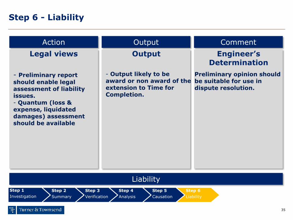
Step 6 - Liability
Step 1
Investigation
Step 2
Summary
Step 3
Verification
Step 4
Analysis
Step 5
Causation
Step 6
Liability
Legal views
- Preliminary report
should enable legal assessment of liability issues. - Quantum (loss & expense, liquidated damages) assessment should be available
Action Output
Output Engineer’s Determination
- Output likely to be award or non award of the extension to Time for Completion.
Preliminary opinion should be suitable for use in dispute resolution.
Liability
Comment
making the difference
FIDIC & Delay Damages
37
Unliquidated or general damages
Employer breaches: • interference and prevention • late supply of information • failure to give possession
Result of Employer breaches is Contractor’s claims for:
•delay • disruption • prolongation • extension to the Time for Completion • additional payment
In summary, the Contractor’s remedy for an Employer’s breach is recovery of general or unliquidated damages. (Note: Unliquidated damages are assessed after the breach)
38
Liquidated damages
Liquidated is a word recognised in the Shorter Oxford Dictionary and from as early as 1574 and is defined as ‘ascertained and fixed’ Questions that arise with respect to liquidated damages:
• Are they an exclusive remedy for a breach? • an agreed price to be paid for a breach or non performance
• Is an agreed price for a breach a penalty? • is the liquidated damage disproportionate to the loss?
• Can the parties agree any price they wish? • freedom of contract –v- penalty
• What is a genuine pre-estimate of loss? • is a genuine precise pre estimate impossible to determine?
•What is the purpose of liquidated damages?
• from Contractor’s perspective it takes away uncertainty and provides an incentive to perform • for Employer, the burden of proving actual loss
39
Middle East (FIDIC delay damages –v- Liquidated damages)
Qatar
• Arabic term for liquidated is fines • principle of ‘freedom of contract is endorsed • principle of ‘good faith’ and bound by terms agreed • pre estimates of liquidated damages are permitted • no distinction between penalties and liquidated damages • FIDIC delay damages replaces liquidated damages • a genuine pre estimate is an important concept • exhaustive remedy depends on drafting • adjustment if no loss is incurred • superseding or contributory fault reduces compensation • liquidated damages provide certainty in contract • liquidated damages are uncertain in law due to exceptions and circumstances A guide to liquidated and ascertained damages for the Qatar construction sector, Warren L, Hall A (2013), Clyde & Co

40
Middle East (FIDIC delay damages –v- Liquidated damages)
United Arab Emirates Construction contracts provide for: • pre determined amount of damages to be paid by Contractor for late completion of a project • liquidated damages are an incentive for the contractor to perform • liquidated damages removes the burden of ascertaining loss The Courts have determined: • liquidated damages is a secondary obligation • delay fines in contracts are a penalty clause and a secondary obligation • termination is fatal to liquidated damages • liquidated damages are an estimate and actual loss is preferred • no loss then liquidated damages should be repudiated • the application of liquidated damages is subjective and prone to the application of exceptions
Liquidated damages under UAE and UK law, a comparison (2014), Ibrahim A, Mullen J, Fenwick Elliot
41
Middle East (FIDIC delay damages –v- Liquidated damages)
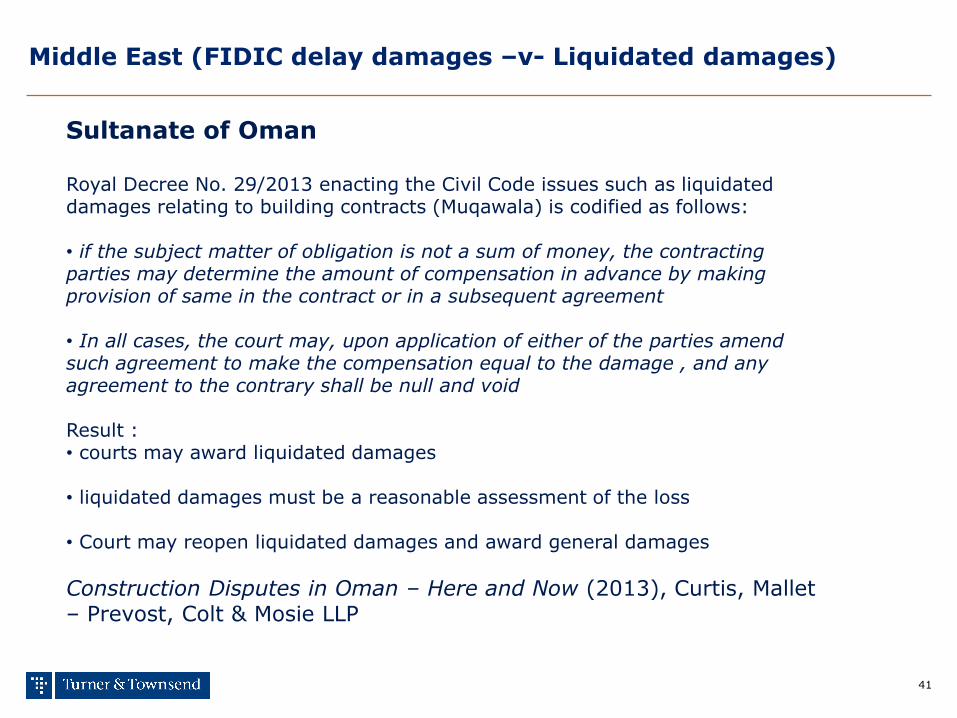
Sultanate of Oman Royal Decree No. 29/2013 enacting the Civil Code issues such as liquidated damages relating to building contracts (Muqawala) is codified as follows: • if the subject matter of obligation is not a sum of money, the contracting parties may determine the amount of compensation in advance by making provision of same in the contract or in a subsequent agreement • In all cases, the court may, upon application of either of the parties amend such agreement to make the compensation equal to the damage , and any agreement to the contrary shall be null and void Result : • courts may award liquidated damages • liquidated damages must be a reasonable assessment of the loss • Court may reopen liquidated damages and award general damages
Construction Disputes in Oman – Here and Now (2013), Curtis, Mallet – Prevost, Colt & Mosie LLP
42
Summary (FIDIC delay damages –v- Liquidated damages)
Principles surrounding liquidated damages : • freedom of contract is acceptable practice • parties free to agree liquidated damages • liquidated damages must be reasonable estimate • liquidated damages can be reopened by the courts • liquidated damages may fall away and be substituted by general damages Conclusion: In respect of the application of liquidated damages in the Middle East there is no such thing as certainty

making the difference
Presenting extensions to Time for
Completion

making the difference
Visualising the Critical Path

45
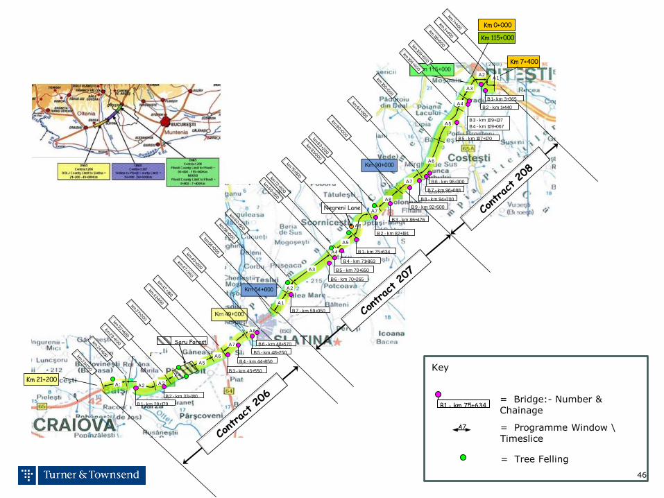
DN65 Contract 206
DOLJ County Limit to Slatina
21+200 to 49+000 Km
DN65 Contract 207
Slatina to Pitesti County Limit 54+000 to
90+000 Km
DN65 Contract 208
Pitesti County Limit to Pitesti = 90+000 to
115+000Km NR65B
Pitesti County Limit to Pitesti
46
Km 21+200
Km 115+000
Km 0+000
Km 7+400
Contract 206
Contract 207
Contract 208
A1
A2
A3
A4
A5
A6
A7
A8
A7
A6
A5
A4
A3
A2A1
A1 A2 A3
A4
A5
A6
A7
A8
Saru Forest
Negreni Lane
B1 - km 28+179
B2 - km 33+180
B3 - km 43+550
B4 - km 44+850
B5 - km 48+250
B6 - km 48+570
B7 - km 59+050
B6 - km 70+265
B5 - km 70+650
B4 - km 71+863
B1 - km 75+634
B2 - km 82+191
B3 - km 86+476
B2 - km 1+440
B1 - km 3+365
B3 - km 109+137
B4 - km 109+067
B5 - km 107+170
B6 - km 96+300
B7 - km 96+088
B9 - km 92+500
B8 - km 94+700
km 21+200
km 24+650
km 29+690
km 41+650
km 42+180
km 47+360
km 49+000
km 7+400
km 3+400
km 115+000km
109+000
km 106+400
km 100+500
km 94+500
km 54+000
km 58+000
km 60+500
km 69+500
km 72+600
km 75+500
km 81+000
km 83+200
km 90+000
km 32+600
km 37+200
Key
= Bridge:- Number & Chainage
B1 - km 75+634
= Programme Window \ Timeslice
A7
= Tree Felling
47
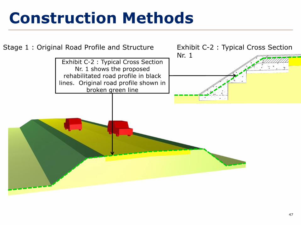
Construction Methods
Stage 1 : Original Road Profile and Structure Exhibit C-2 : Typical Cross Section Nr. 1
Exhibit C-2 : Typical Cross Section Nr. 1 shows the proposed
rehabilitated road profile in black lines. Original road profile shown in
broken green line
48
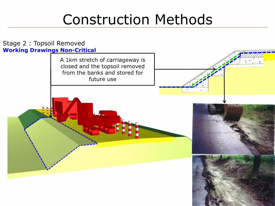
Stage 2 : Topsoil Removed Working Drawings Non-Critical
A 1km stretch of carriageway is closed and the topsoil removed from the banks and stored for
future use
Construction Methods
49
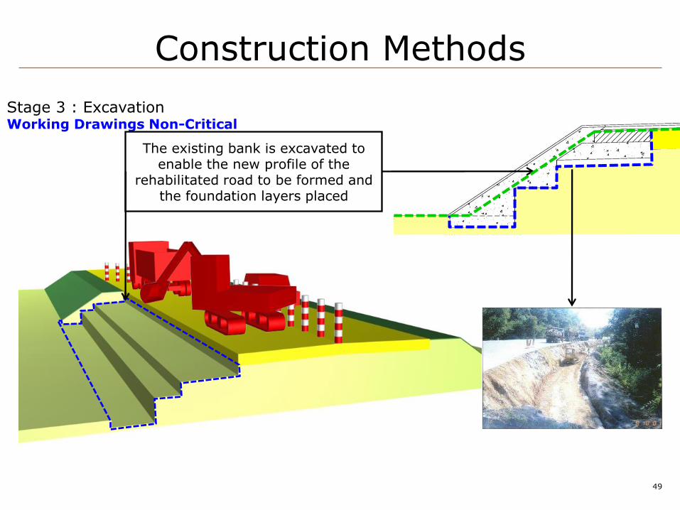
Stage 3 : Excavation Working Drawings Non-Critical
The existing bank is excavated to enable the new profile of the
rehabilitated road to be formed and the foundation layers placed
Construction Methods

50
Stage 4 : Fill to Form Bank Profile Working Drawings Non-Critical
A portion of the excavated area is filled with earth to form the new
road bank profile and enable work to begin on the foundation layers of
the road
Construction Methods
51
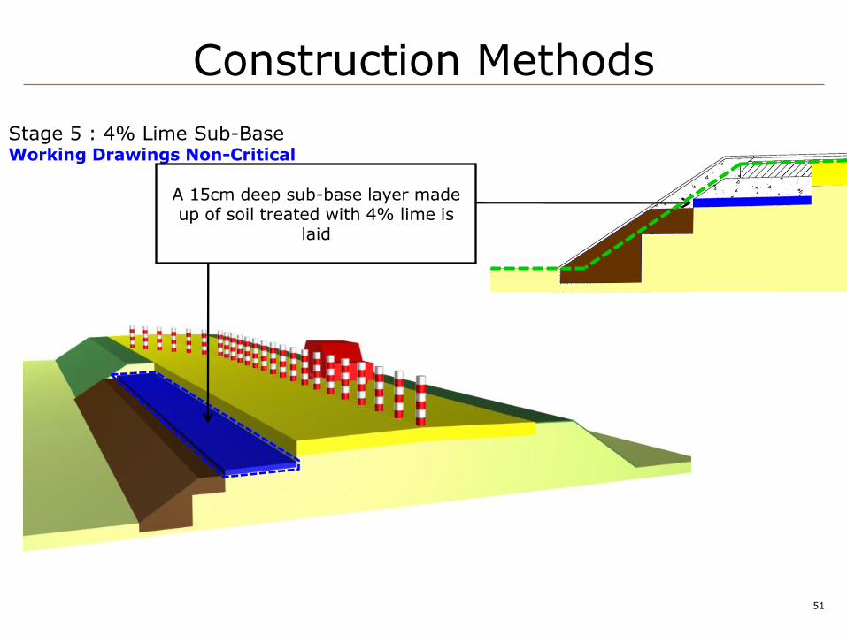
Stage 5 : 4% Lime Sub-Base Working Drawings Non-Critical
A 15cm deep sub-base layer made up of soil treated with 4% lime is
laid
Construction Methods
52
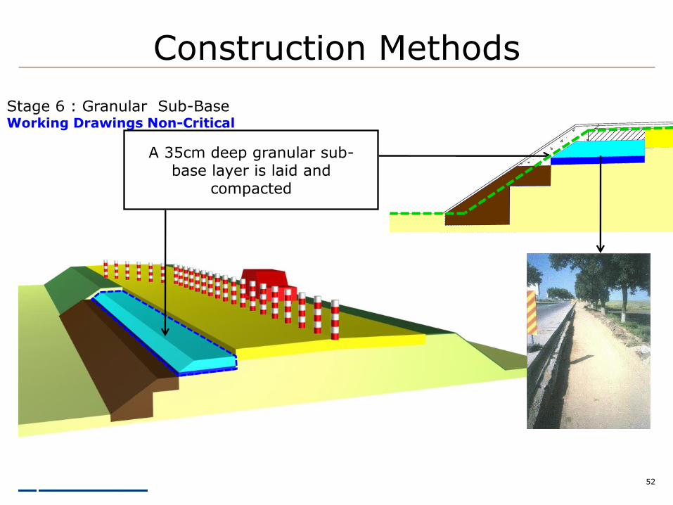
Stage 6 : Granular Sub-Base Working Drawings Non-Critical
A 35cm deep granular sub-base layer is laid and
compacted
Construction Methods
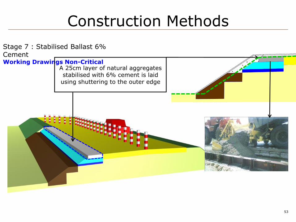
53
Stage 7 : Stabilised Ballast 6% Cement Working Drawings Non-Critical
A 25cm layer of natural aggregates stabilised with 6% cement is laid using shuttering to the outer edge
Construction Methods

54
Stage 8 : Regulating/Base Course Working Drawings Critical
A 4cm base course is laid across the carriageway together with a
regulating course where necessary to achieve the proposed road profile
Construction Methods

55
Stage 9 : Binder Course Working Drawings Critical
A 4cm binder course is laid on top of the base course
Construction Methods
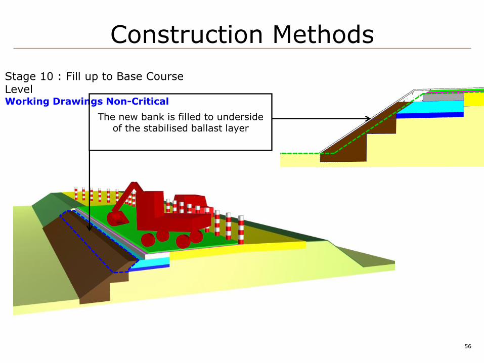
56
Stage 10 : Fill up to Base Course Level Working Drawings Non-Critical
The new bank is filled to underside of the stabilised ballast layer
Construction Methods
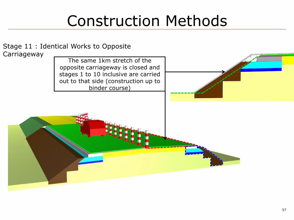
57
Stage 11 : Identical Works to Opposite Carriageway
The same 1km stretch of the opposite carriageway is closed and stages 1 to 10 inclusive are carried out to that side (construction up to
binder course)
Construction Methods
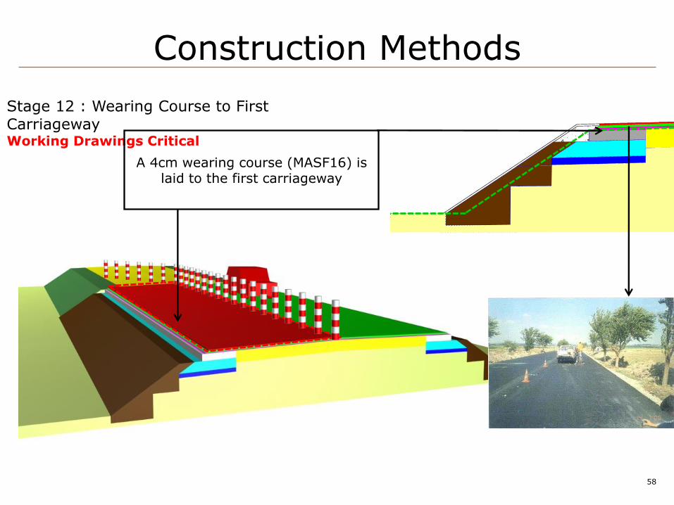
58
Stage 12 : Wearing Course to First Carriageway Working Drawings Critical
A 4cm wearing course (MASF16) is laid to the first carriageway
Construction Methods
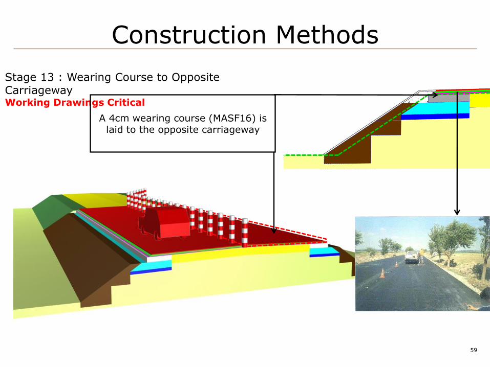
59
Stage 13 : Wearing Course to Opposite Carriageway Working Drawings Critical
A 4cm wearing course (MASF16) is laid to the opposite carriageway
Construction Methods
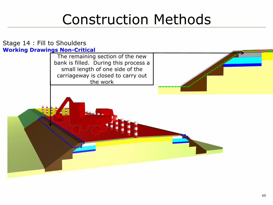
60
Stage 14 : Fill to Shoulders Working Drawings Non-Critical
The remaining section of the new bank is filled. During this process a
small length of one side of the carriageway is closed to carry out
the work
Construction Methods

61
Stage 15 : Topsoil to Banks Working Drawings Non-Critical
Exhibit C-2 : Typical Cross Section Nr. 1 Constructed
The new banks are covered with topsoil using the material removed
in stage 2
Completed Road
Construction Methods
making the difference
Photographs to illustrate the critical path

63
South Central Depot Improvement Contract Littlehampton Depot
Delay Event 1: Bellmouth:
(Entrance to the site and car park and work which has encountered a critical path delay of 34 days)
Volume 1:
7.0 EXTENSION OF TIMEPARTICULARS
DELAY EVENT 1
64
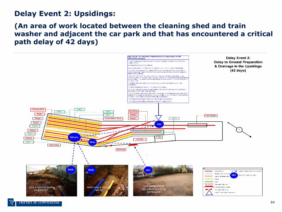
South Central Depot Improvement Contract Littlehampton Depot
Delay Event 2: Upsidings:
(An area of work located between the cleaning shed and train washer and adjacent the car park and that has encountered a critical path delay of 42 days)
Volume 1:
7.0 EXTENSION OF TIMEPARTICULARS
DELAY EVENT 2

65
South Central Depot Improvement Contract Littlehampton Depot
Delay Event 3: Path 6
(An elevated reinforced concrete pathway and canopy located between siding 3 and 4 in the “Backsidings” and that has encountered a critical path delay of 20 days)
Volume 1:
7.0 EXTENSION OF TIMEPARTICULARS
DELAY EVENT 3
66
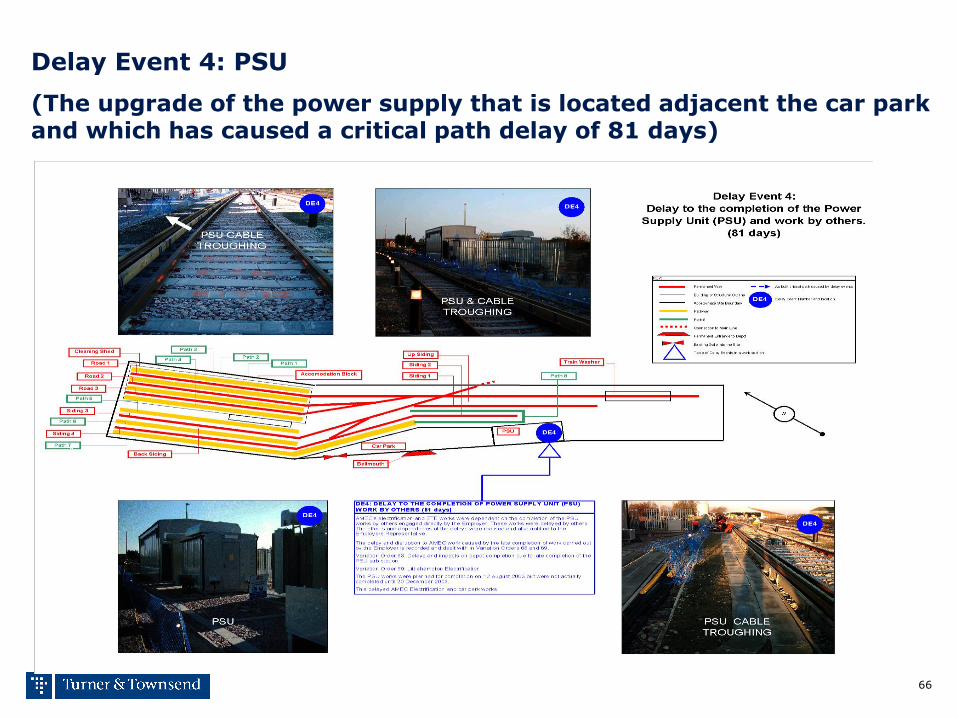
South Central Depot Improvement Contract Littlehampton Depot
Delay Event 4: PSU
(The upgrade of the power supply that is located adjacent the car park and which has caused a critical path delay of 81 days)
Volume 1:
7.0 EXTENSION OF TIMEPARTICULARS
DELAY EVENT 4

67
South Central Depot Improvement Contract Littlehampton Depot
Delay Event 5: ETE
(The late installation of electrical traction engineering, which has resulted in a critical path delay of 17 days)
Volume 1:
7.0 EXTENSION OF TIMEPARTICULARS
DELAY EVENT 5
68
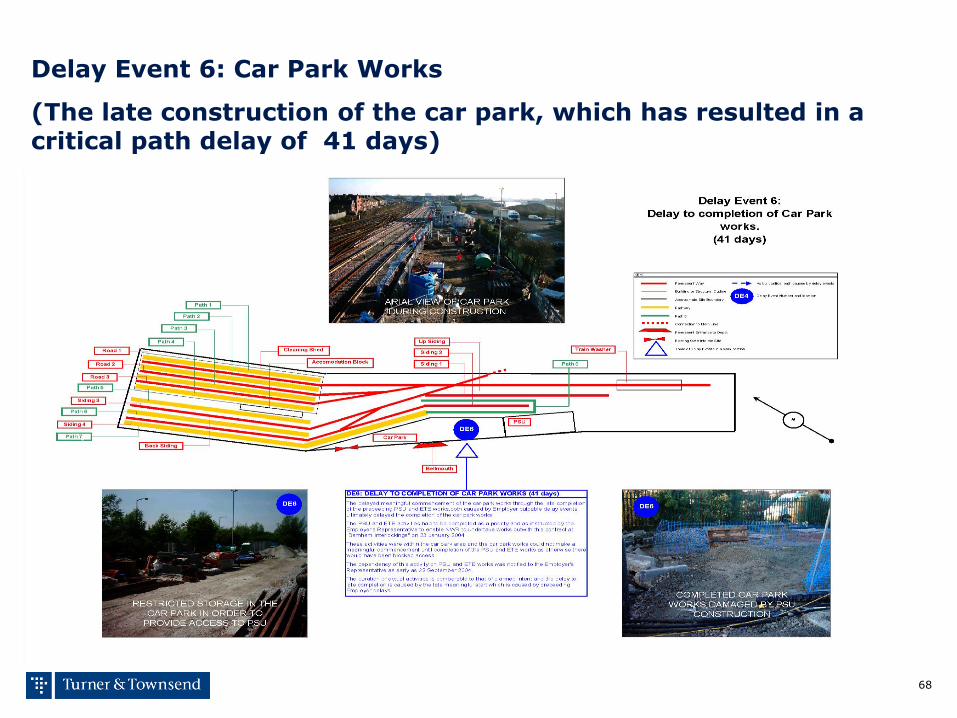
South Central Depot Improvement Contract Littlehampton Depot
Delay Event 6: Car Park Works
(The late construction of the car park, which has resulted in a critical path delay of 41 days)
Volume 1:
7.0 EXTENSION OF TIMEPARTICULARS
DELAY EVENT 6
making the difference
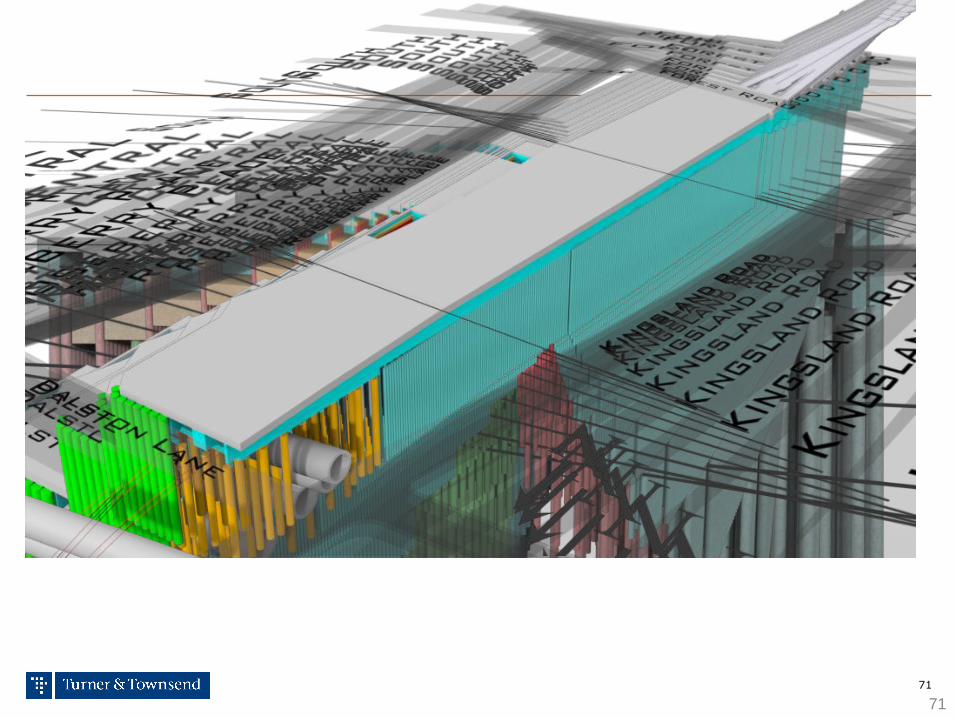
Modelling the critical path
70
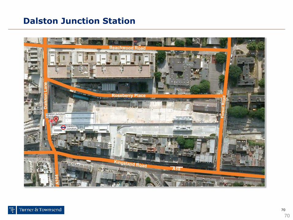
Dalston Junction Station
70
71
71

72
Construction Sequence
72
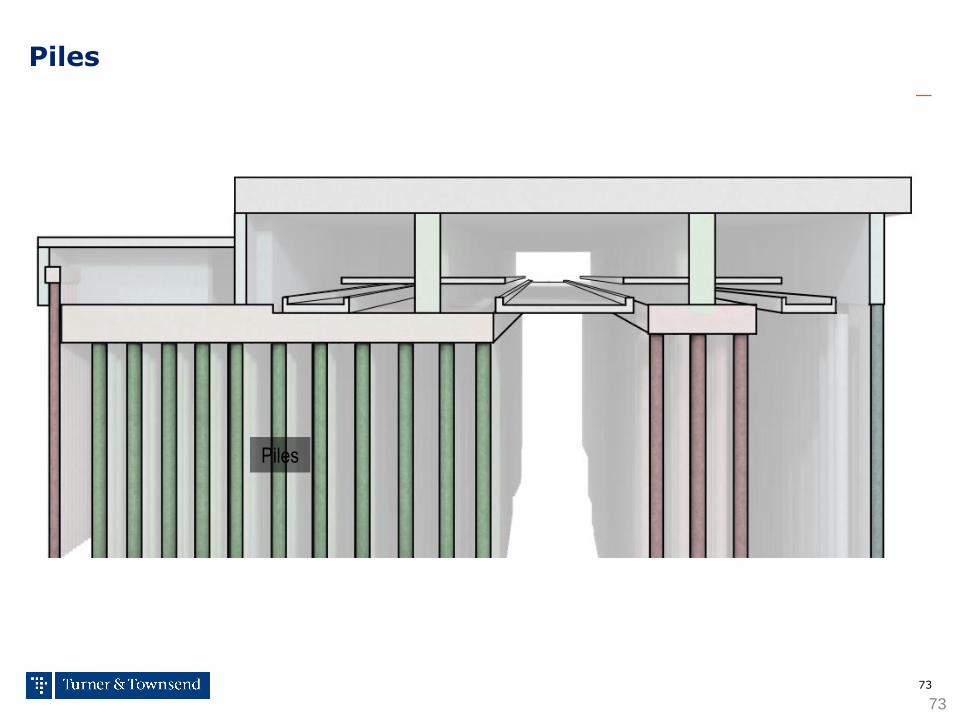
73
Piles
73
Piles

74
Pile Caps
74
Pile Caps
Piles

75
Walls & Columns
75
Pile Caps
Walls Columns
Piles
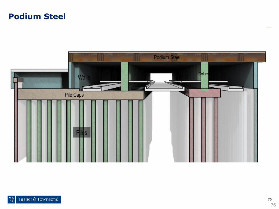
76
Podium Steel
76
Pile Caps
Walls Columns
Podium Steel
Piles
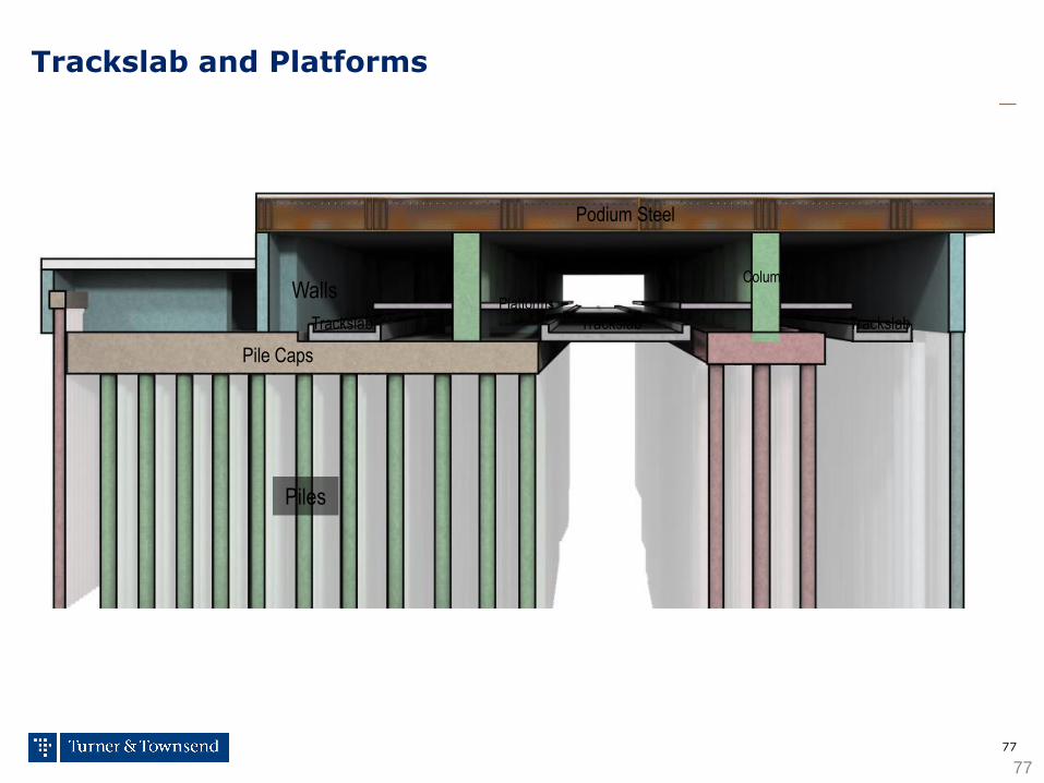
77
Pile Caps
Walls Columns
Podium Steel
Piles
Trackslab
Trackslab and Platforms
77
Trackslab Trackslab Platforms
78
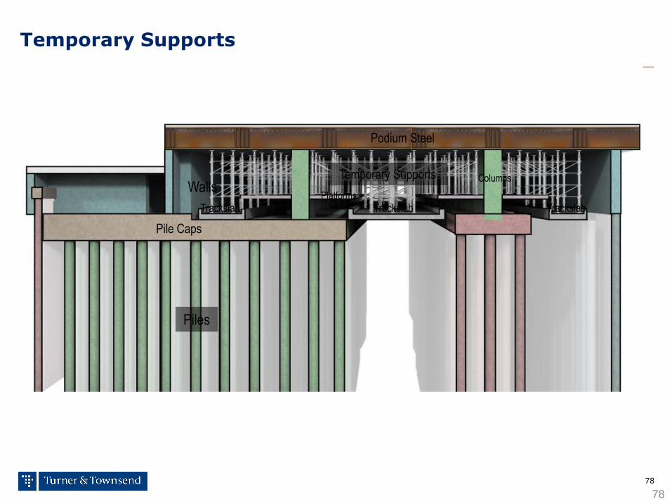
Temporary Supports
78
Pile Caps
Walls Columns
Podium Steel
Piles
Temporary Supports
Trackslab Trackslab Trackslab Platforms
79
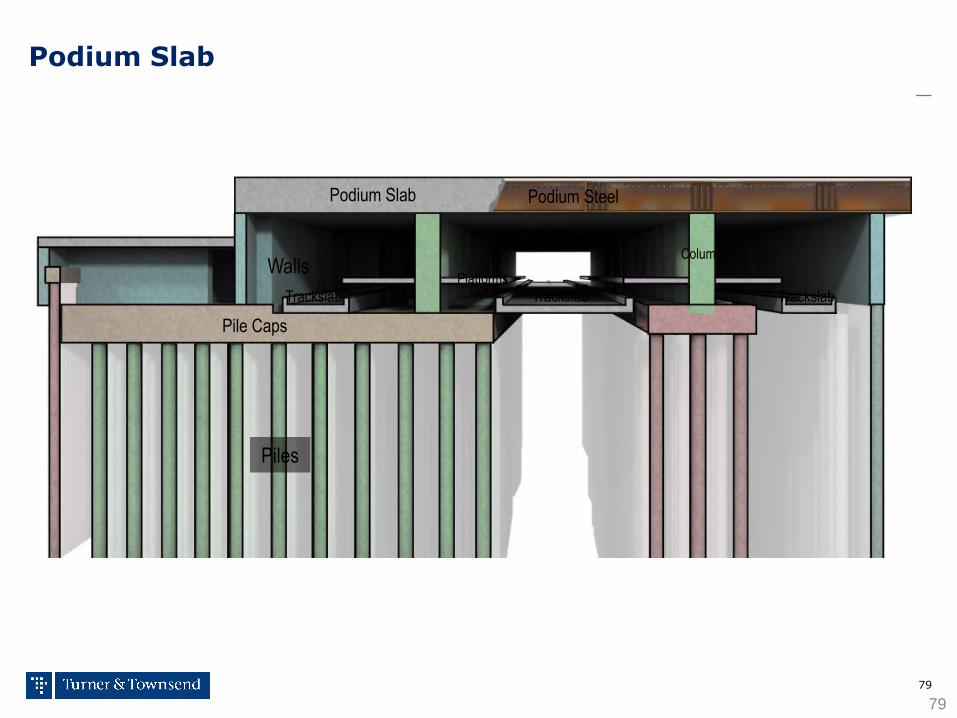
Podium Slab
79
Pile Caps
Walls Columns
Podium Steel
Piles
Podium Slab
Trackslab Trackslab Trackslab Platforms
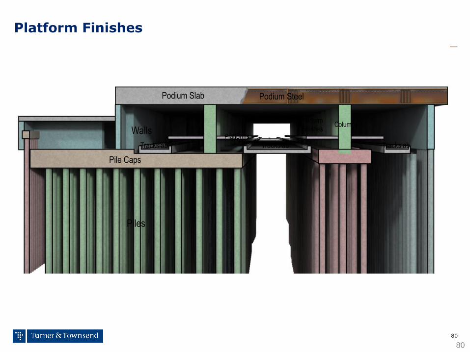
80
Platform Finishes
Pile Caps
Walls Columns
Podium Steel
Piles
Podium Slab
Trackslab Platforms
80
Platform
Finishes
Trackslab Trackslab
making the difference
Flow charting the critical path

82
Flowcharts to assess the impact of variations
Off Site design of software / graphics & development of DOP’s
Revised Minimum Air Volumes
Perforated Plates
Modify Volumes to perimeter zones
Remove Perforated Plate and blank 1 No Bell Mouth
Disable CV Box
Acoustically line 4No Bell Mouths

83
Analysis of commissioning plans
Off Site design of software / graphics & development DOP’s
Note: Off Site Operations should be complete.
• Engineer located at the Head End. • Engineer located at the Controller. • Engineers communicate via radio. • Certain conditions require simulation by the Engineer at the Controller i.e. Boilers and Chillers need not be available. • All points would be checked in this way. • The Specification set out that Systems 33 & 35 should be commissioned separately. • In our opinion, 1 - 2 days would have been allowed to commission System 33. • After all points are checked and both Engineers satisfied, the System is ready for witnessing.
84
SPECIFIED WITNESSING PROCEDURE
Off Site design of software / graphics & development DOP’s
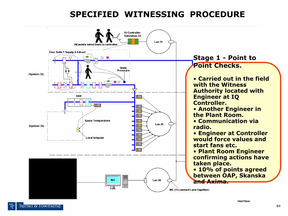
Stage 1 - Point to Point Checks. • Carried out in the field with the Witness Authority located with Engineer at IQ Controller. • Another Engineer in the Plant Room. • Communication via radio. • Engineer at Controller would force values and start fans etc. • Plant Room Engineer confirming actions have taken place. • 10% of points agreed between OAP, Skanska and Axima.
85
SPECIFIED WITNESSING PROCEDURE
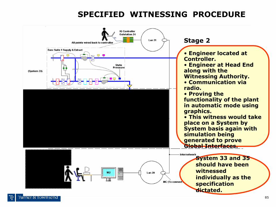
System 33 and 35 should have been witnessed individually as the specification dictated.
Off Site design of software / graphics & development DOP’s
Stage 2 • Engineer located at Controller. • Engineer at Head End along with the Witnessing Authority. • Communication via radio. • Proving the functionality of the plant in automatic mode using graphics. • This witness would take place on a System by System basis again with simulation being generated to prove Global Interfaces.
86
SPECIFIED WITNESSING PROCEDURE
Site design of software / graphics & development DOP’s
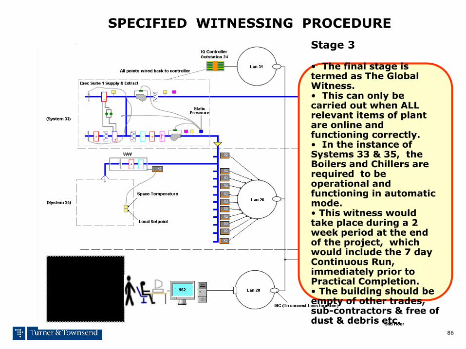
Stage 3 • The final stage is termed as The Global Witness. • This can only be carried out when ALL relevant items of plant are online and functioning correctly. • In the instance of Systems 33 & 35, the Boilers and Chillers are required to be operational and functioning in automatic mode. • This witness would take place during a 2 week period at the end of the project, which would include the 7 day Continuous Run, immediately prior to Practical Completion. • The building should be empty of other trades, sub-contractors & free of dust & debris etc.
making the difference
Bar charts & network analysis
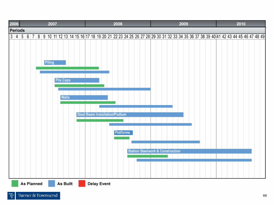
88
Factual Analysis Dealing with Scenario 3 – Impact on Level 3
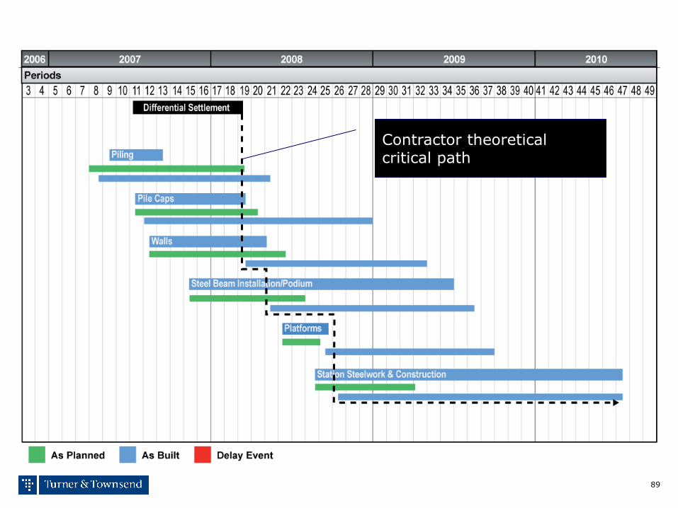
89
Factual Analysis Dealing with Scenario 3 – Impact on Level 3
Contractor theoretical critical path
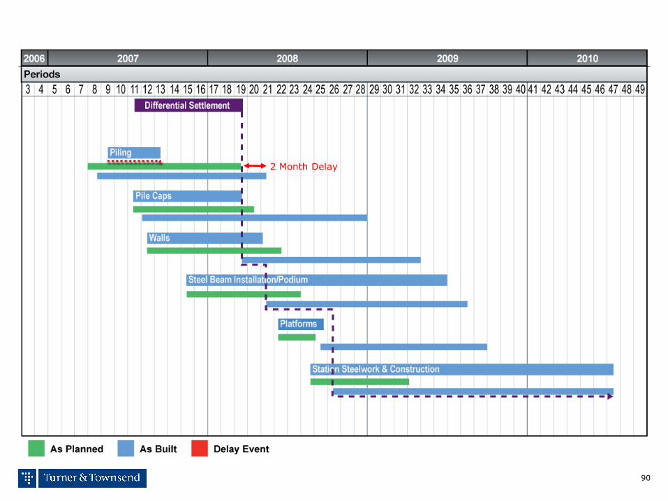
90
2 Month Delay
Factual Analysis Dealing with Scenario 3 – Impact on Level 3

91
7.5 Month Delay
Factual Analysis Dealing with Scenario 3 – Impact on Level 3
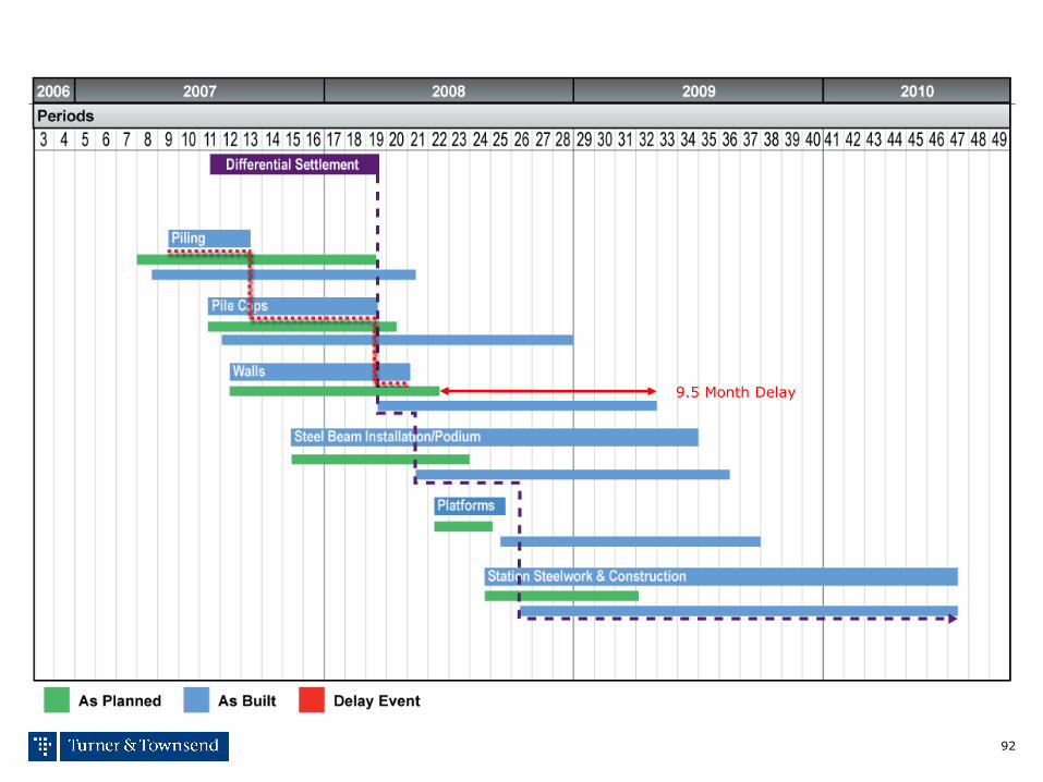
92
9.5 Month Delay
Factual Analysis Dealing with Scenario 3 – Impact on Level 3

93
12 Month Delay
Factual Analysis Dealing with Scenario 3 – Impact on Level 3

94
12 Month Delay
Factual Analysis Dealing with Scenario 3 – Impact on Level 3

95
15 Month Delay
Factual Analysis Dealing with Scenario 3 – Impact on Level 3
Engineer critical path after factual analysis
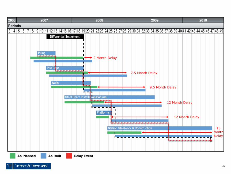
96
15 Month Delay
12 Month Delay
12 Month Delay
9.5 Month Delay
7.5 Month Delay
2 Month Delay
Factual Analysis Dealing with Scenario 3 – Impact on Level 3

making the difference
Charts in general

98
98
Anticipated output = green line
Actual output = Blue Line
Delay Effect = Red Bars
Factual Analysis Dealing with Scenario 2 – Late Detail Design

99
■ The example of the Level 3 programme shows the effect of
design delay in blue background facilities that make up the
project
■ The construction in each facility is being driven out and delayed
by red delay bars that represent late detail design
■ Each red delay bar in each facility has a different effect and
length of delay, this is called causative potency
■ The longest red bar in a facility = the primary critical path and
the others that follow behind are the secondary critical paths
99
PROCUREMENT DELAY EVENT 1: ROOF FANS
PROCUREMENT DELAY EVENT 2: MOLY SCREW DRYER
PROCUREMENT DELAY EVENT 3: AGITATORS
PROCUREMENT DELAY EVENT 4: ROCK BREAKER
PROCUREMENT DELAY EVENT 5: HIGH ANGLE CONVEYORS
PROCUREMENT DELAY EVENT 6: IN PLANT CONVEYORS
PROCUREMENT DELAY EVENT 7: BELT FEEDER
PROCUREMENT DELAY EVENT 8: MOLY BAG FILLING SYSTEM
PROCUREMENT DELAY EVENT 9: BRIDGE CRANE
EPC Planned
Provisional Acceptance
Target Date 31 December 2010
Factual Analysis Dealing with Scenario 2 Level 3 Critical Path Analysis
Primary Critical Path
100
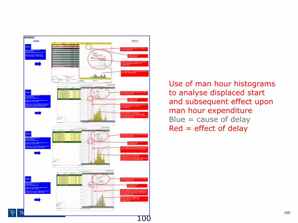
100
Use of man hour histograms to analyse displaced start and subsequent effect upon man hour expenditure Blue = cause of delay Red = effect of delay
Factual Analysis Dealing with Scenario 3 – Resource Analysis

making the difference
Thank You Questions & Answers