field devices – pressure - dp-flow.com.au
TRANSCRIPT
FIELD DEVICES – PRESSUREProduct Specifications
PSS 2A-1C15 C
Model IMV31 I/A Series® Multivariable Transmitters Density-Compensated Level Transmitter with HART® Communication Protocol
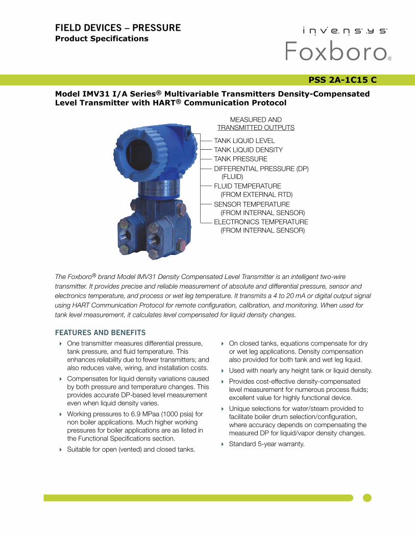
The Foxboro® brand Model IMV31 Density Compensated Level Transmitter is an intelligent two-wire transmitter. It provides precise and reliable measurement of absolute and differential pressure, sensor and electronics temperature, and process or wet leg temperature. It transmits a 4 to 20 mA or digital output signal using HART Communication Protocol for remote configuration, calibration, and monitoring. When used for tank level measurement, it calculates level compensated for liquid density changes.
FEATURES AND BENEFITS
One transmitter measures differential pressure, tank pressure, and fluid temperature. This enhances reliability due to fewer transmitters; and also reduces valve, wiring, and installation costs.
Compensates for liquid density variations caused by both pressure and temperature changes. This provides accurate DP-based level measurement even when liquid density varies.
Working pressures to 6.9 MPaa (1000 psia) for non boiler applications. Much higher working pressures for boiler applications are as listed in the Functional Specifications section.
Suitable for open (vented) and closed tanks.
On closed tanks, equations compensate for dry or wet leg applications. Density compensation also provided for both tank and wet leg liquid.
Used with nearly any height tank or liquid density.
Provides cost-effective density-compensated level measurement for numerous process fluids; excellent value for highly functional device.
Unique selections for water/steam provided to facilitate boiler drum selection/configuration, where accuracy depends on compensating the measured DP for liquid/vapor density changes.
Standard 5-year warranty.
TANK LIQUID LEVEL
DIFFERENTIAL PRESSURE (DP)
FLUID TEMPERATURE
SENSOR TEMPERATURE
ELECTRONICS TEMPERATURE
TANK LIQUID DENSITYTANK PRESSURE
(FROM EXTERNAL RTD)
(FROM INTERNAL SENSOR)
(FROM INTERNAL SENSOR)
(FLUID)
MEASURED ANDTRANSMITTED OUTPUTS

PSS 2A-1C15 CPage 2
Complete configuration capability with Model PCMV configurator, which has a database with extensive fluid properties. Limited configuration with HART Communicator or optional LCD indicator with pushbuttons.
Reduced process penetrations save money and reduce chances of fugitive emissions.
Level values from transmitter eliminate need for other resources for level calculations.
CE marked; complies with EMC, ATEX, and PED European Directives; and NAMUR NE 21 Interference Immunity requirement. Versions available to meet agency flameproof and zone requirements.
Dual Seal certified by CSA to meet ANSI/ISA 12.27.01-2003 requirements.
I/A Series PRESSURE TRANSMITTER FAMILY
The IMV31 is part of a complete family of Foxboro gauge, absolute, d/p Cell®, multirange, multivariable, and premium performance transmitters, as well as transmitters with remote or direct mount pressure seals. They all use field-proven silicon strain gauge sensors and common topworks.
EXCEPTIONALLY HIGH PERFORMANCE
Level accuracy to ±0.30% of maximum level
Tank pressure and DP accuracy to ±0.05% of Span
Long term stability with drift less than ±0.05% URL per year over a 5-year period
Minimized static pressure effect on DP by using pressure to compensate the DP measurement
Excellent ambient temperature effect compensation due to characterization and microprocessor-based compensation
Total Probable Error (TPE) significantly better than typical competitive transmitters
MULTIPLE MEASUREMENTS AND CALCULATIONS
Tank Pressure Differential Pressure (DP) Fluid Temperature from external RTD Tank Liquid Level Tank Liquid Density Sensor Temperature Electronics Temperature
DIGITAL HART AND 4 TO 20 mA DC
4 to 20 mA with HART communications allows direct analog connection to common receivers while still providing full digital communications using a HART Communicator, PC-based configurator, or optional LCD indicator with on-board pushbuttons.
For complete configuration capability, Foxboro Model PCMV PC-based configurator is required. A HART Communicator, PC-based configurator, or optional LCD indicator with pushbuttons can be used for routine transmitter functions such as rezeroing or changing damping settings. See Figure 13 for more information on the LCD digital indicator (Option -L).
OPTIONAL CUSTOM FACTORY CONFIGURATION (OPTION -C2)
Changes can be made to the IMV31 using a HART Communicator, PC-based configurator, or optional local display. These configuration methods cannot configure the IMV31 for a specific application, but can only modify some parameter values after the initial configuration. Therefore, Invensys recommends that IMV31 transmitters be factory configured at time of shipment if the application information is known. To supply the necessary information to the factory, the Factory Configuration Option -C2 Configuration Wizard must be run and the results must be available to BuyAutomation. If Option -C2 is not selected in the Model Code, the user must then have Model PCMV configuration software to fully configure the IMV31 transmitter for a liquid level application. The Device Descriptions and Device Type Manager files available from Invensys can modify some configuration parameters, but only the Model PCMV will calculate the necessary coefficients related to the process liquid and pass them to the transmitter.
PSS 2A-1C15 CPage 3
TANK LEVEL MEASUREMENT AND THE IMV31
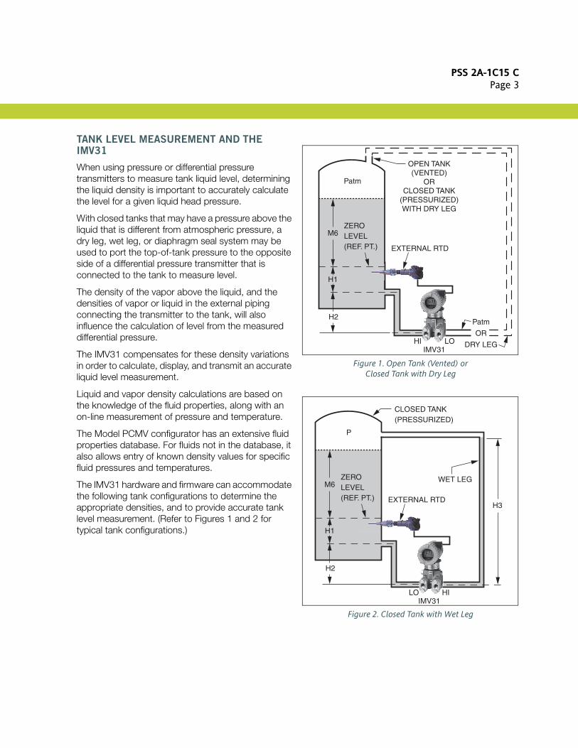
When using pressure or differential pressure transmitters to measure tank liquid level, determining the liquid density is important to accurately calculate the level for a given liquid head pressure.
With closed tanks that may have a pressure above the liquid that is different from atmospheric pressure, a dry leg, wet leg, or diaphragm seal system may be used to port the top-of-tank pressure to the opposite side of a differential pressure transmitter that is connected to the tank to measure level.
The density of the vapor above the liquid, and the densities of vapor or liquid in the external piping connecting the transmitter to the tank, will also influence the calculation of level from the measured differential pressure.
The IMV31 compensates for these density variations in order to calculate, display, and transmit an accurate liquid level measurement.
Liquid and vapor density calculations are based on the knowledge of the fluid properties, along with an on-line measurement of pressure and temperature.
The Model PCMV configurator has an extensive fluid properties database. For fluids not in the database, it also allows entry of known density values for specific fluid pressures and temperatures.
The IMV31 hardware and firmware can accommodate the following tank configurations to determine the appropriate densities, and to provide accurate tank level measurement. (Refer to Figures 1 and 2 for typical tank configurations.)
Figure 1. Open Tank (Vented) orClosed Tank with Dry Leg
Figure 2. Closed Tank with Wet Leg
Patm
OPEN TANK(VENTED)
ORCLOSED TANK
(PRESSURIZED)WITH DRY LEG
M6
H1
H2
ZEROLEVEL(REF. PT.)
HI LOIMV31
EXTERNAL RTD
Patm
OR
DRY LEG
CLOSED TANK(PRESSURIZED)
P
M6
H1
H2
ZEROLEVEL(REF. PT.)
LO HIIMV31
EXTERNAL RTDH3
WET LEG

PSS 2A-1C15 CPage 4
Referring to Figures 1 and 2, the following heights are user-configurable:
– H1 = Height from pressure tap to zero level point
– H2 = Height from transmitter connection to pressure tap
– H3 = Height from transmitter connection to top pressure connection.
Tanks may be open (vented), or they may be closed (pressurized).
Transmitter can be mounted at minimum level, or below minimum level. A level calibration feature provides tank level zeroing independent of transmitter elevation.
If tank is closed, the leg exiting the top-of-tank to transmitter can be either dry or wet.
– If it is a dry leg, then density of vapor in dry leg is calculated if configured for a pressure exceeding 20 psia; and used to correct level measurement for vapor density changes.
– If it is a wet leg, density of liquid in wet leg is calculated and used to correct the liquid level measurement.
If transmitter is mounted below minimum level, the leg to transmitter from the lower tank connection is assumed to have liquid in it, and its density calculated to correct the liquid level measurement.
One external RTD can be used for tank or leg fluid temperature measurement.
The temperature of the tank liquid and fluid (vapor or liquid) in both external legs going to each side of transmitter can be independently user-configured to be:
– User-entered constants– RTD temperature (tank liquid or leg fluid)– Electronics temperature (from internal sensor)– Sensor temperature (from internal sensor)– Calculated saturation temperature (water)
The temperatures of the vapor above the tank liquid and the tank liquid, are assumed to be equal.
For boiler drum level applications, the user does not have to enter fluid property data since the liquid and vapor are always water.
ANALOG OR DIGITAL TRANSMISSION
The 4 to 20 mA analog output can be assigned to any one of the following variables:
– Differential Pressure– Tank Pressure– Liquid Level– Tank Liquid Density(1)
Also, these variables, along with process, sensor, and electronics temperature, can be read digitally using the Model PCMV configurator or HART Communicator.
The digital output can be used for direct communication with an I/A Series System Fieldbus Module (FBM). With HART protocol, the above listed variables are digitally communicated to the system FBM along with the 4 to 20 mA current.
EASE OF INSTALLATION
Rotatable Topworks
– Allows installation in tight places– Positions indicator in preferred direction– Eases field retrofit
Two conduit connections
– Provide for easy wiring– Allow self-draining of condensation
Wiring guides and terminations
– Provide easy entry and plenty of space– Use large, rugged screw terminals for easy
wire termination
PROCESS CONNECTORS
Removable, gasketed connectors allow a wide range of selections, including 1/4 NPT, 1/2 NPT, Rc 1/4, Rc 1/2, and weld neck connectors.
(1) Density stated is at actual pressure and temperature, and based on known fluid parameters.
PSS 2A-1C15 CPage 5
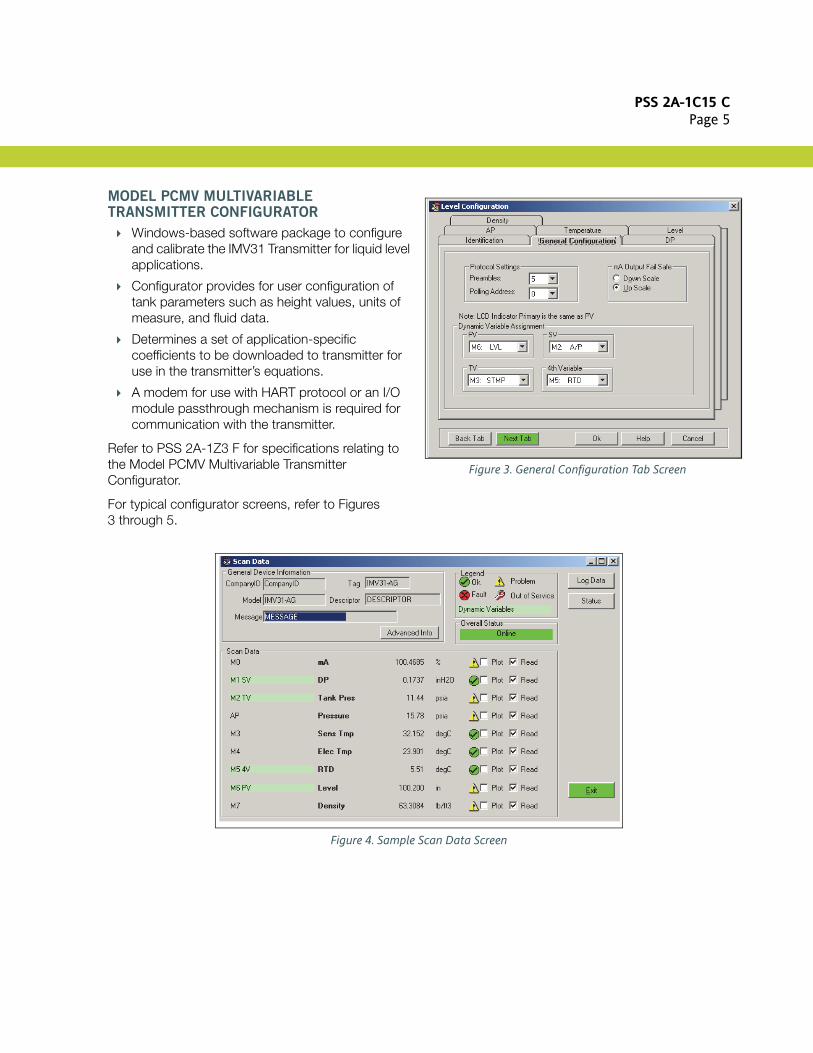
MODEL PCMV MULTIVARIABLE TRANSMITTER CONFIGURATOR
Windows-based software package to configure and calibrate the IMV31 Transmitter for liquid level applications.
Configurator provides for user configuration of tank parameters such as height values, units of measure, and fluid data.
Determines a set of application-specific coefficients to be downloaded to transmitter for use in the transmitter’s equations.
A modem for use with HART protocol or an I/O module passthrough mechanism is required for communication with the transmitter.
Refer to PSS 2A-1Z3 F for specifications relating to the Model PCMV Multivariable Transmitter Configurator.
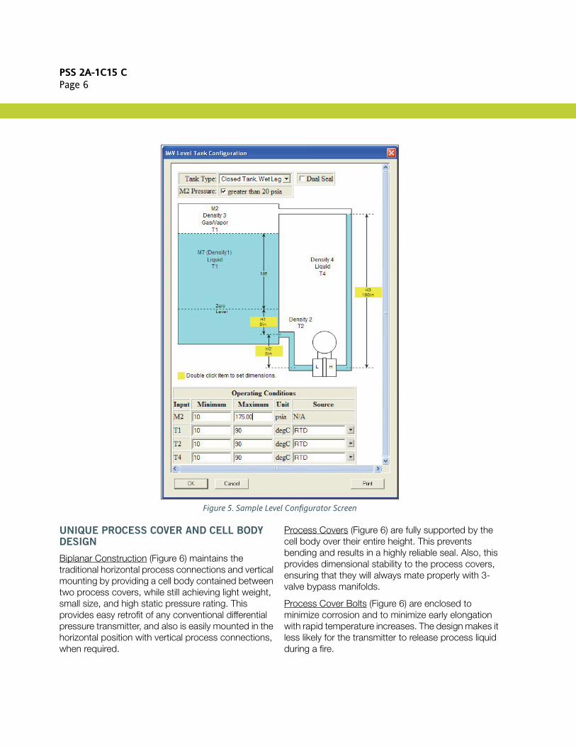
For typical configurator screens, refer to Figures 3 through 5.
Figure 3. General Configuration Tab Screen
Figure 4. Sample Scan Data Screen
PSS 2A-1C15 CPage 6
Figure 5. Sample Level Configurator Screen
UNIQUE PROCESS COVER AND CELL BODY DESIGN
Biplanar Construction (Figure 6) maintains the traditional horizontal process connections and vertical mounting by providing a cell body contained between two process covers, while still achieving light weight, small size, and high static pressure rating. This provides easy retrofit of any conventional differential pressure transmitter, and also is easily mounted in the horizontal position with vertical process connections, when required.
Process Covers (Figure 6) are fully supported by the cell body over their entire height. This prevents bending and results in a highly reliable seal. Also, this provides dimensional stability to the process covers, ensuring that they will always mate properly with 3-valve bypass manifolds.
Process Cover Bolts (Figure 6) are enclosed to minimize corrosion and to minimize early elongation with rapid temperature increases. The design makes it less likely for the transmitter to release process liquid during a fire.

PSS 2A-1C15 CPage 7
Process Cover Gaskets are ptfe as standard; ptfe provides nearly universal corrosion resistance, and eliminates the need to select and stock various elastomers to assure process compatibility.
ATEX Flameproof Design allows the transmitter to be installed in hazardous locations requiring ATEX Flameproof rating.
Light Weight provides ease of handling, installation, and direct mounting without requiring costly pipe stands.
Figure 6. Biplanar Construction
TRADITIONAL STRUCTURE
The traditional structure (Figure 7) utilizes the right angle design common to most differential pressure transmitters in use throughout the world. Process connections are oriented 90 degrees from the transmitter centerline.
This traditional structure makes it easy to retrofit any transmitters of similar design.
Figure 7. Vertical Mounting Showing Process Connections at 90 degrees
Figure 8. Vertical Mounting - Cavity Draining
Sensor cavity venting and draining is provided for both vertical and horizontal transmitter installation, using innovative tangential connections to the sensor cavity (Figures 8 and 9). Optional side vents are offered for sensor cavity venting in the upright position (Figure 10).
An extensive variety of process-wetted materials are available for the process covers on this highly versatile and widely used transmitter.
Figure 9. Horizontal Mounting - Cavity Venting and Self-Draining into Process Line
Figure 10. Vertical Mounting - Cavity Venting and Self-Draining into Process Line
CELL BODYENCLOSEDBOLTS
SUPPORTEDPROCESSCOVER
PROCESSCONNECTIONS
90˚
PROCESSCOVER DRAIN SCREW
VENT SCREW
OPTIONALSIDE VENTSHOWN
PLUG
PSS 2A-1C15 CPage 8 FUNCTIONAL SPECIFICATIONS
FUNCTIONAL SPECIFICATIONS
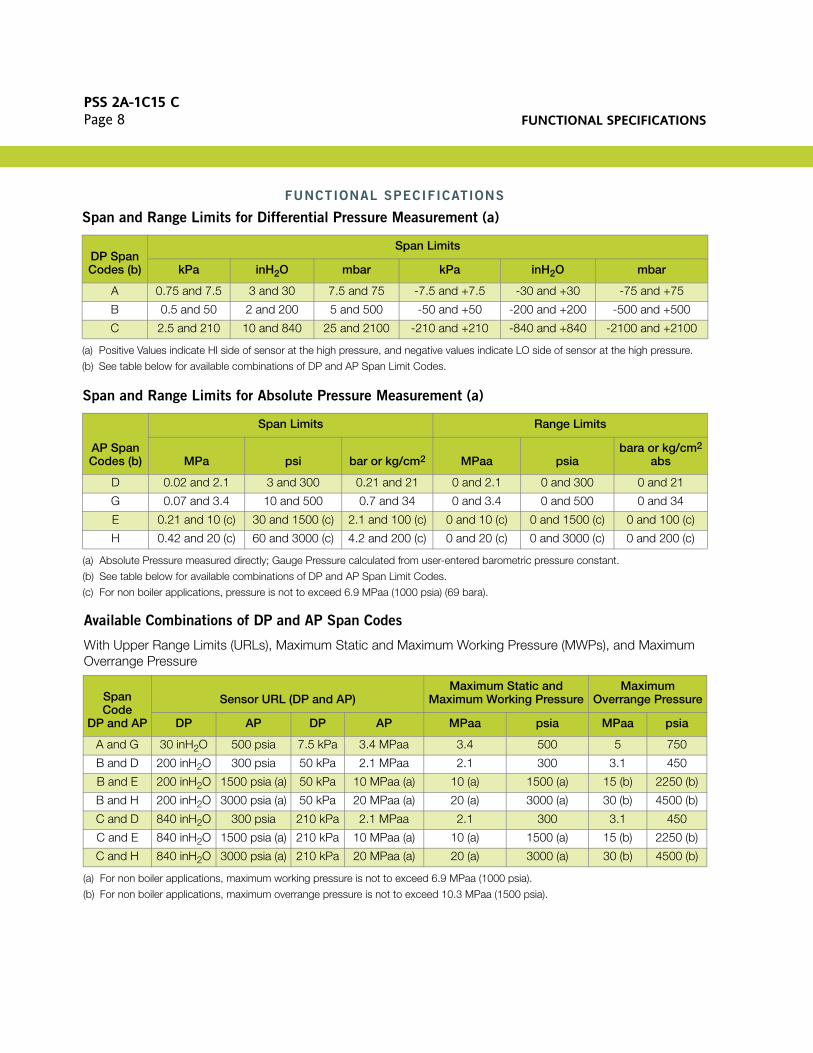
Available Combinations of DP and AP Span Codes
With Upper Range Limits (URLs), Maximum Static and Maximum Working Pressure (MWPs), and Maximum Overrange Pressure
Span and Range Limits for Differential Pressure Measurement (a)
(a) Positive Values indicate HI side of sensor at the high pressure, and negative values indicate LO side of sensor at the high pressure.
DP Span Codes (b)
(b) See table below for available combinations of DP and AP Span Limit Codes.
Span Limits
kPa inH2O mbar kPa inH2O mbar
A 0.75 and 7.5 3 and 30 7.5 and 75 -7.5 and +7.5 -30 and +30 -75 and +75
B 0.5 and 50 2 and 200 5 and 500 -50 and +50 -200 and +200 -500 and +500
C 2.5 and 210 10 and 840 25 and 2100 -210 and +210 -840 and +840 -2100 and +2100
Span and Range Limits for Absolute Pressure Measurement (a)
AP Span Codes (b)
Span Limits Range Limits
MPa psi bar or kg/cm2 MPaa psiabara or kg/cm2
abs
D 0.02 and 2.1 3 and 300 0.21 and 21 0 and 2.1 0 and 300 0 and 21
G 0.07 and 3.4 10 and 500 0.7 and 34 0 and 3.4 0 and 500 0 and 34
E 0.21 and 10 (c) 30 and 1500 (c) 2.1 and 100 (c) 0 and 10 (c) 0 and 1500 (c) 0 and 100 (c)
H 0.42 and 20 (c) 60 and 3000 (c) 4.2 and 200 (c) 0 and 20 (c) 0 and 3000 (c) 0 and 200 (c)
(a) Absolute Pressure measured directly; Gauge Pressure calculated from user-entered barometric pressure constant.
(b) See table below for available combinations of DP and AP Span Limit Codes.
(c) For non boiler applications, pressure is not to exceed 6.9 MPaa (1000 psia) (69 bara).
Span Code
DP and AP
Sensor URL (DP and AP)Maximum Static and
Maximum Working PressureMaximum
Overrange Pressure
DP AP DP AP MPaa psia MPaa psia
A and G 30 inH2O 500 psia 7.5 kPa 3.4 MPaa 3.4 500 5 750
B and D 200 inH2O 300 psia 50 kPa 2.1 MPaa 2.1 300 3.1 450
B and E 200 inH2O 1500 psia (a)
(a) For non boiler applications, maximum working pressure is not to exceed 6.9 MPaa (1000 psia).
50 kPa 10 MPaa (a) 10 (a) 1500 (a) 15 (b)
(b) For non boiler applications, maximum overrange pressure is not to exceed 10.3 MPaa (1500 psia).
2250 (b)
B and H 200 inH2O 3000 psia (a) 50 kPa 20 MPaa (a) 20 (a) 3000 (a) 30 (b) 4500 (b)
C and D 840 inH2O 300 psia 210 kPa 2.1 MPaa 2.1 300 3.1 450
C and E 840 inH2O 1500 psia (a) 210 kPa 10 MPaa (a) 10 (a) 1500 (a) 15 (b) 2250 (b)
C and H 840 inH2O 3000 psia (a) 210 kPa 20 MPaa (a) 20 (a) 3000 (a) 30 (b) 4500 (b)
FUNCTIONAL SPECIFICATIONSPSS 2A-1C15 C
Page 9
Output Signal and Configuration
One 4 to 20 mA output with HART Communications. This 4 to 20 mA output applicable to level (or other) measurements. When configured for multidrop applications, the mA signal is fixed at 4 mA to provide power to the device. Configurable with a HART Communicator, Model PCMV Configurator, or optional LCD indicator with on-board pushbuttons. Model PCMV Configurator required for complete level configuration.
Tank Outputs
Tank Pressure Differential Pressure Sensor Temperature (from Internal Sensor) Electronics Temperature (from Internal Sensor) Fluid Temperature (from External RTD) Tank Liquid Level Tank Liquid Density
Level Units
Inches Feet Millimeters Centimeters Meters
Adjustable Damping (DP and Pressure)
The transmitter response time is normally 1.0 s, or the electronically adjustable setting of 0.00 (none), 0.25, 0.50, 1, 2, 4, 8, 16, or 32 seconds, whichever is greater, for a 90% recovery from an 80% input step as defined in ANSI/ISA S51.1.
Field Wiring Reversal
No transmitter damage.
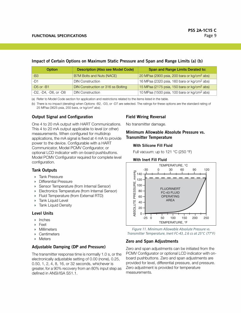
Minimum Allowable Absolute Pressure vs.
Transmitter Temperature
With Silicone Fill Fluid
Full vacuum: up to 121 °C (250 °F)
With Inert Fill Fluid
Figure 11. Minimum Allowable Absolute Pressure vs. Transmitter Temperature, Inert FC-43, 2.6 cs at 25°C (77°F)
Zero and Span Adjustments
Zero and span adjustments can be initiated from the PCMV Configurator or optional LCD indicator with on-board pushbuttons. Zero and span adjustments are provided for level, differential pressure, and pressure. Zero adjustment is provided for temperature measurements.
Impact of Certain Options on Maximum Static Pressure and Span and Range Limits (a) (b)
Option Description (Also see Model Code) Span and Range Limits Derated to:
-B3 B7M Bolts and Nuts (NACE) 20 MPaa (2900 psia, 200 bara or kg/cm2 abs)
-D1 DIN Construction 16 MPaa (2320 psia, 160 bara or kg/cm2 abs)
-D5 or -B1 DIN Construction or 316 ss Bolting 15 MPaa (2175 psia, 150 bara or kg/cm2 abs)
-D2, -D4, -D6, or -D8 DIN Construction 10 MPaa (1500 psia, 100 bara or kg/cm2 abs)
(a) Refer to Model Code section for application and restrictions related to the items listed in the table.
(b) There is no impact (derating) when Options -B2, -D3, or -D7 are selected. The ratings for these options are the standard rating of 25 MPaa (3625 psia, 250 bara, or kg/cm2 abs).
TEMPERATURE, °F
TEMPERATURE, °C
AB
SO
LUT
E P
RE
SS
UR
E, m
mH
g -30 0 30 60 90 120
-25 0 50 100 150 200 250
140
120
100
80
60
40
20
0
FLUORINERTFC-43 FLUIDOPERATING
AREA
PSS 2A-1C15 CPage 10 FUNCTIONAL SPECIFICATIONS
Zeroing for Nonzero-Based Ranges
Dual Function Zeroing from the optional LCD indicator pushbuttons allows differential pressure zeroing with either zero differential or LRV differential applied. This simplifies position effect zeroing. Also, the PCMV or HART Communicator provides zeroing at any user-entered value.
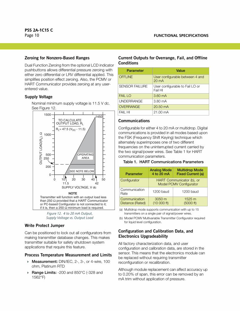
Supply Voltage
Nominal minimum supply voltage is 11.5 V dc. See Figure 12.
Figure 12. 4 to 20 mA Output,Supply Voltage vs. Output Load
Write Protect Jumper
Can be positioned to lock out all configurators from making transmitter database changes. This makes transmitter suitable for safety shutdown system applications that require this feature.
Process Temperature Measurement and Limits
Measurement: DIN/IEC, 2-, 3-, or 4-wire, 100 ohm, Platinum RTD
Range Limits: -200 and 850°C (-328 and 1562°F)
Current Outputs for Overrange, Fail, and Offline
Conditions
Communications
Configurable for either 4 to 20 mA or multidrop. Digital communications is provided in all modes based upon the FSK (Frequency Shift Keying) technique which alternately superimposes one of two different frequencies on the uninterrupted current carried by the two signal/power wires. See Table 1 for HART communication parameters.
Configuration and Calibration Data, and
Electronics Upgradeability
All factory characterization data, and user configuration and calibration data, are stored in the sensor. This means that the electronics module can be replaced without requiring transmitter reconfiguration or recalibration.
Although module replacement can affect accuracy up to 0.20% of span, this error can be removed by an mA trim without application of pressure.
1500
1000
500
200
0
OU
TP
UT
LO
AD
(RL)
, Ω
TO CALCULATEOUTPUT LOAD, RL
1450
OPERATINGAREA
0 10 20 30 40 5011.5 42
SUPPLY VOLTAGE, V dc
SEE NOTE BELOW
NOTETransmitter will function with an output load lessthan 250 Ω provided that a HART Communicator or PC-based Configurator is not connected to it; if it is, then a 250 Ω minimum load is required.
RL= 47.5 (VDC - 11.5)
250
Parameter Value
OFFLINE User configurable between 4 and 20 mA
SENSOR FAILURE User configurable to Fail LO or Fail HI
FAIL LO 3.60 mA
UNDERRANGE 3.80 mA
OVERRANGE 20.50 mA
FAIL HI 21.00 mA
Table 1. HART Communications Parameters
ParameterAnalog Mode
4 to 20 mAMultidrop ModeFixed Current (a)
(a) Multidrop mode supports communication with up to 15 transmitters on a single pair of signal/power wires.
Configurator HART Communicator (b), orModel PCMV Configurator
(b) Model PCMV Multivariable Transmitter Configurator required for liquid level configuration.
Communication Rate 1200 baud 1200 baud
Communication Distance (Rated)
3050 m(10 000 ft)
1525 m(5000 ft)
FUNCTIONAL SPECIFICATIONSPSS 2A-1C15 C
Page 11
Configuration Capability
NOTE
Numerous parameters can be configured and/or displayed, such as electronic damping, failsafe direction, transmitter calibration, tag data, etc. See applicable configuration documents for details.
Available Units for Calibrated Range
Option -C2: Optional Custom Factory
Configuration
Invensys recommends that the IMV31 be factory configured by selecting Option -C2, and completing the Multivariable Configuration Wizard before entering the order. If Option -C2 is not selected, a standard default configuration will be provided. The user will then need to completely configure the transmitter for liquid level applications using the Model PCMV.
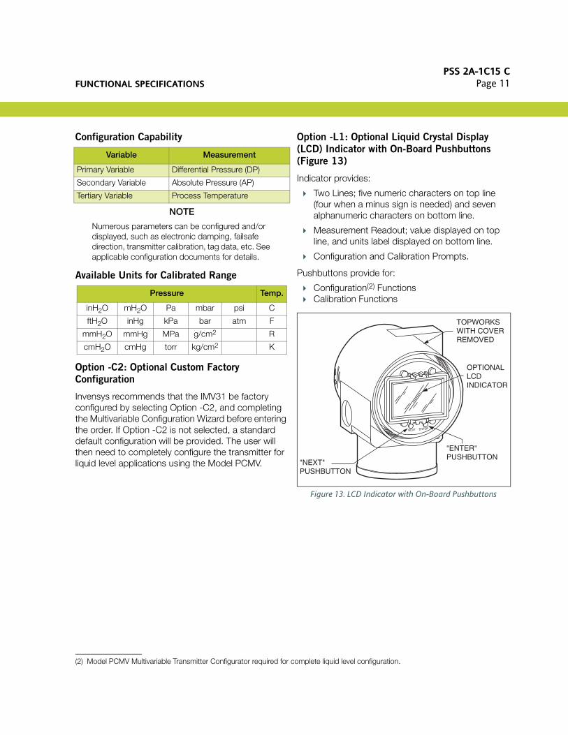
Option -L1: Optional Liquid Crystal Display
(LCD) Indicator with On-Board Pushbuttons
(Figure 13)
Indicator provides:
Two Lines; five numeric characters on top line (four when a minus sign is needed) and seven alphanumeric characters on bottom line.
Measurement Readout; value displayed on top line, and units label displayed on bottom line.
Configuration and Calibration Prompts.
Pushbuttons provide for:
Configuration(2) Functions Calibration Functions
Figure 13. LCD Indicator with On-Board Pushbuttons
Variable Measurement
Primary Variable Differential Pressure (DP)
Secondary Variable Absolute Pressure (AP)
Tertiary Variable Process Temperature
Pressure Temp.
inH2O mH2O Pa mbar psi C
ftH2O inHg kPa bar atm F
mmH2O mmHg MPa g/cm2 R
cmH2O cmHg torr kg/cm2 K
(2) Model PCMV Multivariable Transmitter Configurator required for complete liquid level configuration.
TOPWORKSWITH COVERREMOVED
OPTIONALLCD INDICATOR
"ENTER"PUSHBUTTON
"NEXT"PUSHBUTTON
NEXT ENTER
PSS 2A-1C15 CPage 12 FUNCTIONAL SPECIFICATIONS
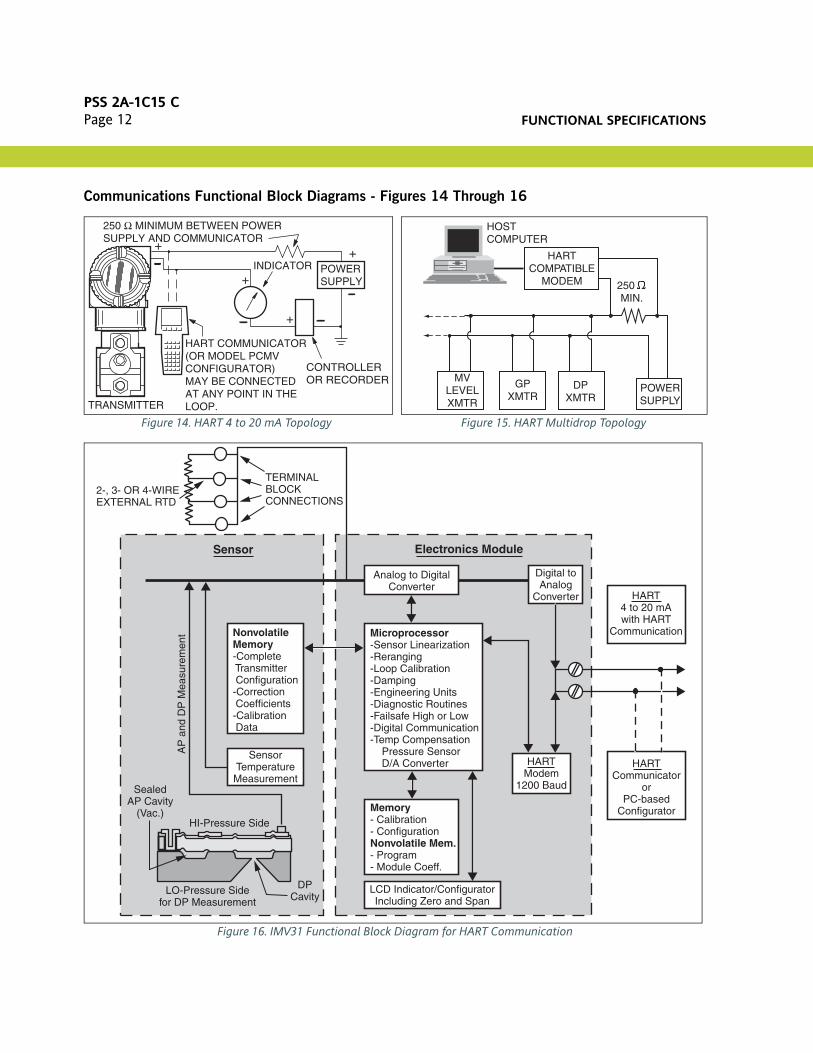
Communications Functional Block Diagrams - Figures 14 Through 16
Figure 14. HART 4 to 20 mA Topology
Figure 15. HART Multidrop Topology
Figure 16. IMV31 Functional Block Diagram for HART Communication
INDICATOR
TRANSMITTER
HART COMMUNICATOR(OR MODEL PCMVCONFIGURATOR)MAY BE CONNECTEDAT ANY POINT IN THELOOP.
CONTROLLEROR RECORDER
+
+
+
+
250 Ω MINIMUM BETWEEN POWERSUPPLY AND COMMUNICATOR
POWERSUPPLY
HARTCOMPATIBLE
MODEM
GPXMTR
POWERSUPPLY
DPXMTR
MVLEVELXMTR
250 MIN.
HOST COMPUTER
2-, 3- OR 4-WIREEXTERNAL RTD
TERMINALBLOCKCONNECTIONS
NonvolatileMemory-Complete Transmitter Configuration-Correction Coefficients-Calibration Data
SensorTemperatureMeasurement
Analog to DigitalConverter
Digital toAnalog
Converter
Microprocessor-Sensor Linearization-Reranging-Loop Calibration-Damping-Engineering Units-Diagnostic Routines-Failsafe High or Low-Digital Communication-Temp Compensation Pressure Sensor D/A Converter
Memory- Calibration- ConfigurationNonvolatile Mem.- Program- Module Coeff.
LCD Indicator/ConfiguratorIncluding Zero and Span
HARTModem
1200 Baud
HARTCommunicator
orPC-based
Configurator
HART4 to 20 mAwith HART
Communication
Electronics ModuleSensor
LO-Pressure Sidefor DP Measurement
HI-Pressure Side
DPCavity
SealedAP Cavity
(Vac.)
AP
and
DP
Mea
sure
men
t

OPERATING, STORAGE, AND TRANSPORTATION CONDITIONS
PSS 2A-1C15 CPage 13
OPERATING, STORAGE, AND TRANSPORTATION CONDITIONS
InfluenceReference Conditions
Normal Operating Conditions (a) (b)
(a) When DIN Construction Options -D2-/D4/-D6/-D8 are used, temperature limits are 0 and 60°C (32 and 140°F).
(b) Normal Operating Conditions and Operative Limits are defined per ANSI/ISA 51.1-1979 (R1993).
Operative Limits (a) (b)Transportation/
Storage Limits
Sensor Body Temperaturew/Silicone Fill Fluid
w/Inert Fill Fluid
24 ±2°C(75 ±3°F)
24 ±2°C(75 ±3°F)
-29 to + 82°C(-20 to +180°F)
-29 to + 82°C(-20 to +180°F)
-46 and +121°C (c)(-50 and +250°F) (c)
-29 and +121°C(-20 and +250°F)
(c) Selection of Option -J extends the low temperature operative limit of transmitters with silicone filled sensors down to -50°C (-58°F). Performance is not assured below -29°C. Sensor damage may occur if process is frozen.
-54 and +85°C(-65 and +185°F)
-50 and +85°C(-58 and +185°F)
Electronics Temperature
with LCD Indicator (d)
(d) Although the LCD will not be damaged at any temperature within the “Transportation/ Storage Limits”, updates will be slowed and readability decreased at temperatures outside the “Normal Operating Conditions”.
24 ±2°C(75 ±3°F)
24 ±2°C(75 ±3°F)
-29 to + 82 °C(-20 to +180 °F)
-20 to + 82 °C(-4 to +180 °F)
-40 and +85°C (e)(-40 and +185°F) (e)
-29 and +85°C (e)(-20 and +185°F) (e)
(e) Refer to the Electrical Safety Specifications section for a restriction in ambient temperature limits with certain electrical certifications.
-54 and +85°C(-65 and +185°F)
-54 and +85°C(-65 and +185°F)
Relative Humidity (f)
(f) With topworks cover on and conduit entrances sealed.
50 ±10% 0 to 100% 0 and 100% 0 and 100%Noncondensing
Supply Voltage – mA Output 30 ±0.5 V dc 11.5 to 42 V dc 11.5 and 42 V dc Not Applicable
Output Load – mA Output 650 Ω 0 to 1450 Ω (g)
(g) See Figure 12 for minimum load required for proper HART communication.
0 and 1450 Ω (g) Not Applicable
Vibration 1 m/s2
(0.1 “g”)6.3 mm (0.25 in) Double Amplitude:
from 5 to 15 Hz with Aluminum Housingfrom 5 to 9 Hz with 316 ss Housing
0 to 30 m/s2 (0 to 3 “g”) from 15 to 500 Hzwith Aluminum Housing;
0 to 10 m/s2 (0 to 1 “g”) from 9 to 500 Hzwith 316 ss Housing
11 m/s2
(1.1 “g”)from 2.5 to 5 Hz
(in Shipping Package)
Mounting Position Upright or Horizontal (h)
(h) Sensor process wetted diaphragms in a vertical plane.
No Limit Not Applicable
PSS 2A-1C15 CPage 14 PERFORMANCE SPECIFICATIONS
PERFORMANCE SPECIFICATIONS
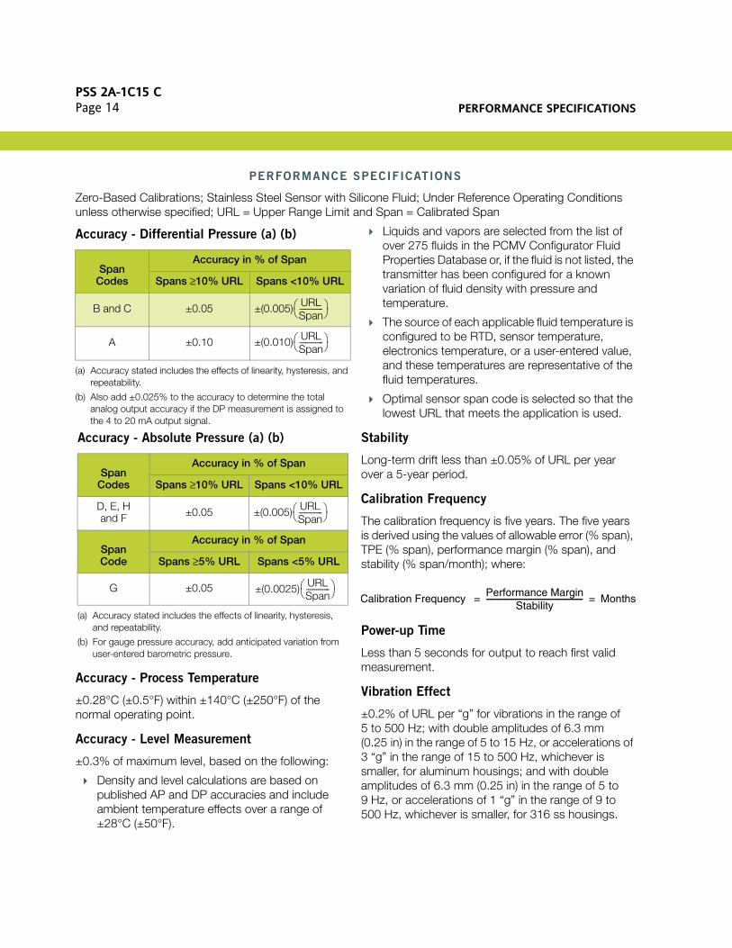
Zero-Based Calibrations; Stainless Steel Sensor with Silicone Fluid; Under Reference Operating Conditions unless otherwise specified; URL = Upper Range Limit and Span = Calibrated Span
Accuracy - Process Temperature
±0.28°C (±0.5°F) within ±140°C (±250°F) of the normal operating point.
Accuracy - Level Measurement
±0.3% of maximum level, based on the following:
Density and level calculations are based on published AP and DP accuracies and include ambient temperature effects over a range of ±28°C (±50°F).
Liquids and vapors are selected from the list of over 275 fluids in the PCMV Configurator Fluid Properties Database or, if the fluid is not listed, the transmitter has been configured for a known variation of fluid density with pressure and temperature.
The source of each applicable fluid temperature is configured to be RTD, sensor temperature, electronics temperature, or a user-entered value, and these temperatures are representative of the fluid temperatures.
Optimal sensor span code is selected so that the lowest URL that meets the application is used.
Stability
Long-term drift less than ±0.05% of URL per year over a 5-year period.
Calibration Frequency
The calibration frequency is five years. The five years is derived using the values of allowable error (% span), TPE (% span), performance margin (% span), and stability (% span/month); where:
Power-up Time
Less than 5 seconds for output to reach first valid measurement.
Vibration Effect
±0.2% of URL per “g” for vibrations in the range of 5 to 500 Hz; with double amplitudes of 6.3 mm (0.25 in) in the range of 5 to 15 Hz, or accelerations of 3 “g” in the range of 15 to 500 Hz, whichever is smaller, for aluminum housings; and with double amplitudes of 6.3 mm (0.25 in) in the range of 5 to 9 Hz, or accelerations of 1 “g” in the range of 9 to 500 Hz, whichever is smaller, for 316 ss housings.
Accuracy - Differential Pressure (a) (b)
(a) Accuracy stated includes the effects of linearity, hysteresis, and repeatability.
(b) Also add ±0.025% to the accuracy to determine the total analog output accuracy if the DP measurement is assigned to the 4 to 20 mA output signal.
SpanCodes
Accuracy in % of Span
Spans ≥10% URL Spans <10% URL
B and C ±0.05
A ±0.10
Accuracy - Absolute Pressure (a) (b)
(a) Accuracy stated includes the effects of linearity, hysteresis, and repeatability.
(b) For gauge pressure accuracy, add anticipated variation from user-entered barometric pressure.
SpanCodes
Accuracy in % of Span
Spans ≥10% URL Spans <10% URL
D, E, H and F ±0.05
SpanCode
Accuracy in % of Span
Spans ≥5% URL Spans <5% URL
G ±0.05
±(0.005) URLSpan------------
±(0.010) URLSpan------------
±(0.005) URLSpan------------
±(0.0025) URLSpan------------
Calibration Frequency Performance Margin
Stability------------------------------------------------------ Months= =

PHYSICAL SPECIFICATIONSPSS 2A-1C15 C
Page 15
RFI Effect
The output error is less than 0.1% of span for radio frequencies in the range of 27 to 1000 MHz and field intensity of 30 V/m when the transmitter is properly installed with shielded conduit and grounding, and housing covers are in place. (Per IEC Std. 61000-4-3.)
Supply Voltage Effect
Output changes less than 0.005% of span for each 1 V change within the specified supply voltage requirements. See Figure 12.
Ambient Temperature Effect
Total effect for both absolute and differential pressure for a 28°C (50°F) change within Normal Operating Condition Limits is ±(0.03% URL + 0.06% span); except the effect on differential pressure for DP Span Code A is ±(0.18% URL + 0.025% span). Also for AP Span Code H, the effect is ±(0.02% URL + 0.06% span).
Position Effect
Transmitter may be mounted in any position. Any zero effect caused by mounting position can be eliminated by rezeroing. There is no span effect.
Switching and Indirect Lightning Transients
The transmitter can withstand a transient surge up to 2000 V common mode or 1000 V normal mode without permanent damage. Output shift is <1.0%. (Per ANSI/IEEE C62.41-1980 and IEC Std. 61000-4-5.)
Electromagnetic Compatibility
Complies with NAMUR NE 21 Interference Immunity Requirement (EMC)
Complies with electromagnetic compatibility requirements of European EMC Directive 89/336/EEC by conforming to following CENELEC and IEC Standards: EN 50081-2, EN 50082-2, IEC 61000-4-2 through 61000-4-6.
Static Pressure Effect on Differential Pressure
The zero and span shift for a 0.7 MPa, 100 psi, change in static pressure is:
Zero Shift
Span Shift
±0.01% of Reading
PHYSICAL SPECIFICATIONS
Process Cover and Connector Material (Process
Wetted)
316 ss or nickel alloy (equivalent to Hastelloy® C(3)), as specified.
Process Cover and Process Connection Gaskets
Glass filled ptfe (Chemloy)
Process Cover Bolts and Nuts
ASTM A193, Grade B7 high strength alloy steel for bolts, and ASTM A194 Grade 2H high strength alloy steel for nuts are standard. Options include NACE Class II - B7M bolting, 17-4 ss bolting, and 316 ss bolting. NACE Class II is recommended when bolting is directly exposed to sour environments, or is buried, insulated, or otherwise denied atmospheric exposures.
Span Limit CodeZero Shift for a
0.7 MPa (100 psi) Change:
DP AP in % of URL
A G ±0.050
B D ±0.007
B E ±0.010
B H ±0.010
C D ±0.002
C E ±0.004
C H ±0.004
(3) Hastelloy is a registered trademark of Haynes International, Inc.
PSS 2A-1C15 CPage 16 PHYSICAL SPECIFICATIONS
Sensor Material (Process Wetted)
316L ss or nickel alloy (equivalent to Hastelloy® C), as specified
Sensor Fill Fluids
Silicone Oil or Inert (FC-43)
Environmental Protection
Transmitter is dusttight and weather proof per IEC IP66 and provides the environmental and corrosion resistant protection of NEMA Type 4X.
Electronics Module
Printed wiring assemblies are conformally coated for moisture and dust protection.
Electronics Housing and Housing Covers
Housing has two compartments to separate the electronics from the field connections. The housing and covers are made from low copper, die-cast aluminum alloy with an epoxy finish, or from 316 ss. Buna-N O-ring seals are used to seal the threaded housing covers, housing neck, and terminal block.
Electrical Connections
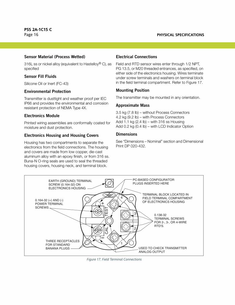
Field and RTD sensor wires enter through 1/2 NPT, PG 13.5, or M20 threaded entrances, as specified, on either side of the electronics housing. Wires terminate under screw terminals and washers on terminal block in the field terminal compartment. Refer to Figure 17.
Mounting Position
The transmitter may be mounted in any orientation.
Approximate Mass
3.5 kg (7.8 lb) – without Process Connectors4.2 kg (9.2 lb) – with Process ConnectorsAdd 1.1 kg (2.4 lb) – with 316 ss HousingAdd 0.2 kg (0.4 lb) – with LCD Indicator Option
Dimensions
See “Dimensions – Nominal” section and Dimensional Print DP 020-432.
Figure 17. Field Terminal Connections
+
TE
ST
CA
L
4
3
2
1
EARTH (GROUND) TERMINALSCREW (0.164-32) ON ELECTRONICS HOUSING
0.164-32 (+) AND (-)POWER TERMINALSCREWS
THREE RECEPTACLESFOR STANDARDBANANA PLUGS
PC-BASED CONFIGURATORPLUGS INSERTED HERE
TERMINAL BLOCK LOCATED INFIELD TERMINAL COMPARTMENTOF ELECTRONICS HOUSING
0.138-32TERMINAL SCREWS FOR 2-, 3-, OR 4-WIRERTD'S.
USED TO CHECK TRANSMITTERANALOG OUTPUT

ELECTRICAL SAFETY SPECIFICATIONSPSS 2A-1C15 C
Page 17
ELECTRICAL SAFETY SPECIFICATIONS
Transmitter has been designed to meet the electrical safety descriptions listed. Contact Invensys for information or status of testing laboratory approvals or certifications.
Refer to applicable Instruction Manual for application conditions and connectivity requirements.
Testing Laboratory, Types of Protection, and Area Classification Application Conditions
Elec. Safety Design Code
ATEX flameproof; II 2 GD, EEx d IIC, Zone 1. Temperature Class T6, T85°C;Ta = -40 to +80°C
D
ATEX intrinsically safe; II 1 GD, EEx ia IIC, Zone 0; or II 1/2 GD, EEx ib IIC, Zone 0/1.
Temperature Class T4 at 80°C, T5 at 40°C, and T6 at 40°C maximum ambient.
E
ATEX protection n; II 3 GD, EEx nL IIC, Zone 2. Temperature Class T4 at 80°C, T5 at 70°C, and T6 at 40°C maximum ambient.
N
ATEX multiple certifications, ia & ib, d, and n. Refer to Codes D, E and N for details.
Applies to Codes D, E, and N. M (a)
(a) When selecting ATEX Safety Design Code M, the user must permanently mark (check off in rectangle block on data plate) one type of protection only (ia and ib, d, or n). Do not change this mark.
CSA intrinsically safe for Class I, Division 1, Groups A, B, C, and D; Class II, Division 1, Groups E, F, and G; Class III, Division 1.
Temperature Class T4A at 40°C and T3C at 85°C maximum ambient.
C
CSA Zone certified intrinsically safe Ex ia IIC and energy limited Ex nA II.
Temperature Class T4 at 40°C, and T3 at 85°C maximum ambient.
C
CSA explosionproof for Class I, Division 1, Groups B, C, and D; and dust-ignitionproof apparatus for Class II, Division 1, Groups E, F, and G; and Class III, Division 1.
Maximum Ambient Temperature 85°C. C
CSA suitable for Class I, Division 2, Groups A, B, C, and D; Class II, Division 2, Groups F and G; and Class III, Division 2.
Temperature Class T4A at 40°C and T3C at 85°C maximum ambient.
C
CSA field device zone certified flameproof Ex d IIC. Also, all certifications of Code C above.
Maximum Ambient Temperature 85°C. B
FM intrinsically safe for Class I, Division 1, Groups A, B, C, and D; Class II, Division 1, Groups E, F, and G; and Class III, Division 1.
Temperature Class T4A at 85°C maximum ambient.
F
FM Zone approved intrinsically safe AEx ia IIC. Temperature Class T4 at 85°C maximum ambient.
F
FM explosionproof for Class I, Division 1, Groups B, C, and D; and dust-ignitionproof apparatus for Class II, Division 1, Groups E, F, and G; and Class III, Division 1.
Temperature Class T6 at 80°C and T5 at 85°C maximum ambient.
F
FM nonincendive apparatus for Class I, Division 2, Groups A, B, C, and D; Class II, Division 2, Groups F and G; and Class III, Division 2.
Temperature Class T4A at 85°C maximum ambient.
F
FM field device zone certified flameproof AEx d IIC. Also, all certifications of Code F above.
Temperature Class T6 at 80°C and T5 at 85°C maximum ambient.
G
IECEx flameproof: Ex d IIC T6 Ta=80°C, T5 Ta=85°CAmbient Temperature -20 to +85°C
V

PSS 2A-1C15 CPage 18 MODEL CODE
MODEL CODE
Description ModelMultivariable Transmitter IMV31
Electronics Versions and Output Signal
Intelligent; Digital HART and 4 to 20 mA dc (Version -T) -T
Structure Code - Process Covers, Sensor Material, and Sensor Fill Fluid
With Traditional Structure
Covers Sensor Fill Fluid316 ss 316L ss Silicone316 ss 316L ss Inert
2223
316 ss Nickel alloy (a) Silicone316 ss Nickel alloy (a) Inert
2627
Nickel alloy (a) Nickel alloy (a) SiliconeNickel alloy (a) Nickel alloy (a) Inert
4647
Span Limits - Differential Pressure (DP) Measurement
kPa inH2O mbar Available with: (b)0.75 and 7.5 3 and 30 7.5 and 75 AP Code G only0.5 and 50 2 and 200 5 and 500 AP Codes D, E, and H only2.5 and 210 10 and 840 25 and 2100 AP Codes D, E, and H only
ABC
Span Limits - Absolute Pressure (AP) Measurement (Absolute Measured; Gauge Calculated)
MPaa psia bara or kg/cm2 abs Available with: (b)0.02 and 2.1 3 and 300 0.21 and 21 DP Codes B and C only0.07 and 3.5 10 and 500 0.7 and 35 DP Codes L and A only0.21 and 10 (c) 30 and 1500 (c) 2.1 and 100 (c) DP Codes B and C only0.42 and 20 (c) 60 and 3000 (c) 4.2 and 200 (c) DP Codes B and C only
DGEH
Process Connector Type (Material Same as Process Cover Material)
None, Covers tapped for 1/4 NPT1/4 NPT (Not with Structure Codes 46 and 47 - Nickel alloy (a) Process Covers)1/2 NPTRc 1/4 (Not with Structure Codes 46 and 47) - Nickel alloy (a) Process CoversRc 1/21/2 Schedule 80 Welding Neck (Not with Structure Codes 46 and 47 - Nickel alloy (a) Process Covers)
012346
Conduit Connection and Housing Material
1/2 NPT Connection, Aluminum HousingPG 13.5 Connection, Aluminum Housing (Available with Electrical Safety Codes E, D, M, and N only)1/2 NPT Connection, 316 ss HousingPG 13.5 Connection, 316 ss Housing (Available with Electrical Safety Codes E, D, M, and N only)M20 Connection, Aluminum Housing (Available with Electrical Safety Codes E, D, M, and N only)M20 Connection, 316 ss Housing (Available with Electrical Safety Codes E, D, M, and N only)
123456

MODEL CODEPSS 2A-1C15 C
Page 19
Electrical Safety (Also see Electrical Safety Specifications section)
ATEX II 1 GD, EEx ia IIC, Zone 0; or II 1/2 GD, EEx ib IIC, Zone 0/Zone 1ATEX II 2 GD, EEx d IIC, Zone 1 (d)ATEX II 3 GD, EEx nL IIC, Zone 2ATEX Multiple Certifications; with Electronics Version -T only (includes ATEX Codes E, D, and N) (d)
(See Electrical Safety Specifications section for user marking)
EDNM
CSA Certified Division 1 intrinsically safe, explosionproof, dust-ignitionproof, and Division 2, Classes I, II, and III. Also zone certified Ex ia IIC and Ex nA IIC.
CSA Zone Certified Ex d IIC; and all certifications of Code C above (d).
C
B
FM approved Division 1 intrinsically safe, explosionproof, dust-ignitionproof, and nonincendive, Division 2, Classes I, II, and III. Also zone approved intrinsically safe AEx ia IIC.
FM approved AEx d IIC; and also all approvals of Code F above (d).
F
G
IECEx flameproof; Ex d IIC V
Optional Selections (e)
Refer to descriptions that follow.
Mounting Bracket Set
Painted Steel Bracket with Plated Steel BoltsStainless Steel Bracket with Stainless Steel Bolts
-M1-M2
Digital Indicator with Pushbuttons
Digital Indicator, Pushbuttons, and Window Cover -L1
DIN 19213 Construction used with Process Connector Code “0” and 316 ss Process Covers Only (f)
Process CoverCover Screw Connector ScrewType Material Size MaterialSingle Ended Steel M10 (by User) –Double Ended (g) Steel M10 Steel
(Blind Kidney Flange on back)Single Ended Steel 7/16 (by User) –Double Ended (g) Steel 7/16 Steel
(Blind Kidney Flange on back)Single Ended 316 ss 7/16 (by User) –Double Ended (g) 316 ss 7/16 316 ss
(Blind Kidney Flange on back)Single Ended 17-4 ss 7/16 (by User) –Double Ended (g) 17-4 ss 7/16 17-4 ss
(Blind Kidney Flange on back)
-D1-D2
-D3-D4
-D5-D6
-D7-D8
Cleaning and Preparation
Unit Degreased - for Silicone Filled Sensors Only(Not for Oxygen/Chlorine/Other Fluids that may react with Silicone)
Cleaned and Prepared for Oxygen Service - for Inert Filled Sensors OnlyCleaned and Prepared for Chlorine Service - for Inert Filled Sensors Only (h)
-X1
-X2-X3
Bolting for Process Covers/Connectors (i)
316 ss Bolts and Nuts17-4 ss Bolts and Nuts (h)B7M Bolts and Nuts (j)
-B1-B2-B3
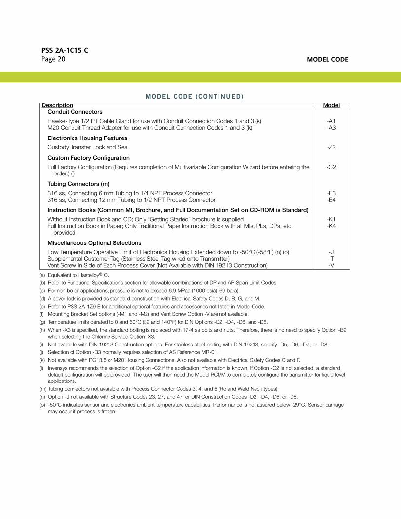
MODEL CODE (CONTINUED)
Description Model
PSS 2A-1C15 CPage 20 MODEL CODE
Conduit Connectors
Hawke-Type 1/2 PT Cable Gland for use with Conduit Connection Codes 1 and 3 (k)M20 Conduit Thread Adapter for use with Conduit Connection Codes 1 and 3 (k)
-A1-A3
Electronics Housing Features
Custody Transfer Lock and Seal -Z2
Custom Factory Configuration
Full Factory Configuration (Requires completion of Multivariable Configuration Wizard before entering the order.) (l)
-C2
Tubing Connectors (m)
316 ss, Connecting 6 mm Tubing to 1/4 NPT Process Connector 316 ss, Connecting 12 mm Tubing to 1/2 NPT Process Connector
-E3-E4
Instruction Books (Common MI, Brochure, and Full Documentation Set on CD-ROM is Standard)
Without Instruction Book and CD; Only “Getting Started” brochure is suppliedFull Instruction Book in Paper; Only Traditional Paper Instruction Book with all MIs, PLs, DPs, etc.
provided
-K1-K4
Miscellaneous Optional Selections
Low Temperature Operative Limit of Electronics Housing Extended down to -50°C (-58°F) (n) (o)Supplemental Customer Tag (Stainless Steel Tag wired onto Transmitter)Vent Screw in Side of Each Process Cover (Not Available with DIN 19213 Construction)
-J-T-V
(a) Equivalent to Hastelloy® C.
(b) Refer to Functional Specifications section for allowable combinations of DP and AP Span Limit Codes.
(c) For non boiler applications, pressure is not to exceed 6.9 MPaa (1000 psia) (69 bara).
(d) A cover lock is provided as standard construction with Electrical Safety Codes D, B, G, and M.
(e) Refer to PSS 2A-1Z9 E for additional optional features and accessories not listed in Model Code.
(f) Mounting Bracket Set options (-M1 and -M2) and Vent Screw Option -V are not available.
(g) Temperature limits derated to 0 and 60°C (32 and 140°F) for DIN Options -D2, -D4, -D6, and -D8.
(h) When -X3 is specified, the standard bolting is replaced with 17-4 ss bolts and nuts. Therefore, there is no need to specify Option -B2 when selecting the Chlorine Service Option -X3.
(i) Not available with DIN 19213 Construction options. For stainless steel bolting with DIN 19213, specify -D5, -D6, -D7, or -D8.
(j) Selection of Option -B3 normally requires selection of AS Reference MR-01.
(k) Not available with PG13.5 or M20 Housing Connections. Also not available with Electrical Safety Codes C and F.
(l) Invensys recommends the selection of Option -C2 if the application information is known. If Option -C2 is not selected, a standard default configuration will be provided. The user will then need the Model PCMV to completely configure the transmitter for liquid level applications.
(m) Tubing connectors not available with Process Connector Codes 3, 4, and 6 (Rc and Weld Neck types).
(n) Option -J not available with Structure Codes 23, 27, and 47, or DIN Construction Codes -D2, -D4, -D6, or -D8.
(o) -50°C indicates sensor and electronics ambient temperature capabilities. Performance is not assured below -29°C. Sensor damage may occur if process is frozen.
MODEL CODE (CONTINUED)
Description Model

SUGGESTED RFQ SPECIFICATIONSPSS 2A-1C15 C
Page 21
SUGGESTED RFQ SPECIFICATIONS
The manufacturer shall provide field-mounted multivariable transmitter(s) for density-compensated level measurement featuring remote digital communications capability for measuring tank pressure, differential pressure, and fluid temperature, and transmitting a 4 to 20 mA dc and/or digital output signal (software selectable) for use in a standard two-wire dc supply voltage system. The transmitted signals shall be used with a PC-based configurator for transmission of calculated density-compensated liquid level measurements. The specifications for this Multivariable transmitter are as follows:
Communication Protocol: HART, digital and/or 4 to 20 mA dc output signal
Remote Communications: Must not interfere with output
Accuracy (AP and DP): Digital Output: ±0.05% of calibrated span
Damping: Settable for a range of none to 32 seconds
RFI Protection: 0.1% error between 27 and 1000 MHz at 30 V/m field intensity
Span Limits: Absolute Pressure Measurement3 and 300, 10 and 500, 30 and 1500, and 60 and 3000 psia, or SI/Metric Equivalents (Not to exceed 1000 psia for non boiler applications)
Differential Pressure Measurement3 and 30, 2 and 200, and 10 and 840 inH2O,or SI/Metric Equivalents
Process Temperature: Transmitter includes terminals to receive either a 2-, 3-, or 4-wire, 100 ohm, platinum DIN/IEC RTD to measure temperature. Range Limits are -200 and +850°C (-328 and 1562°F).
Mounting: On process piping or optional mounting bracket
Input Connection: With process connectors to accept 1/4 NPT, 1/2 NPT, Rc 1/4 or Rc 1/2, 1/2 Schedule 80 welding neck
Housing: Aluminum housing with epoxy finish, or 316 ss housing; with 1/2 NPT, PG 13.5, or M20 conduit connections.
Electronics: Easily replaceable modular electronics in a NEMA 4X (IEC IP66) housing sealed with O-rings for protection against moisture or other contaminants. Optional integral LCD Indicator with on-board configuration pushbuttons.
Process Cover MaterialsAvailable:
316 ss or nickel alloy (equivalent to Hastelloy® C)
Sensor Materials Available: 316L ss or nickel alloy (equivalent to Hastelloy® C)
Approvals and Certifications: Must be suitable for Division 1 hazardous locations, and conform to all applicable European Union Directives. Versions available to meet agency flameproof and zone requirements.
Approximate Mass: 3.5 kg (7.8 lb), without process connectors;4.2 kg (9.2 lb), with process connectors;With 316 ss housing, add 1.1 kg (2.4 lb);With optional LCD indicator, add 0.2 kg (0.4 lb).
Model Code: I/A Series Intelligent IMV31 Multivariable Transmitter for density-compensated level measurement with HART Communication Protocol, or equivalent

PSS 2A-1C15 CPage 22 DIMENSIONS-NOMINAL
DIMENSIONS-NOMINAL
NOTE: Refer to Dimensional Print DP 020-432 for further information.
CONDUITCONNECTION,BOTH SIDES(NOTE 1)
VENTSCREW
PLUG
NOTE 6
OPTIONAL CUSTODYTRANSFER LOCK (SEAL) BOTH ENDS
PROCESS CONNECTOR (NOTE 2)
843.3
642.5
331.3
1124.4
1244.9
2088.2
41.31.626
1275.0
NOTE 4
ALLOW 50 mm (2 in)CLEARANCE FOR COVER REMOVAL,BOTH ENDS. (NOTE 5)
L-H INDICATORLOW-HIGHPRESSURE SIDE
OPTIONAL SIDEVENT/DRAINSEE NOTE 3
PROCESSCONNECTOR(NOTE 2)
EXTERNALEARTH(GROUND)
PROCESSCONNECTOR(NOTE 2)
L-H
CONDUIT CONNECTION 1/2 NPT, PG 13.5, OR M20, BOTH SIDES: PLUG UNUSED CONNECTION WITH METALPLUG (SUPPLIED).PROCESS CONNECTORS MAY BE REMOVED AND CONNECTIONS MADE DIRECTLY TO PROCESSCOVER USING 1/4 NPT INTERNAL THREAD IN PROCESS COVER.PROCESS COVER CAN BE INVERTED MAKING OPTIONAL SIDE VENTS OR SIDE DRAINSPROCESS CONNECTORS CAN BE INVERTED TO GIVE EITHER 51, 54, OR 57 mm (2.0, 2.125, OR 2.25 in)CENTER-TO-CENTER DISTANCE BETWEEN HIGH AND LOW PRESSURE CONNECTIONS.TOPWORKS CAN BE ROTATED TO ANY POSITION WITHIN ONE TURN COUNTERCLOCKWISE OF THEFULLY TIGHTENED POSITION.PROCESS COVER END PLUGS ARE SUBSTITUTED FOR VENT SCREWS WHEN OPTIONAL SIDE VENTS (NOTE 3) ARE SPECIFIED.
NOTES:1.
2.
3.4.
5.
6.
FIE
LDT
ER
MIN
ALS
973.8
BLIND FLANGE
PROCESSCONNECTION
OPTIONAL DIN CONSTRUCTIONDOUBLE ENDED PROCESS COVER
OPTIONS -D2, -D4, -D6, AND -D8
EXTENDED COVERUSED WITH OPTIONALLCD INDICATOR
1375.4
642.5
NO PROCESSCONNECTION(THIS END)
PROCESSCONNECTION
OPTIONAL DIN CONSTRUCTIONSINGLE ENDED PROCESS COVER
OPTIONS -D1, -D3, -D5, AND -D7
mmin

NOTESPSS 2A-1C15 C
Page 23
NOTES
PSS 2A-1C15 CPage 24
ORDERING INSTRUCTIONS
OTHER M&I PRODUCTS
1. Model Number
2. Calibrated Pressure Ranges for Pressure and Differential Pressure
3. Specify whether Boiler or Non Boiler Applications
NOTE
For non boiler applications, pressure is not to exceed 6.9 MPaa (1000 psia)
4. Configuration Data Form when Factory Configuration Option -C2 is specified
5. Optional Features and Accessories not Included in Model Code (See PSS 2A-1Z9 E)
6. User Tag Data
Invensys provides a broad range of measurement and instrument products, including solutions for pressure, flow, analytical, positioners, temperature, controlling and recording. For a listing of these offerings, visit the Invensys Operations Management web site at:
www.iom.invensys.com
Invensys Operations Management5601 Granite Parkway Suite 1000Plano, TX 75024United States of Americahttp://iom.invensys.com
Global Customer SupportInside U.S.: 1-866-746-6477Outside U.S.: 1-508-549-2424 or contact your local Invensys representative.Website: http://support.ips.invensys.com
Invensys, Foxboro, d/p Cell, and I/A Series are trademarks of Invensys plc, its subsidiaries, and affiliates.All other brand names may be trademarks of their respective owners.
Copyright 2004-2012 Invensys Systems, Inc.All rights reserved
MB 010 1212