field devices – pressure - valve & …€¦ · field devices – pressure ... csa, fm, and...
TRANSCRIPT
FIELD DEVICES – PRESSUREProduct Specifications
PSS 2A-1C13 G
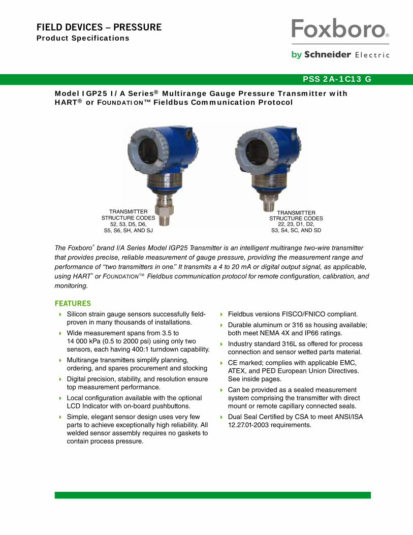
Model IGP25 I/A Series® Multirange Gauge Pressure Transmitter with HART® or FOUNDATION™ Fieldbus Communication Protocol
The Foxboro® brand I/A Series Model IGP25 Transmitter is an intelligent multirange two-wire transmitter that provides precise, reliable measurement of gauge pressure, providing the measurement range and performance of “two transmitters in one.” It transmits a 4 to 20 mA or digital output signal, as applicable, using HART® or FOUNDATION™ Fieldbus communication protocol for remote configuration, calibration, and monitoring.
FEATURES
Silicon strain gauge sensors successfully field-proven in many thousands of installations.
Wide measurement spans from 3.5 to 14 000 kPa (0.5 to 2000 psi) using only two sensors, each having 400:1 turndown capability.
Multirange transmitters simplify planning, ordering, and spares procurement and stocking
Digital precision, stability, and resolution ensure top measurement performance.
Local configuration available with the optional LCD Indicator with on-board pushbuttons.
Simple, elegant sensor design uses very few parts to achieve exceptionally high reliability. All welded sensor assembly requires no gaskets to contain process pressure.
Fieldbus versions FISCO/FNICO compliant.
Durable aluminum or 316 ss housing available; both meet NEMA 4X and IP66 ratings.
Industry standard 316L ss offered for process connection and sensor wetted parts material.
CE marked; complies with applicable EMC, ATEX, and PED European Union Directives. See inside pages.
Can be provided as a sealed measurement system comprising the transmitter with direct mount or remote capillary connected seals.
Dual Seal Certified by CSA to meet ANSI/ISA 12.27.01-2003 requirements.
TRANSMITTERSTRUCTURE CODES
22, 23, D1, D2,S3, S4, SC, AND SD
TRANSMITTERSTRUCTURE CODES
52, 53, D5, D6,S5, S6, SH, AND SJ

PSS 2A-1C13 GPage 2
Multi-marking is available for HART electronic versions for FM, CSA, and ATEX intrinsically safe installations. The user determines and permanently marks on the data plate the certification to be applied.
Designed for hazardous area installations. Versions available to meet Agency flameproof and zone requirements.
Optional mounting bracket sets allow pipe or surface mounting. Also many other options.
Standard 5-year warranty; 17-year optional.
I/A Series PRESSURE TRANSMITTER FAMILY
The I/A Series Electronic Pressure Transmitters are a complete family of d/p Cell®, gauge, absolute, multirange, multivariable, and premium performance transmitters, as well as transmitters with remote or direct mount seals, all using field-proven silicon strain gauge sensors and common topworks.
MULTIRANGE FUNCTIONALITY
The turndown ratio for span adjustment is 400:1. This means that the IGP25 transmitter with its 1400 kPa (200 psi) URL sensor can be set to provide a 4 to 20 mA output for any range between 0 to 3.5 and 0 to 1400 kPa (0 to 5 and 0 to 200 psi). Similarly, the IGP25 transmitter with its 14 MPa (2000 psi) URL sensor covers any range between 0 to 0.035 and 0 to 14 MPa (0 to 5 and 0 to 2000 psi). This means that each sensor covers the ranges normally requiring two separate transmitters.
TRUE MULTIRANGE CAPABILITY
Excellent performance is maintained over a very wide turndown range. The transmitter provides not only the functionality of two transmitters in one, but also provides performance that could previously be attained only by selecting one of several different sensors.
MULTIRANGE PERFORMANCE
Accuracy of ±0.050% of span is maintained for a span adjustment turndown range of 80:1, and does not exceed ±0.075% of span until a full 120:1 turndown is reached. Most competitive transmitters have an error greater than ±0.075% of span when turndowns exceed 10: to 20:1.
The IGP25 can be considered a true multirange transmitter because its performance is maintained over a very wide turndown range, meaning that it performs as well as, or better than, two separate transmitters designed to cover the same turndown range.
DIGITAL AND 4 TO 20 mA OUTPUT VERSIONS
The IGP25 is offered with HART or FOUNDATION Fieldbus communication protocols. See paragraphs that follow.
Digital HART and 4 to 20 mA dc
(Version -T Electronics)
4 to 20 mA with HART communications. Allows direct analog connection to common receivers while still providing full Intelligent Transmitter Digital Communications using a PC-based Configurator, HART Communicator, or optional LCD Indicator with on-board pushbuttons for local configuration and calibration.
4 to 20 mA dc (Configurable) (Version -D
Electronics)
Allows direct analog connection to common receivers while still providing full Intelligent Transmitter Digital Communications with a PC-based Configurator, applicable I/A Series system FBMs, or optional LCD Indicator with on-board pushbuttons for configuration and calibration.

PSS 2A-1C13 GPage 3
Digital FOUNDATION Fieldbus (Version -F
Electronics)
This all digital, serial, two-way communication system interconnects field devices, such as transmitters, actuators, and controllers. It is a Local Area Network (LAN) with built-in capability to distribute control application across the network. Fieldbus technology consists of a Physical Layer, a Communication Stack, and User Application Blocks. The Communication Stack includes an LAS (Link Access Scheduler), and the User Application Blocks include AI (analog input) and PID (proportional, integral, derivative) function blocks. Interoperability of fieldbus devices is achieved using device addresses (IDs) and DDs.
EXCEPTIONAL VALUE
Small size, light weight, direct mounting, standard materials, and wide measurement capability with high performance make this an exceptionally cost effective solution for process pressure measurement.
DIRECT PROCESS MOUNTING
Because of their light weight and external threaded connection, these transmitters can be installed directly on process piping without mounting brackets. However, for unique requirements, optional bracket sets are offered and connection can be made to the standard 1/4 NPT internal thread.
EASE OF INSTALLATION
Rotatable Topworks allows transmitter installation in tight places, allows indicator to be positioned in preferred direction, and eases field retrofit.
Two Conduit Entrances offer a choice of entry positions for ease of installation and self-draining of condensation regardless of mounting position and topworks rotation.
Wiring Guides and Terminations provide ease of wire entry, plenty of space to work and store excess wire, and large, rugged screw terminals for easy wire termination.
316L SS PROCESS WETTED PARTS
With process connection and sensor diaphragm available in industry standard 316L ss, this transmitter is an excellent choice for the vast majority of process pressure measurements.
FISCO/FNICO COMPLIANT
FOUNDATION Fieldbus version certified by ATEX, CSA, FM, and IECEx for FISCO field device intrinsically safe, and FNICO field device protection n installations. Also certified for intrinsically safe and nonsparking user entity parameters.
COMPLIANCE WITH EUROPEAN UNION DIRECTIVES
Complies with Electromagnetic Compatibility Requirements of European EMC Directive 2004/108/EC by conforming to the following EN and IEC Standards: EN 61326-1, and IEC 61000-4-2 through 61000-4-6.
Complies with NAMUR NE 21 Interference Immunity Requirement (EMC).
Analog output complies with NAMUR NE 43 overrange and underrange annunciations.
Complies with all Applicable European Union Directives (“CE” Logo marked on product).
HAZARDOUS AREA INSTALLATIONS
Certified for a wide variety of hazardous area requirements. See Figure for standard and flameproof versions.
Figure 1. IGP25 Transmitters(Flameproof Version Shown on Left)

PSS 2A-1C13 GPage 4 PRESSURE SEALS
OPTIONAL LCD DIGITAL INDICATOR
A two-line digital indicator with on-board pushbuttons is available to display the measurement with a choice of units. The pushbuttons allow zero and span adjustments, as well as local configuration, without the need for a hand-held or PC-based configurator.
SANITARY AND PULP AND PAPER VERSIONS
These transmitters are also available with integral process connections for use in sanitary, and also pulp and paper installations. See PSS 2A-1C13 M and PSS 2A-1C13 N, respectively.
PRESSURE SEALS
Pressure seals are used with the IGP25 when it is necessary to keep the transmitter isolated from the process. A sealed system is used for a process fluid that may be corrosive, viscous, subject to temperature extremes, toxic, sanitary, or tend to collect and solidify.
Figure 1 lists the various seals that can be used with these transmitters. To order a transmitter with seals, both a Transmitter Model Number and Seal Model Number are required. Refer to PSS 2A-1Z11 A for a complete listing of pressure seal models and specifications.
Figure 2. Typical IGP25 Transmitter Configurations with Seals

PRESSURE SEALSPSS 2A-1C13 G
Page 5
Table 1. Pressure Seals Used with IGP25 Transmitters
Direct Connect Pressure Seal Assemblies
Seal Model Seal Description Process Connections
PSFAD Flanged, Direct Connect, Recessed Diaphragm ANSI CLass 150, 300, 600, 1500 flanges
PSFFD Flanged, Direct Connect, Flush Diaphragm ANSI Class 150, 300, 600 and PN 10/40
PSTAD Threaded, Direct Connect, Recessed Diaphragm 1/4, 1/2, 3/4, 1, or 1 1/2 NPT internal thread
PSISD In-Line Saddle Weld, Direct Connect, Recessed Diaphragm
Lower housing of seal is in-line saddle welded nominal 3- or 4-inch pipe
Remote Mount Pressure Seal Assemblies
PSFPS Flanged, Remote Mount, Flush Diaphragm ANSI Class 150/300/600 flanges and BS/DIN PN 10/40 flanges
PSFES Flanged, Remote Mount, Extended Diaphragm ANSI Class 150/300/600 flanges andBS/DIN PN 10/40, 25/40 flanges
PSFFR Flanged, Remote Mount, Flush Diaphragm ANSI Class 150, 300, 600 flanges and DIN/BS PN 10/40
PSFAR Flanged, Remote Mount, Recessed Diaphragm ANSI Class 150/300/600/1500 flanges
PSTAR Threaded, Remote Mount, Recessed Diaphragm 1/4, 1/2, 3/4, 1, or 1 1/2 NPT internal thread
PSISR In-Line Saddle Weld, Remote Mount, Recessed Diaphragm
Lower housing of seal in-line saddle welded to nominal 3- or 4-inch pipe
PSSCR Sanitary, Remote Mount, Flush Diaphragm Process connection secured with a Tri-Clamp to a 2-, 3-, or 4-inch pipe
PSSSR Sanitary, Remote Mount, Extended Diaphragm Tank Spud Seal; 2- or 4-in Tri-Clamp;2-, 6-, or 9-inch extension

PSS 2A-1C13 GPage 6 FUNCTIONAL SPECIFICATIONS
FUNCTIONAL SPECIFICATIONS
Output Signal and Configuration
HART Protocol
4 to 20 mA, with digital HART communications. For multidrop applications, the mA signal is fixed at 4 mA to provide power to the device. Configurable using HART communicator, PC-based Configurator, or optional LCD Indicator.
FOUNDATION Fieldbus Protocol
FOUNDATION Fieldbus digital, serial, two-way communication system that runs at 31.25 kbits/s. The digital output signal is superimposed on the dc power signal on the bus, and controlled by a strict cycle schedule and protocol. Configurable using Host Computer (I/A Series system or a PC) having a Fieldbus interface PWA, or optional LCD Indicator.
Electronics and Sensor Temperatures
Readable from I/A Series system, HART Communicator, PC-based Configurator, or Fieldbus Host System. Measurement is transmitter temperature at the sensor and the electronics module, not necessarily process temperature.
Adjustable Damping
The transmitter response time is normally 0.75 s, or the electronically adjustable setting of 0.00 (none), 0.25, 0.50, 1, 2, 4, 8, 16, or 32 seconds, whichever is greater, for a 90% recovery from an 80% input step as defined in ANSI/ISA S51.1. With Fieldbus, damping can be set in both the transducer and AI (Analog Input) function blocks.
Field Wiring Reversal
No transmitter damage.
Zero and Span Adjustments
Zero and span adjustments can be initiated from the I/A Series Workstation (with applicable FBMs), HART Communicator, PC-based Configurator, or optional LCD Indicator with on-board pushbuttons.
Zeroing for Nonzero-Based Ranges
Dual Function Zeroing is provided to allow zeroing with the transmitter open to atmosphere, even when there is a nonzero-based range. This greatly simplifies position effect zeroing on many pressure and level applications. It even applies to the LCD Indicator and External Zero Adjustment options.
Span and Range Limits
Span LimitCode Span Limits Range Limits
D 0.0035 and 1.4 0.5 and 200 0.035 and 14 0 and 1.4 0 and 200 0 and 14
E 0.035 and 14 5 and 2000 0.35 and 140 0 and 14 0 and 2000 0 and 140
Maximum Overrange and Proof Pressure Ratings
Span LimitCode
Maximum Overrange Pressure Rating (a)
a. Maximum overrange pressure is the maximum pressure that may be applied without causing damage to the transmitter.
Proof Pressure Rating (b)
b. Proof pressure ratings meet ANSI/ISA Standard S82.03-1988. Unit may become nonfunctional after application of proof pressure.
MPa psi bar MPa psi bar
D 2.1 300 21 5.6 710 56
E 21 3000 210 56 7100 560

FUNCTIONAL SPECIFICATIONSPSS 2A-1C13 G
Page 7
Suppressed Zero
Suppressed zero ranges are acceptable as long as the Span and Range Limits are not exceeded.
Current Outputs for Overrange, Fail, and Offline
Conditions - HART Only
Supply Voltage
HART 4 to 20 mA OUTPUT (Figure 3)
Minimum supply voltage of 11.5 V dc can be reduced to 11 V dc by using a plug-in jumper across the test receptacles in the field wiring compartment terminal block. An optional plug-in shorting bar is offered for this purpose.
4 to 20 mA (Figure 3)
Nominal minimum supply voltage is 11.5 V dc. This value can be reduced to 11 V dc by using a plug-in jumper across the test receptacles in the field wiring compartment terminal block. An optional plug-in shorting bar is offered for this purpose.
FOUNDATION Fieldbus Digital Output
9 to 32 V dc, by a specific fieldbus power source connected to the bus. For intrinsically safe (I.S.) applications, the supply voltage allowed can vary depending on the rating of the I.S. barrier.
Figure 3. 4 to 20 mA Output,Supply Voltage vs. Output Load
Write Protect Jumper
Can be positioned to lock out all configurators from making transmitter database changes. This makes transmitter suitable for Safety Shutdown System Applications that require this feature.
Configuration and Calibration Data, and
Electronics Upgradeability
All factory characterization data, and user configuration and calibration data are stored in the sensor. This means that the electronics module can be replaced or changed from one type to another. A module may be replaced without the need for reconfiguration or recalibration. Although module replacement can affect accuracy up to 0.20% of span, this error can be removed by an mA trim without application of pressure.
Changing module types may require reconfiguration and recalibration, as well as a different terminal block, if applicable, but all factory characterization data is retained.
Parameter HART
OFFLINE User configurable between 4 and 20 mA
SENSOR FAILURE
User configurable to Fail LO or Fail HI
FAIL LO 3.60 mA
UNDERRANGE 3.80 mA
OVERRANGE 20.50 mA
FAIL HI 21.00 mA
1500
1000
500
0
OU
TP
UT
LO
AD
, Ω
TYPICAL SUPPLYVOLTAGE ANDLOAD LIMITS
243032
250 & 594250 & 880250 & 975
1450
OPERATINGAREA
0 10 20 30 40 5011.5 42
SUPPLY VOLTAGE, V dc
V dc LOAD Ω
SEE NOTE BELOW
NOTEThe transmitter will function with an output load lessthan 250 Ωprovided that a HART Communicator orPC-based Configurator is not connected to it. Use ofa HART Communicator or PC-based Configurator requires 250 Ω minimum load.
250
SEENOTEBELOW

PSS 2A-1C13 GPage 8 FUNCTIONAL SPECIFICATIONS
4 to 20 mA Analog Mode
Output is updated a minimum of 30/second. A minimum loop load of 250 ohms is required. See Table 2.
HART Communications
HART 4 to 20 mA Analog Mode
Analog output signal is updated 30 times per second. A minimum loop load of 250 ohms is required. See Table 2.
HART Multidrop Mode (Fixed Current)
This Mode supports communications with up to 15 transmitters on a single pair of signal/power wires. The output signal is updated 4 times/second. A minimum loop load of 250 ohms is required. See Table 2.
FOUNDATION Fieldbus Communications
This serial, two-way communication system runs at 31.25 kbits/s. Digital output signal is superimposed on the dc power signal on the bus, and controlled by a strict cycle schedule and protocol. Supply voltage, 9 to 32 V dc, is by a specific Fieldbus power source. Current consumption is 19.5 mA. The maximum number of devices on a non-intrinsically safe bus is 32. For intrinsically safe bus systems, the maximum number is 5. Also see Table 2.
Configuration Capability
Calibrated Range
Input range within Span and Range Limits Pressure EGU (see Table 3)
Output Measurement #1 — Digital Primary
Variable and 4 to 20 mA (HART Only)
Mode: Linear Units: Same as calibrated range
Output Measurement #2 — Digital Secondary
Variable
Mode: Linear Units: A common pressure EGU, or a
custom EGU Measurements #1 and #2: These
measurements may be swapped
NOTEMany parameters can be configured and/or displayed such as electronic damping, failsafe direction, transmitter location, calibration, tag data, etc. See applicable configuration instructions for details.
Table 2. Communication Parameters - HART and FOUNDATION Fieldbus
Parameter
HART Fieldbus
Analog Mode Multidrop Mode Digital
Remote Configurator HART Communicator or PC-based Configurator I/A Series System, PC or Fieldbus Host
Communication Rate 1200 baud 1200 baud 31.25 kbits/s
Communication Distance 3050 m (10,000 ft) 1525 m (5000 ft) 1900 m (6235 ft) (a)
a. The total bus length including all spurs. Maximum spur length is 120 m (395 ft). For hybrid installations, the maximum IS spur length is dependent on the field barrier used. For intrinsically safe bus installations, maximum spur length is 30 m (98 ft).

FUNCTIONAL SPECIFICATIONSPSS 2A-1C13 G
Page 9
Optional External Zero Adjustment
An external pushbutton mechanism is isolated from the electronics compartment and magnetically activates an internal reed switch through the housing. This eliminates a potential leak path for moisture or contaminants to get into the electronics compartment. This external zero adjustment can be disabled by a configuration selection.
Optional LCD Indicator
Indicator provides:
Two Lines; five numeric characters on top line (four when a minus sign is needed) and seven alphanumeric characters on bottom line.
Measurement Readout; value on top line and units label on bottom line.
Configuration and Calibration Prompts.
Two pushbuttons provide for:
Configuration Functions. Calibration Functions.
Figure 4. LCD Indicator with Pushbuttons
Optional Custom Configuration (Option -C2)
For the transmitter to be custom configured by the factory, the user must fill out a data form. If this option is not selected, a standard default configuration will be provided; for example:
Table 3. Allowable Pressure Units for Calibrated Range
inH2OftH2OmmH2OcmH2O (a)
a. Available with Electronics Version -D only.
inHgmmHgcmHg (a)dy/cm2(a)
PakPaMPatorr
mbarbarg/cm2
kg/cm2
psiatm
Parameter
Standard (Default)
ConfigurationExample of Option -C2
Measurement 1 Linear Linear
Device Name DevNam FT103A
External Zero Enabled Disabled
EGU % inH2O
Damping None 0.5 s
TOPWORKSWITH COVERREMOVED
LCDINDICATOR
"ENTER"PUSHBUTTON
"NEXT"PUSHBUTTON
NEXT ENTER
OPTIONALEXTERNALZEROPUSHBUTTON

PSS 2A-1C13 GPage 10 FUNCTIONAL SPECIFICATIONS
Typical Installation Topologies
Refer to Figures 5 through 8 for typical installation topologies.
Figure 5. HART 4 to 20 mA Topology
Figure 6. Fieldbus Miscellaneous Topologies
Figure 7. HART Multidrop Topology
Figure 8. Fieldbus with Mixed Topologies
INDICATOR
HART COMMUNICATOR (OR PC-BASED CONFIGURATOR) MAY BE CONNECTED AT ANY POINT IN THE LOOP SUBJECT TO THE 250 ΩREQUIREMENT SHOWN ABOVE.
CONTROLLER OR RECORDER
+
+
+
+
250 Ω MINIMUM BETWEEN POWERSUPPLY AND COMMUNICATOR
POWERSUPPLY
FIELDBUSINTERFACEELECTRONICS
JUNCTION BOX
BUS WITH SPURS DAISY CHAIN TREE
HOSTCOMPUTER
NOTETERMINATORS AND POWER
SUPPLY NOT SHOWN
HARTCOMPATIBLE
MODEM
GAUGEPRESSXMTR
POWERSUPPLY
d/p CellXMTR
TEMP.XMTR
250 MIN.
HOST COMPUTER
FIELDBUSINTERFACEELECTRONICS
TERMINATE ATJUNCTION BOX
BUS WITH SPURS DAISY CHAIN TREE
HOSTCOMPUTER
NOTETERMINATORS AND POWER
SUPPLY NOT SHOWN.

OPERATING, STORAGE, AND TRANSPORTATION CONDITIONS
PSS 2A-1C13 GPage 11
OPERATING, STORAGE, AND TRANSPORTATION CONDITIONS
Influence
Reference OperatingConditions
Normal Operating Conditions (a)
a. Normal Operating Conditions and Operative Limits are defined per ANSI/ISA 51.1-1979 (R1993).
Operative Limits (a)
Storage and Transportation/
Limits
Process Connection Temp.w/Silicone Fill Fluid
w/Fluorinert Fill Fluid
24 ± 2°C(75 ± 3°F)
24 ± 2°C(75 ± 3°F)
-29 to + 82°C(-20 to +180°F)-29 to + 82°C
(-20 to +180°F)
-46 and +121°C (b)(-50 and +250°F) (b)-29 and +121°C
(-20 and +250°F)
b. Selection of Option -J extends the low temperature operative limit of transmitters with silicone filled sensors down to -50°C (-58°F). Performance is not assured below -29°C. Sensor damage may occur if process is frozen.
Not Applicable
Not Applicable
Electronics Temperature (b)
with LCD Indicator (c)
c. The optional LCD will not be damaged at any temperature within the “Storage and Transportation Limits”; however, updates will be slowed and readability decreased at temperatures outside the “Normal Operating Conditions”.
24 ± 2°C(75 ± 3°F) 24 ± 2°C
(75 ± 3°F)
-29 to + 82°C (d)(-20 to +180°F) (d)-20 to + 82°C (d)
(-4 to +180°F) (d)
d. Refer to the Electrical Safety Specifications section for a restriction in ambient temperature with certain electrical certifications.
-40 and +85°C (d)(-40 and +185°F) (d)-29 and +85°C (d)
(-20 and +185°F) (d)
-54 and +85°C(-65 and +185°F)-54 and +85°C
(-65 and +185°F)
Relative Humidity (e)
e. With topworks cover on and conduit entrances sealed. Also noncondensing during transportation and storage.
50 ±10% 0 to 100% 0 and 100% 0 and 100% (e)Noncondensing
Supply Voltage – mAOutput (HART)
30 ±0.5 V dc 11.5 to 42 V dc (f)
f. 11.5 V dc can be reduced to 11 V dc by using the optional plug-in shorting bar. See Physical Specifications section.
11.5 and 42 V dc (f) Not Applicable
Output Load – mA Output(HART)
650 Ω(see Figure 4)
0 to 1450 Ω (g)
g. With HART, 250 Ω minimum load required for proper communication.
0 and 1450 Ω (g) Not Applicable
Supply VoltageFOUNDATION Fieldbus
30 ±0.5 V dc 9 to 32 V dc (h)
h. Power supplied by a specific Fieldbus power supply.
9 and 32 V dc (h) Not Applicable
Vibration 1 m/s2
(0.1 “g”)6.3 mm (0.25 in) Double Amplitude:
from 5 to 15 Hz with Aluminum Housingfrom 5 to 9 Hz with 316 ss Housing
11 m/s2
(1.1 “g”)from 2.5 to 5 Hz
(in Shipping Package)0 to 30 m/s2 (0 to 3 “g”) from 15 to 500 Hzwith Aluminum Housing;
0 to 10 m/s2 (0 to 1 “g”) from 9 to 500 Hzwith 316 ss Housing
Mounting Position Upright or Horizontal
Upright or Horizontal No Limit Not Applicable

PSS 2A-1C13 GPage 12 PERFORMANCE SPECIFICATIONS
PERFORMANCE SPECIFICATIONS
Zero-Based Calibrations; 316L ss Diaphragm with Silicone Fluid; Under Reference Operating Conditions unless otherwise Specified; URL = Upper Range Limit, and Span = Calibrated Span.
Accuracy (Includes Linearity, Hysteresis, and
Repeatability)
Stability
Long term drift is ±0.15% of URL for 10 years (reference conditions).
Calibration Frequency
The calibration frequency is five years. The five years is derived using the values of allowable error (% span), TPE (% span), performance margin (% span), and stability (% span/month); where:
Power-Up Time
Less than 5 seconds for output to reach first valid measurement.
RFI Effect
The output error is less than 0.1% of span for radio frequencies in the range of 27 to 1000 MHz and field intensity of 30 V/m when the transmitter is properly installed with shielded cable in conduit and earthing (grounding), and housing covers are in place. (Per IEC Std. 61000-4-3.)
Supply Voltage Effect
The output changes less than 0.005% of span for each 1 V change within the specified supply voltage requirements.
Position Effect
The transmitter may be mounted in any position. Any zero effect caused by the mounting position can be eliminated by rezeroing. There is no span effect.
Ambient Temperature Effect
Total effect for a 28°C (50°F) change within Normal Operating Condition limits is:
±(0.03% URL + 0.06% Span)
NOTEFor additional ambient temperature effect when pressure seals are used, see PSS 2A-1Z11 A.
Vibration Effect
Total effect is ±0.2% of URL per “g” for vibrations in the frequency range of 5 to 500 Hz; with double amplitudes of 6.3 mm (0.25 in) in the range of 5 to 15 Hz, or accelerations of 3 “g” in the range of 15 to 500 Hz, whichever is smaller, for transmitters with aluminum housings; and with double amplitudes of 6.3 mm (0.25 in) in the range of 5 to 9 Hz, or accelerations of 1 “g” in the range of 9 to 500 Hz, whichever is smaller, for transmitters with 316 ss housings.
Switching and Indirect Lightning Transients
The transmitter can withstand a transient surge up to 2000 V common mode or 1000 V normal mode without permanent damage. The output shift is less than 1.0%. (Per ANSI/IEEE C62.41-1980 and IEC Std. 61000-4-5.)
Accuracy, % of Span (a)
a. Applies to HART 4 to 20 mA and FOUNDATION Fieldbus.
For Spans ≥1.25% URL
For Spans <1.25% URL
±0.050% ±[0.000625 (URL/Span)]%
Calibration Frequency Performance MarginStability
------------------------------------------------------ Months= =

PHYSICAL SPECIFICATIONSPSS 2A-1C13 G
Page 13
PHYSICAL SPECIFICATIONS
Environmental Protection
The enclosure has the dusttight and weatherproof rating of IP66 as defined by IEC 60529, and provides the environmental and corrosion resistant protection rating of NEMA 4X.
Process Wetted Materials (High Pressure Side)
Industry Standard 316L ss for process connection and sensor diaphragm
Reference Side Materials (Atmospheric Side)
Silicon, Pyrex, RTV, and 316 ss.
Sensor Fill Fluids
Silicone Oil or Inert (FC-43)
Electronics Housing and Housing Covers
Housing has two compartments to separate the electronics from the field connections. The housing and covers are made from low copper (0.6% maximum) die-cast aluminum alloy with an epoxy finish, or from 316 ss. Buna-N O-ring seals are used to seal the threaded housing covers, housing neck, and terminal block.
Electronics Module
Printed wiring assemblies are conformally coated for moisture and dust protection.
Mounting Position
The transmitter may be mounted in any orientation.
Electrical Connections
Field wires enter through 1/2 NPT, PG 13.5, or M20 threaded entrances on either side of the electronics housing. Wires terminate under screw terminals and washers on terminal block in the field terminal compartment (Figure ). Unused entrance is plugged to insure moisture and RFI/EMI protection.
Approximate Mass
1.5 kg (3.3 lb) – with Aluminum Housing Add 1.1 kg (2.4 lb) – with 316 ss Housing Add 0.2 kg (0.4 lb) – with LCD Indicator Option With Pressure Seals – see PSS 2A-1Z11 A.
Dimensions
See “Dimensions – Nominal”.
Figure 9. Field Terminals Compartment for HART and Fieldbus
A
B
EARTH (GROUND)TERMINAL SCREW,0.164-32
POLARITYINDEPENDENTTERMINALS:0.164-32SCREWS
TERMINAL BLOCKLOCATED IN FIELDTERMINAL SIDE OFTRANSMITTER
-
EARTH (GROUND)TERMINAL SCREW,0.164-32
(+) AND (-) POWER TERMINAL SCREWS, 0.164-32
RECEPTACLES (3)FOR STANDARDBANANA PLUGS
HHT
CAL+
TERMINAL BLOCKLOCATED IN FIELDTERMINAL SIDE OFTRANSMITTER
USED TO CHECK TRANSMITTER 4 TO 20 mA OUTPUT
OPTIONAL SHORTING BAR (SB-11) REDUCESMINIMUM VOLTAGEFROM 11.5 TO 11 V dc
-T HART VERSIONFOR HART COMMUNICATOR ORPC-BASED CONFIGURATOR PLUGS
-T HART TRANSMITTER VERSION
-F FOUNDATION Fieldbus TRANSMITTER VERSION
+
SURGEPROTECTIONJUMPER

PSS 2A-1C13 GPage 14 ELECTRICAL SAFETY SEPCIFICATIONS
ELECTRICAL SAFETY SEPCIFICATIONS
The transmitter has been designed to meet the Electrical Safety Specifications listed in the tables that follow. Contact Global Customer Support for information or status of testing laboratory approvals or certifications.
With Electrical Safety Design Codes M and P, the user must permanently mark (check off on rectangular box on data plate) one type of protection only (ia and ib, d, or n). Do not change this mark once it has been applied.
When selecting Safety Design Code W (for HART only), the user must permanently mark (check off in rectangular block on data plate) intrinsically safe certifications for ATEX, CSA, or FM, as applicable. Do not change this mark once it has been applied.
Electronic Version -T, HART
Testing Laboratory, Types of Protection, and Area Classification Application Conditions
Elec. Safety Design Code
ATEX intrinsically safe; II 1 GD, EEx ia IIC, Zone 0, or II 1/2 GD EEx ib IIC, Zone 0/Zone 1.
Temperature Class T4; Ta = -40 to +80°CTemperature Class T5; Ta = -40 to +40°CTemperature Class T6; Ta = -40 to +40°C
E
ATEX flameproof; II 2 GD, EEx d IIC, Zone 1. Temperature Class T6, 85°C; Ta = -40 to +80°C
D
ATEX protection n; II 3 GD, EEx nL IIC, Zone 2. Temperature Class T4; Ta = -40 to +80°CTemperature Class T5; Ta = -40 to +70°CTemperature Class T6; Ta = -40 to +40°C
N
ATEX multiple certifications, ia & ib, and n. Refer to Codes E and N for details.
Applies to Codes E and N, but not to Code D (Note 2)
M
ATEX multiple certifications, ia & ib, d, and n. Refer to Codes D, E and N for details.
Applies to Codes D, E, and N (Note 2) P
CSA intrinsically safe for Class I, Div. 1, Groups A, B, C, and D, Class II, Div. 1, Groups E, F, and G, and Class III, Div. 1.
Connect per MI 020-427. Temperature Class T6 at 40°C, and T3C at 85°C maximum ambient
C
CSA zone certified intrinsically safe Ex ia IIC, and energy limited Ex nA II.
Temperature Class T4 at 40°C, and T3 at 85°C maximum ambient
C
CSA explosionproof for Class I, Div. 1, Groups B, C, and D; dust-ignitionproof for Class II, Div. 1, Groups E, F, and G; and Class III, Div. 1.
Maximum Ambient Temperature 85°C C
CSA for Class I, Div. 2, Groups A, B, C, and D; Class II, Div. 2, Groups F and G; Class III, Div. 2.
Temperature Class T6 at 40°C and T4A at 85°C maximum ambient
C
CSA field device zone certified flameproof Ex d IIC. Also, all certifications of Code C above.
Maximum Ambient Temperature 85°C B
FM intrinsically safe for Class I, Div. 1, Groups A, B, C, and D; Class II, Div. 1, Groups E, F, and G; and Class III, Div. 1.
Connect per MI 020-427. Temperature Class T4A at 40°C and T4 at 85°C maximum ambient
F
FM zone certified intrinsically safe AEx ia IIC. Temperature Class T4 at 85°C maximum ambient
F
FM explosionproof for Class I, Div. 1, Groups B, C, and D; dust-ignitionproof for Class II, Div. 1, Groups E, F, and G; and Class III, Div. 1.
Temperature Class T6 at 80°C and T5 at 85°C maximum ambient
F
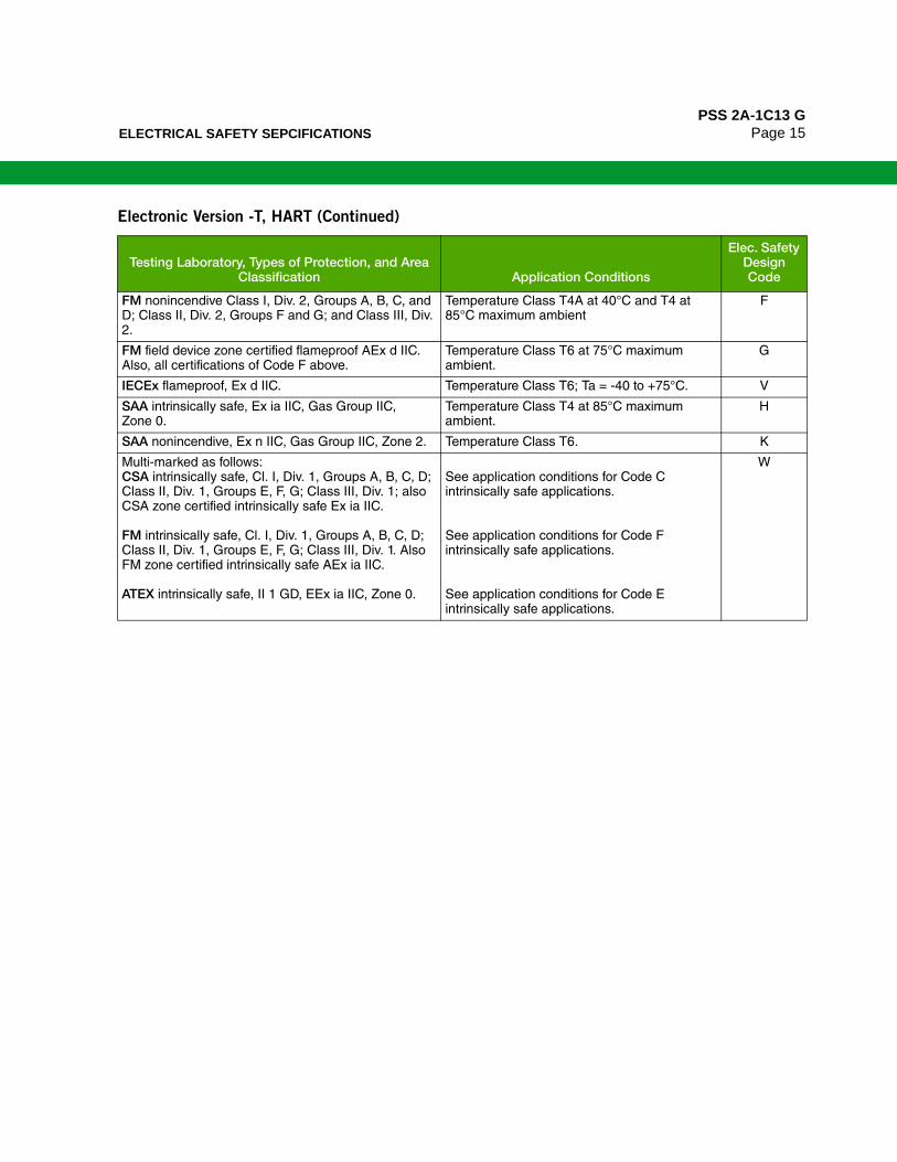
ELECTRICAL SAFETY SEPCIFICATIONSPSS 2A-1C13 G
Page 15
FM nonincendive Class I, Div. 2, Groups A, B, C, and D; Class II, Div. 2, Groups F and G; and Class III, Div. 2.
Temperature Class T4A at 40°C and T4 at 85°C maximum ambient
F
FM field device zone certified flameproof AEx d IIC. Also, all certifications of Code F above.
Temperature Class T6 at 75°C maximum ambient.
G
IECEx flameproof, Ex d IIC. Temperature Class T6; Ta = -40 to +75°C. V
SAA intrinsically safe, Ex ia IIC, Gas Group IIC, Zone 0.
Temperature Class T4 at 85°C maximum ambient.
H
SAA nonincendive, Ex n IIC, Gas Group IIC, Zone 2. Temperature Class T6. K
Multi-marked as follows:CSA intrinsically safe, Cl. I, Div. 1, Groups A, B, C, D; Class II, Div. 1, Groups E, F, G; Class III, Div. 1; also CSA zone certified intrinsically safe Ex ia IIC.
FM intrinsically safe, Cl. I, Div. 1, Groups A, B, C, D; Class II, Div. 1, Groups E, F, G; Class III, Div. 1. Also FM zone certified intrinsically safe AEx ia IIC.
ATEX intrinsically safe, II 1 GD, EEx ia IIC, Zone 0.
See application conditions for Code C intrinsically safe applications.
See application conditions for Code F intrinsically safe applications.
See application conditions for Code E intrinsically safe applications.
W
Electronic Version -T, HART (Continued)
Testing Laboratory, Types of Protection, and Area Classification Application Conditions
Elec. Safety Design Code
PSS 2A-1C13 GPage 16 ELECTRICAL SAFETY SEPCIFICATIONS
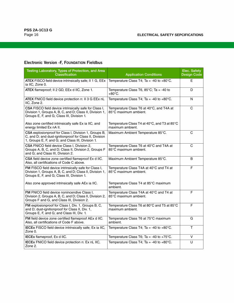
Electronic Version -F, FOUNDATION Fieldbus
Testing Laboratory, Types of Protection, and Area Classification Application Conditions
Elec. Safety Design Code
ATEX FISCO field device intrinsically safe; II 1 G, EEx ia IIC, Zone 0.
Temperature Class T4; Ta = -40 to +80°C. E
ATEX flameproof; II 2 GD, EEx d IIC, Zone 1. Temperature Class T6, 85°C; Ta = -40 to +80°C.
D
ATEX FNICO field device protection n: II 3 G EEx nL IIC, Zone 2.
Temperature Class T4; Ta = -40 to +80°C. N
CSA FISCO field device intrinsically safe for Class I, Division 1, Groups A, B, C, and D; Class II, Division 1, Groups E, F, and G; Class III, Division 1.
Also zone certified intrinsically safe Ex ia IIC, and energy limited Ex nA II.
Temperature Class T6 at 40°C, and T4A at 85°C maximum ambient.
Temperature Class T4 at 40°C, and T3 at 85°C maximum ambient.
C
CSA explosionproof for Class I, Division 1, Groups B, C, and D; and dust-ignitionproof for Class II, Division 1, Groups E, F, and G; and Class III, Division 1.
Maximum Ambient Temperature 85°C. C
CSA FNICO field device Class I, Division 2, Groups A, B, C, and D; Class II, Division 2, Groups F and G; and Class III, Division 2.
Temperature Class T6 at 40°C and T4A at 85°C maximum ambient.
C
CSA field device zone certified flameproof Ex d IIC. Also, all certifications of Code C above.
Maximum Ambient Temperature 85°C. B
FM FISCO field device intrinsically safe for Class I, Division 1, Groups A, B, C, and D; Class II, Division 1, Groups E, F, and G; Class III, Division 1.
Also zone approved intrinsically safe AEx ia IIC.
Temperature Class T4A at 40°C and T4 at 85°C maximum ambient.
Temperature Class T4 at 85°C maximum ambient.
F
FM FNICO field device nonincendive Class I, Division 2, Groups A, B, C, and D; Class II, Division 2, Groups F and G, and Class III, Division 2.
Temperature Class T4A at 40°C and T4 at 85°C maximum ambient.
F
FM explosionproof for Class I, Div. 1, Groups B, C, and D; dust-ignitionproof for Class II, Div. 1, Groups E, F, and G; and Class III, Div. 1.
Temperature Class T6 at 80°C and T5 at 85°C maximum ambient.
F
FM field device zone certified flameproof AEx d IIC. Also, all certifications of Code F above.
Temperature Class T6 at 75°C maximum ambient.
G
IECEx FISCO field device intrinsically safe; Ex ia IIC, Zone 0.
Temperature Class T4; Ta = -40 to +80°C. T
IECEx flameproof, Ex d IIC. Temperature Class T6; Ta = -40 to +75°C. V
IECEx FNICO field device protection n: Ex nL IIC, Zone 2.
Temperature Class T4; Ta = -40 to +80°C. U

MODEL CODEPSS 2A-1C13 G
Page 17
MODEL CODE
Description ModelI/A Series, Multirange, Direct Connected Gauge Pressure Transmitter (a) IGP25
Electronics Versions and Output Signal
Intelligent; Digital HART and 4 to 20 mA dc (Version -T)Intelligent; Digital FOUNDATION Fieldbus (Version -F)
-T-F
Structure Code - Select from one of the following six groups:
1. Transmitter Only (no seals)
Process Connection Sensor Fill Fluid Connection Type316L ss 316L ss Silicone 1/2 NPT External Thread, 1/4 NPT Internal Thread316L ss 316L ss Inert 1/2 NPT External Thread, 1/4 NPT Internal Thread
2223
2. Transmitter Prepared for Foxboro Model Coded Seals (b)
Transmitter Prepared for Foxboro Direct Connect Seal; Silicone Fill in Sensor (c)Transmitter Prepared for Foxboro Direct Connect Seal; Inert Fill in Sensor (c)Transmitter Prepared for Foxboro Remote Mount Seal; Silicone Fill in Sensor (d)Transmitter Prepared for Foxboro Remote Mount Seal; Inert Fill in Sensor (d)
D1D2S3S4
3. Transmitters Prepared for non-Foxboro Seals
Transmitter Prepared for Remote Seal; Silicone Fill in Sensor (e)Transmitter Prepared for Remote Seal; Inert Fill in Sensor (f)
SCSD
4. Flameproof Transmitter Only (no seals)
Process Connection Sensor Fill Fluid Connection Type316L ss 316L ss Silicone 1/2 NPT External Thread, 1/4 NPT Internal Thread316L ss 316L ss Inert 1/2 NPT External Thread, 1/4 NPT Internal Thread
5253
5. Flameproof Transmitter Prepared for Foxboro Model Coded Seals (b)
Flameproof Transmitter Prepared for Direct Connect Seal; Silicone Fill in Sensor (c)Flameproof Transmitter Prepared for Direct Connect Seal; Inert Fill in Sensor (c)Flameproof Transmitter Prepared for Remote Mount Seal; Silicone Fill in Sensor (d)Flameproof Transmitter Prepared for Remote Mount Seal; Inert Fill in Sensor (d)
D5D6S5S6
6. Flameproof Transmitter Prepared for non-Foxboro SealsFlameproof Transmitter Prepared for Remote Seal; Silicone Fill in Sensor (e)Flameproof Transmitter Prepared for Remote Seal; Inert Fill in Sensor (f)
SHSJ
Span Limits
MPa psi bar
0.0035 and 1.4 0.5 and 200 0.035 and 140.035 and 14 5 and 2000 0.35 and 140
DE
Conduit Connection and Housing Material
1/2 NPT Conduit Connection, Aluminum HousingPG 13.5 Conduit Connection, Aluminum Housing (Electrical Safety Codes E, D, M, N, and P only)1/2 NPT Conduit Connection, 316 ss HousingPG 13.5 Conduit Connection, 316 ss Housing (Electrical Safety Codes E, D, M, N, and P only)M20 Conduit Connection, Both Sides, Aluminum Housing (Electrical Safety Codes E, D, M, N, P only)M20 Conduit Connection, Both Sides, 316 ss Housing (Electrical Safety Codes E, D, M, N, P only)
123456
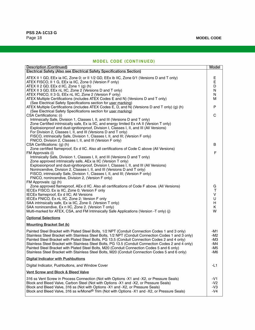
PSS 2A-1C13 GPage 18 MODEL CODE
Electrical Safety (Also see Electrical Safety Specifications Section)
ATEX II 1 GD, EEx ia IIC, Zone 0; or II 1/2 GD, EEx ib IIC, Zone 0/1 (Versions D and T only)ATEX FISCO, II 1 G, EEx ia IIC, Zone 0 (Version F only)ATEX II 2 GD, EEx d IIC, Zone 1 (g) (h)ATEX II 3 GD, EEx nL IIC, Zone 2 (Versions D and T only)ATEX FNICO, II 3 G, EEx nL IIC, Zone 2 (Version F only)ATEX Multiple Certifications (includes ATEX Codes E and N) (Versions D and T only)
(See Electrical Safety Specifications section for user marking)ATEX Multiple Certifications (includes ATEX Codes E, D, and N) (Versions D and T only) (g) (h)
(See Electrical Safety Specifications section for user marking)CSA Certifications: (i)
Intrinsically Safe, Division 1, Classes I, II, and III (Versions D and T only)Zone Certified intrinsically safe, Ex ia IIC, and energy limited Ex nA II (Version T only)Explosionproof and dust-ignitionproof, Division I, Classes I, II, and III (All Versions)For Division 2, Classes I, II, and III (Versions D and T only)FISCO, intrinsically Safe, Division 1, Classes I, II, and III; (Version F only)FNICO, Division 2, Classes I, II, and III (Version F only)
CSA Certifications: (g) (h)Zone certified flameproof, Ex d IIC. Also all certifications of Code C above (All Versions)
FM Approvals (i)Intrinsically Safe, Division 1, Classes I, II, and III (Versions D and T only) Zone approved intrinsically safe, AEx ia IIC (Version T only)Explosionproof and dust-ignitionproof, Division I, Classes I, II, and III (All Versions)Nonincendive, Division 2, Classes I, II, and III (Versions D and T only)FISCO, intrinsically Safe, Division 1, Classes I, II, and III; (Version F only)FNICO, nonincendive, Division 2, (Version F only)
FM Approvals: (g) (h)Zone approved flameproof, AEx d IIC. Also all certifications of Code F above. (All Versions)
IECEx FISCO, Ex ia IIC, Zone 0; Version F onlyIECEx flameproof, Ex d IIC; All Versions IECEx FNICO, Ex nL IIC, Zone 2; Version F onlySAA intrinsically safe, Ex ia IIC, Zone 0. (Version T only)SAA nonincendive, Ex n IIC, Zone 2. (Version T only)Multi-marked for ATEX, CSA, and FM Intrinsically Safe Applications (Version -T only) (j)
EEDNNM
P
C
B
F
G TVUHKW
Optional Selections
Mounting Bracket Set (k)
Painted Steel Bracket with Plated Steel Bolts, 1/2 NPT (Conduit Connection Codes 1 and 3 only)Stainless Steel Bracket with Stainless Steel Bolts, 1/2 NPT (Conduit Connection Codes 1 and 3 only)Painted Steel Bracket with Plated Steel Bolts, PG 13.5 (Conduit Connection Codes 2 and 4 only)Stainless Steel Bracket with Stainless Steel Bolts, PG 13.5 (Conduit Connection Codes 2 and 4 only)Painted Steel Bracket with Plated Steel Bolts, M20 (Conduit Connection Codes 5 and 6 only)Stainless Steel Bracket with Stainless Steel Bolts, M20 (Conduit Connection Codes 5 and 6 only)
-M1-M2-M3-M4-M5-M6
Digital Indicator with Pushbuttons
Digital Indicator, Pushbuttons, and Window Cover -L1
Vent Screw and Block & Bleed Valve
316 ss Vent Screw in Process Connection (Not with Options -X1 and -X2, or Pressure Seals)Block and Bleed Valve, Carbon Steel (Not with Options -X1 and -X2, or Pressure Seals)Block and Bleed Valve, 316 ss (Not with Options -X1 and -X2, or Pressure Seals)Block and Bleed Valve, 316 ss w/Monel® Trim (Not with Options -X1 and -X2, or Pressure Seals)
-V1-V2-V3-V4
MODEL CODE (CONTINUED)
Description (Continued) Model

MODEL CODEPSS 2A-1C13 G
Page 19
Conduit Thread Adapters (Not available with Conduit Connection Codes 5 and 6)
Hawke-Type 1/2 NPT Cable Gland for use with Conduit Connection Codes 1 and 3 only (l)Plastic PG 13.5 Cable Gland for use with Conduit Connection Codes 2 and 4 only (m)M20 Connector for use with Conduit Connection Codes 1 and 3 only (l)Brass PG 13.5 Cable Gland (Trumpet-Shaped); with Conduit Connection Codes 2 and 4 only (m)
-A1-A2-A3-A4
Electronics Housing Features
External Zero AdjustmentCustody Transfer Lock and SealExternal Zero Adjustment and Custody Transfer Lock and Seal
-Z1-Z2-Z3
Custom Factory Configuration
Digital Output (4 to 20 mA default if not selected) (with Electronics Version -D only)Full Factory Configuration (Requires Configuration Form to be filled out)
-C1-C2
Cleaning and Preparation
Unit Degreased - for Silicone Filled Sensors OnlyNot for Oxygen/Chlorine Service, Options -V1 to -V4, or Pressure Seals
Cleaned and Prepared for Oxygen Service - for Inert Filled Sensors OnlyNot with Option -V1 to -V4, or Pressure Seals
-X1
-X2
Instruction Books (Common MI, Brochure, and Full Documentation Set on DVD is
Standard)
Without Instruction Book and DVD - Only “Getting Started” Brochure is supplied
-K1
Miscellaneous Optional Selections
G 1/2 B Manometer Process Connection (Not Available with Option -V1 or Pressure Seals)Low Temperature Operative Limit of Electronics Housing Extended Down to -50°C (-58°F) (n) (o)R 1/2 Process Connection (1/2 NPT to R 1/2 Adapter) (p)Supplemental Customer Tag (Stainless Steel Tag wired onto Transmitter)Seventeen Year Warranty
-G-J-R-T-W
Example: IGP25–T22E3F–M3L1C2JT
a. Refer to PSS 2A-1C13 M and PSS 2A-1C13 N for IGP25 versions for the sanitary, and pulp/paper industries, respectively.
b. Both transmitter and pressure seal Model Numbers are required. Refer to PSS 2A-1Z11 A for pressure seal Model Codes.
c. Direct Connect Seal Models that may be specified are PSTAD, PSFAD, PSFFD, and PSISD.
d. Remote Mount Seal Models that may be specified are PSFPS, PSFES, PSFFR, PSFAR, PSTAR, PSISR, PSSCR, and PSSSR.
e. For transmitters with Silicone fill prepared for remote seal by others, specify Structure Code 22 or 52.
f. For transmitters with Fluorinert fill prepared for remote seal by others, specify Structure Code 23 or 53.
g. Electrical Safety Codes B, D, G, P, and V are only available with flameproof transmitter Structure Codes 52, 53, D5, D6, S5, S6, SH, and SJ.
h. A cover lock is provided as standard with Electrical Safety Codes D, B, G, and P.
i. Electrical Safety Codes C, F, H, A, and K are not available with flameproof transmitter Structure Codes 52, 53, D5, D6, S5, S6, SH, and SJ.
j. For multi-marking details, see Electrical Safety Specifications section.
k. Mounting sets not offered with direct mounted seals, except if a direct mounted PSTAD threaded seal with a 1/4 NPT process connection is used, then a mounting set is recommended.
l. Available with Electrical Safety Codes E, D, M, N, and P only.
m. Available with Electrical Safety Code E only.
n. Not available with Inert fill in sensor or seal.
o. -50°C indicates sensor and electronics ambient temperature capabilities. Performance is not assured below -29°C. Sensor damage may occur if process is frozen.
p. Not available with pressure seals or nickel alloy (equivalent to Hastelloy® C sensors. Hastelloy® is a registered trademark of Haynes International, Inc.).
MODEL CODE (CONTINUED)
Description (Continued) Model

PSS 2A-1C13 GPage 20 SUGGESTED RFQ SPECIFICATIONS
SUGGESTED RFQ SPECIFICATIONS
The manufacturer shall provide direct connected, multirange pressure transmitters featuring HART or FOUNDATION Fieldbus Communication Protocol. They shall provide remote digital communications capability for measuring gauge pressure and transmit a digital or 4 to 20 mA (HART only) output signal for use in a standard two-wire dc supply voltage system. These transmitters shall also be provided (as required) with direct or remote mount pressure seals. The specifications for these transmitters are as follows:
CommunicationProtocol:
HART Digital and/or 4 to 20 mA dc output signalFOUNDATION Fieldbus: Digital output signal
Communications: Remote Communications must not interfere with output.Span Turndown Ratio: 400:1
Accuracy: ±0.050% of calibrated span for spans ≥ 1.25% of URL.Damping: Settable for a range of none to 32 seconds.
RFI Protection: 0.1% error between 27 and 1000 MHz at 30 V/m field intensityProof Pressure: 710 or 7100 psi, depending on sensor selected.
Span Limits: From 0.5 to 2000 psi using only two sensors.Enclosure: 316 ss, or Aluminum enclosure with Epoxy finish
Modular Electronics: Enclosed in a NEMA 4X/IEC IP66 rated housing sealed with O-rings to protect against moisture or other contaminants. Optional LCD Digital Indicator with on-board pushbuttons.
Mounting: Direct to process or bracket mounted to pipe or surface.Process Connection: Direct connected to process piping with 1/2 NPT
or optional R 1/2 or G 1/2 B external threads. Internal 1/4 NPT thread also provided as plumbing connection to process. Process connection can also be prepared for an installed Foxboro direct connect seal or capillary connected seal.
Sensor Materials: Industry standard 316L ss.Electrical Safety: Nonincendive, flameproof, intrinsically safe, or explosionproof agency approvals.
Versions available to meet Agency flameproof and zone requirements. Comply with applicable European Union Directives.
Approximate Mass: Direct Connected Transmitter: 1.5 kg (3.3 lb); does not include seals.With 316 ss Electronics Housing: Add 1.1 kg (2.4 lb)With Optional LCD Indicator: Add 0.2 kg (0.4 lb)
Model Code: Foxboro Model IGP25 Multirange Gauge Pressure Transmitter; with HART or FOUNDATION Fieldbus Communication Protocol; with or without pressure seals; or equivalent
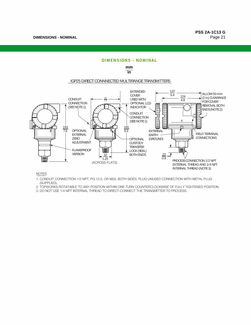
DIMENSIONS - NOMINALPSS 2A-1C13 G
Page 21
DIMENSIONS - NOMINAL
IGP25 DIRECT CONNNECTED MULTIRANGE TRANSMITTERS
CONDUITCONNECTION(SEE NOTE 1)
EXTENDEDCOVERUSED WITH OPTIONAL LCDINDICATOR
ALLOW 50 mm (2 in) CLEARANCEFOR COVER REMOVAL BOTH ENDS (NOTE 2)
FIELD TERMINALCONNECTIONS
CONDUITCONNECTION(SEE NOTE 1)
OPTIONALCUSTODYTRANSFERLOCK (SEAL)BOTH ENDS
FIEL
DTE
RMIN
ALS
EXTERNALEARTH(GROUND)
PROCESS CONNECTION 1/2 NPT EXTERNAL THREAD AND 1/4 NPT INTERNAL THREAD (NOTE 3)
OPTIONALEXTERNALZEROADJUSTMENT
(ACROSS FLATS)
1656.5
321.25
1375.4 124
4.9
230.9
1937.6
963.8
FLAMEPROOFVERSION
NOTES
1. CONDUIT CONNECTION 1/2 NPT, PG 13.5, OR M20, BOTH SIDES: PLUG UNUSED CONNECTION WITH METAL PLUG (SUPPLIED).2. TOPWORKS ROTATABLE TO ANY POSITION WITHIN ONE TURN COUNTERCLOCKWISE OF FULLY TIGHTENED POSITION.3. DO NOT USE 1/4 NPT INTERNAL THREAD TO DIRECT-CONNECT THE TRANSMITTER TO PROCESS.
mmin
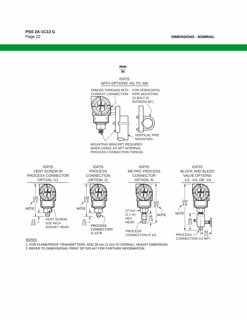
PSS 2A-1C13 GPage 22 DIMENSIONS - NOMINAL
mmin
MOUNTING BRACKET REQUIRED WHEN USING 1/4 NPT INTERNALPROCESS CONNECTION THREAD.
VERTICAL PIPEMOUNTING
SPACER THREADS INTO CONDUIT CONNECTION
FOR HORIZONTALPIPE MOUNTING(U-BOLT IS ROTATED 90°)
IGP25WITH OPTIONS -M1 TO -M6
481.9
2038.0
2449.6
893.5
642.5
27 mm (1.1 in)HEX HEAD
PROCESS CONNECTION R 1/2 PROCESS
CONNECTION 1/2 NPT
1. FOR FLAMEPROOF TRANSMITTERS, ADD 28 mm (1.1in) TO OVERALL HEIGHT DIMENSION.2. REFER TO DIMENSIONAL PRINT DP 020-447 FOR FURTHER INFORMATION.
NOTES
VENT SCREW5/32 INCHSOCKET HEAD
IGP25VENT SCREW IN
PROCESS CONNECTOROPTION -V1
1656.5
230.9
NOTE
IGP25METRIC PROCESS
CONNECTOROPTION -R
NOTE
NOTE
IGP25BLOCK AND BLEED
VALVE OPTIONS-V2, -V3, OR -V4
IGP25PROCESS
CONNECTIONOPTION -G
1686.6
251.0
NOTE
PROCESS CONNECTIONG 1/2 B

NOTESPSS 2A-1C13 G
Page 23
NOTES
PSS 2A-1C13 GPage 24
ORDERING INSTRUCTIONS
OTHER FOXBORO PRODUCTS
1. Model Number(s) as follows:Transmitter only if pressure seals are not selectedBoth transmitter and pressure seal if pressure seal is selected.
See PSS 2A-1Z11 A.
2. Calibrated Pressure Range (using Allowable Pressure Units from the table below).
3. Configuration Data Form when Factory Calibration Option -C2 is specified.
4. Options and Accessories not in Model Code (see PSS 2A-1Z9 E).
5. User Tag Data – Data Plate; 32 characters maximum. For additional tag data, specify Optional Supplemental Tag -T.
6. User Tag Data - Software (Database):HART, -T; 8 characters maximumFieldbus, -F; 32 characters maximum.
The Foxboro product lines offer a broad range of measurement and instrument products, including solutions for pressure, flow, analytical, temperature, positioning, controlling, and recording.
For a list of these offerings, visit our web site at:
www.fielddevices.foxboro.com
inH2O inHg kPa mbar kg/cm2
ftH2O mmHg MPa bar psia
mmH2O Pa torr g/cm2 atm
Invensys Systems, Inc.38 Neponset AvenueFoxboro, MA 02035United States of Americahttp://www.invensys.com
Global Customer SupportInside U.S.: 1-866-746-6477Outside U.S.:1-508-549-2424Website: http://support.ips.invensys.com
Copyright 2001-2015 Invensys Systems, Inc. All rights reserved.
Invensys, Foxboro, d/p Cell, and I/A Series are trademarks of Invensys Limited, its subsidiaries, and affiliates. All other trademarks are the property of their respective owners.
Invensys is now part of Schneider Electric.
1115