field failure analysis in the electronics supply chain · pdf filezvei - field failure...
TRANSCRIPT

Field failure analysis in the
electronics supply chain
Division Electronic Components and Systems

Legal notices Field failure analysis in the electronics supply chain Publisher: ZVEI - Zentralverband Elektrotechnik- und Elektronikindustrie e.V. Electronic Components and Systems Division Lyoner Str. 9 60528 Frankfurt am Main
Telephone: +49 69 6302-276 Fax: +49 69 6302-407 Email: [email protected] www.zvei.org Contact person: Dr.-Ing. Rolf Winter Authors Rainer Eckl Analog Devices GmbH Dietmar Sigmann Atmel Automotive GmbH Rainer Wüstenhagen Automotive Lighting Reutlingen GmbH Mark Widmann Robert Bosch GmbH Gregor Lambertz Delphi Deutschland GmbH Jens Pfeiffer Freescale Halbleiter Deutschland GmbH Mirko Klug Huf Hülsbeck & Fürst GmbH & Co. KG
(from VDA-QMC workgroup) Lothar Doni Inova Semiconductors GmbH Norbert Bauer Murata Elektronik GmbH Stephan Jegl Marquardt GmbH (chairman) Rudolf Geppert NXP Semiconductors Germany GmbH Florian Wieser ST Microelectronics Application GmbH Heinz Seiler Webasto SE Christoph Lack ZF Friedrichshafen AG Revision: 1.1 September 2015 This document can be reproduced in any format or medium, also in the form of extracts, free of charge provided that it is used correctly and not in a misleading context. The ZVEI copyright must be evident and the title of the document must be indicated. A complimentary copy of the document in which ZVEI material is used must be made available. Despite great care being taken in the creation of this brochure, no legal responsibility can be assumed for any errors, omissions or misleading statements within it. This document and additional information can be found on the ZVEI website www.zvei.org/Schadteilanalyse or www.zvei.org under the rubric "Publications".
INTRODUCTION
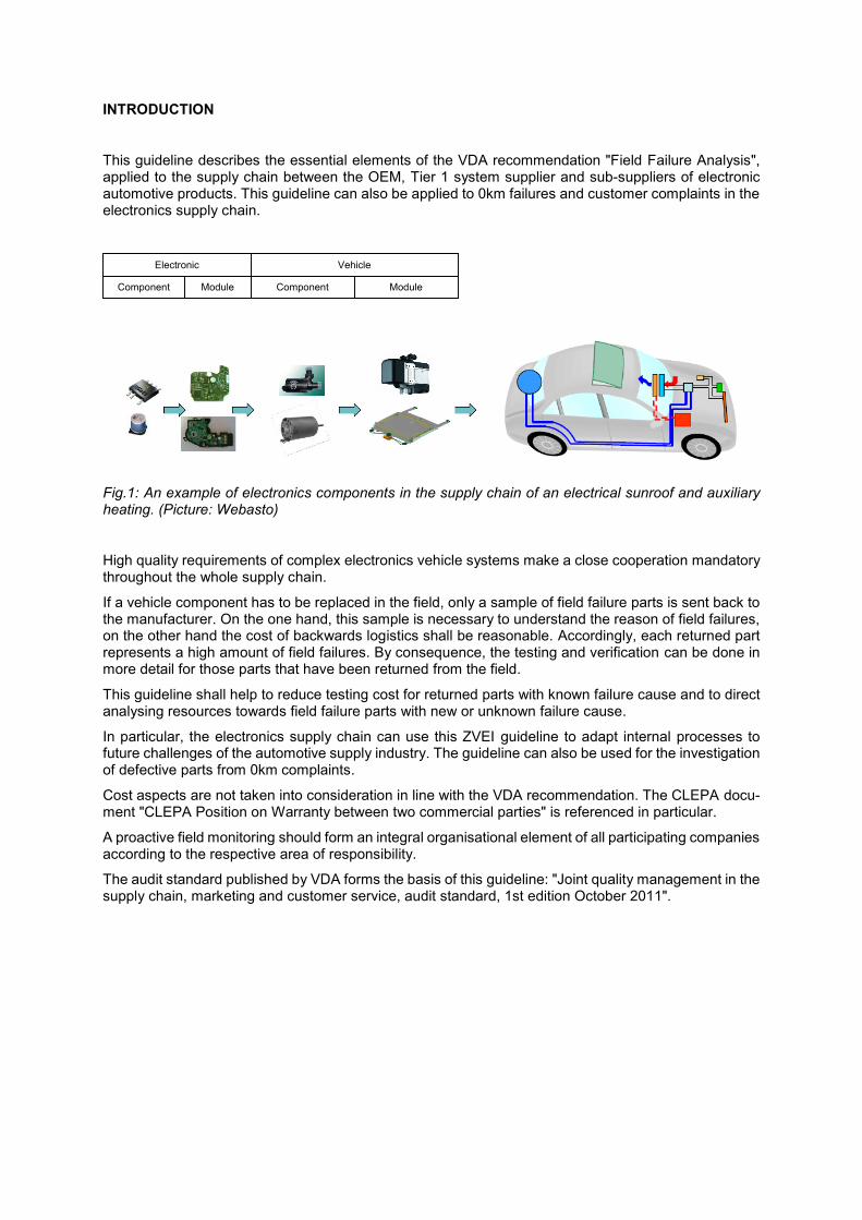
This guideline describes the essential elements of the VDA recommendation "Field Failure Analysis", applied to the supply chain between the OEM, Tier 1 system supplier and sub-suppliers of electronic automotive products. This guideline can also be applied to 0km failures and customer complaints in the electronics supply chain.
Fig.1: An example of electronics components in the supply chain of an electrical sunroof and auxiliary heating. (Picture: Webasto)
High quality requirements of complex electronics vehicle systems make a close cooperation mandatory throughout the whole supply chain.
If a vehicle component has to be replaced in the field, only a sample of field failure parts is sent back to the manufacturer. On the one hand, this sample is necessary to understand the reason of field failures, on the other hand the cost of backwards logistics shall be reasonable. Accordingly, each returned part represents a high amount of field failures. By consequence, the testing and verification can be done in more detail for those parts that have been returned from the field.
This guideline shall help to reduce testing cost for returned parts with known failure cause and to direct analysing resources towards field failure parts with new or unknown failure cause.
In particular, the electronics supply chain can use this ZVEI guideline to adapt internal processes to future challenges of the automotive supply industry. The guideline can also be used for the investigation of defective parts from 0km complaints.
Cost aspects are not taken into consideration in line with the VDA recommendation. The CLEPA docu-ment "CLEPA Position on Warranty between two commercial parties" is referenced in particular.
A proactive field monitoring should form an integral organisational element of all participating companies according to the respective area of responsibility.
The audit standard published by VDA forms the basis of this guideline: "Joint quality management in the supply chain, marketing and customer service, audit standard, 1st edition October 2011".
Component Module Component Module
Electronic Vehicle
Table of contents
1. Target and background of the audit standard 4
2. Definition of terms 5
3. Questionnaire for the electronics supply chain in accordance with VDA 6
3.1 Planning the field failure analysis 6
3.1.1 Field failure analysis process 6
3.1.1.1 Process description 6
3.1.1.2 Implementation in the organisation 6
3.1 Planning of the field failure analysis 7
3.1.2.1 Diagnosis scope 7
3.1.2.2 Diagnosis in the supply chain 8
3.1.2.3 Triggering criteria for the NTF process 8
3.1.2.4 Test specification 8
3.1.2.5 Destructive tests 9
3.2 Diagnosis of the field failure part 9
3.2.1 Testing and documentation 9
3.2.1.1 Incoming goods 9
3.2.1.2 Logistics 9
3.2.2 Parts analysis process 10
3.2.3 Resources 10
3.2.3.1 Staff resources 10
3.2.3.2 Material resources 11
3.2.4 Efficiency of the diagnosis 11
3.2.4.1 Key performance indicators (KPI) 11
3.2.4.2 Effectiveness 11
3.2.4.3 Result of the diagnosis 11
3.3 NTF process 12
3.3.1 NTF guideline 12
3.3.2 NTF investigation 14
3.4 Problem analysis 14

4. Case studies 15
4.1 Standard component in the diagnosis for Tier N 15
4.2 Delamination of an IR diode 15
4.3 Moisture level 15
4.4 Oxygen sensor not functioning 16
4.5 Randomly occurring spikes on output 16
4.6 Line failure at low temperature test with a high vout signal 16
4.7 Functional defects in the engine's gas and air supply system 17
5. List of abbreviations 17
6. Appendix 1 – Case studies as NTF report 17 ff
ZVEI - Field failure analysis in the electronics supply chain 4
1. TARGET AND BACKGROUND OF THE AUDIT STANDARD
The VDA audit standard, published in 2011, provides an objective possibility for evaluating the analysis process for returned parts at suppliers. This audit standard can also be used as a guideline for internal evaluation of the diagnostic process with sub-suppliers.
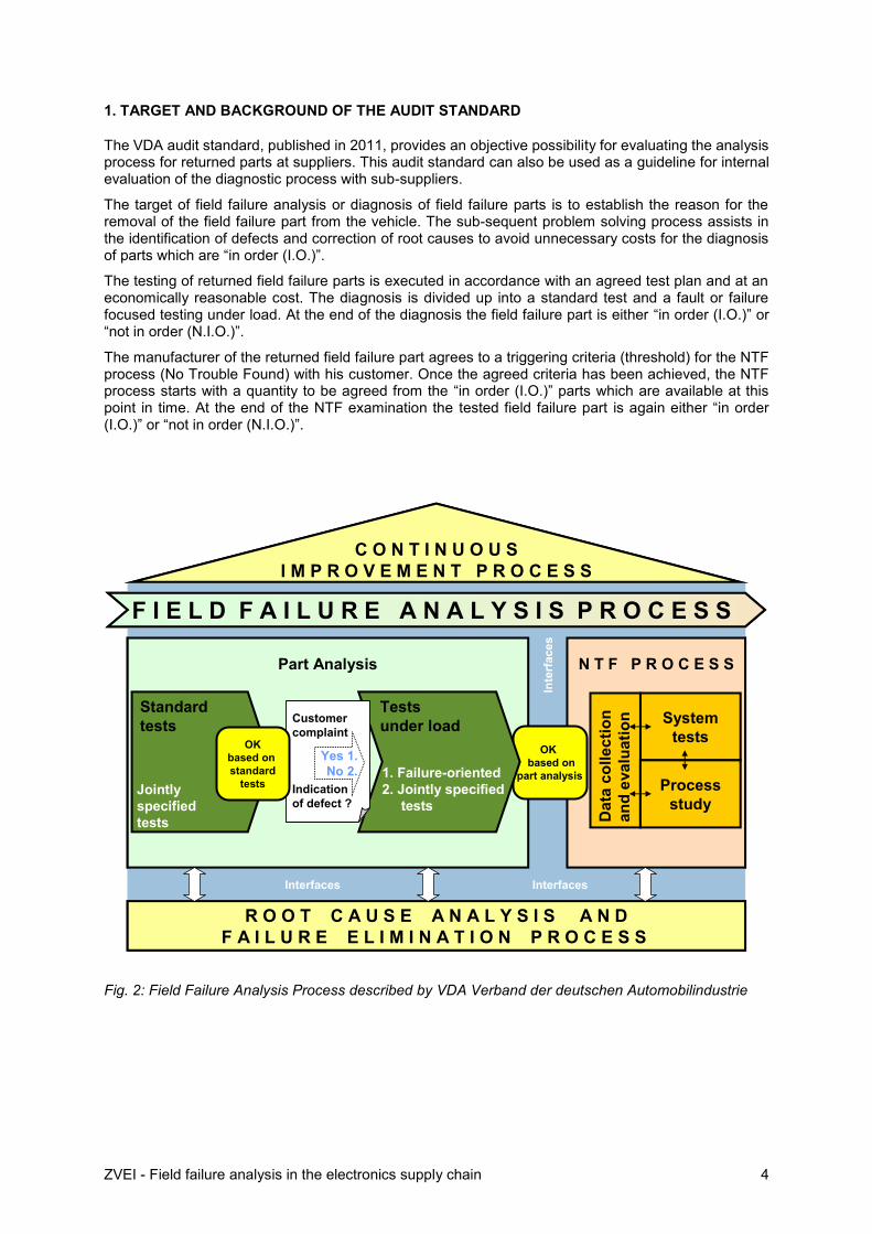
The target of field failure analysis or diagnosis of field failure parts is to establish the reason for the removal of the field failure part from the vehicle. The sub-sequent problem solving process assists in the identification of defects and correction of root causes to avoid unnecessary costs for the diagnosis of parts which are “in order (I.O.)”.
The testing of returned field failure parts is executed in accordance with an agreed test plan and at an economically reasonable cost. The diagnosis is divided up into a standard test and a fault or failure focused testing under load. At the end of the diagnosis the field failure part is either “in order (I.O.)” or “not in order (N.I.O.)”.
The manufacturer of the returned field failure part agrees to a triggering criteria (threshold) for the NTF process (No Trouble Found) with his customer. Once the agreed criteria has been achieved, the NTF process starts with a quantity to be agreed from the “in order (I.O.)” parts which are available at this point in time. At the end of the NTF examination the tested field failure part is again either “in order (I.O.)” or “not in order (N.I.O.)”.
Fig. 2: Field Failure Analysis Process described by VDA Verband der deutschen Automobilindustrie
Interfaces Interfaces
Inte
rface
s
Part Analysis
R O O T C A U S E A N A L Y S I S A N D
F A I L U R E E L I M I N A T I O N P R O C E S S
Standard
tests
N T F P R O C E S S
System
tests
Jointly
specified
tests
F I E L D F A I L U R E A N A L Y S I S P R O C E S S
C O N T I N U O U S
I M P R O V E M E N T P R O C E S S
Da
tac
oll
ec
tio
n
an
d e
va
lua
tio
n
Process
study
OK
based on
part analysis
Tests
under load
1. Failure-oriented
2. Jointly specified
tests
Customer
complaint
Indication
of defect ?
Yes 1.
No 2.
OK
based on
standard
tests

ZVEI - Field failure analysis in the electronics supply chain 5
2. DEFINITION OF TERMS
Analysis:
Vehicle component and system supplier: o Testing of field failure parts according to an agreed test plan and test instructions o Failure analysis (Ausfallanalyse): testing of customer relevant vehicle functions
Manufacturer of electronics components and parts: o Electrical test: non-destructive testing o Physical analysis: destructive testing as a rule (analysis of the cause)
Diagnosis / Part Analysis (Befundung): Testing of a field failure part in accordance with VDA recom-mendation "Field Failure Analysis", meaning a standard test with sub-sequent testing under load (agreed jointly or failure focused)
Failure (Ausfall): A vehicle component does not function as expected in the vehicle
Fault or Defect (Fehler): Component does not meet the specified characteristics or parameters (see "ZVEI Zero Defect Guideline")
Field complaint: A vehicle component has to be replaced or a repair has to be carried out in the work-shop due to a customer complaint or an error message
Field failure part (Schadteil Feld): Due to a field complaint, the field failure part is removed from the faulty vehicle and made available to the supplier. Depending on the sample rules in the reference mar-ket, the sample rate for part return can amount between 0% and 100%.
NTF process: Carrying out an NTF investigation with an NTF team and in accordance with the NTF guideline. The progress and results of the NTF investigation are recorded in an NTF report.
NTF part: An “in order (I.O.)” part which was transferred into the NTF process after reaching an NTF threshold or triggering criteria. If no fault was found on completion of the NTF investigation, the part is once again marked as “in order (I.O.)”
Part “in order (I.O.)”: No fault has been detected during the diagnosis
Part “not in order (N.I.O.)”: A fault or faulty function has been detected during the analysis, test or diagnosis
Sample parts: Field failure parts returned by random selection from the agreed reference market. Parts returned from outside of the reference market are called “testing material” or “special parts”
ZVEI - Field failure analysis in the electronics supply chain 6
3. QUESTIONNAIRE FOR THE ELECTRONICS SUPPLY CHAIN IN ACCORDANCE WITH VDA
Extract from VDA "field failure part analysis - audit standard", October 2011, chapter 1:
Requirements ...are found in separate accounts of current questionnaires and measurement criteria, e.g.
VDA-MLA – 4.2.5
VDA 6.3 – P7.5
ISO/TS 16949:2009 – 8.5.2.4
Given that it is based on VDA 6.3, already qualified auditors with the appropriate expertise can implement these process audits immediately. … the subject, field failure analysis, is handled in section:
P7: Customer Support, Customer Satisfaction, Service
Question 7.5: Is there a process which effectively guarantees the field failure process?
End of extract.
The audited organisation is free to present the result of the audit to other customers.
An evaluation of less than 80% may, according to VDA, result in the diagnostic process of the manufac-turer of the field failure part being evaluated as "not capable" and the testing results of previously re-turned field failure parts can thus be questioned once again by the customer. On the other hand, ques-tion 7.5 of the process audit according to VDA 6.3 is evaluated with a maximum of six points out of ten in this case.
3.1 PLANNING THE FIELD FAILURE ANALYSIS
3.1.1 FIELD FAILURE ANALYSIS PROCESS
3.1.1.1 PROCESS DESCRIPTION
The Field Failure Analysis process is described explicitly in the manufacturer’s quality management manual and in a similar way as done for the problem solving process or when dealing with customer complaints.
The management process and responsibilities result from the process description.
The Field Failure Analysis process describes the diagnosis, the NTF process, the problem analysis and lessons-learned, where the definition of these interfaces between the process steps and the accompa-nying flow of information are particularly important.
3.1.1.2 IMPLEMENTATION IN THE ORGANISATION
The Field Failure Analysis process is an element of the quality management policies, in line with ISO/TS 16949 for example.
Interfaces to other company processes should be visible.
ZVEI - Field failure analysis in the electronics supply chain 7
3.1 PLANNING OF THE FIELD FAILURE ANALYSIS
The Field Failure Analysis process is integrated within the product engineering process (including spe-cific test and verification processes and the corresponding equipment).
The subsequent contents are specifically planned for each product, documented and coordinated with the customer.
The planning and documentation of the field failure analysis process occurs in line with the requirements of the QM handbook.
The coordination of the product specific test contents between the supplier and the customer is very important for the acceptance of the test results. In particular shall be considered that “in order (I.O.)” field failure parts remain the property of the customer during the entire diagnosis process. If field failure parts are lost or damaged without the consent of the customer, this may result in this field failure part being classified as “not in order (N.I.O.)”.
The coordination of the field failure analysis test plan occurs at the time of initial sample approval (e.g. EMPB or PPAP). In this way it can be assured that the diagnosis process is available with the necessary resources when the first field failure parts are returned from saleable vehicles.
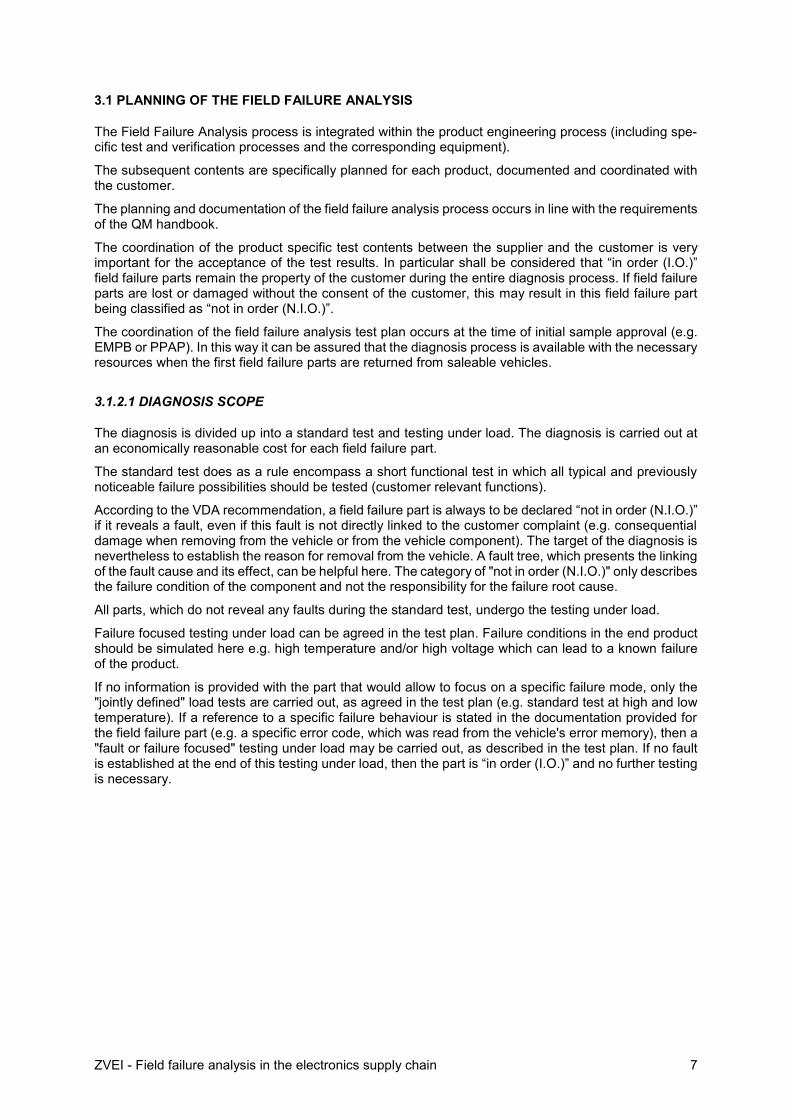
3.1.2.1 DIAGNOSIS SCOPE
The diagnosis is divided up into a standard test and testing under load. The diagnosis is carried out at an economically reasonable cost for each field failure part.
The standard test does as a rule encompass a short functional test in which all typical and previously noticeable failure possibilities should be tested (customer relevant functions).
According to the VDA recommendation, a field failure part is always to be declared “not in order (N.I.O.)” if it reveals a fault, even if this fault is not directly linked to the customer complaint (e.g. consequential damage when removing from the vehicle or from the vehicle component). The target of the diagnosis is nevertheless to establish the reason for removal from the vehicle. A fault tree, which presents the linking of the fault cause and its effect, can be helpful here. The category of "not in order (N.I.O.)" only describes the failure condition of the component and not the responsibility for the failure root cause.
All parts, which do not reveal any faults during the standard test, undergo the testing under load.
Failure focused testing under load can be agreed in the test plan. Failure conditions in the end product should be simulated here e.g. high temperature and/or high voltage which can lead to a known failure of the product.
If no information is provided with the part that would allow to focus on a specific failure mode, only the "jointly defined" load tests are carried out, as agreed in the test plan (e.g. standard test at high and low temperature). If a reference to a specific failure behaviour is stated in the documentation provided for the field failure part (e.g. a specific error code, which was read from the vehicle's error memory), then a "fault or failure focused" testing under load may be carried out, as described in the test plan. If no fault is established at the end of this testing under load, then the part is “in order (I.O.)” and no further testing is necessary.
ZVEI - Field failure analysis in the electronics supply chain 8
3.1.2.2 DIAGNOSIS IN THE SUPPLY CHAIN
The diagnosis should check for customer relevant product characteristics:
The OEM provides the concern symptom and error description, as expressed by the workshop or the end customer
Tier 1 verifies the customer relevant functionality of the vehicle component, identifies and doc-uments the faulty function of a sub-component, if applicable.
Tier 2 checks the properties of the electronic module or electronic component which has caused the failure in the tier 1 vehicle component
Any pre-diagnosis, including the removal of electronic components (e.g. swap) at the Tier 1, should be coordinated with the component manufacturer
3.1.2.3 Triggering CRITERIA FOR THE NTF PROCESS
The NTF process is in principle triggered once a previously agreed threshold is reached, e.g.
a specific percentage of the analysed field failure parts are found “in order (I.O.)” within a defined period of time
the first returned field failure parts from a new product launch are found “in order (I.O.)” and shall be examined more closely e.g. verification of the workshop repair process or behaviour of the vehicle component in the system environment
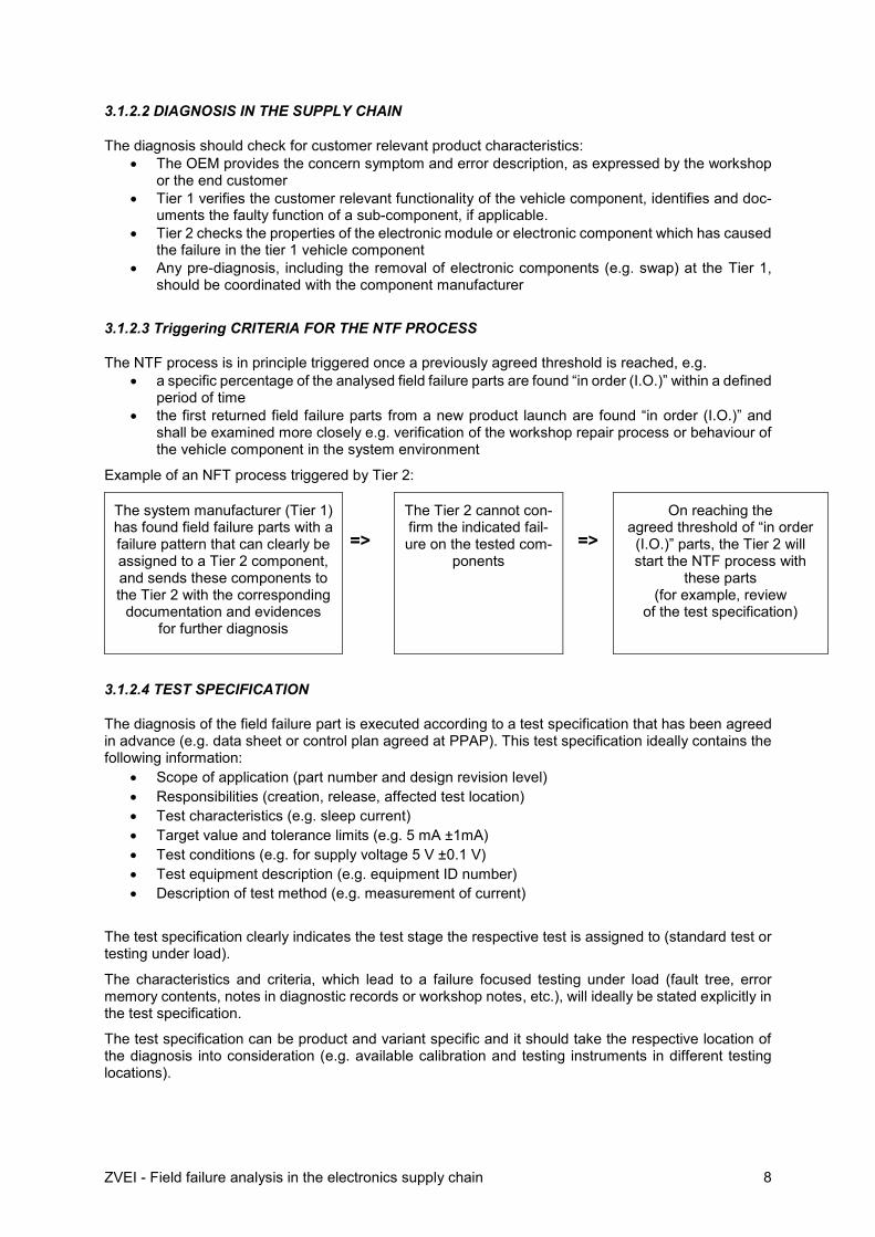
Example of an NFT process triggered by Tier 2:
The system manufacturer (Tier 1) has found field failure parts with a failure pattern that can clearly be assigned to a Tier 2 component, and sends these components to the Tier 2 with the corresponding
documentation and evidences for further diagnosis
=>
The Tier 2 cannot con-firm the indicated fail-ure on the tested com-
ponents
=>
On reaching the agreed threshold of “in order (I.O.)” parts, the Tier 2 will start the NTF process with
these parts (for example, review
of the test specification)
3.1.2.4 TEST SPECIFICATION
The diagnosis of the field failure part is executed according to a test specification that has been agreed in advance (e.g. data sheet or control plan agreed at PPAP). This test specification ideally contains the following information:
Scope of application (part number and design revision level)
Responsibilities (creation, release, affected test location)
Test characteristics (e.g. sleep current)
Target value and tolerance limits (e.g. 5 mA ±1mA)
Test conditions (e.g. for supply voltage 5 V ±0.1 V)
Test equipment description (e.g. equipment ID number)
Description of test method (e.g. measurement of current)
The test specification clearly indicates the test stage the respective test is assigned to (standard test or testing under load).
The characteristics and criteria, which lead to a failure focused testing under load (fault tree, error memory contents, notes in diagnostic records or workshop notes, etc.), will ideally be stated explicitly in the test specification.
The test specification can be product and variant specific and it should take the respective location of the diagnosis into consideration (e.g. available calibration and testing instruments in different testing locations).

ZVEI - Field failure analysis in the electronics supply chain 9
3.1.2.5 DESTRUCTIVE TESTS
The tested field failure part must not be damaged in the standard test or in the jointly defined testing under load. The principle that the field failure part which is analysed is possibly “in order (I.O.)” and can be installed back into a vehicle for further NTF examination if necessary. Many vehicle manufacturers demand the prompt return of “in order (I.O.)” parts.
The delivery condition of the field failure part must be saved at reception. It shall be possible to restore at any time the exact same condition, as far as possible, for example:
Software version and status
Parameters
Error memory contents
Application data
A destructive test should only be carried out after prior agreement between the customer and the sup-plier. The test stage from which possible damage of the defective part occurs in a way that the part be unusable for further vehicle testing, shall ideally be visible in the test plan. The test report shall always allow to see which tests have been carried out for each field failure part.
It is possible that electronic components will be damaged when they are removed from electronic mod-ules. The precise procedure for their removal shall be agreed between the customer and the manufac-turer and the test personal shall be trained accordingly.
3.2 DIAGNOSIS OF THE FIELD FAILURE PART
The diagnosis of the field failure part starts with receipt of goods at the supplier and ends with informing the customer about the test result "in order (I.O.)” or “not in order (N.I.O.)” after diagnosis.
3.2.1 TESTING AND DOCUMENTATION
3.2.1.1 INCOMING GOODS
The reception of field failure parts and associated documents is a well-organized process. If a received field failure part is unknown or cannot be assigned to any test specification, the customer is informed about this promptly.
Incoming goods shall be verified according to the following criteria, for example:
Damaged or contaminated ?
Completeness and packaging correct (e.g. ESD protection) ?
Agreed documentation available (e.g. tags, labels, workshop diagnostic records etc.) ?
Recording of the essential information and completion of the complaint data
If any deviation from the agreed requirements is observed, the customer will be informed promptly in order to complete the missing information, so that the diagnosis is not delayed unnecessarily.
3.2.1.2 LOGISTICS
Only a small random sample of failure parts is returned from the field. These parts must be handled very carefully as they might be used for the later calculation of a technical responsibility rate. Damaged or lost field failure parts are as a rule charged to the recipient of the goods (supplier).
Field failure parts must be individually identified so that they can be distinguished from other parts in the analysis process, e.g. returns from 0-km or production line failures. It should be clear where a field failure part is located at all times (individual marking).

ZVEI - Field failure analysis in the electronics supply chain 10
A well-organized workflow can help to ensure an agreed sequence of tests or to communicate interim results.
Any return of the field failure part back to the customer, passing on to a supplier or external laboratory or scrapping of the field failure part shall be well documented and the corresponding evidences shall be archived.
Work instructions and authorisation for transport, handling and storage are recommended (e.g. ESD protection). The field failure parts must be protected against vandalism and theft in particular.
3.2.2 PARTS ANALYSIS PROCESS
Each field failure part is clearly assigned to a test specification. The design revision level of the part shall be taken into consideration in this test specification (e.g. change of the software version).
The returned field failure part (as removed from the vehicle) can be different from the original configu-ration at series delivery (e.g. software updates in the vehicle or backwards compatible spare parts). The test specification shall take into account such potential evolution of the field failure part during the prod-uct life cycle.
If the field failure part is set back to the original delivery configuration, the parties can agree to restore the condition of the returned field failure part at any time.
The planning of the diagnosis sequence is assessed in chapter 2.2 of the VDA audit standard. The corresponding implementation and documentation is assessed in chapter 2.3:
Separate sequence of standard and load test, complete implementation in the planned test se-quence
Assignment of test structures, test equipment, test methods and specifications
Defined limits for all test characteristics
Testing of all relevant functions
Simulate specific usage conditions (system environment)
Identify destructive tests
Assessment of the customer complaint for the load test
Plausibility check of the test result with the customer complaint
The test results must be recorded and statistically evaluated if required.
3.2.3 RESOURCES
3.2.3.1 STAFF RESOURCES
Responsibilities and authorisations should be recorded as well as absence management. Contact per-sons in internal specialist areas and at the customer's premises should be identifiable.
The employees should have verifiable qualifications and training for specialist analysis of the products entrusted to them.
It is recommended to monitor the staff workload so that the necessary capacities can be planned.
3.2.3.2 MATERIAL RESOURCES
Suitable test equipment and devices should be available in sufficient quantities and they should be subject to regular checks and calibration.

ZVEI - Field failure analysis in the electronics supply chain 11
3.2.4 EFFICIENCY OF THE DIAGNOSIS
3.2.4.1 KEY PERFORMANCE INDICATORS (KPI)
The following key performance indicators shall be mandatory according to VDA recommendation: Average diagnosis time: Time from the receipt of goods until completion of the diagnosis of the
field failure part (standard test and testing under load) Proportion of “in order (I.O.)” parts after diagnosis compared to the total number of parts sub-
jected to diagnosis
It is recommended to monitor the efficiency of the diagnosis process.
The primary objective of the joint NTF process is to identify the root cause and responsibility of the vehicle failure. The normally agreed diagnosis lead time does not apply to the NTF process, because it is impossible to estimate in advance the time and effort needed for joint special testing and application evaluation.
3.2.4.2 EFFECTIVENESS
The key performance indicators which have been recorded could be used for control of the diagnosis process and for the escalation of problems.
Newly gained knowledge should be taken into consideration in the diagnosis process, e.g. adaptation of test specifications or failure focused testing under load after execution of an NTF process or lessons learned.
3.2.4.3 RESULT OF THE DIAGNOSIS
The results of the diagnosis are recorded as "not in order (N.I.O.)" or "in order (I.O.) according to diag-nosis". In line with the VDA recommendation, a “not in order (N.I.O.)” diagnosis does not automatically mean that the responsibility for the fault is assumed (e.g. EOS damage).
The rules for communication should be agreed explicitly with the customer:
Quality reports
Test records
Entries in the customer system
Archiving of the data
Evaluation of the data (Pareto, Paynter, etc.)
Further use of the parts should be documented in accordance with the customer agreement:
Placing in closed storage
Proof of dispatch
Proof of disposal or scrap

ZVEI - Field failure analysis in the electronics supply chain 12
3.3 NTF PROCESS
When an NTF trigger criterion is reached, field failure parts with the results "in order (I.O.) according diagnosis" are handed over to the NTF process. No “in order (I.O.)” parts should be sent from Tier 1 to the Tier 2 supplier in the normal diagnosis process.
NTF parts can be grouped under the assumption that the same reason for complaint for all parts has led to their removal from the vehicle. If it becomes clear during the NTF examination that there are several reasons, the group will be subdivided accordingly. The information provided with the field failure part (e.g. error memory entries or workshop notes) is the decisive factor for this grouping.
In accordance with the VDA recommendation, both the customer and the supplier can carry out the NTF process independently from each other. First of all the VDA recommends an independent NTF exami-nation at the premises of the party for which the NTF triggering criterion is met.
At the end of the NTF examination the field failure part is either “in order (I.O.)” or “not in order (N.I.O) according to NTF examination”.
When electronic components are handed over to the manufacturer, the reason for the complaint should always be described. Special analyses are coordinated jointly during the NTF examination, see also the following JEDEC documents (www.jedec.org):
- JEP-123 – Guideline for Measurement of Electronic Package Inductance and Capacitance Model Parameters (1995)
- JEP-134 – Guidelines for Preparing Customer-Supplied Background Information Relating to a Semiconductor-Device Failure Analysis (1998)
- JESD671a – Component Quality Problem Analysis and Corrective Action Requirements (In-cluding Administrative Quality Problems)
3.3.1 NTF GUIDELINE
The NTF investigation should in principle involve teamwork which goes beyond the area of competence of the analysis staff for the normal diagnosis. According to the VDA recommendation, an NTF guideline is available within the organisation that carries out the NTF project so that this investigation can be described and documented from the beginning until the end.
The NTF team should have complete knowledge of the vehicle application for every involved component (e.g. vehicle models in which the product is used) including any usage as carry-over part. Important changes in the product environment should also be known.
- A mission profile should be known for each application of the product, taken into consideration in the diagnosis test plan and also documented accordingly in the PPAP.
- A joint action plan shall be agreed for carrying out the NTF examination. - A guideline should contain the following points (see also VDA recommendation):
Data summary and evaluation of internal quality information
o Necessary data to be provided (both parties)
o Description of the test equipment used at the customer
o Code revisions of application software or special software used
o Referenced specification and data sheet values
o Part or application revision level
o Time in service
o Point of failure, mileage, before or after vehicle assembly, before or after assembly in vehicle component etc.
o Field data analysis from worldwide complaints
o Vehicle and environmental conditions resp. special conditions for application
o Product life history

ZVEI - Field failure analysis in the electronics supply chain 13
Definition of test criteria
o Verify and understand the problem description
o Reproduce failure conditions on appropriate test bench
o Comparability check of tests
Application review
o Mission profile and changes
o Review of the process flow in the complete supply chain
NTF investigation including potential extra testing
o Timeline for the NTF investigation
o Agreement of extra testing for the defective parts
o Agreement of extra testing for the component in application environment
o Criteria for termination of the NTF investigation
o Reporting (see case studies)
Sponsorship in the organisation
o Define and review the milestones
o Escalation flow

ZVEI - Field failure analysis in the electronics supply chain 14
3.3.2 NTF INVESTIGATION
According to VDA the NTF investigation covers three work packages:
Data collection and assessment: Supplier and customer evaluate all available data which could enable an isolation or more accurate description of the reason for the complaint (e.g. MOPMIS charts or alignment with quality data for internal production).
Process evaluation: handling and work process instructions from component delivery and vehicle assembly until removal from the vehicle and return to manufacturer
System evaluation: behaviour of the assembly in the system environment or in the vehicle under operating conditions
The VDA recommends the use of project management methods for carrying out the NTF process:
NTF team and assigned contact persons for the supplier and customer
Action plan with due dates and responsibilities
Regular review meetings and reports
Jointly defined time frame for the respective process steps and final report
Staff and material resources for the NTF examination should be assured. The NTF team should in par-ticular have access to the necessary data for statistical evaluation and access to process and system evaluation (e.g. vehicles or subsystem structures).
3.4 PROBLEM ANALYSIS
Field failure parts for which a reason for failure in the vehicle was established "not in order (N.I.O)" at the end of the diagnosis or after execution of the NTF process, are handed over to the problem solving process of the party who is presumed to be responsible for the failure:
Root cause analysis Corrective action Verification of effectiveness
The communication of all important information must be assured during this handover e.g.
Description of the failure mechanism and effect (in the vehicle) Assignment of new field failure parts to failures which are already known Handling of new failure patterns
The problem solving process should be carried out independent from the diagnosis and NTF process. The lead time for the diagnosis agreed with the customer only refers to the diagnosis (standard test and testing under load).
ZVEI - Field failure analysis in the electronics supply chain 15
4. CASE STUDIES
The below examples shall briefly clarify the NTF process report and the respective final diagnosis results and conclusions. Two case studies are attached using the formal structured NTF report.
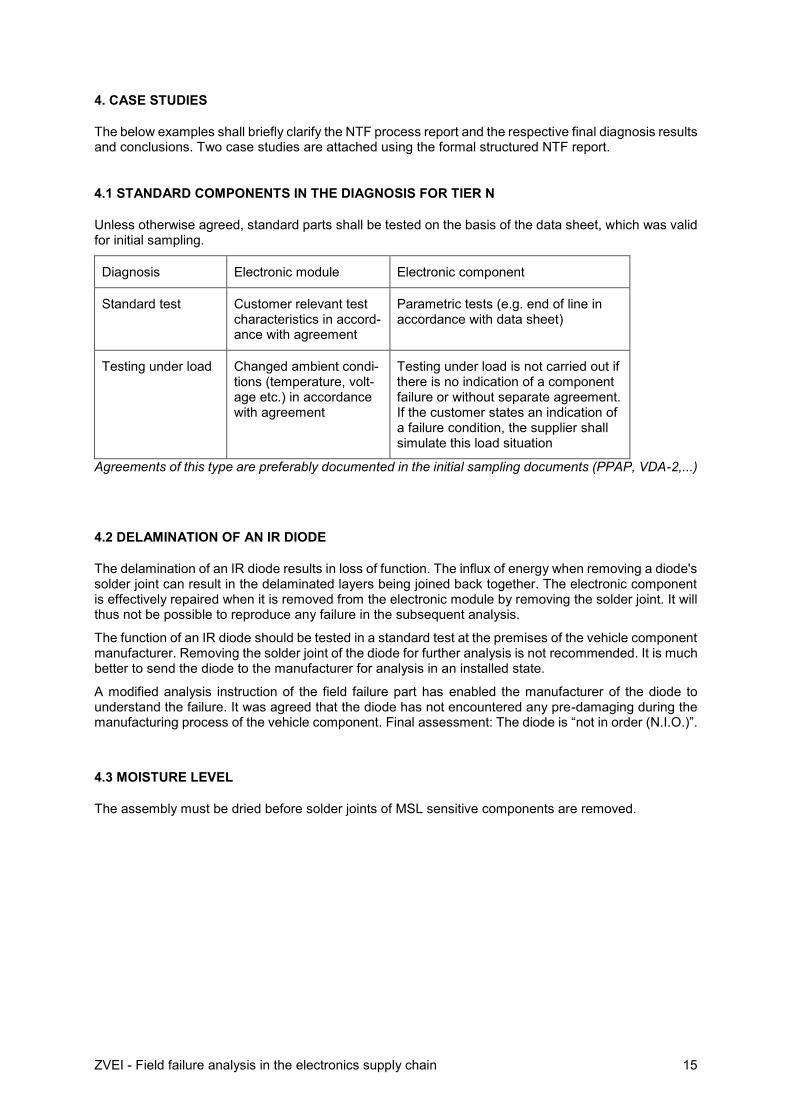
4.1 STANDARD COMPONENTS IN THE DIAGNOSIS FOR TIER N
Unless otherwise agreed, standard parts shall be tested on the basis of the data sheet, which was valid for initial sampling.
Diagnosis Electronic module Electronic component
Standard test Customer relevant test characteristics in accord-ance with agreement
Parametric tests (e.g. end of line in accordance with data sheet)
Testing under load Changed ambient condi-tions (temperature, volt-age etc.) in accordance with agreement
Testing under load is not carried out if there is no indication of a component failure or without separate agreement. If the customer states an indication of a failure condition, the supplier shall simulate this load situation
Agreements of this type are preferably documented in the initial sampling documents (PPAP, VDA-2,...)
4.2 DELAMINATION OF AN IR DIODE
The delamination of an IR diode results in loss of function. The influx of energy when removing a diode's solder joint can result in the delaminated layers being joined back together. The electronic component is effectively repaired when it is removed from the electronic module by removing the solder joint. It will thus not be possible to reproduce any failure in the subsequent analysis.
The function of an IR diode should be tested in a standard test at the premises of the vehicle component manufacturer. Removing the solder joint of the diode for further analysis is not recommended. It is much better to send the diode to the manufacturer for analysis in an installed state.
A modified analysis instruction of the field failure part has enabled the manufacturer of the diode to understand the failure. It was agreed that the diode has not encountered any pre-damaging during the manufacturing process of the vehicle component. Final assessment: The diode is “not in order (N.I.O.)”.
4.3 MOISTURE LEVEL
The assembly must be dried before solder joints of MSL sensitive components are removed.

ZVEI - Field failure analysis in the electronics supply chain 16
4.4 OXYGEN SENSOR NOT FUNCTIONING
Source: AIAG CQI-14 – Use Case Studies, March 2010
The oxygen sensor in the exhaust system is detected defective by the vehicle controller which results in a display message on the dashboard. The failure has a frequency of 7.5 C/1000 (IPTV), with 78% of complaints occurring within the first 5,000 miles. The sensors do not show any failure in the diagnosis (“in order”) once the agreed standard test and testing under load have been carried out. An NTF examination is started. During this examination it becomes apparent that the contact blades of the sensor are scratched. An examination of the manu-facturing process reveals the risk of a defective cable connection. The sensor is subsequently exam-ined with a special focus on intermittent electrical contacts and the risk of failure is confirmed. Follow-ing optimisation of the manufacturing process for the sensor plug contacts, the failure frequency was reduced to 0 C/1000. Final assessment: The sensor is “not in order (N.I.O.)”. As a result of the NTF process, the failure root cause was corrected just 90 days after it first occurred in a vehicle.
4.5 RANDOMLY OCCURING SPIKES ON OUTPUT
Problem description: Automatic Test Equipment (ATE) and Bench Testing showed that the returned five unit are passing all test parameters and are functional. Oscilloscope monitoring at the output further verified that the returned units are functional and showing no sign of output anomaly. Bench testing using noise test set-up further verified that the returned units are not exhibiting noisy output.
Analysis result: Tests good, passed upon retest, no trouble found.
Analysis Methodology: Customer returned further good and ‘bad’ examples along with further test de-tails. Further analysis by the product line was able to replicate the spikes at the output of the returned units by building new test boards based on the Customer test circuitry. Conclusion: The characteristic observed by the customer on these returned units are typical of this device and are within Datasheet specification. Customer application set-up and used screening test is exceeding the datasheet specifi-cation.
Final statement: Parts are I.O.
Recommendation and next steps: Customer to review internal test specification in order to avoid rejec-tion of I.O. parts.
4.6 LINE FAILURE AT LOW TEMPERATURE TEST WITH A HIGH VOUT SIGNAL
Problem description: Automatic Test Equipment (ATE) was used to test the returned units for conform-ance to datasheet with electrical specifications. ATE results showed that the returned units were already programmed. External visual examination and I-V curve trace analysis on all units did not reveal any anomalies.
Analysis result: no trouble found
Analysis Methodology: Bench test using the customer set up and a temperature sweep from 125 °C to – 40 °C temperatures showed an anomaly on the output voltage (Vout) at cold temperatures for some of the returned units. ATE and bench testing showed for some of the returned units are electrically good meeting datasheet electrical specifications and showing no signs of output (Vout) failures at cold tem-peratures.
Final statement: Parts are N.I.O.
Failure root cause of occurrence: Random fab defect

ZVEI - Field failure analysis in the electronics supply chain 17
4.7 FUNCTIONAL DEFECTS IN THE ENGINE'S GAS AND AIR SUPPLY SYSTEM
Source: AIAG CQI-14 – Use Case Studies, March 2010
Fuel injection nozzles had been replaced after approx. 10,000 km within a short production period and with a failure rate ten times higher than expected. The workshop analysis suggested that misfires oc-curred at low and high temperatures. In many cases the engine control warning light also came on and vehicles repeatedly came to the workshop with the same defect again. As well as the injection nozzles, spark plugs, gaskets and cylinder heads were replaced, sometimes repeatedly.
An initial measure involved increasing the quantity of returned parts from the production period con-cerned. The first 131 parts received were intensively tested on an engine test bench. Three parts failed as metal residue was found. All three parts were made on the same day.
The remaining 128 injection nozzles remained fully functional after the intensive test and without any root cause related to the complaint.
An evaluation of the test results for spark plugs revealed that many spark plugs from the same produc-tion period were heavily sooted. The OEM has then focused the root cause analysis towards the regu-lation of the air-fuel mixture.
Final assessment: the injection nozzles are “in order (I.O.)”.
5. LIST OF ABBREVIATIONS
AIAG Automotive Industry Action Group
CLEPA European Association of Automotive Suppliers (Comité de Liaison Européen des Fabricants d’Equipements et de Pièces Automobiles)
EMPB Erstmusterprüfbericht (initial sample report or PSW Part Submission Warrant)
I.O. in order (OK)
N.I.O. not in order (NOK)
NTF No-Trouble-Found
PPAP Production Part Approval Process
Field failure part Defective part (removed from the vehicle)
VDA Verband der deutschen Automobilindustrie (German Automotive Industry Association)
ZVEI Zentralverband der Elektrotechnik- und Elektronikindustrie (Professional Association for Electronic Components and Systems)
6. APPENDIX 1 – CASE STUDIES AS NTF REPORT
Example 1: Randomly occurring defect page 18+19
Example 2: Test coverage at cold page 20+21

ZVEI - Field failure analysis in the electronics supply chain 18
Customer: ABC
Issue Description: Randomly occurring defect
Date: 01 Jul. 2012
Process Start Date: 14. Feb 2012 Process Closure Date: 15. Jun 2012
Member Type Name Department
ABC A SQM
B Project Leader
Company C Quality
D Product Engineering
Additional Departments Represented On the Team:
FA/PA Engineers
Customer Application: Control unit NTF Triggering criteria: 3 units within 3 months
Customer Point of Failure: Production line Quantity of failure: 5
Customer Part Number: C223344 Magnitude e.g. (xC/1000) IPTV: 140ppm
Customer Ref Number: REJ87654 Serial Number: Chop01
Company Part Number: PRECISION RAIL-RAIL CHOP-PER OPAMP
Lot IDs: C55321
Time in field: 0 Date Codes: 1204
Description of the main Failure:
Randomly occurring defect, spikes at the output.
Initial analysis action steps:
ATE and Bench Testing showed that the returned 5 unit are passing all test parameters and are func-tional. Oscilloscope monitoring at the output further verified that the returned units are functional and showing no sign of output anomaly. Bench testing using noise test set-up further verified that the re-turned units are not exhibiting noisy output. Conclusion: Tests Good, Passed upon retest, NTF
(module, part, specification, test, mission profile, environment, change history, manufacturing pro-cess…)
Customer returned further good and “bad” examples along with further test details. Further analysis by the product line was able to replicate the spikes at the output of the returned units by building new test boards based on the Customer test circuitry. Conclusion: The characteristic observed by the customer on these returned units are typical of this device and are within Datasheet specification. Customer Application set up and used screening test is exceeding the datasheet specification.
1: Teams involved
2: Issue Details
3: The analysis methodology:

ZVEI - Field failure analysis in the electronics supply chain 19
Action Owner Date Status/Results
ATE and Bench Testing Company 8. May 2012 passing all test parameters and are func-
tional
building new test boards based on the Customer test circuitry
Company 12. May 2012 replicate the spikes at the output
Root Cause:
Customer Application set up and used screening test is exceeding the datasheet specification.
Final Statement: I.O. N.I.O.
Recommendation/next steps: ABC to review internal specification in order to meet Datasheet
Name Department Date
Company and ABC June 15 2012
4: Summary of tests, parameters and processes examined and analysis results:
5: Final Team meeting
No Trouble
Found
Application at Customer
Product
Customer cir-cuity
Likely: simulation of customer schematic confirmed spikes. Spikes are within Datasheet specs
Unlikely: Explanation / simulation results
Unlikely: Explanation / simulation results
Meet datasheet
spec
Unlikely: Explanation / simulation results
Unlikely: Explanation / simulation results
Unlikely: Explanation / simulation results
Low possibility: Explanation / simulation re-
sults
Problem / Defect
Potential Areas
Primary Con-tributors
Secondary Con-tributors
Analysis or Val-idations
Spikes at the
output

ZVEI - Field failure analysis in the electronics supply chain 20
Customer: ABC
Issue Description: Test Coverage at Cold
Date: 15 Jul. 2013
Process Start Date: 20. Jan 2013 Process Closure Date:15.Jun 2013
Member Type Name Department
ABC A SQM
B Test Department
Company C Quality
D Product Engineering
E Test Manufacturing
F Test and Product Engineering
Additional Departments Represented On the Team: FA/PA Engineers
Customer Application: Control unit NTF Triggering criteria: >3 units within 3 months
Customer Point of Failure: Production line Quantity of failure: 17
Customer Part Number: Cust223311 Magnitude e.g. (xC/1000)
IPTV: 14 ppm
Customer Ref Number: REJ20132222 Serial Number: ProAMP 55
Company Part Number: Programmable Op Amp Lot IDs: B54321
Time in field: 0 Date Codes: 1250
Description of the main Failure: Line failure at low temperature test with a high Vout signal
Initial analysis action steps: Automatic Test Equipment (ATE) was used to test the returned units for conformance to datasheet electrical specifications. ATE results showed that the returned units were already programmed. External visual examination and I-V curve trace analysis on all units did not reveal any anomalies. Analysis conclusion NTF.
(module, part, specification, test, mission profile, environment, change history, manufacturing process…)
Review of Customer test and specification set up. Bench testing using the customer set up and a temperature sweep from 125 °C to - 40 °C temperatures showed an anomaly on the output voltage (Vout) at cold temperatures for some of the returned units.
ATE and bench testing showed for some of the returned units are electrically good meeting datasheet electrical specifications and showing no signs of output (Vout) failures at cold temperatures.
1: Teams involved
2: Issue Details
3: The analysis methodology:

ZVEI - Field failure analysis in the electronics supply chain 21
Action Owner Date Status/Results
ATE Testing Company 8. Feb 2013 passing all test parameters including cold
and are functional
Bench testing using the customer set up and a temperature sweep from
125 °C to – 40 °C Company 15. May 2013
anomaly on the output voltage (Vout) at cold temperatures for some of the re-
turned units
Root Cause:
The root cause of occurrence for this failure was detected as a random fab defect
Final Statement: I.O. N.I.O.
Recommendation/next steps: The corrective action to be defined in 8D Report
Name Department Date
Company and ABC, final presentation Quality / SQM 20 June 2013
4: Summary of tests, parameters and processes examined and analysis results:
5: Final Team meeting
No Trouble
Found
Application at Customer
Product
Customer cir-cuity
Custopmer test specifica-
tion
unlikely: circuit according to datasheet
Unlikely: test set up and limits according to-
datasheet
Unlikely: Explanation / simulation results
Meet datasheet
spec
likely: some parts failes with temp sweep at cold
Package is-sue
Unlikely: no mech defects detected
Unlikely: Explanation / simulation results
ESD Low possibility: no defect site on Die de-
tected
Fab Process
Likely: Deprocessing of units detected random fab defect
Problem / Defect
Potential Areas
Primary Con-tributors
Secondary Con-tributors
Analysis or Val-idations
Output signal too
high at cold tem-
erature

ZVEI - Field failure analysis in the electronics supply chain 22
ZVEI Zentralverband Elektrotechnik- und Elektroindustrie e.V. Professional Association for Electronic Components and Systems Lyoner Straße 9 60528 Frankfurt am Main, Germany
Telephone: +49 69 6302-354 Fax: +49 69 6302-407 email: [email protected] www.zvei.org/ecs P
ictu
re s
ourc
e: Z
VE
I