field guide instruction manual - minelab metal … instruction... · instruction manual field guide...
TRANSCRIPT

Instruction Manual
Field Guide
Turn on (p. 20)
Choose a Discrimination Pattern (pp. 30–35)
Adjust Sensitivity (p. 46) and Volume (p. 52)
Choose a Noise Cancel channel (p. 48)
Adjust Ground Balance (p. 56)
Begin detecting!
These quick start instructions allow you to begin detecting straight away and find important reference information for setting up your X‑TERRA.
Minelab encourages all users to read the entire manual to ensure a complete understanding of all the X‑TERRA features and functions.
Power Turns the detector On/Off.
Patterns Scrolls through the different Discrimination Patterns.
All Metal Toggles between the selected discrimination pattern and the All Metal pattern.
Minus Adjusts settings, and scrolls to the left through the discrimination segments.
Menu Enters the Menu. Accesses and scrolls through the detecting settings.
Plus Adjusts settings, and scrolls to the right through the discrimination segments.
Pinpoint/Detect Pinpoint assists in locating the exact position of a target prior to recovery. Detect exits menu settings and returns to detection.
Accept/Reject Accepts or rejects discrimination segments.
Ground Balance Accesses the Ground Balance Menu.
1
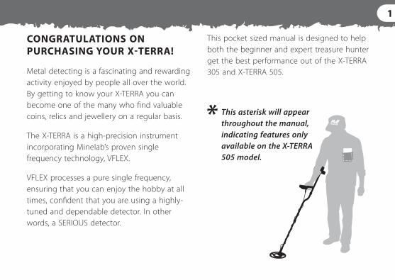
CONGRATULATIONS ON PURCHASING YOUR X‑TERRA!
Metal detecting is a fascinating and rewarding activity enjoyed by people all over the world. By getting to know your X‑TERRA you can become one of the many who find valuable coins, relics and jewellery on a regular basis.
The X‑TERRA is a high‑precision instrument incorporating Minelab’s proven single frequency technology, VFLEX.
VFLEX processes a pure single frequency, ensuring that you can enjoy the hobby at all times, confident that you are using a highly‑tuned and dependable detector. In other words, a SERIOUS detector.
This pocket sized manual is designed to help both the beginner and expert treasure hunter get the best performance out of the X‑TERRA 305 and X‑TERRA 505.
This asterisk will appear throughout the manual, indicating features only available on the X‑TERRA 505 model.
2 CONTENTS
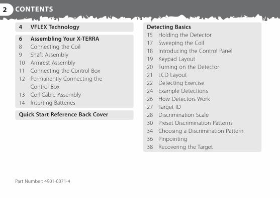
4 VFLEX Technology
6 Assembling Your X‑TERRA 8 Connecting the Coil 9 Shaft Assembly 10 Armrest Assembly 11 Connecting the Control Box 12 Permanently Connecting the Control Box 13 Coil Cable Assembly 14 Inserting Batteries
Quick Start Reference Back Cover
Detecting Basics 15 Holding the Detector 17 Sweeping the Coil 18 Introducing the Control Panel 19 Keypad Layout 20 Turning on the Detector 21 LCD Layout 22 Detecting Exercise 24 Example Detections 26 How Detectors Work 27 Target ID 28 Discrimination Scale 30 Preset Discrimination Patterns 34 Choosing a Discrimination Pattern 36 Pinpointing 38 Recovering the Target
Part Number: 4901‑0071‑4
3
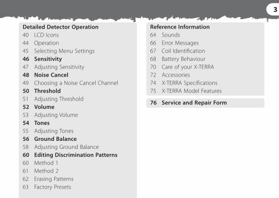
Detailed Detector Operation 40 LCD Icons 44 Operation 45 Selecting Menu Settings 46 Sensitivity 47 Adjusting Sensitivity 48 Noise Cancel 49 Choosing a Noise Cancel Channel 50 Threshold 51 Adjusting Threshold 52 Volume 53 Adjusting Volume 54 Tones 55 Adjusting Tones 56 Ground Balance 58 Adjusting Ground Balance 60 Editing Discrimination Patterns 60 Method 1 61 Method 2 62 Erasing Patterns 63 Factory Presets
Reference Information 64 Sounds 66 Error Messages 67 Coil Identification 68 Battery Behaviour 70 Care of your X‑TERRA 72 Accessories 74 X‑TERRA Specifications 75 X‑TERRA Model Features
76 Service and Repair Form

PRIMARY MICRO (IN CONTROL BOX) DIGITAL SIGNAL PROCESSING (DSP) CODEC SIGNAL CONVERSION
The 2nd generation X‑TERRA Series incorporate Minelab’s proven VFLEX Technology.
VFLEX uses state of the art digital and mixed‑signal components to enhance standard single frequency technology by replacing most of the analogue circuitry with digital signal processing. The small amount of analogue circuitry still employed has been very carefully designed and calibrated to obtain the outstanding sensitivity, stability and repeatability required to match the performance of the processing in the digital domain.
This radical departure from traditional approaches to metal detector design has been made possible by advances in electronics that power personal digital assistants, cell (mobile) phones and high‑fidelity portable audio equipment.
Analog Signal
Receive
Power Supply Audio
LCDKeypad
Transmit
Control Box
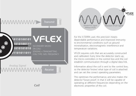
For the X‑TERRA user, this precision means dependable performance and improved immunity to environmental conditions such as ground mineralisation, electromagnetic interference and temperature variations.
VFLEX requires coils that are accurately constructed and calibrated. Every time the detector starts up, the micro‑controllers in the control box and the coil establish communication through a digital data link.
Information about the coil is sent to the control box, so the detector ‘knows’ what type of coil is attached and can set the correct operating parameters.
This optimises the performance, and also makes the detector ‘future proof ’, in that it will be capable of operating at different frequencies depending on the electronic properties of the coil.
Precision VFLEX SignalStandard VLF Signal (Without VFLEX)
SECONDARY MICRO (IN COIL) SENSING + TRANSMITTING COIL TYPE, SIZE, FREQUENCY
ReceiveAnalog Signal
Transmit
Coil
6
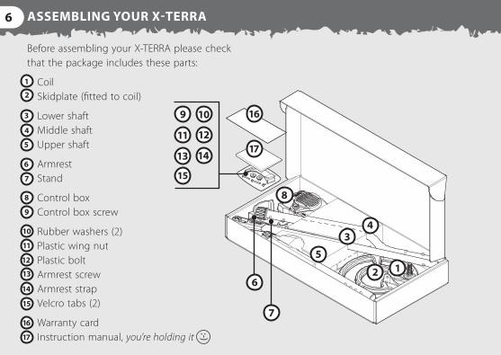
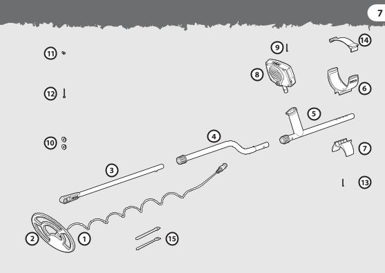
Before assembling your X‑TERRA please check that the package includes these parts:
Coil Skidplate (fitted to coil)
Lower shaft Middle shaft Upper shaft
Armrest Stand
Control box Control box screw
Rubber washers (2) Plastic wing nut Plastic bolt Armrest screw Armrest strap Velcro tabs (2)
Warranty card Instruction manual, you’re holding it
ASSEMBLING YOUR X‑TERRA
7
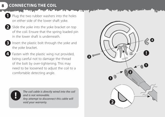
8 CONNECTING THE COIL
Plug the two rubber washers into the holes on either side of the lower shaft yoke.
Slide the yoke into the yoke bracket on top of the coil. Ensure that the spring loaded pin in the lower shaft is underneath.
Insert the plastic bolt through the yoke and the yoke bracket.
Fasten with the plastic wing nut provided, being careful not to damage the thread of the bolt by over‑tightening. This may need to be loosened to adjust the coil to a comfortable detecting angle.
The coil cable is directly wired into the coil and is not removable. Any attempt to disconnect this cable will void your warranty.
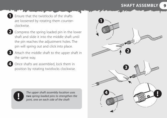
9SHAFT ASSEMBLY
Ensure that the twistlocks of the shafts are loosened by rotating them counter‑clockwise.
Compress the spring loaded pin in the lower shaft and slide it into the middle shaft until the pin reaches the adjustment holes. The pin will spring out and click into place.
Attach the middle shaft to the upper shaft in the same way.
Once shafts are assembled, lock them in position by rotating twistlocks clockwise.
The upper shaft assembly location uses two spring loaded pins to strengthen the joint, one on each side of the shaft
10 ARMREST ASSEMBLY
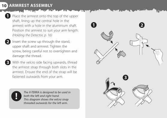
Place the armrest onto the top of the upper shaft, lining up the central hole in the armrest with a hole in the aluminium shaft. Position the armrest to suit your arm length. (Holding the Detector, p. 16)
Insert the screw up through the stand, upper shaft and armrest. Tighten the screw, being careful not to overtighten and damage the thread.
With the velcro side facing upwards, thread the armrest strap through both slots in the armrest. Ensure the end of the strap will be fastened outwards from your arm.
The X‑TERRA is designed to be used in both the left and right hand. This diagram shows the velcro strap threaded outwards for the left arm.
11CONNECTING THE CONTROL BOX
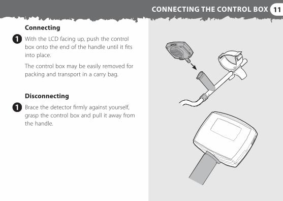
Connecting
With the LCD facing up, push the control box onto the end of the handle until it fits into place.
The control box may be easily removed for packing and transport in a carry bag.
Disconnecting
Brace the detector firmly against yourself, grasp the control box and pull it away from the handle.
12 PERMANENTLY CONNECTING THE CONTROL BOX
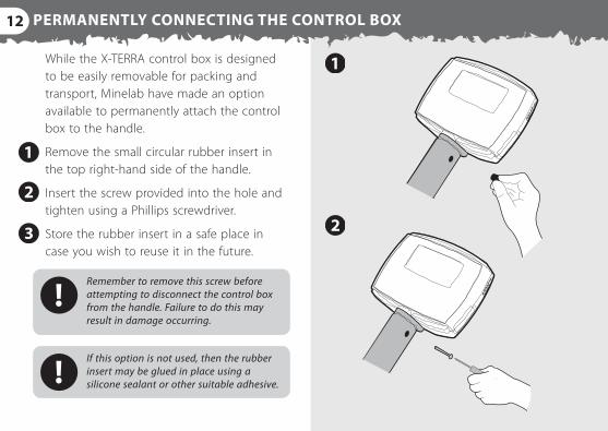
While the X‑TERRA control box is designed to be easily removable for packing and transport, Minelab have made an option available to permanently attach the control box to the handle.
Remove the small circular rubber insert in the top right‑hand side of the handle.
Insert the screw provided into the hole and tighten using a Phillips screwdriver.
Store the rubber insert in a safe place in case you wish to reuse it in the future.
Remember to remove this screw before attempting to disconnect the control box from the handle. Failure to do this may result in damage occurring.
If this option is not used, then the rubber insert may be glued in place using a silicone sealant or other suitable adhesive.
13
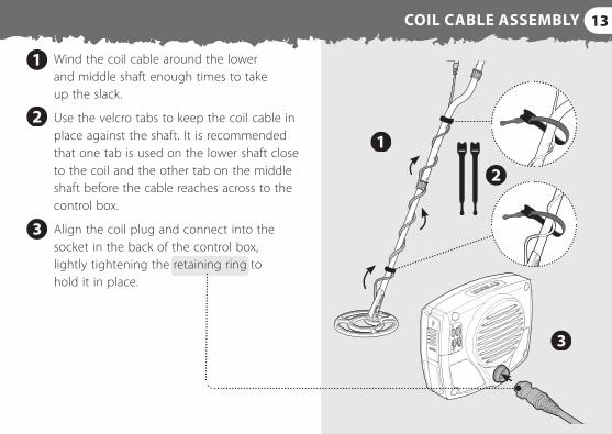
Wind the coil cable around the lower and middle shaft enough times to take up the slack.
Use the velcro tabs to keep the coil cable in place against the shaft. It is recommended that one tab is used on the lower shaft close to the coil and the other tab on the middle shaft before the cable reaches across to the control box.
Align the coil plug and connect into the socket in the back of the control box, lightly tightening the retaining ring to hold it in place.
COIL CABLE ASSEMBLY
14
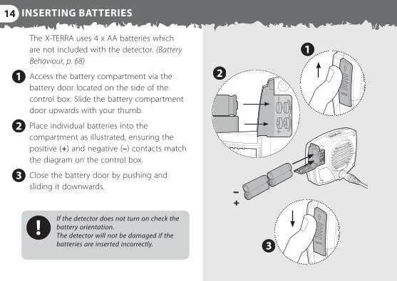
The X‑TERRA uses 4 x AA batteries which are not included with the detector. (Battery Behaviour, p. 68)
Access the battery compartment via the battery door located on the side of the control box. Slide the battery compartment door upwards with your thumb.
Place individual batteries into the compartment as illustrated, ensuring the positive (+) and negative (–) contacts match the diagram on the control box.
Close the battery door by pushing and sliding it downwards.
If the detector does not turn on check the battery orientation. The detector will not be damaged if the batteries are inserted incorrectly.
INSERTING BATTERIES
15HOLDING THE DETECTOR
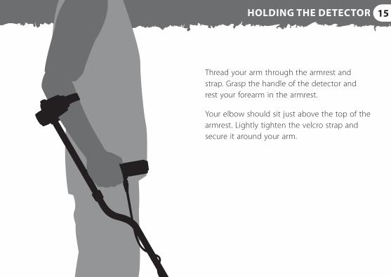
Thread your arm through the armrest and strap. Grasp the handle of the detector and rest your forearm in the armrest.
Your elbow should sit just above the top of the armrest. Lightly tighten the velcro strap and secure it around your arm.
16 HOLDING THE DETECTOR
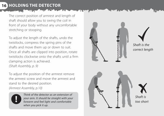
Shaft is the correct length
Shaft is too short
The correct position of armrest and length of shaft should allow you to swing the coil in front of your body without any uncomfortable stretching or stooping.
To adjust the length of the shafts, undo the twistlocks, compress the spring pins of the shafts and move them up or down to suit. Once all shafts are clipped into position, rotate twistlocks clockwise onto the shafts until a firm clamping action is achieved. (Shaft Assembly, p. 9)
To adjust the position of the armrest remove the armrest screw and move the armrest and stand to the desired position. (Armrest Assembly, p.10)
Think of the detector as an extension of your arm. It should be straight with your forearm and feel light and comfortable when you pick it up.
17
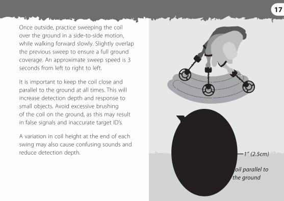
coil parallel to the ground
Once outside, practice sweeping the coil over the ground in a side‑to‑side motion, while walking forward slowly. Slightly overlap the previous sweep to ensure a full ground coverage. An approximate sweep speed is 3 seconds from left to right to left.
It is important to keep the coil close and parallel to the ground at all times. This will increase detection depth and response to small objects. Avoid excessive brushing of the coil on the ground, as this may result in false signals and inaccurate target ID’s.
A variation in coil height at the end of each swing may also cause confusing sounds and reduce detection depth. 1” (2.5cm)
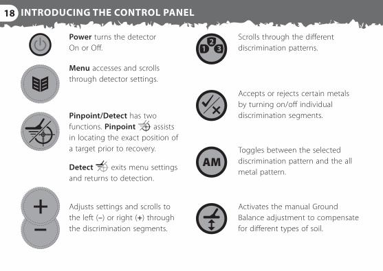
18 INTRODUCING THE CONTROL PANEL
Power turns the detector On or Off.
Scrolls through the different discrimination patterns.
Menu accesses and scrolls through detector settings.
Pinpoint/Detect has two functions. Pinpoint assists in locating the exact position of a target prior to recovery.
Detect exits menu settings and returns to detection.
Adjusts settings and scrolls to the left (–) or right (+) through the discrimination segments.
Accepts or rejects certain metals by turning on/off individual discrimination segments.
Toggles between the selected discrimination pattern and the all metal pattern.
Activates the manual Ground Balance adjustment to compensate for different types of soil.
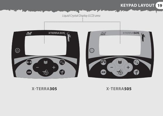
19KEYPAD LAYOUT
Liquid Crystal Display (LCD) area
X‑TERRA305 X‑TERRA505
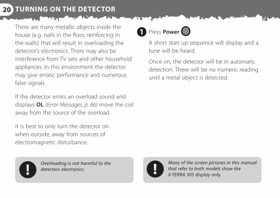
20 TURNING ON THE DETECTOR
There are many metallic objects inside the house (e.g. nails in the floor, reinforcing in the walls) that will result in overloading the detector’s electronics. There may also be interference from TV sets and other household appliances. In this environment the detector may give erratic performance and numerous false signals.
If the detector emits an overload sound and displays OL (Error Messages, p. 66) move the coil away from the source of the overload.
It is best to only turn the detector on when outside, away from sources of electromagnetic disturbance.
Press Power
A short start up sequence will display and a tune will be heard.
Once on, the detector will be in automatic detection. There will be no numeric reading until a metal object is detected.
Overloading is not harmful to the detectors electronics.
Many of the screen pictures in this manual that refer to both models show the X‑TERRA 505 display only.
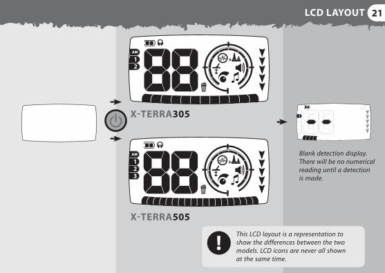
21LCD LAYOUT
12345AL
This LCD layout is a representation to show the differences between the two models. LCD icons are never all shown at the same time.
Blank detection display. There will be no numerical reading until a detection is made.
X‑TERRA305
X‑TERRA505
22 A SIMPLE DETECTING EXERCISE
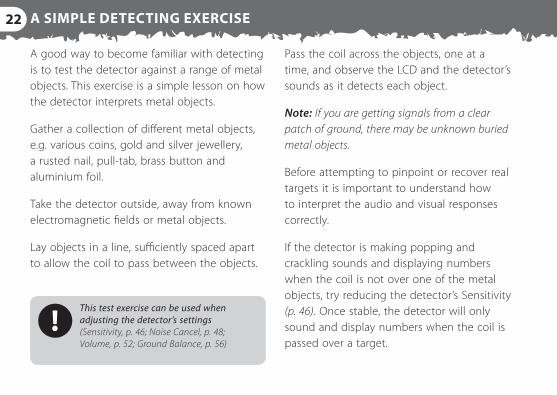
Pass the coil across the objects, one at a time, and observe the LCD and the detector’s sounds as it detects each object.
Note: If you are getting signals from a clear patch of ground, there may be unknown buried metal objects.
Before attempting to pinpoint or recover real targets it is important to understand how to interpret the audio and visual responses correctly.
If the detector is making popping and crackling sounds and displaying numbers when the coil is not over one of the metal objects, try reducing the detector’s Sensitivity (p. 46). Once stable, the detector will only sound and display numbers when the coil is passed over a target.
A good way to become familiar with detecting is to test the detector against a range of metal objects. This exercise is a simple lesson on how the detector interprets metal objects.
Gather a collection of different metal objects, e.g. various coins, gold and silver jewellery, a rusted nail, pull‑tab, brass button and aluminium foil.
Take the detector outside, away from known electromagnetic fields or metal objects.
Lay objects in a line, sufficiently spaced apart to allow the coil to pass between the objects.
This test exercise can be used when adjusting the detector’s settings (Sensitivity, p. 46; Noise Cancel, p. 48; Volume, p. 52; Ground Balance, p. 56)
23
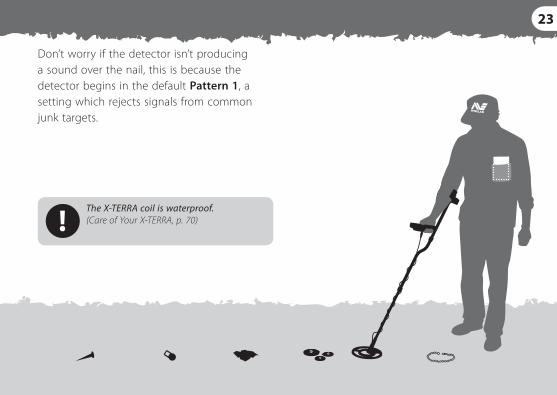
Don’t worry if the detector isn’t producing a sound over the nail, this is because the detector begins in the default Pattern 1, a setting which rejects signals from common junk targets.
The X‑TERRA coil is waterproof. (Care of Your X‑TERRA, p. 70)

24 EXAMPLE DETECTIONS
Discrimination Pattern The factory preset pattern 1 rejects ferrous metals and foil, and accepts nonferrous metals. Patterns can be edited and saved according to detecting preferences.
Audio A detected nonferrous target will give a medium – high tone audio response.
Visual A detected nonferrous target will give a visual indication within the nonferrous section of the discrimination scale and a positive target ID.
A detected target ID segment (indicated on the diagram by a grey icon) will flash (if accepted) quickly 3 times to show its position on the discrimination scale — just like a cursor on a computer screen. The segment will continue to flash slowly until another target ID segment is detected.
4 icons to indicate the targets depth from the coil, approx. 6‑8” (15‑20cm)Nonferrous coin
Medium High

25
1 icon to indicate the targets depth from the coil, approx. 0‑2” (0‑5cm)Ferrous nail
All Metal Pattern The all metal pattern turns off every discrimination segment, allowing all metals including ferrous targets to be detected.
Audio A detected ferrous target will give a low tone audio response.
Visual A detected ferrous target will give a visual indication within the ferrous section of the discrimination scale and a negative target ID.
Further understanding of detector basics and detailed detector operation may be obtained from the rest of this manual.
Low
26 HOW DETECTORS WORK
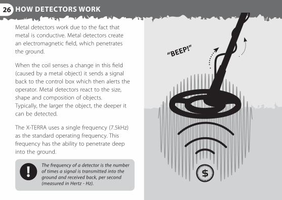
Metal detectors work due to the fact that metal is conductive. Metal detectors create an electromagnetic field, which penetrates the ground.
When the coil senses a change in this field (caused by a metal object) it sends a signal back to the control box which then alerts the operator. Metal detectors react to the size, shape and composition of objects. Typically, the larger the object, the deeper it can be detected.
The X‑TERRA uses a single frequency (7.5kHz) as the standard operating frequency. This frequency has the ability to penetrate deep into the ground.
The frequency of a detector is the number of times a signal is transmitted into the ground and received back, per second (measured in Hertz ‑ Hz).
“BEEP!”
27TARGET ID
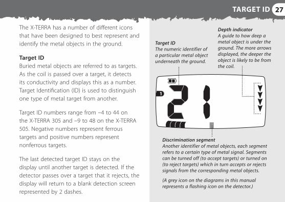
The X‑TERRA has a number of different icons that have been designed to best represent and identify the metal objects in the ground.
Target ID Buried metal objects are referred to as targets. As the coil is passed over a target, it detects its conductivity and displays this as a number. Target Identification (ID) is used to distinguish one type of metal target from another.
Target ID numbers range from –4 to 44 on the X‑TERRA 305 and –9 to 48 on the X‑TERRA 505. Negative numbers represent ferrous targets and positive numbers represent nonferrous targets.
The last detected target ID stays on the display until another target is detected. If the detector passes over a target that it rejects, the display will return to a blank detection screen represented by 2 dashes.
Discrimination segment Another identifier of metal objects, each segment refers to a certain type of metal signal. Segments can be turned off (to accept targets) or turned on (to reject targets) which in turn accepts or rejects signals from the corresponding metal objects.
(A grey icon on the diagrams in this manual represents a flashing icon on the detector.)
Target ID The numeric identifier of a particular metal object underneath the ground.
Depth indicator A guide to how deep a metal object is under the ground. The more arrows displayed, the deeper the object is likely to be from the coil.
28 DISCRIMINATION SCALE
12
12345AL
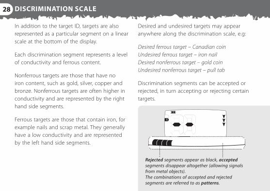
Rejected segments appear as black, accepted segments disappear altogether (allowing signals from metal objects). The combinations of accepted and rejected segments are referred to as patterns.
Desired and undesired targets may appear anywhere along the discrimination scale, e.g:
Desired ferrous target – Canadian coin Undesired ferrous target – iron nail Desired nonferrous target – gold coin Undesired nonferrous target – pull tab
Discrimination segments can be accepted or rejected, in turn accepting or rejecting certain targets.
In addition to the target ID, targets are also represented as a particular segment on a linear scale at the bottom of the display.
Each discrimination segment represents a level of conductivity and ferrous content.
Nonferrous targets are those that have no iron content, such as gold, silver, copper and bronze. Nonferrous targets are often higher in conductivity and are represented by the right hand side segments.
Ferrous targets are those that contain iron, for example nails and scrap metal. They generally have a low conductivity and are represented by the left hand side segments.
29
16 nonferrous3 ferrous
11 nonferrous1 ferrous
5AL
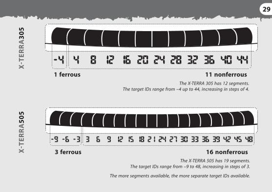
The X‑TERRA 305 has 12 segments. The target IDs range from –4 up to 44, increasing in steps of 4.
The X‑TERRA 505 has 19 segments. The target IDs range from –9 to 48, increasing in steps of 3.
The more segments available, the more separate target IDs available.
X‑T
ERR
A30
5X
‑TER
RA
505
30 PRESET DISCRIMINATION PATTERNS
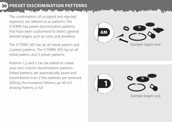
The combinations of accepted and rejected segments are referred to as patterns. The X‑TERRA has preset discrimination patterns that have been customised to detect general desired targets such as coins and jewellery.
The X‑TERRA 305 has an all metal pattern and 2 preset patterns. The X‑TERRA 505 has an all metal pattern and 3 preset patterns.
Patterns 1,2 and 3 can be edited to create your own custom discrimination patterns. Edited patterns are automatically saved and remembered even if the batteries are removed. (Editing Discrimination Patterns, pp. 60–61) (Erasing Patterns, p. 62)
12345AL
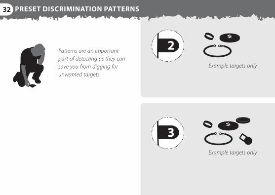
Example targets only
Example targets only
31
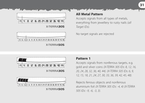
Pattern 1 Accepts signals from nonferrous targets, e.g. gold and silver coins (X‑TERRA 305 IDs: 8, 12, 16, 20, 24, 28, 32, 36, 40, 44). (X‑TERRA 505 IDs: 6, 9, 12, 15, 18, 21, 24, 27, 30, 33, 36, 39, 42, 45, 48).
Rejects ferrous objects and nonferrous aluminium foil (X‑TERRA 305 IDs: ‑4, 4) (X‑TERRA 505 IDs: ‑9, ‑6, ‑3, 3).
All Metal Pattern Accepts signals from all types of metals, everything from jewellery to rusty nails (all Target IDs).
No target signals are rejected
5AL
12345AL
32 PRESET DISCRIMINATION PATTERNS
Example targets only
Example targets only
Patterns are an important part of detecting as they can save you from digging for unwanted targets.
33
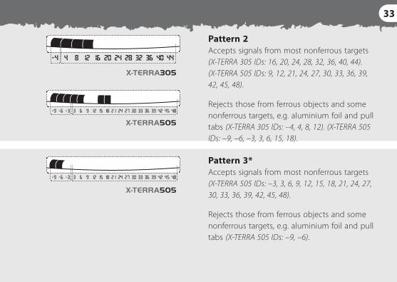
Pattern 2 Accepts signals from most nonferrous targets (X‑TERRA 305 IDs: 16, 20, 24, 28, 32, 36, 40, 44). (X‑TERRA 505 IDs: 9, 12, 21, 24, 27, 30, 33, 36, 39, 42, 45, 48).
Rejects those from ferrous objects and some nonferrous targets, e.g. aluminium foil and pull tabs (X‑TERRA 305 IDs: –4, 4, 8, 12). (X‑TERRA 505 IDs: –9, –6, –3, 3, 6, 15, 18).
Pattern 3* Accepts signals from most nonferrous targets (X‑TERRA 505 IDs: –3, 3, 6, 9, 12, 15, 18, 21, 24, 27, 30, 33, 36, 39, 42, 45, 48).
Rejects those from ferrous objects and some nonferrous targets, e.g. aluminium foil and pull tabs (X‑TERRA 505 IDs: –9, –6).
34 CHOOSING A DISCRIMINATION PATTERN – X‑TERRA 305
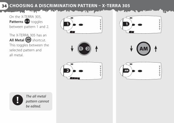
On the X‑TERRA 305, Patterns toggles between pattern 1 and 2.
The X‑TERRA 305 has an All Metal shortcut. This toggles between the selected pattern and all metal.
The all metal pattern cannot be edited.
35CHOOSING A DISCRIMINATION PATTERN – X‑TERRA 505
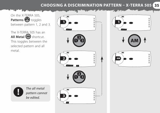
On the X‑TERRA 505, Patterns toggles between pattern 1, 2 and 3.
The X‑TERRA 505 has an All Metal shortcut. This toggles between the selected pattern and all metal.
The all metal pattern cannot be edited.
36 PINPOINTING
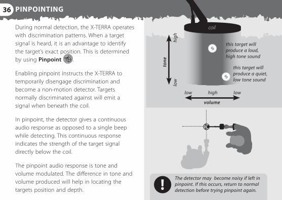
During normal detection, the X‑TERRA operates with discrimination patterns. When a target signal is heard, it is an advantage to identify the target’s exact position. This is determined by using Pinpoint .
Enabling pinpoint instructs the X‑TERRA to temporarily disengage discrimination and become a non‑motion detector. Targets normally discriminated against will emit a signal when beneath the coil.
In pinpoint, the detector gives a continuous audio response as opposed to a single beep while detecting. This continuous response indicates the strength of the target signal directly below the coil.
The pinpoint audio response is tone and volume modulated. The difference in tone and volume produced will help in locating the targets position and depth.
low high
high
lo
w
low
tone
volume
coil
this target will produce a loud, high tone sound
this target will produce a quiet, low tone sound
The detector may become noisy if left in pinpoint. If this occurs, return to normal detection before trying pinpoint again.
37
12345AL
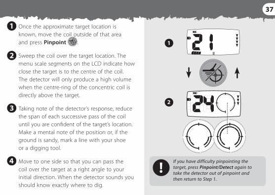
Once the approximate target location is known, move the coil outside of that area and press Pinpoint .
Sweep the coil over the target location. The menu scale segments on the LCD indicate how close the target is to the centre of the coil. The detector will only produce a high volume when the centre‑ring of the concentric coil is directly above the target.
Taking note of the detector’s response, reduce the span of each successive pass of the coil until you are confident of the target’s location. Make a mental note of the position or, if the ground is sandy, mark a line with your shoe or a digging tool.
Move to one side so that you can pass the coil over the target at a right angle to your initial direction. When the detector sounds you should know exactly where to dig.
If you have difficulty pinpointing the target, press Pinpoint/Detect again to take the detector out of pinpoint and then return to Step 1.
38 RECOVERING THE TARGET
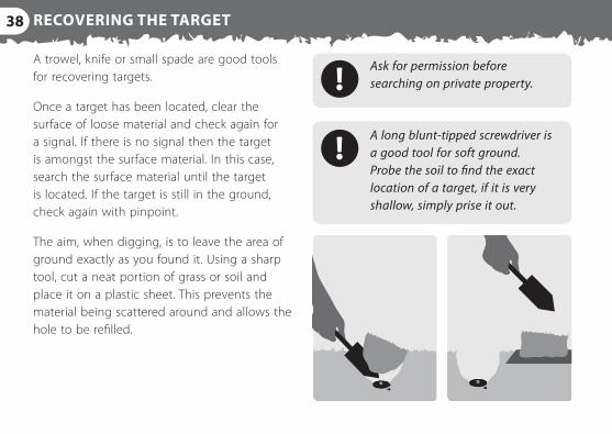
A trowel, knife or small spade are good tools for recovering targets.
Once a target has been located, clear the surface of loose material and check again for a signal. If there is no signal then the target is amongst the surface material. In this case, search the surface material until the target is located. If the target is still in the ground, check again with pinpoint.
The aim, when digging, is to leave the area of ground exactly as you found it. Using a sharp tool, cut a neat portion of grass or soil and place it on a plastic sheet. This prevents the material being scattered around and allows the hole to be refilled.
A long blunt‑tipped screwdriver is a good tool for soft ground. Probe the soil to find the exact location of a target, if it is very shallow, simply prise it out.
Ask for permission before searching on private property.
39
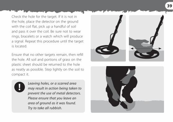
Check the hole for the target. If it is not in the hole, place the detector on the ground with the coil flat, pick up a handful of soil and pass it over the coil. Be sure not to wear rings, bracelets or a watch which will produce a signal. Repeat this procedure until the target is located.
Ensure that no other targets remain, then refill the hole. All soil and portions of grass on the plastic sheet should be returned to the hole as neatly as possible. Step lightly on the soil to compact it.
Leaving holes, or a scarred area may result in action being taken to prevent the use of metal detectors. Please ensure that you leave an area of ground as it was found. Try to take all rubbish.
40 LCD ICONS
12
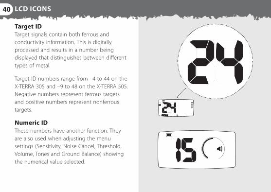
Target ID Target signals contain both ferrous and conductivity information. This is digitally processed and results in a number being displayed that distinguishes between different types of metal.
Target ID numbers range from –4 to 44 on the X‑TERRA 305 and –9 to 48 on the X‑TERRA 505. Negative numbers represent ferrous targets and positive numbers represent nonferrous targets.
Numeric ID These numbers have another function. They are also used when adjusting the menu settings (Sensitivity, Noise Cancel, Threshold, Volume, Tones and Ground Balance) showing the numerical value selected.
41
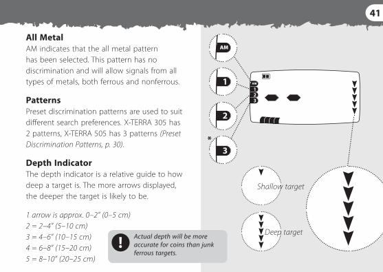
All Metal AM indicates that the all metal pattern has been selected. This pattern has no discrimination and will allow signals from all types of metals, both ferrous and nonferrous.
Patterns Preset discrimination patterns are used to suit different search preferences. X‑TERRA 305 has 2 patterns, X‑TERRA 505 has 3 patterns (Preset Discrimination Patterns, p. 30).
Depth Indicator The depth indicator is a relative guide to how deep a target is. The more arrows displayed, the deeper the target is likely to be.
1 arrow is approx. 0–2” (0–5 cm) 2 = 2–4” (5–10 cm) 3 = 4–6” (10–15 cm) 4 = 6–8” (15–20 cm) 5 = 8–10” (20–25 cm)
*
Shallow target
Deep targetActual depth will be more accurate for coins than junk ferrous targets.
42 LCD ICONS
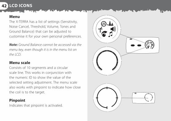
Menu The X‑TERRA has a list of settings (Sensitivity, Noise Cancel, Threshold, Volume, Tones and Ground Balance) that can be adjusted to customise it for your own personal preferences.
Note: Ground Balance cannot be accessed via the menu key, even though it is in the menu list on the LCD.
Menu scale Consists of 10 segments and a circular scale line. This works in conjunction with the numeric ID to show the value of the selected setting adjustment. The menu scale also works with pinpoint to indicate how close the coil is to the target.
Pinpoint Indicates that pinpoint is activated.
43
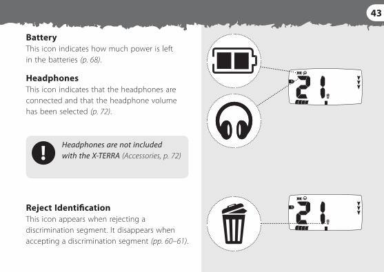
Headphones are not included with the X‑TERRA (Accessories, p. 72)
Battery This icon indicates how much power is left in the batteries (p. 68).
Headphones This icon indicates that the headphones are connected and that the headphone volume has been selected (p. 72).
Reject Identification This icon appears when rejecting a discrimination segment. It disappears when accepting a discrimination segment (pp. 60–61).
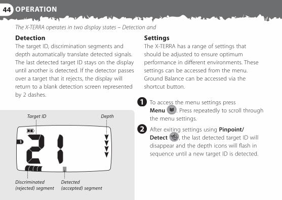
44 OPERATION
Target ID
Discriminated (rejected) segment
Depth
Detected (accepted) segment
Detection The target ID, discrimination segments and depth automatically translate detected signals. The last detected target ID stays on the display until another is detected. If the detector passes over a target that it rejects, the display will return to a blank detection screen represented by 2 dashes.
To access the menu settings press Menu . Press repeatedly to scroll through the menu settings.
After exiting settings using Pinpoint/Detect , the last detected target ID will disappear and the depth icons will flash in sequence until a new target ID is detected.
Settings The X‑TERRA has a range of settings that should be adjusted to ensure optimum performance in different environments. These settings can be accessed from the menu. Ground Balance can be accessed via the shortcut button.
The X‑TERRA operates in two display states – Detection and
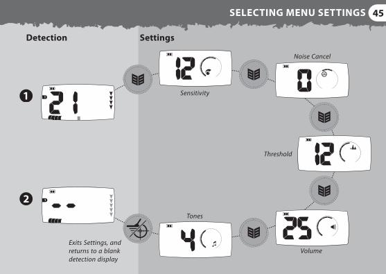
45SELECTING MENU SETTINGS
Exits Settings, and returns to a blank detection display
Detection Settings
Sensitivity
Noise Cancel
Threshold
Tones
Volume
46 SENSITIVITY
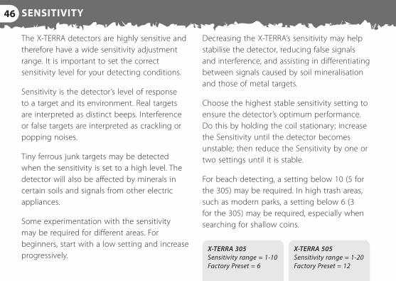
The X‑TERRA detectors are highly sensitive and therefore have a wide sensitivity adjustment range. It is important to set the correct sensitivity level for your detecting conditions.
Sensitivity is the detector’s level of response to a target and its environment. Real targets are interpreted as distinct beeps. Interference or false targets are interpreted as crackling or popping noises.
Tiny ferrous junk targets may be detected when the sensitivity is set to a high level. The detector will also be affected by minerals in certain soils and signals from other electric appliances.
Some experimentation with the sensitivity may be required for different areas. For beginners, start with a low setting and increase progressively.
Decreasing the X‑TERRA’s sensitivity may help stabilise the detector, reducing false signals and interference, and assisting in differentiating between signals caused by soil mineralisation and those of metal targets.
Choose the highest stable sensitivity setting to ensure the detector’s optimum performance. Do this by holding the coil stationary; increase the Sensitivity until the detector becomes unstable; then reduce the Sensitivity by one or two settings until it is stable.
For beach detecting, a setting below 10 (5 for the 305) may be required. In high trash areas, such as modern parks, a setting below 6 (3 for the 305) may be required, especially when searching for shallow coins.
X‑TERRA 305 Sensitivity range = 1‑10 Factory Preset = 6
X‑TERRA 505 Sensitivity range = 1‑20 Factory Preset = 12
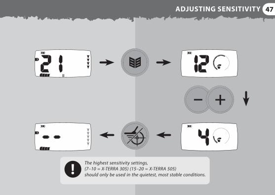
47ADJUSTING SENSITIVITY
The highest sensitivity settings, (7–10 = X‑TERRA 305) (15–20 = X‑TERRA 505) should only be used in the quietest, most stable conditions.
48 NOISE CANCEL
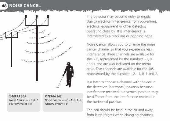
The detector may become noisy or erratic due to electrical interference from powerlines, electrical equipment or other detectors operating close by. This interference is interpreted as a crackling or popping noise.
Noise Cancel allows you to change the noise cancel channel so that you experience less interference. Three channels are available for the 305, represented by the numbers –1, 0 and 1 and are also indicated on the menu scale. Five channels are available for the 505, represented by the numbers –2, –1, 0, 1 and 2.
It is best to choose a channel with the coil in the detection (horizontal) position because interference received in a vertical position may be different from the interference received in the horizontal position.
The coil should be held in the air and away from large targets when changing channels.
X‑TERRA 305 Noise Cancel = –1, 0, 1 Factory Preset = 0
X‑TERRA 505 Noise Cancel = –2, –1, 0, 1, 2 Factory Preset = 0
49
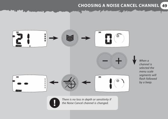
There is no loss in depth or sensitivity if the Noise Cancel channel is changed.
CHOOSING A NOISE CANCEL CHANNEL
When a channel is selected the menu scale segments will flash followed by a beep.
50 THRESHOLD
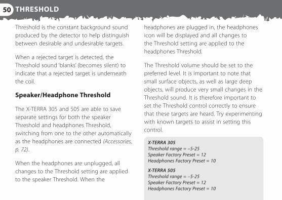
Threshold is the constant background sound produced by the detector to help distinguish between desirable and undesirable targets.
When a rejected target is detected, the Threshold sound ‘blanks’ (becomes silent) to indicate that a rejected target is underneath the coil.
Speaker/Headphone Threshold
The X‑TERRA 305 and 505 are able to save separate settings for both the speaker Threshold and headphones Threshold, switching from one to the other automatically as the headphones are connected (Accessories, p. 72).
When the headphones are unplugged, all changes to the Threshold setting are applied to the speaker Threshold. When the
headphones are plugged in, the headphones icon will be displayed and all changes to the Threshold setting are applied to the headphones Threshold.
The Threshold volume should be set to the preferred level. It is important to note that small surface objects, as well as large deep objects, will produce very small changes in the Threshold sound. It is therefore important to set the Threshold control correctly to ensure that these targets are heard. Try experimenting with known targets to assist in setting this control.
X‑TERRA 305 Threshold range = –5‑25 Speaker Factory Preset = 12 Headphones Factory Preset = 10
X‑TERRA 505 Threshold range = –5‑25 Speaker Factory Preset = 12 Headphones Factory Preset = 10
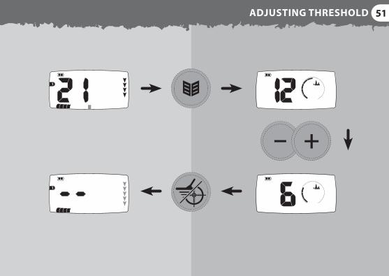
51ADJUSTING THRESHOLD
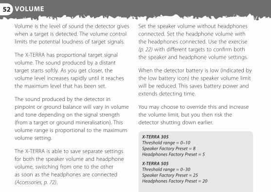
52 VOLUME
Volume is the level of sound the detector gives when a target is detected. The volume control limits the potential loudness of target signals.
The X‑TERRA has proportional target signal volume. The sound produced by a distant target starts softly. As you get closer, the volume level increases rapidly until it reaches the maximum level that has been set.
The sound produced by the detector in pinpoint or ground balance will vary in volume and tone depending on the signal strength (from a target or ground mineralisation). This volume range is proportional to the maximum volume setting.
The X‑TERRA is able to save separate settings for both the speaker volume and headphone volume, switching from one to the other as soon as the headphones are connected (Accessories, p. 72).
Set the speaker volume without headphones connected. Set the headphone volume with the headphones connected. Use the exercise (p. 22) with different targets to confirm both the speaker and headphone volume settings.
When the detector battery is low (indicated by the low battery icon) the speaker volume limit will be reduced. This saves battery power and extends detecting time.
You may choose to override this and increase the volume limit, but you then risk the detector shutting down earlier.
X‑TERRA 305 Threshold range = 0–10 Speaker Factory Preset = 8 Headphones Factory Preset = 5
X‑TERRA 505 Threshold range = 0–30 Speaker Factory Preset = 25 Headphones Factory Preset = 20
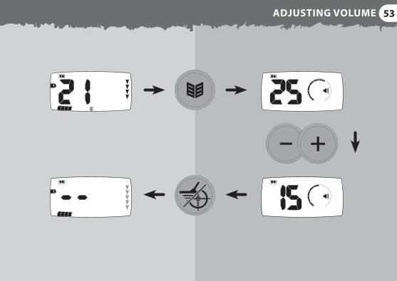
53ADJUSTING VOLUME
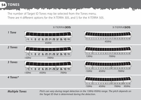
54 TONES
The number of Target ID Tones may be selected from the Tones menu. There are 4 different options for the X‑TERRA 305, and 5 for the X‑TERRA 505.
1 Tone
2 Tones
3 Tones
4 Tones*
Multiple Tones
450Hz
700Hz130Hz700Hz130Hz
700Hz
700Hz 950Hz
450Hz
450Hz
130Hz
130Hz
700Hz450Hz130Hz
450Hz
Pitch can vary during target detection in the 130Hz‑950Hz range. The pitch depends on the Target ID that is determined during the detection.
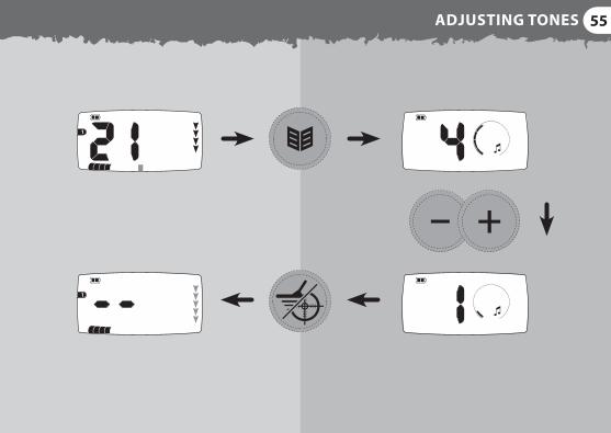
55ADJUSTING TONES
56 GROUND BALANCE
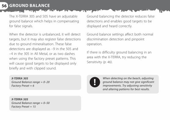
Ground balancing the detector reduces false detections and enables good targets to be displayed and heard correctly.
Ground balance settings affect both normal discrimination detection and pinpoint operation.
If there is difficulty ground balancing in an area with the X‑TERRA, try reducing the Sensitivity (p. 46).
The X‑TERRA 305 and 505 have an adjustable ground balance which helps in compensating for false signals.
When the detector is unbalanced, it will detect targets, but it may also register false detections due to ground mineralisation. These false detections are displayed as –9 in the 505 and –4 in the 305 in All Metal, or as two dashes when using the factory preset patterns. This will cause good targets to be displayed only briefly and with clipped sound.
When detecting on the beach, adjusting ground balance may not give significant improvements. Try adjusting sensitivity and altering patterns for best results.
X‑TERRA 305 Ground Balance range = 0–20 Factory Preset = 6
X‑TERRA 505 Ground Balance range = 0–50 Factory Preset = 15
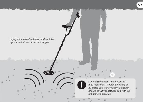
Highly mineralised soil may produce false signals and distract from real targets.
Mineralised ground and ‘hot rocks’ may register as –9 when detecting in all metal. This is more likely to happen at high sensitivity settings and with an unbalanced detector.
57
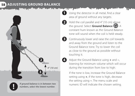
4” (10 cm)
If ground balance is in between two numbers, select the lowest number.
58 ADJUSTING GROUND BALANCE
Using the detector in all metal, find a clear area of ground without any targets.
Hold the coil parallel and 4” (10 cm) above the ground. Select Ground Balance . A constant hum known as the Ground Balance tone will sound when the coil is held steady.
Continuously lower and raise the coil towards and away from the ground and listen to the Ground Balance tone. Try to lower the coil as close to the ground as possible without touching it.
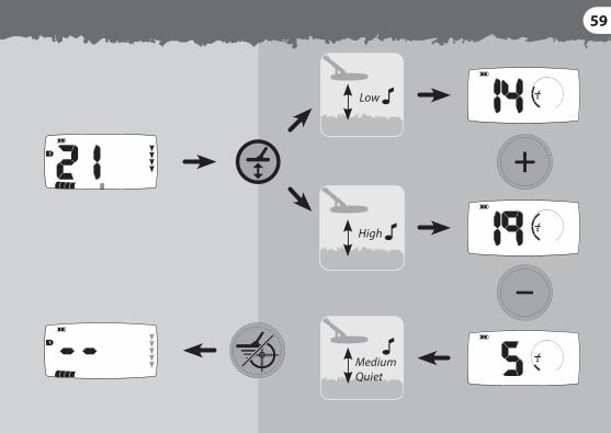
Adjust the Ground Balance using + and –, listening for minimum volume which will occur during the transition from low to high.
If the tone is low, increase the Ground Balance setting using +, if the tone is high, decrease the setting using –. The menu scale and numeric ID will indicate the chosen setting.
59
High
Low
Medium Quiet
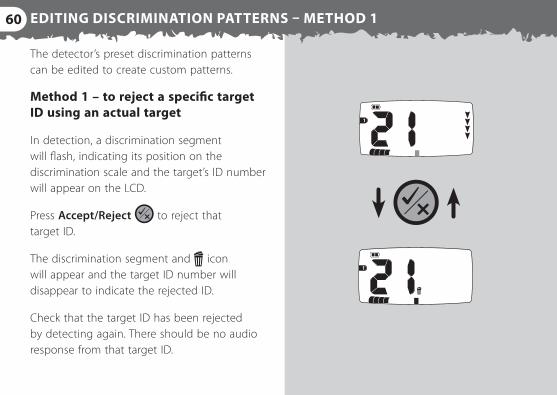
60 EDITING DISCRIMINATION PATTERNS – METHOD 1
The detector’s preset discrimination patterns can be edited to create custom patterns.
Method 1 – to reject a specific target ID using an actual target
In detection, a discrimination segment will flash, indicating its position on the discrimination scale and the target’s ID number will appear on the LCD.
Press Accept/Reject to reject that target ID.
The discrimination segment and icon will appear and the target ID number will disappear to indicate the rejected ID.
Check that the target ID has been rejected by detecting again. There should be no audio response from that target ID.
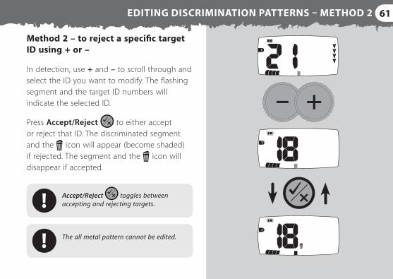
61EDITING DISCRIMINATION PATTERNS – METHOD 2
Method 2 – to reject a specific target ID using + or –
In detection, use + and – to scroll through and select the ID you want to modify. The flashing segment and the target ID numbers will indicate the selected ID.
Press Accept/Reject to either accept or reject that ID. The discriminated segment and the icon will appear (become shaded) if rejected. The segment and the icon will disappear if accepted.
Accept/Reject toggles between accepting and rejecting targets.
The all metal pattern cannot be edited.
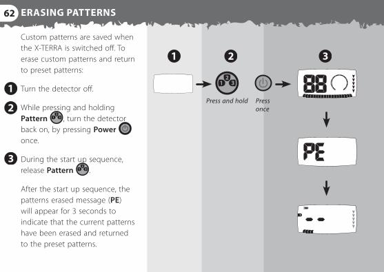
62 ERASING PATTERNS
Press and hold Press once
Custom patterns are saved when the X‑TERRA is switched off. To erase custom patterns and return to preset patterns:
Turn the detector off.
While pressing and holding Pattern , turn the detector back on, by pressing Power once.
During the start up sequence, release Pattern .
After the start up sequence, the patterns erased message (PE) will appear for 3 seconds to indicate that the current patterns have been erased and returned to the preset patterns.
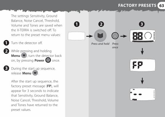
63FACTORY PRESETS
Press and hold Press once
The settings Sensitivity, Ground Balance, Noise Cancel, Threshold, Volume and Tones are saved when the X‑TERRA is switched off. To return to the preset menu values:
Turn the detector off.
While pressing and holding Menu , turn the detector back on, by pressing Power once.
During the start up sequence, release Menu .
After the start up sequence, the factory preset message (FP), will appear for 3 seconds to indicate that Sensitivity, Ground Balance, Noise Cancel, Threshold, Volume and Tones have returned to the preset values.
64 SOUNDS
Start Up Sequence When the detector is turned on, there is a short three note tune during its start up sequence.
Positive Acknowledgement The detector emits a short beep for every accepted key press.
Negative Acknowledgement The detector emits a low double beep to indicate an invalid keypress.
Patterns Erased / Factory Preset A six note tune will announce when these settings are complete.
Error A six note tune will sound to indicate a detector error (Error Messages, p. 66).
Overload If the coil is passed across a large shallow target, the detector will give a repeating buzzing sound. This indicates that the target signal is too strong for the detector to interpret.
Low Battery Signal When the battery power becomes low, there will be a short announcement tune (descending tones) every 60 seconds.
65
Low Battery Shutdown A long announcement tune (descending tones) will sound just before the detector shuts down.
Target Response This is the sound given by the detector when a target is located and not discriminated against (rejected). Generally a target that is highly conductive (e.g. a large silver coin) emits a high tone beep. A low tone beep is produced for ferrous targets.
Pinpoint Response When in pinpoint, the detector emits a variable tone, that increases in pitch and volume as the coil gets closer to the target.
Noise A random jittery sound indicates that the detector is picking up external interference. Sensitivity or Noise Cancel should be adjusted.
False Detections A partial or chopped non‑repeatable signal. Two dashes will indicate on the LCD to indicate a rejected target.
66 ERROR MESSAGES
1
1 12345AL
12345AL
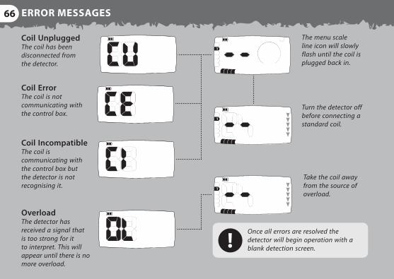
Coil Unplugged The coil has been disconnected from the detector.
Coil Error The coil is not communicating with the control box.
Coil Incompatible The coil is communicating with the control box but the detector is not recognising it.
1
1
12345AL
Overload The detector has received a signal that is too strong for it to interpret. This will appear until there is no more overload.
The menu scale line icon will slowly flash until the coil is plugged back in.
Turn the detector off before connecting a standard coil.
Take the coil away from the source of overload.
Once all errors are resolved the detector will begin operation with a blank detection screen.
67COIL IDENTIFICATION
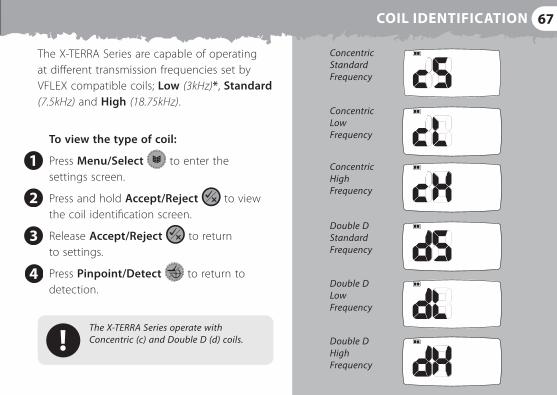
The X‑TERRA Series are capable of operating at different transmission frequencies set by VFLEX compatible coils; Low (3kHz)*, Standard (7.5kHz) and High (18.75kHz).
To view the type of coil:
Press Menu/Select to enter the settings screen.
Press and hold Accept/Reject to view the coil identification screen.
Release Accept/Reject to return to settings.
Press Pinpoint/Detect to return to detection.
The X‑TERRA Series operate with Concentric (c) and Double D (d) coils.
Concentric Standard Frequency
Concentric Low Frequency
Concentric High Frequency
Double D Standard Frequency
Double D Low Frequency
Double D High Frequency
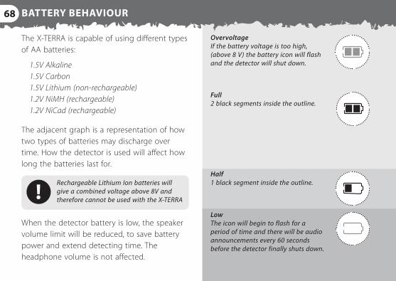
Overvoltage If the battery voltage is too high, (above 8 V) the battery icon will flash and the detector will shut down.
Full 2 black segments inside the outline.
Half 1 black segment inside the outline.
Low The icon will begin to flash for a period of time and there will be audio announcements every 60 seconds before the detector finally shuts down.
68 BATTERY BEHAVIOUR
The X‑TERRA is capable of using different types of AA batteries:
1.5V Alkaline 1.5V Carbon 1.5V Lithium (non‑rechargeable) 1.2V NiMH (rechargeable) 1.2V NiCad (rechargeable)
The adjacent graph is a representation of how two types of batteries may discharge over time. How the detector is used will affect how long the batteries last for.
Rechargeable Lithium Ion batteries will give a combined voltage above 8V and therefore cannot be used with the X‑TERRA
When the detector battery is low, the speaker volume limit will be reduced, to save battery power and extend detecting time. The headphone volume is not affected.
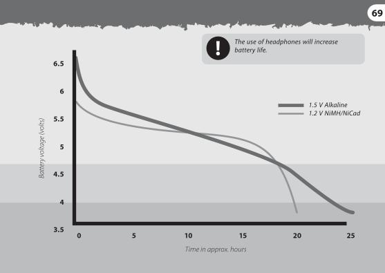
1.5 V Alkaline 1.2 V NiMH/NiCad
69
The use of headphones will increase battery life.

70 CARE OF YOUR X‑TERRA
The X‑TERRA is a high quality electronic instrument, finely engineered and packaged in a durable housing. Taking proper care of your X‑TERRA is common sense.
The X‑TERRA’s storage temperature is –4˚F to 149˚F (–20˚C to +65˚C) and the operating temperature is 32˚F to 113˚F (0˚C to 45˚C). Do not leave the detector in excessive heat or cold for longer than necessary. Try to avoid leaving it in a closed trunk or in a car sitting in sunlight. Covering it when not in use will help protect it.
The coil can be submersed in water up to 20” (0.5m), yet the control box is not waterproof. Although it has been designed to be weather resistant, it is advised to protect the control box in wet conditions. A protective control box cover is available. (Accessories, p. 72)
Never allow the detector to come into contact with gasoline or other petroleum based liquids.
Keep the detector clean and dry and avoid getting sand and grit into the shafts or fastenings (e.g. yoke, twistlocks). Do not use solvents to clean the detector. Use a damp cloth with mild soap detergent.
71
The display window may be prone to scratching or damage if not treated with care. A protective control box cover is available. (Accessories, p. 73)
Ensure the coil cable is in good condition and not subject to undue stress (particularly where it is connected to the coil).
Always remember to turn off the detector before changing coils.
Coils from other models of Minelab detectors will not function with the X‑TERRA Series (Accessories, p. 73). Only VFLEX compatible coils will operate correctly with the X‑TERRA Series.
Old, flat or faulty batteries may cause many detector problems, through electrolyte leakage. Take the batteries out if the detector will not be used for long periods of time (e.g. more than 1 week). Ensure that only good quality batteries are used and that they are replaced when the low battery signal sounds.
Do not use rechargeable Lithium Ion batteries as their voltage is too high. Non‑rechargeable Lithium batteries may be used.
72 ACCESSORIES
Headphones have many advantages. They block out external noise such as wind and traffic, allowing you to listen more closely to target signals. Headphones also minimise disturbance to other people in the area and they extend battery life.
The X‑TERRA is able to save separate settings for both the speaker volume and headphone volume, switching from one to the other as soon as the headphones are connected. (Volume, p. 52)
Ensure that the headphone volume does not reach an extremely loud level. This may increase the risk of hearing damage.
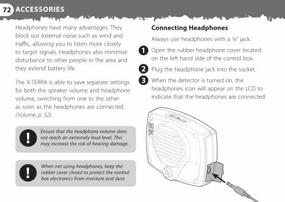
Connecting Headphones
Always use headphones with a ¼“ jack.
Open the rubber headphone cover located on the left hand side of the control box.
Plug the headphone jack into the socket.
When the detector is turned on, the headphones icon will appear on the LCD to indicate that the headphones are connected.
When not using headphones, keep the rubber cover closed to protect the control box electronics from moisture and dust.
73
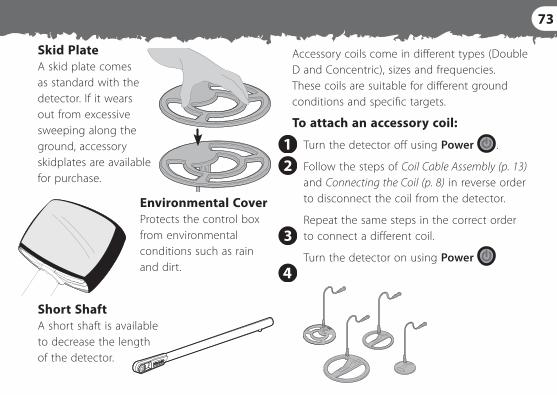
Skid Plate A skid plate comes as standard with the detector. If it wears out from excessive sweeping along the ground, accessory skidplates are available for purchase.
Environmental Cover Protects the control box from environmental conditions such as rain and dirt.
Accessory coils come in different types (Double D and Concentric), sizes and frequencies. These coils are suitable for different ground conditions and specific targets.
To attach an accessory coil:
Turn the detector off using Power .
Follow the steps of Coil Cable Assembly (p. 13) and Connecting the Coil (p. 8) in reverse order to disconnect the coil from the detector.
Repeat the same steps in the correct order to connect a different coil.
Turn the detector on using Power
Short Shaft A short shaft is available to decrease the length of the detector.
74
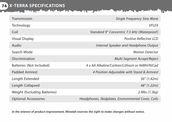
Transmission
Technology
Coil
Visual Display
Audio
Search Mode
Discrimination
Batteries (Not Included)
Padded Armrest
Length Extended
Length Collapsed
Weight (Excluding Batteries)
Optional Accessories
Single Frequency Sine Wave
VFLEX
Standard 9” Concentric 7.5 kHz (Waterproof )
Positive Reflective LCD
Internal Speaker and Headphone Output
Motion Detector
Multi Segment Accept/Reject
4 x AA Alkaline/Carbon/Lithium or NiMH/NiCad
4 Position Adjustable with Stand & Armrest
56” (1.42m)
48” (1.22m)
2.9lbs (1.3kg)
Headphones, Skidplates, Environmental Cover, Coils
In the interest of product improvement, Minelab reserves the right to make changes without notice.
X‑TERRA SPECIFICATIONS
75
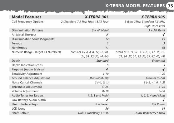
X‑TERRA 505 3 (Low 3kHz, Standard 7.5 kHz,
High 18.75 kHz) 3 + All Metal
19
3 16
Steps of 3 (‑9, ‑6, ‑3, 3, 6, 9, 12, 15, 18, 21, 24, 27, 30, 33, 36, 39, 42, 45, 48)
Enhanced 5
1‑20 Manual (0–50)
5 (–2, –1, 0, 1, 2) –5–25
0–30 1, 2, 3, 4 and Multi
8 + Power
64 Dulux Wineberry 51046
Model Features Coil Frequency Options Discrimination Patterns All Metal Shortcut Discrimination Scale (Segments) Ferrous Nonferrous Numeric Range (Target ID Numbers) Depth Depth Indication Icons Pinpoint (Audio & Visual) Sensitivity Adjustment Ground Balance Adjustment Noise Cancel Channels Threshold Adjustment Volume Adjustment Audio Tones for Targets Low Battery Audio Alarm User Interface Keys LCD Icons Shaft Colour
X‑TERRA 305 2 (Standard 7.5 kHz, High 18.75 kHz)
2 + All Metal
12
1 11
Steps of 4 (‑4, 4, 8, 12, 16, 20, 24, 28, 32, 36, 40, 44)
Standard 5
1‑10 Manual (0–20)
3 (–1, 0, 1) –5–25
0–10 1, 2, 3 and Multi
8 + Power
56 Dulux Wineberry 51046
X‑TERRA MODEL FEATURES
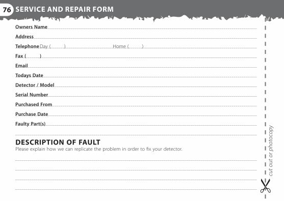
76 SERVICE AND REPAIR FORM
Owners Name
Address
Telephone Day ( ) Home ( )
Fax ( )
Todays Date
Detector / Model
Serial Number
Purchased From
Purchase Date
Faulty Part(s)
DESCRIPTION OF FAULTPlease explain how we can replicate the problem in order to fix your detector.
cut o
ut o
r pho
toco
py

THIS DEVICE COMPLIES WITH PART 15 OF THE FCC RULESOperation is subject to the following two conditions: (1) this device may not cause harmful interference, and (2) this device must accept any interference received, including interference that may cause undesired operation.
Disclaimer: The Minelab metal detector discussed in this instruction manual has been expressly designed and manufactured as a quality hobbyist metal detector and is recommended for use in coin, treasure and general metal detection in nonhazardous environments. This metal detector has not been designed for use as a mine detector or as a live munitions detection tool.
Working for a Cleaner, Greener FutureFor Consumers within the European Union: Do not dispose of this equipment in general household waste.
The crossed wheeled bin symbol on this equipment indicates this unit should not be disposed of in general household waste, but recycled in compliance with local government regulations and environmental requirements.
Please dispose of this equipment via a recycling service or centre, or by returning the unit to the respective Minelab outlet as appropriate for your unit. This will enable the equipment to be disposed of in an environmentally safe manner.
Disposal of unwanted electronic equipment in land filled waste may contribute to adverse long term environmental effect due to the leaching of contaminating and toxic substances contained within some electronic equipment.
World Leader in Metal Sensing Technology
From our origins in 1985, Minelab have specialised in advanced
electronic technologies. Our competitive advantage was created
almost immediately with a highly competent and innovative
Research and Development team, inspired by the genius of Mr
Bruce Candy.
This commitment to innovation has enabled us to successfully
market feature-packed Consumer coin and treasure detectors
enjoyed by hobbyists worldwide as well as high quality gold
detectors used by both professionals and amateurs. Minelab’s
advanced technology is also incorporated into detection
equipment designed for military and humanitarian de-mining
projects throughout the world.
Today Minelab has manufacturing, distribution and customer
service operations in Australia, Europe and the United States, and
is an ISO 9001 Quality Endorsed Company. ISO 9001 is a worldwide
quality standard certification that ensures the highest level of
product quality for our customers.
Please note: Since there may be a variety of options available for this detector, equipment may vary according to the Model or items ordered with your detector. Certain descriptions and illustrations may also differ (in this manual) from the exact Model that you purchased. In addition, Minelab reserves the right to respond to ongoing technical progress by introducing changes in design, equipment and technical features at any time.
Part Number: 4901-0071-4
© 2016 Minelab Electronics Pty Ltd
This document contains proprietary information which is protected by copyright. Apart from any use as permitted under the Copyright Act 1968, no part may be reproduced by any process without written permission from Minelab Electronics Pty Ltd, 2 Second Ave, Mawson Lakes, SA 5095, Australia.
WARNING. This document contains Minelab Electronics Pty Ltd rights, technical data or restricted rights data, or both. Patents and trademarks apply. Serious Detecting and Minelab are all trademarks of Minelab Electronics Pty Ltd.
US Patent No: 7432715. AU Patent No: 2005276953.
For further product information and detecting tips, refer to:
www.minelab.com
Numerical Target ID
Discrimination Patterns
Discrimination Scale
Depth Gauge
Battery Indicates remaining power.
Headphones Indicates headphones are connected.
Reject Identification Appears when you reject a discrimination segment.
Sensitivity Indicates that you are in the Sensitivity menu.
Ground Balance Indicates that you are in the Ground Balance menu.
Noise Cancel Indicates that you are in the Noise Cancel menu.
Threshold Indicates that you are in the Threshold menu.
Volume Indicates that you are in the Volume menu.
Tones Indicates that you are in the Tones menu.
Minelab Electronics Pty Ltd
Tel: +61 (0)8 8238 0888
Email: [email protected]
Minelab International Ltd
Tel: +353 (0)21 423 2352
Email: [email protected]
Minelab MEA General Trading LLC
Tel: +971 4 254 9995
Email: [email protected]
Minelab Americas Inc
Tel: +1 630 401 8150
Email: [email protected]