field guide to shareable clinical pathways - trisotech.com · 2 | guide to shareable clinical...
TRANSCRIPT
1 | Guide to Shareable Clinical Pathways - 1805211
Field Guide to Shareable Clinical Pathways
BPMN, CMMN & DMN in Healthcare
Version: 1.0
OMG Healthcare Domain Taskforce [email protected]
This paper presents a discussion of technology issues considered in a Subgroup of the Object Management Group. The contents of this paper are presented to foster wider
discussion on this topic; the content of this paper is not an adopted standard of any kind. This paper does not represent the official position of the Object Management Group.
2 | Guide to Shareable Clinical Pathways - 1805211
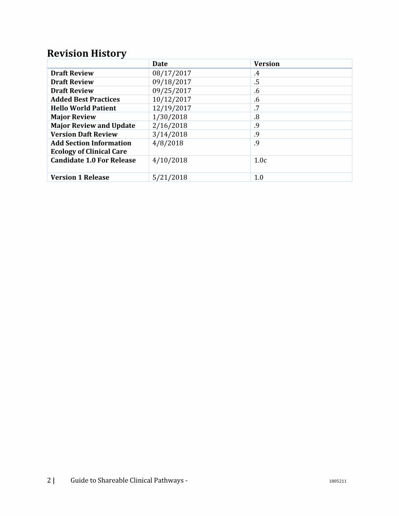
Revision History Date Version
Draft Review 08/17/2017 .4 Draft Review 09/18/2017 .5 Draft Review 09/25/2017 .6 Added Best Practices 10/12/2017 .6 Hello World Patient 12/19/2017 .7 Major Review 1/30/2018 .8 Major Review and Update 2/16/2018 .9 Version Daft Review 3/14/2018 .9 Add Section Information Ecology of Clinical Care
4/8/2018 .9
Candidate 1.0 For Release
4/10/2018 1.0c
Version 1 Release 5/21/2018 1.0
3 | Guide to Shareable Clinical Pathways - 1805211
LICENSES
The companies listed above have granted to the Object Management Group, Inc. (OMG) a nonexclusive, royalty-
free, paid up, worldwide license to copy and distribute this document and to modify this document and distribute
copies of the modified version. Each of the copyright holders listed above has agreed that no person shall be deemed
to have infringed the copyright in the included material of any such copyright holder by reason of having used the
specification set forth herein or having conformed any computer software to the specification.
Subject to all of the terms and conditions below, the owners of the copyright in this specification hereby grant you a
fully-paid up, non-exclusive, nontransferable, perpetual, worldwide license (without the right to sublicense), to use
this specification to create and distribute software and special purpose specifications that are based upon this
specification, and to use, copy, and distribute this specification as provided under the Copyright Act; provided that:
(1) both the copyright notice identified above and this permission notice appear on any copies of this specification;
(2) the use of the specifications is for informational purposes and will not be copied or posted on any network
computer or broadcast in any media and will not be otherwise resold or transferred for commercial purposes; and (3)
no modifications are made to this specification. This limited permission automatically terminates without notice if
you breach any of these terms or conditions. Upon termination, you will destroy immediately any copies of the
specifications in your possession or control.
PATENTS
The attention of adopters is directed to the possibility that compliance with or adoption of OMG specifications may
require use of an invention covered by patent rights. OMG shall not be responsible for identifying patents for which
a license may be required by any OMG specification, or for conducting legal inquiries into the legal validity or
scope of those patents that are brought to its attention. OMG specifications are prospective and advisory only.
Prospective users are responsible for protecting themselves against liability for infringement of patents.
GENERAL USE RESTRICTIONS
Any unauthorized use of this specification may violate copyright laws, trademark laws, and communications
regulations and statutes. This document contains information which is protected by copyright. All Rights Reserved.
No part of this work covered by copyright herein may be reproduced or used in any form or by any means--graphic,
electronic, or mechanical, including photocopying, recording, taping, or information storage and retrieval systems--
without permission of the copyright owner.
DISCLAIMER OF WARRANTY
WHILE THIS PUBLICATION IS BELIEVED TO BE ACCURATE, IT IS PROVIDED "AS IS" AND MAY
CONTAIN ERRORS OR MISPRINTS. THE OBJECT MANAGEMENT GROUP AND THE COMPANIES
LISTED ABOVE MAKE NO WARRANTY OF ANY KIND, EXPRESS OR IMPLIED, WITH REGARD TO
THIS PUBLICATION, INCLUDING BUT NOT LIMITED TO ANY WARRANTY OF TITLE OR OWNERSHIP,
IMPLIED WARRANTY OF MERCHANTABILITY OR WARRANTY OF FITNESS FOR A PARTICULAR
PURPOSE OR USE. IN NO EVENT SHALL THE OBJECT MANAGEMENT GROUP OR ANY OF THE
COMPANIES LISTED ABOVE BE LIABLE FOR ERRORS CONTAINED HEREIN OR FOR DIRECT,
INDIRECT, INCIDENTAL, SPECIAL, CONSEQUENTIAL, RELIANCE OR COVER DAMAGES, INCLUDING
LOSS OF PROFITS, REVENUE, DATA OR USE, INCURRED BY ANY USER OR ANY THIRD PARTY IN
CONNECTION WITH THE FURNISHING, PERFORMANCE, OR USE OF THIS MATERIAL, EVEN IF
ADVISED OF THE POSSIBILITY OF SUCH DAMAGES.
The entire risk as to the quality and performance of software developed using this specification is borne by you. This
disclaimer of warranty constitutes an essential part of the license granted to you to use this specification.
RESTRICTED RIGHTS LEGEND

4 | Guide to Shareable Clinical Pathways - 1805211
Use, duplication or disclosure by the U.S. Government is subject to the restrictions set forth in subparagraph (c) (1)
(ii) of The Rights in Technical Data and Computer Software Clause at DFARS 252.227-7013 or in subparagraph
(c)(1) and (2) of the Commercial Computer Software - Restricted Rights clauses at 48 C.F.R. 52.227-19 or as
specified in 48 C.F.R. 227-7202-2 of the DoD F.A.R. Supplement and its successors, or as specified in 48 C.F.R.
12.212 of the Federal Acquisition Regulations and its successors, as applicable. The specification copyright owners
are as indicated above and may be contacted through the Object Management Group, 140 Kendrick Street,
Needham, MA 02494, U.S.A.
TRADEMARKS
MDA®, Model Driven Architecture®, UML®, UML Cube logo®, OMG Logo®, CORBA® and XMI® are
registered trademarks of the Object Management Group, Inc., and Object Management Group™, OMG™ , Unified
Modeling Language™, Model Driven Architecture Logo™, Model Driven Architecture Diagram™, CORBA
logos™, XMI Logo™, CWM™, CWM Logo™, IIOP™ , IMM™ , MOF™ , Business Process Modeling Notation
(BPMN), Case Management Modeling Notation (CMMN), Decision Modeling Notation (DMN), MDMI, OMG
Interface Definition Language (IDL)™ , and OMG SysML™ are trademarks of the Object Management Group. All
other products or company names mentioned are used for identification purposes only, and may be trademarks of
their respective owners.
COMPLIANCE
The copyright holders listed above acknowledge that the Object Management Group (acting itself or through its
designees) is and shall at all times be the sole entity that may authorize developers, suppliers and sellers of computer
software to use certification marks, trademarks or other special designations to indicate compliance with these
materials.
Software developed under the terms of this license may claim compliance or conformance with this specification if
and only if the software compliance is of a nature fully matching the applicable compliance points as stated in the
specification. Software developed only partially matching the applicable compliance points may claim only that the
software was based on this specification, but may not claim compliance or conformance with this specification. In
the event that testing suites are implemented or approved by Object Management Group, Inc., software developed
using this specification may claim compliance or conformance with the specification only if the software
satisfactorily completes the testing suites.
5 | Guide to Shareable Clinical Pathways - 1805211
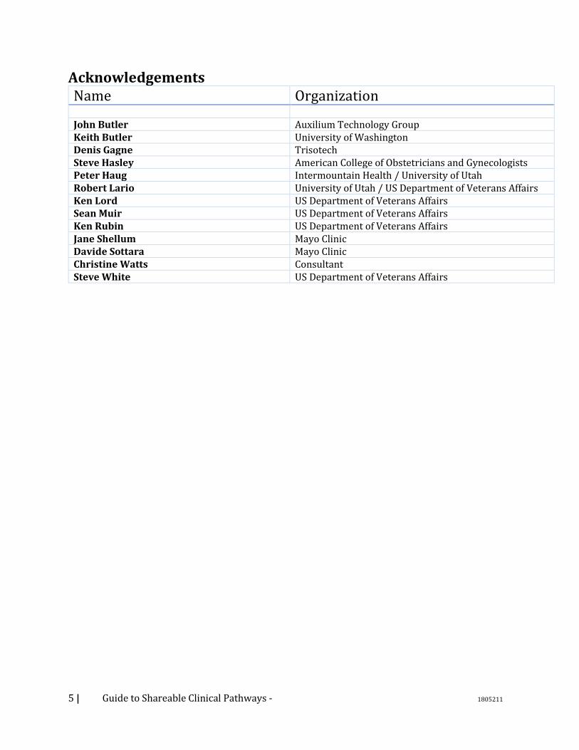
Acknowledgements Name Organization John Butler Auxilium Technology Group Keith Butler University of Washington Denis Gagne Trisotech Steve Hasley American College of Obstetricians and Gynecologists Peter Haug Intermountain Health / University of Utah Robert Lario University of Utah / US Department of Veterans Affairs Ken Lord US Department of Veterans Affairs Sean Muir US Department of Veterans Affairs Ken Rubin US Department of Veterans Affairs Jane Shellum Mayo Clinic Davide Sottara Mayo Clinic Christine Watts Consultant Steve White US Department of Veterans Affairs
6 | Guide to Shareable Clinical Pathways - 1805211
Executive Summary Need Healthcare throughout the world is growing in expense and complexity. As new technologies and medications are developed, and new care options become available, the ability for the healthcare community to provide quality care is improving and yet the risks of complications and miscommunications are greater without a better understanding of data and workflow requirements in a multi-provider healthcare environment. The great potential for health information technology (HIT) to improve the efficiency and quality of clinical health care has yet to be fully realized on a consistent, industry-wide basis. Despite major increases in the power and flexibility of computing there remains a gap between our ability to implement technology and our ability to understand how that technology will impact the performance of care. Synchrony between information flow and the appropriate workflow of clinical care is a key principle for usability, efficiency, and care quality. When HIT design decisions are not based on improving the efficiency and quality of clinical health care, the resulting solution can rearrange clinical workflow by accident rather than by design. This Guide aims to make an explicit, understandable connection between HIT and the methodical improvement of clinical health care.
Approach This Field Guide to Shareable Clinical Pathways focuses on a model-based approach to define the workflow of care and decision-making at the level of granularity that reveals information needs. The approach of this Field Guide is to apply standard techniques for business process modeling and for decision modeling that are proven for other industries and apply them to the distinct aspects of the workflow of care and decision-making. The Business Process Model and Notation (BPMN) standard is our choice for workflows. BPMN is a formal graphical and computable language that was developed to diagram processes that are performed by teams of people who must coordinate their activity while using computing to support both information work and physical activities that use and change information. A key goal is to foster community building among all types of stakeholders. The use of a well-defined standard to create workflow diagrams promotes a common understanding of their meaning by different participants. The Case Management Model and Notation (CMMN) complements BPMN with additional capabilities for unstructured behaviors triggered and continuously influenced by the information flowing into the case. Similarly, the Decision Model and Notation (DMN) standard was chosen because it provides an understandable table format to model the combinations of factors that must be considered for complex, clinical decisions. Our experience indicates the visual diagrams of BPMN and with the decision tables of DMN can be learned quickly by clinical personnel with minimal training to critique them for accuracy and appropriateness, thus allowing them to participate in decisions about HIT impact. This Field Guide provides examples in which clinical personnel played key roles in workflow and decision modeling with these standards.
Conclusion There are many reasons to develop a clear understanding of clinical care and decision making. In the most general terms, if we do not have a model-based understanding of how care is performed currently, then we cannot analyze and design cost effective improvements. Without cost-effective improvements, we cannot address the US and international critical need to improve efficiency, control the growth of health care expense, or continue to improve quality. This Field Guide is

7 | Guide to Shareable Clinical Pathways - 1805211
offered as a practical step towards realizing the great potential of HIT’s role for accessible, efficient, and high quality health care.
8 | Guide to Shareable Clinical Pathways - 1805211
Table of Contents
Contents Need ......................................................................................................................................................................................... 6
Approach ................................................................................................................................................................................ 6
Conclusion ............................................................................................................................................................................. 6
1. Scope ................................................................................................................................................................................. 14
1.1. Content ................................................................................................................................................................... 14
1.2. Motivation ............................................................................................................................................................. 14
1.3. Goal .......................................................................................................................................................................... 14
1.4. Audience ................................................................................................................................................................ 14
1.5. Defining what Success Looks Like ............................................................................................................... 15
2. Introduction ................................................................................................................................................................... 16
2.1. What is a Shareable Clinical Pathway? ...................................................................................................... 17
3. Reading Models............................................................................................................................................................. 20
3.1. Differentiating process (BPMN) vs case (CMMN) ................................................................................. 20
3.2. Business Process Modeling Notation (BPMN) for Hello Patient..................................................... 21
3.2.1. Events (Start, Intermediate & End) ..................................................................................................... 21
3.2.2. Tasks and Activities .................................................................................................................................... 22
3.2.3. Lanes and Pools ........................................................................................................................................... 23
3.2.4. Gateways ......................................................................................................................................................... 23
3.2.5. Data Object ..................................................................................................................................................... 24
3.2.6. Connectors – Sequence, Message Flows and Associations ........................................................ 24
3.3. Case Management Modeling Notation (CMMN) for Hello Patient ................................................. 26
3.3.1. Case Plan Model ........................................................................................................................................... 27
3.3.2. Tasks ................................................................................................................................................................. 27
3.3.3. Milestone ........................................................................................................................................................ 28
3.3.4. Entry and Exit Criterion ........................................................................................................................... 28
3.3.5. Case file (item).............................................................................................................................................. 29
3.4. Hello world Doctor Visit Decision Modeling Notation (DMN) ......................................................... 29
3.4.1. Decision ........................................................................................................................................................... 29
3.4.2. Business Knowledge Model .................................................................................................................... 30
3.4.3. Knowledge Source ...................................................................................................................................... 30
3.4.4. Information Requirement ........................................................................................................................ 30
3.4.5. Authority Requirement ............................................................................................................................. 30
3.4.6. Annotation ..................................................................................................................................................... 30
9 | Guide to Shareable Clinical Pathways - 1805211
3.4.7. Hit Policy ......................................................................................................................................................... 31
3.4.8. Inputs Data ..................................................................................................................................................... 31
3.4.9. Output. ............................................................................................................................................................. 31
3.4.10. Condition ................................................................................................................................................... 31
3.4.11. Row .............................................................................................................................................................. 32
4. Producing Models ........................................................................................................................................................ 33
4.1.1. Qualities of Sharable Clinical Pathways ............................................................................................. 33
4.1.2. Project High-Level Best Practices ......................................................................................................... 34
4.1.3. Methodology for Clinical Pathway Modeling ................................................................................... 35
4.2. High-Level Modeling Best Practices ........................................................................................................... 36
4.3. Sharable Clinical Pathway Models .............................................................................................................. 36
4.3.1. Architectural Scope Diagram.................................................................................................................. 36
4.3.2. Clinical Pathway Glossary/5WH Model ............................................................................................. 38
4.3.3. BPMN Process Models ............................................................................................................................... 51
4.3.4. CMMN Case Models .................................................................................................................................... 54
4.3.5. DMN Decision Models................................................................................................................................ 55
4.4. Relationships Between Clinical Pathway Models ................................................................................. 57
4.4.1. Choosing between BPMN and CMMN ................................................................................................. 57
4.4.2. Use a Case (CMMN) at the Top of the Model Hierarchy .............................................................. 59
4.4.3. Connection between BPMN and DMN ................................................................................................ 60
4.4.4. Connection between CMMN and DMN ............................................................................................... 63
5. Consuming Models ...................................................................................................................................................... 66
5.1. Introduction ......................................................................................................................................................... 66
5.2. Discovery Phase .................................................................................................................................................. 66
5.3. Assessment Phase .............................................................................................................................................. 66
5.3.1. Applicability .................................................................................................................................................. 66
5.3.2. Simulation ...................................................................................................................................................... 66
5.3.3. Acceptance ..................................................................................................................................................... 66
5.3.4. Localization Phase ...................................................................................................................................... 67
5.4. Information, Semantics and Terminologies ............................................................................................ 67
5.5. Implementation Phase ..................................................................................................................................... 67
5.5.1. Automated versus Manual Utilization ................................................................................................ 67
5.5.2. Standards-Based Technologies ............................................................................................................. 69
6. Appendix A – The Information Ecology of Clinical Care .............................................................................. 76
7. Appendix B – Design Patterns ................................................................................................................................ 78
7.1. DMN: Simple Scoring Algorithm .................................................................................................................. 78

10 | Guide to Shareable Clinical Pathways - 1805211
7.1.1. Description ..................................................................................................................................................... 78
7.1.2. Problem ........................................................................................................................................................... 78
7.1.3. Applicability .................................................................................................................................................. 79
7.1.4. Pattern ............................................................................................................................................................. 79
7.1.5. Specific Example .......................................................................................................................................... 80
7.2. DMN: Quantify – Interpret - Recommend (QIR) .................................................................................... 82
7.2.1. Description ..................................................................................................................................................... 82
7.2.2. Problem ........................................................................................................................................................... 82
7.2.3. Applicability .................................................................................................................................................. 82
7.2.4. Pattern ............................................................................................................................................................. 83
7.2.5. Specific Example .......................................................................................................................................... 86
7.3. BPMN / DMN: Decision / Action .................................................................................................................. 88
7.3.1. Description ..................................................................................................................................................... 88
7.3.2. Problem ........................................................................................................................................................... 88
7.3.3. Applicability .................................................................................................................................................. 88
7.3.4. Pattern ............................................................................................................................................................. 88
7.3.5. Specific Example .......................................................................................................................................... 89
7.4. BPMN / DMN: Workflow-Interleaved Decisions Description .......................................................... 90
7.4.1. Problem ........................................................................................................................................................... 90
7.4.2. Applicability .................................................................................................................................................. 90
7.4.3. Specific Example .......................................................................................................................................... 90
7.5. DMN: Team-based decision ........................................................................................................................... 92
7.5.1. Description ..................................................................................................................................................... 92
7.5.2. Problem ........................................................................................................................................................... 92
7.5.3. Applicability .................................................................................................................................................. 92
7.5.4. Pattern ............................................................................................................................................................. 93
7.5.1. Specific Example .......................................................................................................................................... 94
7.6. DMN: Computer-aided decision support (CDS) ..................................................................................... 95
7.6.1. Description ..................................................................................................................................................... 95
7.6.2. Problem ........................................................................................................................................................... 95
7.6.3. Applicability .................................................................................................................................................. 95
7.6.4. Pattern ............................................................................................................................................................. 96
7.6.5. Specific Example .......................................................................................................................................... 97
7.7. DMN: Multi-perspective (Treatment) Decision ..................................................................................... 98
7.7.1. Description ..................................................................................................................................................... 98
7.7.2. Problem ........................................................................................................................................................... 98
11 | Guide to Shareable Clinical Pathways - 1805211
7.7.3. Applicability .................................................................................................................................................. 98
7.7.4. Pattern ............................................................................................................................................................. 99
7.7.5. Specific Example ....................................................................................................................................... 100
7.8. DMN: Team-based decision ........................................................................................................................ 101
7.8.1. Description .................................................................................................................................................. 101
7.8.2. Problem ........................................................................................................................................................ 101
7.8.3. Applicability ............................................................................................................................................... 101
7.8.4. Specific Example ....................................................................................................................................... 101
8. Appendix C – Sustainment and Governance .................................................................................................. 104
8.1. Governance Goals ............................................................................................................................................ 104
8.2. Content Management..................................................................................................................................... 105
8.3. Asset Management. ......................................................................................................................................... 106
8.4. Choosing an Ecosystem ................................................................................................................................ 106
9. Appendix D – Glossary of Terms......................................................................................................................... 108
10. Appendix E – Hello Patient Models ............................................................................................................... 110
11. Suggested Readings ............................................................................................................................................. 113
12. Future Work ........................................................................................................................................................... 114
12 | Guide to Shareable Clinical Pathways - 1805211
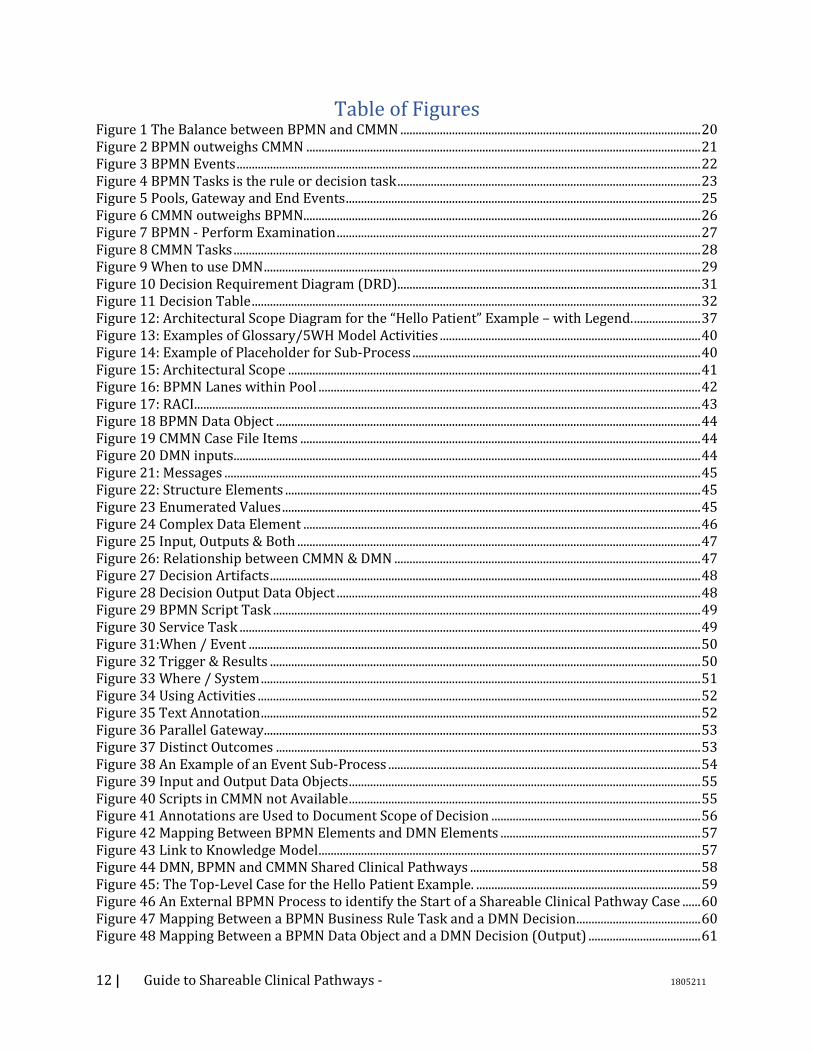
Table of Figures Figure 1 The Balance between BPMN and CMMN ................................................................................................... 20 Figure 2 BPMN outweighs CMMN .................................................................................................................................. 21 Figure 3 BPMN Events ......................................................................................................................................................... 22 Figure 4 BPMN Tasks is the rule or decision task .................................................................................................... 23 Figure 5 Pools, Gateway and End Events ..................................................................................................................... 25 Figure 6 CMMN outweighs BPMN................................................................................................................................... 26 Figure 7 BPMN - Perform Examination ........................................................................................................................ 27 Figure 8 CMMN Tasks .......................................................................................................................................................... 28 Figure 9 When to use DMN ................................................................................................................................................ 29 Figure 10 Decision Requirement Diagram (DRD).................................................................................................... 31 Figure 11 Decision Table .................................................................................................................................................... 32 Figure 12: Architectural Scope Diagram for the “Hello Patient” Example – with Legend. ...................... 37 Figure 13: Examples of Glossary/5WH Model Activities ...................................................................................... 40 Figure 14: Example of Placeholder for Sub-Process ............................................................................................... 40 Figure 15: Architectural Scope ........................................................................................................................................ 41 Figure 16: BPMN Lanes within Pool .............................................................................................................................. 42 Figure 17: RACI ....................................................................................................................................................................... 43 Figure 18 BPMN Data Object ............................................................................................................................................ 44 Figure 19 CMMN Case File Items .................................................................................................................................... 44 Figure 20 DMN inputs .......................................................................................................................................................... 44 Figure 21: Messages ............................................................................................................................................................. 45 Figure 22: Structure Elements ......................................................................................................................................... 45 Figure 23 Enumerated Values .......................................................................................................................................... 45 Figure 24 Complex Data Element ................................................................................................................................... 46 Figure 25 Input, Outputs & Both ..................................................................................................................................... 47 Figure 26: Relationship between CMMN & DMN ..................................................................................................... 47 Figure 27 Decision Artifacts .............................................................................................................................................. 48 Figure 28 Decision Output Data Object ........................................................................................................................ 48 Figure 29 BPMN Script Task ............................................................................................................................................. 49 Figure 30 Service Task ........................................................................................................................................................ 49 Figure 31:When / Event ..................................................................................................................................................... 50 Figure 32 Trigger & Results .............................................................................................................................................. 50 Figure 33 Where / System ................................................................................................................................................. 51 Figure 34 Using Activities .................................................................................................................................................. 52 Figure 35 Text Annotation ................................................................................................................................................. 52 Figure 36 Parallel Gateway ................................................................................................................................................ 53 Figure 37 Distinct Outcomes ............................................................................................................................................ 53 Figure 38 An Example of an Event Sub-Process ....................................................................................................... 54 Figure 39 Input and Output Data Objects .................................................................................................................... 55 Figure 40 Scripts in CMMN not Available .................................................................................................................... 55 Figure 41 Annotations are Used to Document Scope of Decision ..................................................................... 56 Figure 42 Mapping Between BPMN Elements and DMN Elements .................................................................. 57 Figure 43 Link to Knowledge Model .............................................................................................................................. 57 Figure 44 DMN, BPMN and CMMN Shared Clinical Pathways ............................................................................ 58 Figure 45: The Top-Level Case for the Hello Patient Example. .......................................................................... 59 Figure 46 An External BPMN Process to identify the Start of a Shareable Clinical Pathway Case ...... 60 Figure 47 Mapping Between a BPMN Business Rule Task and a DMN Decision ......................................... 60 Figure 48 Mapping Between a BPMN Data Object and a DMN Decision (Output) ..................................... 61
13 | Guide to Shareable Clinical Pathways - 1805211
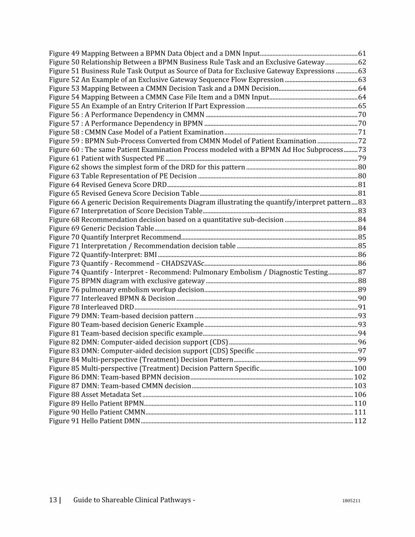
Figure 49 Mapping Between a BPMN Data Object and a DMN Input ............................................................... 61 Figure 50 Relationship Between a BPMN Business Rule Task and an Exclusive Gateway ..................... 62 Figure 51 Business Rule Task Output as Source of Data for Exclusive Gateway Expressions .............. 63 Figure 52 An Example of an Exclusive Gateway Sequence Flow Expression ............................................... 63 Figure 53 Mapping Between a CMMN Decision Task and a DMN Decision ................................................... 64 Figure 54 Mapping Between a CMMN Case File Item and a DMN Input ......................................................... 64 Figure 55 An Example of an Entry Criterion If Part Expression ........................................................................ 65 Figure 56 : A Performance Dependency in CMMN .................................................................................................. 70 Figure 57 : A Performance Dependency in BPMN ................................................................................................... 70 Figure 58 : CMMN Case Model of a Patient Examination ...................................................................................... 71 Figure 59 : BPMN Sub-Process Converted from CMMN Model of Patient Examination .......................... 72 Figure 60 : The same Patient Examination Process modeled with a BPMN Ad Hoc Subprocess ......... 73 Figure 61 Patient with Suspected PE ............................................................................................................................ 79 Figure 62 shows the simplest form of the DRD for this pattern ........................................................................ 80 Figure 63 Table Representation of PE Decision ....................................................................................................... 80 Figure 64 Revised Geneva Score DRD ........................................................................................................................... 81 Figure 65 Revised Geneva Score Decision Table ...................................................................................................... 81 Figure 66 A generic Decision Requirements Diagram illustrating the quantify/interpret pattern .... 83 Figure 67 Interpretation of Score Decision Table .................................................................................................... 83 Figure 68 Recommendation decision based on a quantitative sub-decision ............................................... 84 Figure 69 Generic Decision Table ................................................................................................................................... 84 Figure 70 Quantify Interpret Recommend .................................................................................................................. 85 Figure 71 Interpretation / Recommendation decision table .............................................................................. 85 Figure 72 Quantify-Interpret: BMI ................................................................................................................................. 86 Figure 73 Quantify - Recommend – CHADS2VASc ................................................................................................... 86 Figure 74 Quantify - Interpret - Recommend: Pulmonary Embolism / Diagnostic Testing ................... 87 Figure 75 BPMN diagram with exclusive gateway .................................................................................................. 88 Figure 76 pulmonary embolism workup decision ................................................................................................... 89 Figure 77 Interleaved BPMN & Decision ..................................................................................................................... 90 Figure 78 Interleaved DRD ................................................................................................................................................ 91 Figure 79 DMN: Team-based decision pattern ......................................................................................................... 93 Figure 80 Team-based decision Generic Example ................................................................................................... 93 Figure 81 Team-based decision specific example .................................................................................................... 94 Figure 82 DMN: Computer-aided decision support (CDS) ................................................................................... 96 Figure 83 DMN: Computer-aided decision support (CDS) Specific .................................................................. 97 Figure 84 Multi-perspective (Treatment) Decision Pattern ................................................................................ 99 Figure 85 Multi-perspective (Treatment) Decision Pattern Specific ............................................................ 100 Figure 86 DMN: Team-based BPMN decision ......................................................................................................... 102 Figure 87 DMN: Team-based CMMN decision ........................................................................................................ 103 Figure 88 Asset Metadata Set ........................................................................................................................................ 106 Figure 89 Hello Patient BPMN....................................................................................................................................... 110 Figure 90 Hello Patient CMMN ...................................................................................................................................... 111 Figure 91 Hello Patient DMN ......................................................................................................................................... 112

14 | Guide to Shareable Clinical Pathways - 1805211
1. Scope
1.1. Content
This field guide focuses on Sharable Clinical Pathways. Clinical Pathways are sometimes referred to
as Clinical Guidelines, Clinical Workflows, Integrated Care Pathways, Multidisciplinary Pathways of
Care and some other variances. When used herein, Clinical Pathways means “structured,
multidisciplinary plans of care designed to support the implementation of clinical guidelines and
protocols. Clinical pathways have four main components: a timeline, the categories of care or
activities and their interventions, intermediate and long-term outcome criteria, and the variance
record (to allow deviations to be documented and analyzed)1.
To make Clinical Pathways shareable it is recommended to use internationally accepted standards
where possible. In particular, this Field Guide provides guidance on using Business Process Model
and Notation (BPMN), Case Management Model and Notation (CMMN), and Decision Model and
Notation (DMN). These models have definable entry points, exit points, goals, and roles, are
organized around a specific clinical topic, and are intended to be sharable across organizations. The
models allow for localization while maintaining the essence of the clinical pathway. Examples used
in the field guide were developed by a work group who used BPMN, CMMN, and DMN to create an
example clinical pathway for antenatal care. These examples highlight the use of these notations
with applicable constraints, extensions, and intersections with other formalisms.
1.2. Motivation
The use of these three modeling notations, particularly BPMN, is well established in business.
However, the healthcare environment presents unique challenges which prompted the creation of
this Field Guide. Perhaps more so than in other domains, health information technology systems are
defined in terms of human tasks, both manual and cognitive, as well as computational tasks. The
information resides in multiple locations, including not only the computer systems, but in paper
documents, white boards, equipment, the observable environment, and the patient. Information
exchange and transformation are complex, and a piece of information may be the object of work in
one subprocess, and a resource in another. Workflows and information flows run in parallel and
intersect at multiple points in multiple ways.
1.3. Goal
The Field Guide to Shareable Clinical Pathways is applicable to processes occurring in the course of
providing care, including clinical, administrative, and revenue cycle processes, with an emphasis on
the clinical processes. The goal of the Field Guide is to enable modeling of multi-team processes
within organizations and sharing processes between organizations.
1.4. Audience
This Field Guide is targeted at healthcare professional staff with responsibility for capturing,
documenting, vetting, and deploying processes and workflows within an organization. The
expectation is that these staff either will have (or will be trained for) a working understanding of
the modeling formalisms that are used within this document.
1 http://www.openclinical.org/clinicalpathways.html
15 | Guide to Shareable Clinical Pathways - 1805211
The remainder of the document is divided into three sections that focus on the role they have
within the organization in relation to clinical pathways. The three Field Guide audience roles are
these:
• Readers should be familiar enough with the three modeling standards (BPMN, CMMN, and DMN) so that they can view and understand the basic behaviors defined in those models (see “Reading Models,” below). Readers are not expected to understand all the technical model definitions necessary for model execution; nor are they expected develop Shareable Clinical Pathways.
Note that it is not expected that front-line healthcare providers will be reading the Shareable Clinical Pathway models. However, those healthcare professionals that are responsible for ensuring that clinical pathways are properly performed within their organization should be able to read and understand Shareable Clinical Pathways.
• Producers should be well-versed in the three modeling standards (BPMN, CMMN, and DMN) to the extent that they can follow this Field Guide to create consistent and valid Shareable Clinical Pathways (see “Producing Models,” below).
• Consumers should be well-versed in the three modeling standards (BPMN, CMMN, and DMN) and the technologies available to the organization that will enable implementation of the Shareable Clinical Pathways. Consumers will “localize” the Shareable Clinical Pathways to fit within their organization’s technical capabilities (see “Consuming Models,” below).
1.5. Defining what Success Looks Like
Simply put, this document is intended to be handed to a member of a “modeling team”, and when
that individual follows the guidance here, the resultant work product would be “sharable” (e.g.
portable) with other institutions. In other words, the systematic application of the method and
style described within this Field Guide should ensure portability of the work products within or
between institutions, namely “Sharable Clinical Pathways”.
As a result, the specific content of this guide will provide actionable, testable, implementable
criteria to influence how models are conceived, created, documented, and expressed. Stylistic
guidance will provide clear direction to allow for consistency and repeatability across process flows
and institutions of care. Compliance criteria will be objective and evidence-based, allowing for
objective evaluation.
16 | Guide to Shareable Clinical Pathways - 1805211
2. Introduction Providing consistently high-quality healthcare is difficult. The demands on healthcare providers
and complexity of the healthcare system seem to be increasing exponentially. Medical knowledge is
expanding so rapidly that it is almost impossible to keep up without the support of health
information technology. Providing health care is a complex process, involving multidisciplinary
teams with multiple handoffs across care settings. Increasingly, systems supporting coordinated
care teams are demonstrating the ability to achieve better outcomes. But because of the complexity
of healthcare, such systems are costly to design, build, and maintain, and extremely challenging to
share between organizations. But if the designs for these complex systems could be developed in
way that they could be shared between organizations, and tailored to fit within a particular
environment, then the entire healthcare community could benefit.
Fortunately, the healthcare community has a unique asset it can leverage to address these
challenges: the proven ability of the community to collaborate and share data, information, and
knowledge. Collaboration is built into the DNA of medicine and medical research. Likewise, the
healthcare technology community, including standards organizations such as SNOMED and Health
Level-7, and professional organizations such as the American Medical Informatics Association,
Health Information and Management Systems Society, and American Health Information
Management Association have a culture of collaboration and innovation as well as a commitment to
reducing the technical barriers to delivering high quality health care. In particular, numerous health
information technology groups have attempted to create “computer interpretable guidelines”
aimed at leveraging technology to support clinical workflows. These groups developed various
healthcare specific modeling languages and approaches, but none has been widely adopted and
applied.
The Business Process Management in Health Workgroup (BPMHW) of the Object Management
Group (OMG) was formed to demonstrate the suitability of existing OMG modeling standards for
publishing, sharing, and applying models and specification documents that describe clinical
pathways, with a goal of accelerating the development of health information technology solutions.
The workgroup brings together participants with experience in healthcare standards and technical
standards. The OMG is well suited for this work; like healthcare technology organizations, the OMG
as a community has collaboration in its DNA. The OMG has over 20 years of experience in defining
standards for developing and documenting complex systems with shareable, re-usable, and
extensible models and design documents.
The OMG’s current standard languages, such Business Process Model and Notation (BPMN), Case
Management Model and Notation (CMMN), and Decision Model and Notation (DMN) provide a solid foundation of formal semantics to model complex systems across business domains. There already
exists a large international community of commercial and open source tools that support these
standards.
The Field Guide to Shareable Clinical Pathways has been created by the BPMHW as a handbook to
help business analysts and knowledge engineers create models, clinical experts understand and
validate models, and programmers and systems analysts implement the models. The Field Guide
will leverage the work and lessons learned of the BPMHW Pilot Group who are modeling actual,
implementable clinical pathways based on identified healthcare use cases. As time permits and the
community grows, this approach will lead to a growing library of sharable clinical process
documents.
17 | Guide to Shareable Clinical Pathways - 1805211
The core principles of the BPMHW are:
• Address workflow modeling of healthcare systems with a focus on clinical pathways. • Leverage and use current standards, both healthcare specific and general technical standard
whenever possible. • Incorporate existing systems into the new innovative solutions. A “greenfield” approach is not
appropriate given the urgency of these solutions and the existing human and capital investment in existing systems.
• Process design documents must be actionable. • Process design documents must be sharable, re-usable, customizable, and extensible.
2.1. What is a Shareable Clinical Pathway?
A clinical pathway defines the activities, data, and goals of a specific topic of care for a patient (e.g.,
Oncology, Antenatal Care). In general, a clinical pathway is the information and actions that provide
for the enactment of a patient’s Care Plan2. Well documented clinical pathways can improve
communication by providing consistent and coordinated workflow steps and goals to, patients, and
care team members to ensure common practices and results. Further, the clinical pathways will
help define the data requirements necessary for interoperability between systems and healthcare
organizations. It is with this coordination that clinical pathways aim to improve the coordination
and outcomes of care over time.
Clinical pathways can be in the form of narrative text, which is understandable for health care
professionals and business analysts but is open to large variations of interpretation. To make them
useful as the basis for implementing health care workflows or decision support systems they must be made explicit with formal, repeatable semantics. Some recent efforts, such as Health Level Seven
(HL7) Knowledge Artifacts and FHIR Plan Definitions use formal programming languages to define
the workflow of Clinical Pathways. These programming languages provide the tools necessary for
developers to implement health care workflows or decision support systems. However, they are not
readily understandable by health care professionals and business analysts. Furthermore, both text
narratives and programming languages are difficult to maintain over time, since there is no clear
way to pinpoint where changes should be made to the definitions due to changes in the
environment or technology.
To improve the capabilities and usability of clinical pathway definitions, the BPMHW has developed
a new approach. Using the Guide to Shareable Clinical Pathways, which describes a lightweight
methodology for utilizing three OMG standards, business analysts, rather than IT staff, can develop
Shareable Clinical Pathways. The three standards are the Business Process Model and Notation
(BPMN), the Case Management Model and Notation (CMMN), and the Decision Model and Notation
(DMN) specifications. A Shareable Clinical Pathways should be designed in a way that if Care Plans
derived from the application of a pathway to a given patient are successfully executed, then that
patient’s care (delivery) experience will comply with clinical guidelines.
Through the graphical notations provided by the standards, which are backed by execution
semantics, Shareable Clinical Pathways provide technological rigor yet are understandable by
business analysts and healthcare professionals. A single Shareable Clinical Pathway may be
comprised of combination of BPMN, CMMN, and DMN models. These are linked together to provide
2 https://www.hl7.org/fhir/careplan.html
18 | Guide to Shareable Clinical Pathways - 1805211
a detailed knowledge artifact describing the work, data, and decision requirements of a clinical
pathway.
Shareable Clinical Pathways are of value to healthcare organizations in the following ways:
• They follow a model-driven approach: Shareable Clinical Pathways are Platform Independent Models (PIMs).
They identify the work and data requirements of a clinical pathway, but do not define a specific platform for its implementation.
Consumers of a Shareable Clinical Pathway will create a Platform Specific Model (PSM) that localizes the workflow to the technology available to that consumer.
• Thus, they are shareable:
Shareable Clinical Pathways can be produced by one organization and that pathway can be utilized and localized by another organization or across multiple sites within the same organization.
The localizations of a Shareable Clinical Pathway will satisfy the defined work and data requirements. That is, the execution of the Shareable Clinical Pathway will provide consistent results in spite of different implementation details.
• The models of a Shareable Clinical Pathway can be understood by business analysts, healthcare professionals, and IT developers.
The behavioral requirements of a Shareable Clinical Pathway can be directly validated by the healthcare professionals responsible for their implementation; instead of “throwing them over the wall” to IT developers, trusting that the programming language code will meet those requirements.
• Shareable Clinical Pathways are based on domain-independent BPM standards.
The BPM standards are semantically rich enough to provide the behavioral capabilities required to define workflows for the healthcare domain.
BPM standards are supported by a wide range of modeling and execution tools (e.g., there are 80+ tools that support BPMN).
There are multiple sources of documentation and training for the standards, including university courses.
Thus, there is an increasing pool of trained modelers for the standards that can be used instead of training staff to learn a new, healthcare-specific programming language.
• The BPM Healthcare Field Guide provides the basis for Shareable Clinical Pathways to be developed in a consistent manner across multiple organizations.

19 | Guide to Shareable Clinical Pathways - 1805211

20 | Guide to Shareable Clinical Pathways - 1805211
3. Reading Models The purpose of this section is to provide the Reader with a quick overview of the major elements within the three modeling perspective (BPMN, CMMN, & DMN): process modeling, case modeling, and decision modeling. The section will also provide the reader with depictions of a simple Sharable Clinical Pathway example called “Hello Patient” and explanations of the highlighted element(s). References for further reading of the modeling languages will be provided. The “Hello Patient” example used within this section is based on a doctor visit. Although the models shown are meant to be accurate and representative of a doctor visit, they are for illustration purposes only; as such they are not necessarily complete or generalizable. This section is not meant to be a tutorial, but rather a contextual overview of key elements.
3.1. Differentiating process (BPMN) vs case (CMMN) Sharable Clinical Pathways can be captured using a combination of both process (BPMN) and case (CMMN). It is therefore useful to understand the difference between them. A Producer of a Shareable Clinical Pathway must determine which of the two model languages is appropriate for a particular set of activities. Many Shared Clinical Pathways will use both type of models to accurately define the workflow of the pathway. When a portion of a clinical pathway’s preferred sequence is known and fairly deterministic (i.e., structured work), it can be documented and modeled using BPMN. However, when a portion of the pathway is more “event-driven” (i.e., unstructured work), such as with doctor examinations, CMMN may provide a more appropriate set of modeling elements and associated notation. The figure below illustrates the balance between the two modeling languages.
Figure 1 The Balance between BPMN and CMMN
In actuality, there is no hard line to force the decision between the two languages. There are many sets of activities that can be modeled with either one. It will be up to the Producer to choose the best fit. The table below lists other general characteristics of BPMN and CMMN languages that will help the Producer make a choice.
BPMN Characteristics CMMN Characteristics
Imperative Declarative
Activity centric Data centric
Deterministic Sequence Non-Deterministic Sequence
Guided Work Enabled Work
21 | Guide to Shareable Clinical Pathways - 1805211
Table 1 : The General Characteristics of BPMN and CMMN models
Note that DMN decision models can be useful in conjunction with both BPMN or CMMN models as a way to specify complex decision logic. The sections below will illustrate the characteristics of each type of model.
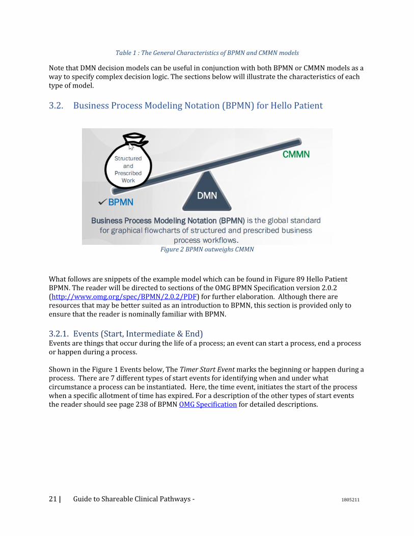
3.2. Business Process Modeling Notation (BPMN) for Hello Patient
Figure 2 BPMN outweighs CMMN
What follows are snippets of the example model which can be found in Figure 89 Hello Patient BPMN. The reader will be directed to sections of the OMG BPMN Specification version 2.0.2 (http://www.omg.org/spec/BPMN/2.0.2/PDF) for further elaboration. Although there are resources that may be better suited as an introduction to BPMN, this section is provided only to ensure that the reader is nominally familiar with BPMN.
3.2.1. Events (Start, Intermediate & End) Events are things that occur during the life of a process; an event can start a process, end a process or happen during a process. Shown in the Figure 1 Events below, The Timer Start Event marks the beginning or happen during a process. There are 7 different types of start events for identifying when and under what circumstance a process can be instantiated. Here, the time event, initiates the start of the process when a specific allotment of time has expired. For a description of the other types of start events the reader should see page 238 of BPMN OMG Specification for detailed descriptions.

22 | Guide to Shareable Clinical Pathways - 1805211
Figure 3 BPMN Events
The Timer Intermediate Event occurs within a process as seen above in Figure 3 BPMN Events. There are two concepts to note here. The first is the notation of an intermediate event; an event occurring mid-process during an actively executing process. Intermediate events occur while a process is currently inflight; this is different from causing a process to begin execution as seen with Start Events, or ending a process as seen with End Events. Intermediate events have two thin outer circles whereas start events have one thin outer circle and end events have one thick outer circle. Second, the type of intermediate event, depicted here is a “Timer” event. Here the intermediate Timer event will cause the process to pause for a specified period of time. Other Intermediate events await a specific action or condition to occur before execution commences. The reader should see page 249 of the OMG specification for further explication of Intermediate Events. End events mark the completion of a sequence of activities. The end may be just for a branch of larger flow or terminate the entire workflow. End events are identified by a dark outlined circle; a terminating end event contains a dark dot in the center (an example is shown in Figure 5 Pools, Gateway and End Events, below). Note page 259 of the OMG specification for a table of different types of events and their corresponding explanation.
3.2.2. Tasks and Activities Tasks and Activities depict the notion of work performed in a process (note page 385 of the OMG spec). Activities in BPMN can be one of the 9 task types defined in the spec, a sub-process, or a called activity (used to link to anther process). The sub-process is shown with a small box containing cross hairs; representing the collapse of a more detailed activity definition. If tool supported, clicking on the cross hairs will open the detailed activities represented by the collapsed sub-process icon. Shown in the Figure 4 BPMN Tasks is the rule or decision task is the task “Decide Treatment Plan”. This is an activity where information is assessed and a disposition is determined. Note, this Task is distinguishable from a Gateway (See Figure 4 BPMN Tasks is the rule or decision task) in that a Gateway is a diamond-shaped element that controls the flow of the process based upon the Gateway type (more on this below).

23 | Guide to Shareable Clinical Pathways - 1805211
Figure 4 BPMN Tasks is the rule or decision task
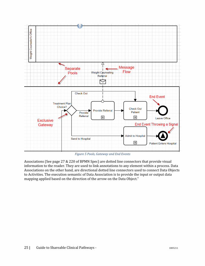
3.2.3. Lanes and Pools Lanes and Pools provide a mechanism for organizing activities. Lanes provide a visual container to organize activities within a Pool and are often associated with a business role, such as technician or primary care provider (see page 304 of the BPMN specification). They can be shown horizontally or vertically and are sometimes referred to as swim-lanes. Multiple Lanes can be used to show a sub-partitioning within a Pool (described below). Lanes are only informational for the reader and play no role in the execution of the process. Pools (see page 111 of the BPMN spec) also provide a means of organizing activities but contain an entire process. They show a complete body of work with a start and end; they are realized within a single process. When shown together within the same diagram, Pools represent the participants within a larger business collaboration. A Pool can represent an organization executing one flow, while another Pool may represent another organization’s clinical workflow, with messages communicating between the pools sharing data and maintaining synchronicity. A Pool might also represent a doctor’s office, sending messages to another Pool representing the lab performing tests. As stated above, a Pool may contain multiple lanes to help visually organize the activities depicting the roles or groups responsible for segments of the flow. It should be noted that sequence flows cannot cross Pool boundaries. Instead, Message Flows (See Figure 5 Pools, Gateway and End Events, below) are used to capture interactions between pools.
3.2.4. Gateways Gateways (see page 31 of BPMN Spec) are the point within a process where a flow may either diverge or converge. They represent control logic within the sequence of activities, but not decision logic. This is an important fact. The task of making a clinical assessment occurs within an activity, with the flow of the clinical pathway is affected by this decision. For example, determining if a patient has diabetes or a high glucose level occurs within an activity in the flow proceeding a gateway. For example, the gateway controls the next activity in the flow to execute based upon the glucose level. The condition of a flow is attached to the sequence flow exiting the gateway. How the egress (diverge) sequence flows out of a gateway is assessed by the gateway itself. Shown below in Figure 5 Pools, Gateway and End Events is a diverging exclusive gateway and a parallel gateway above. The diverging exclusive gateway (see page 286 of BPMN Spec) shows a
24 | Guide to Shareable Clinical Pathways - 1805211
situation where only one output sequence flow will be traversed; exclusive may be shown as an empty diamond or a diamond containing an “x”. With gateways all the possible pathways provided must be exhaustive, otherwise the clinical flow may deadlock. Here the clinical flow will either “Check Out” the patient, “Give Referral” to the patient, or “Send (the patient) to Hospital” determining the sequence flow. The decision on what the patient should do was determined in the “Decide Treatment Plan” activity. The Parallel gateway above shows “splitting” the flow into two parallel flows, each flow independent of the other. There are 6 different types of gateways as shown in the BPMN spec page 287.
3.2.5. Data Object Data Objects (see Figure 4 BPMN Tasks is the rule or decision task and page 27 & 221 of the BPMN Spec) identify data that is sent or received by Tasks or Activities. A Data Object may be passed through a Message between Pools. They may be assessed to affect the flow of a pathway. In addition, Data Objects can be created and updated as part of an Activity.
3.2.6. Connectors – Sequence, Message Flows and Associations Sequence and Message Flows (see page 32 of BPMN Spec) are the two types of connectors within BPMN processes that are part of the execution semantics; they affect the flow and sequence execution of the process (see Figure 5 Pools, Gateway and End Events). Sequence Flows are solid lines that act as the glue between nodes (Activities, Events and Gateways) within the clinical flow; they visually depict the order in which a flow may progress (i.e. the Sequence). As noted earlier they may only be used within a Pool. Message Flows are dashed lines that show the flow of information between processes contained within separate Pools. They show the movement of information and synchronizing events between Participants. They depict the sending or receiving of data or signals between Events or Activities in separate Pools.
25 | Guide to Shareable Clinical Pathways - 1805211
Figure 5 Pools, Gateway and End Events
Associations (See page 27 & 220 of BPMN Spec) are dotted line connectors that provide visual information to the reader. They are used to link annotations to any element within a process. Data Associations on the other hand, are directional dotted line connectors used to connect Data Objects to Activities. The execution semantic of Data Association is to provide the input or output data mapping applied based on the direction of the arrow on the Data Object.”

26 | Guide to Shareable Clinical Pathways - 1805211
3.3. Case Management Modeling Notation (CMMN) for Hello Patient
Figure 6 CMMN outweighs BPMN
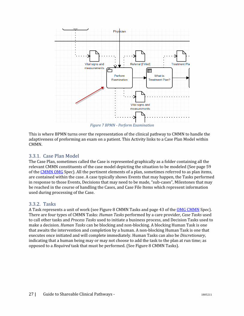
While certain clinical pathways and activities can be prescribed (deterministic) at design time – during the process of designing the model, such as making a doctor’s appointment for the flu, other processes are more ad hoc and non-deterministic. These ad hoc processes may be due to sudden and unexpected events that occur in the real world or due to known events that are unpredictable in their timing. Often the environment requires care providers to adapt to emerging and changing environmental conditions which are unexpected; during a regular prenatal care exam no heart beat is observed. As such the traditional method of representing clinical pathways using BPMN is difficult at best. An agile ad hoc environment cannot be easily represented with BPMN and requires an adaptive “case management” style of representation. This is the role of CMMN - specifying clinical responses to ad hoc events based on the “state” of the particular “case”. CMMN allows real time response to the unfolding of sudden and unforeseen events in the form of flexible choices/selection of activities as the care provider determines necessary. The reader will be directed to the OMG Case Management Modeling Notation (CMMN) Version 1.1 (http://www.omg.org/spec/CMMN/1.1/PDF) for more details. The following discussion uses the Hello Patient CMMN example shown in Figure 90 Hello Patient CMMN. As in the BPMN example, this example is for illustration purposes and is not necessarily sufficient nor complete enough to represent a patient encounter. Take a moment to look back at the BPMN model in Figure 89 Hello Patient BPMN. Note the Case Activity called “Preform Examination” in Figure 7 BPMN - Perform Examination. .
27 | Guide to Shareable Clinical Pathways - 1805211
Figure 7 BPMN - Perform Examination
This is where BPMN turns over the representation of the clinical pathway to CMMN to handle the adaptiveness of preforming an exam on a patient. This Activity links to a Case Plan Model within CMMN.
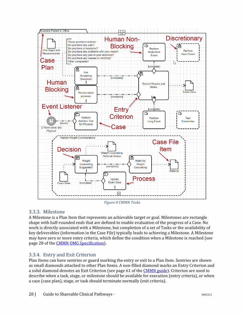
3.3.1. Case Plan Model The Case Plan, sometimes called the Case is represented graphically as a folder containing all the relevant CMMN constituents of the case model depicting the situation to be modeled (See page 59 of the CMMN OMG Spec). All the pertinent elements of a plan, sometimes referred to as plan items, are contained within the case. A case typically shows Events that may happen, the Tasks performed in response to those Events, Decisions that may need to be made, “sub-cases”, Milestones that may be reached in the course of handling the Cases, and Case File Items which represent information used during processing of the Case.
3.3.2. Tasks A Task represents a unit of work (see Figure 8 CMMN Tasks and page 43 of the OMG CMMN Spec). There are four types of CMMN Tasks: Human Tasks performed by a care provider, Case Tasks used to call other tasks and Process Tasks used to initiate a business process, and Decision Tasks used to make a decision. Human Tasks can be blocking and non-blocking. A blocking Human Task is one that awaits the intervention and completion by a human. A non-blocking Human Task is one that executes once initiated and will complete immediately. Human Tasks can also be Discretionary, indicating that a human being may or may not choose to add the task to the plan at run time; as opposed to a Required task that must be performed. (See Figure 8 CMMN Tasks).
28 | Guide to Shareable Clinical Pathways - 1805211
Figure 8 CMMN Tasks
3.3.3. Milestone A Milestone is a Plan Item that represents an achievable target or goal. Milestones are rectangle shape with half-rounded ends that are defined to enable evaluation of the progress of a Case. No work is directly associated with a Milestone, but completion of a set of Tasks or the availability of key deliverables (information in the Case File) typically leads to achieving a Milestone. A Milestone may have zero or more entry criteria, which define the condition when a Milestone is reached (see page 28 of the CMMN OMG Specification).
3.3.4. Entry and Exit Criterion Plan Items can have sentries or guard marking the entry or exit to a Plan Item. Sentries are shown as small diamonds attached to other Plan Items. A non-filled diamond marks an Entry Criterion and a solid diamond denotes an Exit Criterion (see page 61 of the CMMN guide). Criterion are used to describe when a task, stage, or milestone should be available for execution (entry criteria), or when a case (case plan), stage, or task should terminate normally (exit criteria).
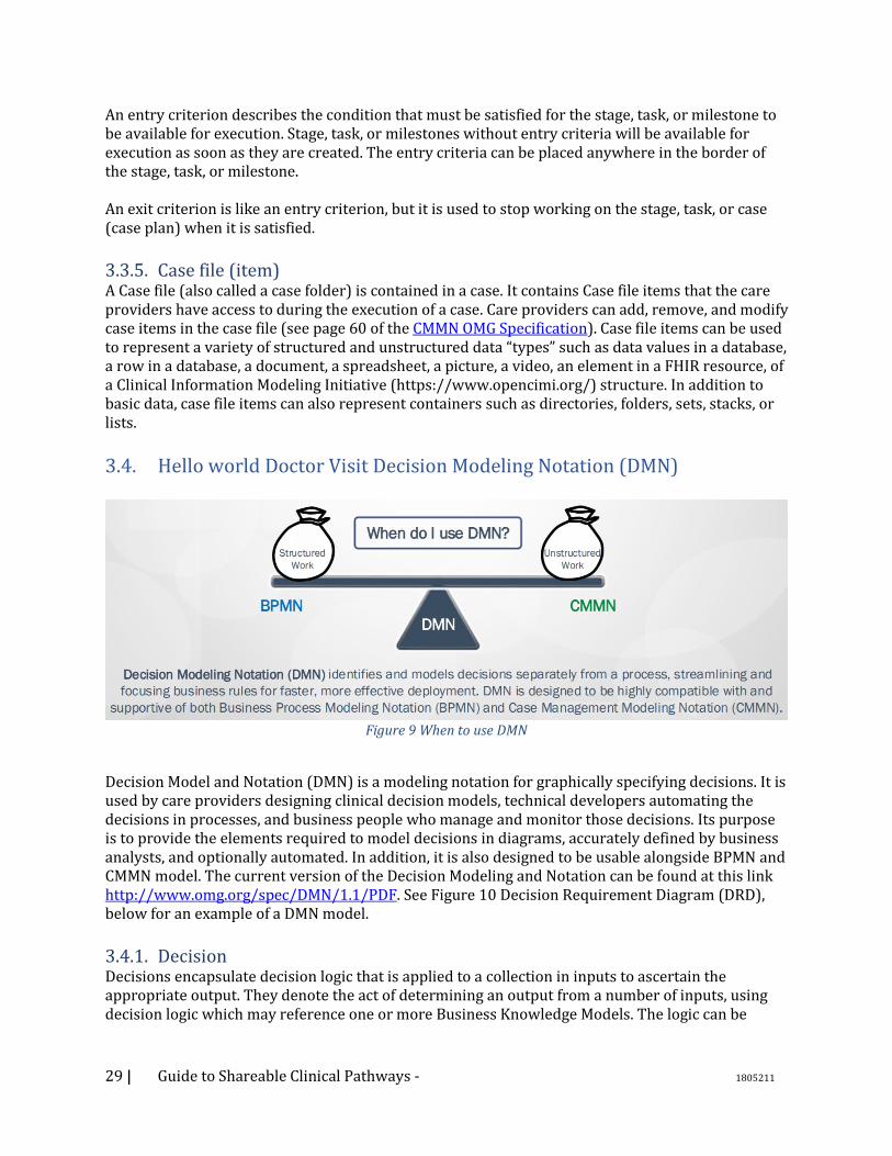
29 | Guide to Shareable Clinical Pathways - 1805211
An entry criterion describes the condition that must be satisfied for the stage, task, or milestone to be available for execution. Stage, task, or milestones without entry criteria will be available for execution as soon as they are created. The entry criteria can be placed anywhere in the border of the stage, task, or milestone. An exit criterion is like an entry criterion, but it is used to stop working on the stage, task, or case (case plan) when it is satisfied.
3.3.5. Case file (item) A Case file (also called a case folder) is contained in a case. It contains Case file items that the care providers have access to during the execution of a case. Care providers can add, remove, and modify case items in the case file (see page 60 of the CMMN OMG Specification). Case file items can be used to represent a variety of structured and unstructured data “types” such as data values in a database, a row in a database, a document, a spreadsheet, a picture, a video, an element in a FHIR resource, of a Clinical Information Modeling Initiative (https://www.opencimi.org/) structure. In addition to basic data, case file items can also represent containers such as directories, folders, sets, stacks, or lists.
3.4. Hello world Doctor Visit Decision Modeling Notation (DMN)
Figure 9 When to use DMN
Decision Model and Notation (DMN) is a modeling notation for graphically specifying decisions. It is used by care providers designing clinical decision models, technical developers automating the decisions in processes, and business people who manage and monitor those decisions. Its purpose is to provide the elements required to model decisions in diagrams, accurately defined by business analysts, and optionally automated. In addition, it is also designed to be usable alongside BPMN and CMMN model. The current version of the Decision Modeling and Notation can be found at this link http://www.omg.org/spec/DMN/1.1/PDF. See Figure 10 Decision Requirement Diagram (DRD), below for an example of a DMN model.
3.4.1. Decision Decisions encapsulate decision logic that is applied to a collection in inputs to ascertain the appropriate output. They denote the act of determining an output from a number of inputs, using decision logic which may reference one or more Business Knowledge Models. The logic can be
30 | Guide to Shareable Clinical Pathways - 1805211
expressed as a decision table, a literal expression (Feel), relationship table, and/or boxed expression. See page 20 of the DMN specification for further information.
3.4.2. Business Knowledge Model A Business Knowledge Model (BKM) (see Figure 10 Decision Requirement Diagram (DRD)) is a function encapsulating business knowledge. The logic of the encapsulated business knowledge can be expressed using a relationship table, a FEEL literal expression, a decision table, a Java Class, and/or an analytical model captured in PMML analytic model. BKMs are essentially reusable decisions.
3.4.3. Knowledge Source Knowledge Sources (see Figure 10 Decision Requirement Diagram (DRD)) help document the authority or source of the logic within a decision. Knowledge Sources are informational only and have no effect on the execution of the model by a computer if the models were executed. They are used to help add clarity for the reader of the models. They depict the authority for a Business Knowledge Model or Decision. The knowledge source that impacts a Decision is linked via an Authority Requirement.
3.4.4. Information Requirement An Information Requirement (see Figure 10 Decision Requirement Diagram (DRD)) depicts data or a decision output being used as one of the inputs of a decision. Decisions are linked to other decisions shown using a solid line with a solid arrow head. The line represents an output from one Decision becoming an Information Requirement to another Decision (Figure 10 Decision Requirement Diagram (DRD)).
3.4.5. Authority Requirement An Authority Requirement (see Figure 10 Decision Requirement Diagram (DRD)) denotes the dependence of a DMN Requirement Diagram (DRD) (See Figure 10 Decision Requirement Diagram (DRD)) element on another DRD element that acts as a source of guidance or knowledge.
3.4.6. Annotation An Annotation (see Figure 10 Decision Requirement Diagram (DRD)) is an explanatory text or comment that is added to a diagram to provide clarity for the reader and has no impact on the execution of the decision logic.
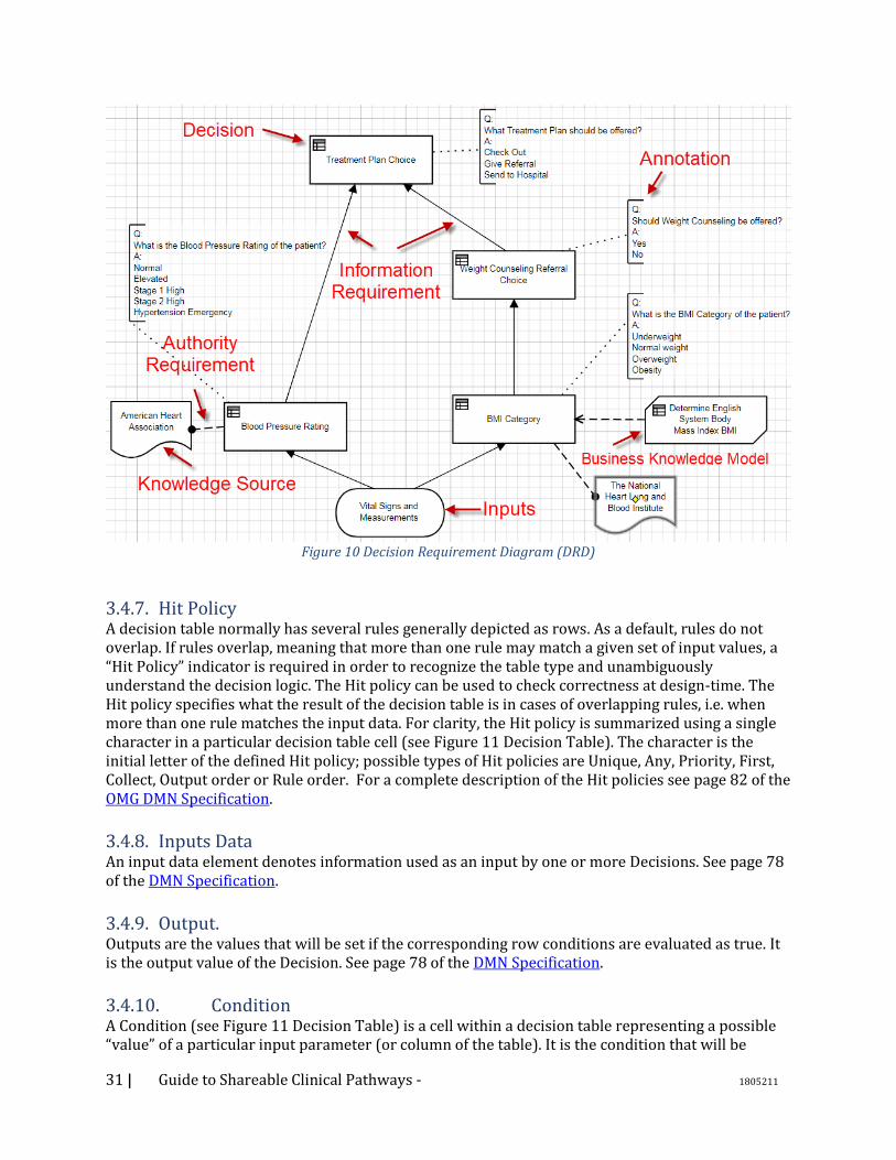
31 | Guide to Shareable Clinical Pathways - 1805211
Figure 10 Decision Requirement Diagram (DRD)
3.4.7. Hit Policy A decision table normally has several rules generally depicted as rows. As a default, rules do not overlap. If rules overlap, meaning that more than one rule may match a given set of input values, a “Hit Policy” indicator is required in order to recognize the table type and unambiguously understand the decision logic. The Hit policy can be used to check correctness at design-time. The Hit policy specifies what the result of the decision table is in cases of overlapping rules, i.e. when more than one rule matches the input data. For clarity, the Hit policy is summarized using a single character in a particular decision table cell (see Figure 11 Decision Table). The character is the initial letter of the defined Hit policy; possible types of Hit policies are Unique, Any, Priority, First, Collect, Output order or Rule order. For a complete description of the Hit policies see page 82 of the OMG DMN Specification.
3.4.8. Inputs Data An input data element denotes information used as an input by one or more Decisions. See page 78 of the DMN Specification.
3.4.9. Output. Outputs are the values that will be set if the corresponding row conditions are evaluated as true. It is the output value of the Decision. See page 78 of the DMN Specification.
3.4.10. Condition A Condition (see Figure 11 Decision Table) is a cell within a decision table representing a possible “value” of a particular input parameter (or column of the table). It is the condition that will be

32 | Guide to Shareable Clinical Pathways - 1805211
evaluated against the respective input value to determine truthiness. If the actual input matches the cell, then the cell is evaluated as true. The set of conditions in a particular row represent the antecedent of the clinical rule. Note that a ‘-‘ within a cell means that the input for this cell is irrelevant. See page 80 of the DMN Specification.
3.4.11. Row Rows (see Figure 11 Decision Table ) with in a table represent a family of business rules. Each row represents one complete rule with a condition(s) (antecedent) and a then (output) if the conditions evaluate to true. All conditions within a row must be true for the row to be true.
Figure 11 Decision Table
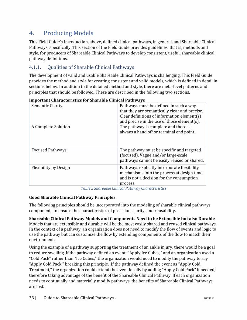
33 | Guide to Shareable Clinical Pathways - 1805211
4. Producing Models
This Field Guide’s Introduction, above, defined clinical pathways, in general, and Shareable Clinical
Pathways, specifically. This section of the Field Guide provides guidelines, that is, methods and
style, for producers of Shareable Clinical Pathways to develop consistent, useful, shareable clinical
pathway definitions.
4.1.1. Qualities of Sharable Clinical Pathways
The development of valid and usable Shareable Clinical Pathways is challenging. This Field Guide
provides the method and style for creating consistent and valid models, which is defined in detail in
sections below. In addition to the detailed method and style, there are meta-level patterns and
principles that should be followed. These are described in the following two sections.
Important Characteristics for Sharable Clinical Pathways Semantic Clarity Pathways must be defined in such a way
that they are semantically clear and precise. Clear definitions of information element(s) and precise in the use of those element(s).
A Complete Solution The pathway is complete and there is always a hand off or terminal end point.
Focused Pathways The pathway must be specific and targeted (focused). Vague and/or large-scale pathways cannot be easily reused or shared.
Flexibility by Design Pathways explicitly incorporate flexibility mechanisms into the process at design time and is not a decision for the consumption process.
Table 2 Shareable Clinical Pathway Characteristics
Good Sharable Clinical Pathway Principles
The following principles should be incorporated into the modeling of sharable clinical pathways
components to ensure the characteristics of precision, clarity, and reusability.
Shareable Clinical Pathway Models and Components Need to be Extensible but also Durable Models that are extensible and durable will be the most easily shared and reused clinical pathways. In the context of a pathway, an organization does not need to modify the flow of events and logic to use the pathway but can customize the flow by extending components of the flow to match their environment.
Using the example of a pathway supporting the treatment of an ankle injury, there would be a goal
to reduce swelling. If the pathway defined an event: “Apply Ice Cubes,” and an organization used a
“Cold Pack” rather than “Ice Cubes,” the organization would need to modify the pathway to say
“Apply Cold Pack,” breaking this principle. If the pathway defined the event as “Apply Cold
Treatment,” the organization could extend the event locally by adding “Apply Cold Pack” if needed;
therefore taking advantage of the benefit of the Shareable Clinical Pathway. If each organization
needs to continually and materially modify pathways, the benefits of Shareable Clinical Pathways
are lost.

34 | Guide to Shareable Clinical Pathways - 1805211
Shareable Clinical Pathway Model Components Need to Exhibit “Design by Contract”
Defining a component for use within a shareable pathway – there is an intrinsic need to design by
contract and as such the use of such a derived component meet the requirements for such a
contract.
Design by contract becomes particularly important in working with decision points within the
workflow. The workflow must rely on all DMN returning the same “1 to many” results regardless of
the localization of the DMN. The workflow cannot be designed in such a way that it needs to
integrate the localization of the DMN to continue processing. Take for instance a sample decision
point in a shareable workflow determining “Is ankle broken” returning two decisions “YES/NO”.
While it might make sense for a localization to have a response of “MAYBE” this breaks this
principle because the shareable workflow is expecting “YES/NO”. An appropriate design would
have the shareable workflow expect “YES/NO/MAYBE” as a result and while some localizations
would never return MAYBE the principle is upheld.
Shareable Clinical Pathway Model Components Need to Define Generalized Behaviors
Applied to the modeling of clinical pathways, events within a clinical pathway need to be designed
in such a way that their verbiage is not dependent on the context of execution, rather they are
applicable to many contexts. If, instead of “Apply Cold Treatment,” the pathway stated “Apply Cold
Treatment to Left Ankle” it would clearly limit the use of such an event to pathways dealing
specifically with left ankle injuries. This might seem trivial in nature but highlights the need to
define reusable events and decisions as a cornerstone to providing a framework of shareable
clinical pathways. If the decision or event cannot be used in multiple pathways without
modification it does not follow this principle.
Shareable Clinical Pathway Models Need to Provide a Ubiquitous and Pervasive Perspective
Pervasive computing is a natural extension of the existing computing paradigm. In the pervasive
computing vision, software agents, services, and devices are all expected to seamlessly integrate
and cooperate in support of human objectives – anticipating needs, negotiating for service, acting
on our behalf, and delivering services in an anywhere, any-time fashion. The perspective of the
Shareable Clinical Pathway needs to build upon the notion of ubiquitous and pervasive computing
to provide a complete and implementable workflow.
4.1.2. Project High-Level Best Practices
This section is not to be intended to provide full guidance about project management issues. It is
just intended to provide some of the key actions that will support the development of Shareable
Clinical Pathways. The major project management activities include:
• Performing a stakeholder analysis of the project; e.g., Responsible/Accountable/Consulted/Informed (RACI).
• Identifying one or more SMEs familiar with the clinical pathway topic who will commit to the project.
This includes SMEs that will validate the Clinical Pathway models upon completion.
• Identifying one or more Modelers familiar with BPMN, CMMN, and DMN who will create the Shareable Clinical Pathway models.
• Identifying all relevant documentation or previous modeling efforts for a clinical pathway or related medical procedure and making them available for the SMEs and Modelers to review.

35 | Guide to Shareable Clinical Pathways - 1805211
This would include relevant ontologies or glossaries.
4.1.3. Methodology for Clinical Pathway Modeling
In this section we have described the basis for a methodology that supports the development of
Shareable Clinical Pathways that are indeed sharable and to some extent automated. As with most
methodologies, there are some explicit heuristics which conforming models need to comply.
This is the general methodology for creating Shareable Clinical Pathways that is reusable,
executable, and compliant with this Field Guide:
1. Define the scope of the Shareable Clinical Pathway (which is the topic). This will help the developers of the models to stay on topic and not add extraneous activities or activities that belong in other Shareable Clinical Pathways. a. What are the different triggers of the pathway? b. What is the ending point? c. What are the goals? d. What is the context?
• Note: there are multiple approaches to a scope definition, such as: Business Model Canvas3; Value Proposition Canvas4; Inputs, Guides, Outputs, Enablers (IGOE)5; to name a few. This Field Guide does not recommend one approach over another.
2. Develop a high-level 5WH Model. a. This is the Who, What, When, Where, Why, and How (5WH) of the Clinical Pathway “(see
more information about the 5WH model below). b. Create relationships between the 5WH Model elements (e.g., Assign the Performers for the
Activities). c. This will serve as the Shareable Clinical Pathway Glossary.
3. Do Modeling. Create the first draft of the models based on content captured in the 5WH model. a. Partition HW5 Activities as appropriate b. Create the Root Case (using the name of the Shareable Clinical Pathway). c. Create Process (BPMN) and Case (CMMN) Models from the 5WH Model Activities. d. Create Decision Models (DMN) from the 5WH Model Activities. e. Create a Shareable Clinical Pathway Architectural Scope Diagram as needed.
4. Iterate on the three types of models until they are all executable. a. Utilization validation techniques, such as: review by SMEs, including model walk-throughs
and site visits; application of the method and style of this field guide; and simulation, if available.
b. Employ model decomposition as necessary to improve the organization and understandability of the set of models.
c. Synchronize the elements of the three types of models with the Clinical Pathway Glossary as they are being developed.
d. Create or utilize a Process Architecture of the healthcare organization. • Define relationships between the Clinical Pathway models and a Process Architecture.
5. Perform validation with external healthcare professionals who were not involved in the development of the Shareable Clinical Pathway. They should validate the models based on Quality & Applicability
3 https://en.wikipedia.org/wiki/Business_Model_Canvas 4 http://www.marketingteacher.com/value-proposition-canvas/ 5 https://www.brcommunity.com/articles.php?id=b634

36 | Guide to Shareable Clinical Pathways - 1805211
4.2. High-Level Modeling Best Practices
Too often, business practices assume that health delivery is being conducted within one location of
care, or within one institution, placing limitations on the processes and ultimately adversely
affecting patient care that naturally spans organizations and sites. Thus, the Shareable Clinical
Pathway Models should highlight the distributed nature of healthcare. That is, many independent
organizations are often involved in the care of an individual patient. For example, a patient may see
a doctor who is part of an independent group, then go to an imaging center for a pet scan, then go to
a lab to have blood drawn and then analyzed.
The following is an outline the best practices that should be followed to model the distributed
nature of Shareable Clinical Pathways.
1. BPMN Collaborations (a model with two or more Participants) should be used to show the communication between separate entities involved in the Shareable Clinical Pathway.
• Each Participant in a Collaboration is represented by a separate BPMN Pool. 2. In a Collaboration, one of the Pools will be the focus of the diagram and the details of the
Process within the Pool will be complete. It will be the “main” Pool. • The Processes within other Pools in the Collaboration may be undefined (i.e., the Pool is
a “black box”) or may be partially defined to show only the Tasks that send and receive messages (i.e., a “public” Process in BPMN).
• It is recommended that the external participant Pools display the public Process as it interacts with the main Pool.
• However, if the activities of the external participant are critical to the best practices defined by the Shareable Clinical Pathway, then the entire Process (all activities) should be modeled in the Pool of that participant.
3. A BPMN Choreography Diagram or Conversation Diagram is useful to isolate the interactions involved between all the participants involved in the Shareable Clinical Pathway, especially when these interactions become complex. The method and style for developing Choreography and Conversation models will be presented in a future version of this Field Guide.
4.3. Sharable Clinical Pathway Models
This Field Guide defines the content and the style for developing the knowledges artifacts that
comprise a Shareable Clinical Pathway. In this context, a Sharable Clinical Pathway contains a set of
these related models:
1. An Architectural Scope Diagram 2. A Glossary/5WH Model 3. BPMN Process Model(s) 4. CMMN Case Model(s) 5. DMN Decision Model(s)
The following sections will define the method and style for developing these models.
4.3.1. Architectural Scope Diagram
This document introduces a new diagram construct – an Architectural Scope Diagram. This diagram
was created to provide a visual representation of the breadth and relationships of the models that
make up a Shareable Clinical Pathway. Thus, the Architectural Scope Diagram is a unique, high-level
view of a Shareable Clinical Pathway; depicting its scope (size and complexity) through a graphical
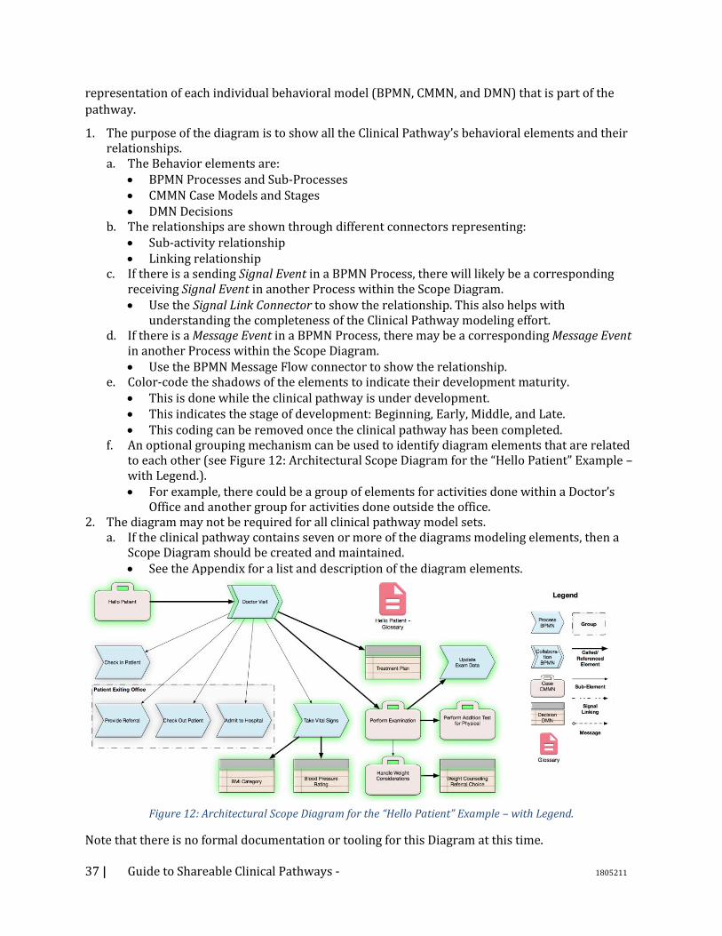
37 | Guide to Shareable Clinical Pathways - 1805211
representation of each individual behavioral model (BPMN, CMMN, and DMN) that is part of the
pathway.
1. The purpose of the diagram is to show all the Clinical Pathway’s behavioral elements and their relationships. a. The Behavior elements are:
• BPMN Processes and Sub-Processes • CMMN Case Models and Stages • DMN Decisions
b. The relationships are shown through different connectors representing: • Sub-activity relationship • Linking relationship
c. If there is a sending Signal Event in a BPMN Process, there will likely be a corresponding receiving Signal Event in another Process within the Scope Diagram. • Use the Signal Link Connector to show the relationship. This also helps with
understanding the completeness of the Clinical Pathway modeling effort. d. If there is a Message Event in a BPMN Process, there may be a corresponding Message Event
in another Process within the Scope Diagram. • Use the BPMN Message Flow connector to show the relationship.
e. Color-code the shadows of the elements to indicate their development maturity. • This is done while the clinical pathway is under development. • This indicates the stage of development: Beginning, Early, Middle, and Late. • This coding can be removed once the clinical pathway has been completed.
f. An optional grouping mechanism can be used to identify diagram elements that are related to each other (see Figure 12: Architectural Scope Diagram for the “Hello Patient” Example – with Legend.). • For example, there could be a group of elements for activities done within a Doctor’s
Office and another group for activities done outside the office. 2. The diagram may not be required for all clinical pathway model sets.
a. If the clinical pathway contains seven or more of the diagrams modeling elements, then a Scope Diagram should be created and maintained. • See the Appendix for a list and description of the diagram elements.
Figure 12: Architectural Scope Diagram for the “Hello Patient” Example – with Legend.
Note that there is no formal documentation or tooling for this Diagram at this time.
38 | Guide to Shareable Clinical Pathways - 1805211
4.3.2. Clinical Pathway Glossary/5WH Model
The 5W approach (or Who, What, When, Where, and Why), has been applied to analysis since
ancient times6. The Five Ws and one H (How) have been applied to quality stories in journalism for
more than 100 years. This is the source of the “5WH” label for the model. The approach has also
been used in the healthcare domain7.
In the context of developing a Shareable Clinical Pathway, the 5WH model is the official list of
Activities, Actors, Artifacts, Events, Systems (non-person resources), and Goals that are used in the
Models. For the purposes of Sharable Clinical Pathways, the list of 5WH items is extended to define
the relationships between the items. Which is why it is also referred to as a model.
The collection of the 5WH model items also serves as a terminology reference for the elements of
the behavioral models developed for a Clinical Pathway. This is the source of the “Glossary” label
for the model.
Many of the items that appear in the Glossary/5WH Model will appear in multiple diagrams that define the Clinical Pathway. The Glossary/5WH Model provides the naming and format of these
items as they are used in the individual models; ensuring consistency across the models, especially
for complex Clinical Pathways that could be composed of dozens of interrelated models.
Cross-Clinical Pathway Glossary/5WH Models or organizational Models can be developed to help
with consistency across a larger scope of models.
The Glossary/5WH model is the first model developed in a Sharable Clinical Pathway project.
1. The model includes these elements:
a. Activities, Actors, Artifacts, Events, Systems (non-person resources), Goals b. That is, the: How, Who, What, When, Where, Why
2. If there is a larger scope Glossary/5WH Model available, then many elements, such as Actors, Artifacts, etc., can be used in the local Glossary/5WH Model for the Clinical Pathway.
3. Glossary/5WH Model elements can be linked to external references and ontologies, as appropriate. a. If no external reference exists for a key element of the Clinical Pathway (e.g., a data artifact),
then this gap should be noted and the proper community engaged to fill that gap. 4. The relationships between the elements can be defined.
a. E.g., the standard actors who perform an activity or the required artifact inputs/outputs to an activity.
5. The Glossary/5WH Model will serve as the basis for creating the diagrams for the Clinical Pathway. It will also serve as the vocabulary/glossary of the Clinical Pathway and should be maintained throughout the project. a. To provide the most complete initial diagrams and to make the maintenance easier, it is
best to make the Glossary/5WH Model as complete as possible before starting the diagramming.
6 Edwin Carawan, "What the Laws have Prejudged: Παραγραφή and Early Issue Theory" in Cecil W. Wooten, George Alexander Kennedy, eds., The orator in action and theory in Greece and Rome, 2001. ISBN 90-04-12213-3, p. 36. 7 The Five Ws for Information Visualization with Application to Healthcare Informatics. IEEE Transactions on Visualization and Computer Graphics, Vol. 19, No. 11, November 2013.
39 | Guide to Shareable Clinical Pathways - 1805211
b. There may be substantial revision of the Clinical Pathway diagrams after they are first created from the content of the Glossary/5WH Model. Ensure that the Glossary/5WH Model is maintained throughout the development of the Clinical Pathway Model.
The next few sections define the style and modeling conventions for the types of elements within a
Glossary/5WH Model. The Glossary/5WH model can be created with various tools, including Excel.
The images provided in this Field Guide include examples with Excel and with another vendor
implementations of the Glossary/5WH model.
It should be noted that the development of the 5WH model will continue throughout the
development of the Shareable Clinical Pathway. There will be an early version of the 5WH model
created while doing the initial discovery and analysis of the Clinical Pathway information and
through the interviews of the SMEs. When the three types of diagrams (BPMN, CMMN, and DMN)
are developed, then the structure and organization of the 5WH model could be significantly
modified. The sections below describe the 5WH elements and how the elements of the three
diagrams will impact their format.
Cross-Clinical Pathways Glossary 1. If there is a Cross-Clinical Pathway Glossary, then items in the larger Glossary that match items
in the local, Clinical Pathway Glossary should be used in the Clinical Pathway Glossary. 2. Once the Clinical Pathway has been completed, the local Glossary for the Clinical Pathway
should be reconciled with the Cross-Clinical Pathway Glossary. Activities Activities represent the “how” aspect of the Clinical Pathway. This is the work and/or general behaviors that are performed for the Clinical Pathway.
1. The work of a Shareable Clinical Pathway will usually be divided into multiple 5WH Activity elements. These Activities can be hierarchical decomposed and can be linked together.
a. Each Activity element represents a separate cohesive portion of work, which will be defined with a BPMN Process or a CMMN Case. • The highest-level activity will be a CMMN Case Model. See more on this below. • An Activity element will have a list of items that represent the Tasks and Sub-Structure
elements of that BPMN Process or CMMN Case. b. It is up to the business analyst to determine which Activity elements will be modeled with a
BPMN Process and which will be modeled with a CMMN Case. An SME should be able to verify that a group of activity items are performed in a general sequence or in an unstructured manner. • The figure below displays two Activities for the Hello Patient example. The Activity on
the left was used to generate a CMMN model and the Activity on the right was used to generate a BPMN model. The differences between the two Activities are not easily apparent until the diagrams are created from their content.
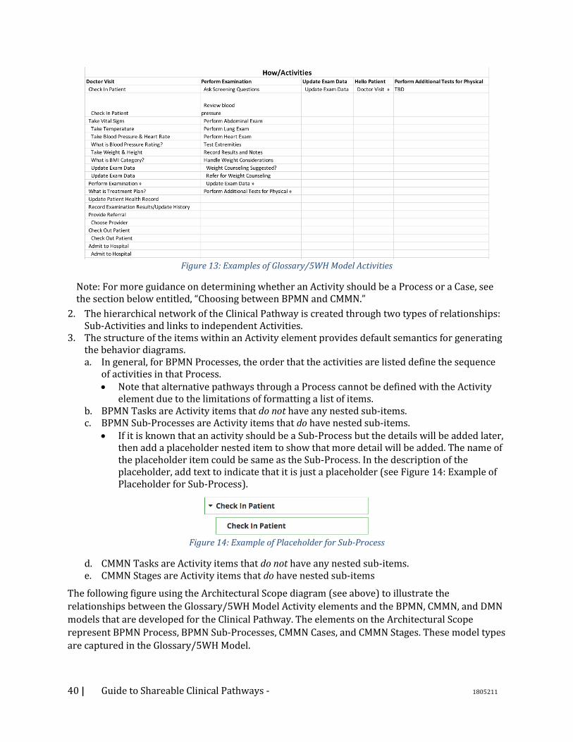
40 | Guide to Shareable Clinical Pathways - 1805211
Figure 13: Examples of Glossary/5WH Model Activities
Note: For more guidance on determining whether an Activity should be a Process or a Case, see the section below entitled, “Choosing between BPMN and CMMN.”
2. The hierarchical network of the Clinical Pathway is created through two types of relationships: Sub-Activities and links to independent Activities.
3. The structure of the items within an Activity element provides default semantics for generating the behavior diagrams. a. In general, for BPMN Processes, the order that the activities are listed define the sequence
of activities in that Process. • Note that alternative pathways through a Process cannot be defined with the Activity
element due to the limitations of formatting a list of items. b. BPMN Tasks are Activity items that do not have any nested sub-items. c. BPMN Sub-Processes are Activity items that do have nested sub-items.
• If it is known that an activity should be a Sub-Process but the details will be added later, then add a placeholder nested item to show that more detail will be added. The name of the placeholder item could be same as the Sub-Process. In the description of the placeholder, add text to indicate that it is just a placeholder (see Figure 14: Example of Placeholder for Sub-Process).
Figure 14: Example of Placeholder for Sub-Process
d. CMMN Tasks are Activity items that do not have any nested sub-items. e. CMMN Stages are Activity items that do have nested sub-items
The following figure using the Architectural Scope diagram (see above) to illustrate the
relationships between the Glossary/5WH Model Activity elements and the BPMN, CMMN, and DMN
models that are developed for the Clinical Pathway. The elements on the Architectural Scope
represent BPMN Process, BPMN Sub-Processes, CMMN Cases, and CMMN Stages. These model types
are captured in the Glossary/5WH Model.
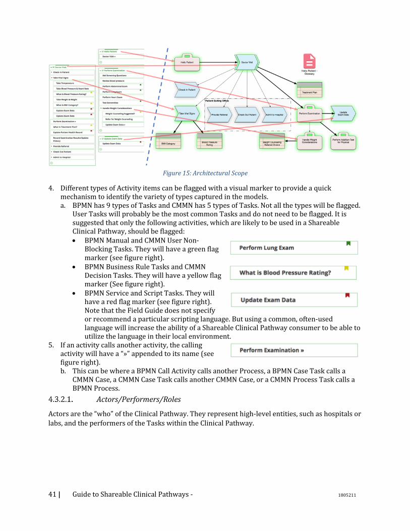
41 | Guide to Shareable Clinical Pathways - 1805211
Figure 15: Architectural Scope
4. Different types of Activity items can be flagged with a visual marker to provide a quick mechanism to identify the variety of types captured in the models. a. BPMN has 9 types of Tasks and CMMN has 5 types of Tasks. Not all the types will be flagged.
User Tasks will probably be the most common Tasks and do not need to be flagged. It is suggested that only the following activities, which are likely to be used in a Shareable Clinical Pathway, should be flagged: • BPMN Manual and CMMN User Non-
Blocking Tasks. They will have a green flag marker (see figure right).
• BPMN Business Rule Tasks and CMMN Decision Tasks. They will have a yellow flag marker (See figure right).
• BPMN Service and Script Tasks. They will have a red flag marker (see figure right). Note that the Field Guide does not specify or recommend a particular scripting language. But using a common, often-used language will increase the ability of a Shareable Clinical Pathway consumer to be able to utilize the language in their local environment.
5. If an activity calls another activity, the calling activity will have a “»” appended to its name (see figure right). b. This can be where a BPMN Call Activity calls another Process, a BPMN Case Task calls a
CMMN Case, a CMMN Case Task calls another CMMN Case, or a CMMN Process Task calls a BPMN Process.
Actors/Performers/Roles
Actors are the “who” of the Clinical Pathway. They represent high-level entities, such as hospitals or
labs, and the performers of the Tasks within the Clinical Pathway.
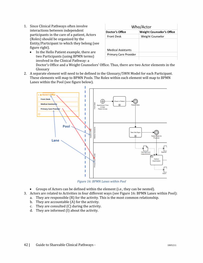
42 | Guide to Shareable Clinical Pathways - 1805211
1. Since Clinical Pathways often involve interactions between independent participants in the care of a patient, Actors (Roles) should be organized by the Entity/Participant to which they belong (see figure right). • In the Hello Patient example, there are
two Participants (using BPMN terms) involved in the Clinical Pathway: a Doctor’s Office and a Weight Counselors’ Office. Thus, there are two Actor elements in the Glossary
2. A separate element will need to be defined in the Glossary/5WH Model for each Participant. These elements will map to BPMN Pools. The Roles within each element will map to BPMN Lanes within the Pool (see figure below).
Figure 16: BPMN Lanes within Pool
• Groups of Actors can be defined within the element (i.e., they can be nested). 3. Actors are related to Activities in four different ways (see Figure 16: BPMN Lanes within Pool):
a. They are responsible (R) for the activity. This is the most common relationship. b. They are accountable (A) for the activity. c. They are consulted (C) during the activity. d. They are informed (I) about the activity.
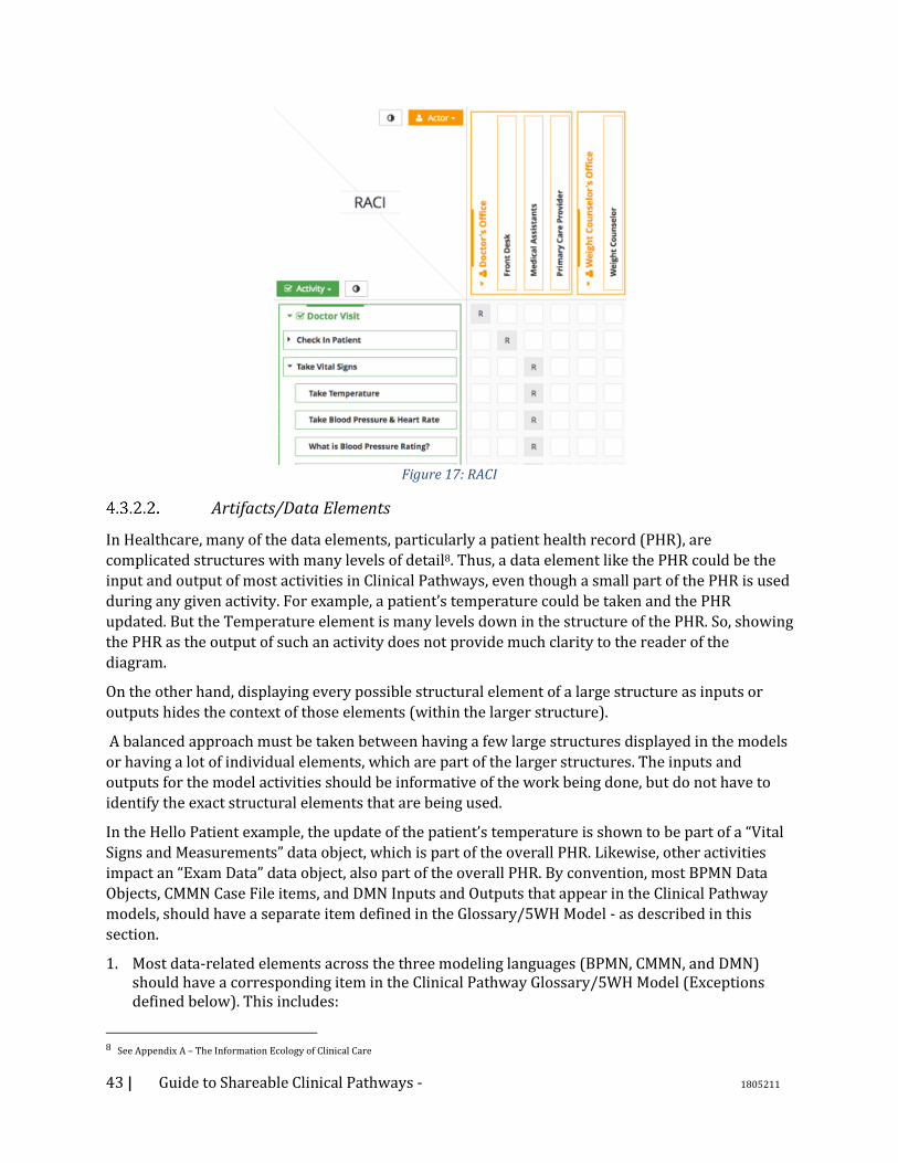
43 | Guide to Shareable Clinical Pathways - 1805211
Figure 17: RACI
Artifacts/Data Elements
In Healthcare, many of the data elements, particularly a patient health record (PHR), are
complicated structures with many levels of detail8. Thus, a data element like the PHR could be the
input and output of most activities in Clinical Pathways, even though a small part of the PHR is used
during any given activity. For example, a patient’s temperature could be taken and the PHR
updated. But the Temperature element is many levels down in the structure of the PHR. So, showing
the PHR as the output of such an activity does not provide much clarity to the reader of the
diagram.
On the other hand, displaying every possible structural element of a large structure as inputs or
outputs hides the context of those elements (within the larger structure).
A balanced approach must be taken between having a few large structures displayed in the models
or having a lot of individual elements, which are part of the larger structures. The inputs and
outputs for the model activities should be informative of the work being done, but do not have to
identify the exact structural elements that are being used.
In the Hello Patient example, the update of the patient’s temperature is shown to be part of a “Vital
Signs and Measurements” data object, which is part of the overall PHR. Likewise, other activities
impact an “Exam Data” data object, also part of the overall PHR. By convention, most BPMN Data
Objects, CMMN Case File items, and DMN Inputs and Outputs that appear in the Clinical Pathway
models, should have a separate item defined in the Glossary/5WH Model - as described in this
section.
1. Most data-related elements across the three modeling languages (BPMN, CMMN, and DMN) should have a corresponding item in the Clinical Pathway Glossary/5WH Model (Exceptions defined below). This includes:
8 See Appendix A – The Information Ecology of Clinical Care
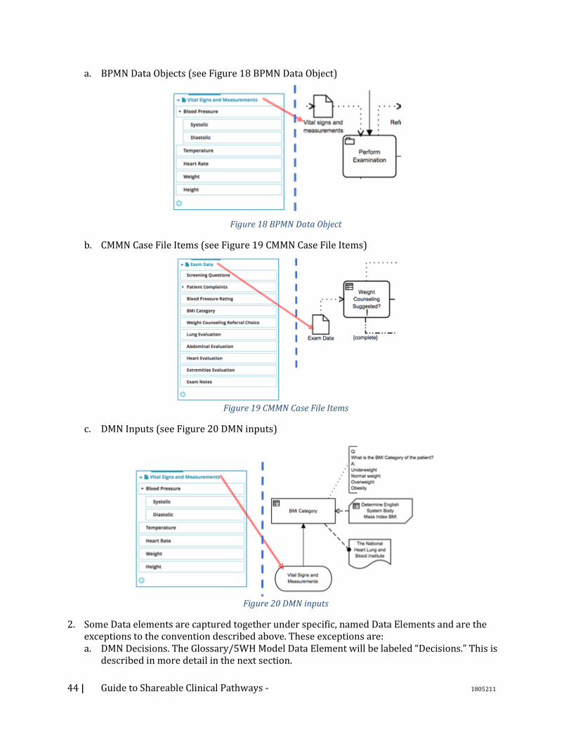
44 | Guide to Shareable Clinical Pathways - 1805211
a. BPMN Data Objects (see Figure 18 BPMN Data Object)
Figure 18 BPMN Data Object
b. CMMN Case File Items (see Figure 19 CMMN Case File Items)
Figure 19 CMMN Case File Items
c. DMN Inputs (see Figure 20 DMN inputs)
Figure 20 DMN inputs
2. Some Data elements are captured together under specific, named Data Elements and are the exceptions to the convention described above. These exceptions are: a. DMN Decisions. The Glossary/5WH Model Data Element will be labeled “Decisions.” This is
described in more detail in the next section.
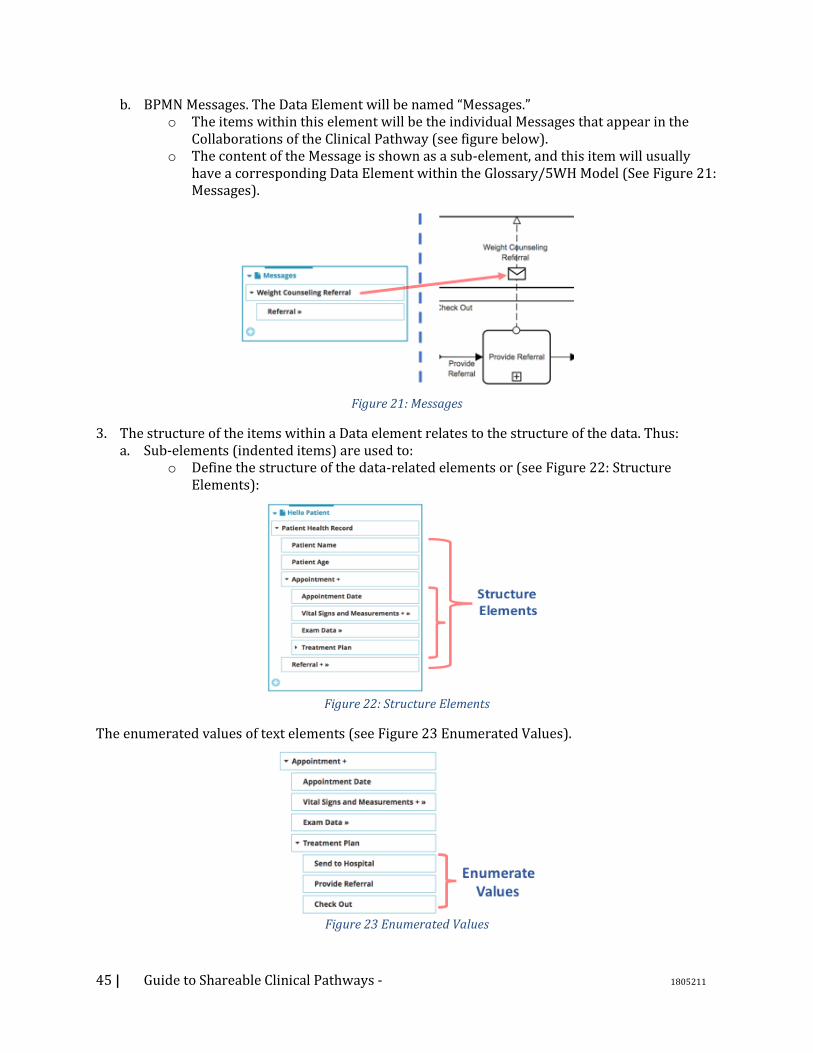
45 | Guide to Shareable Clinical Pathways - 1805211
b. BPMN Messages. The Data Element will be named “Messages.” o The items within this element will be the individual Messages that appear in the
Collaborations of the Clinical Pathway (see figure below). o The content of the Message is shown as a sub-element, and this item will usually
have a corresponding Data Element within the Glossary/5WH Model (See Figure 21: Messages).
Figure 21: Messages
3. The structure of the items within a Data element relates to the structure of the data. Thus: a. Sub-elements (indented items) are used to:
o Define the structure of the data-related elements or (see Figure 22: Structure Elements):
Figure 22: Structure Elements
The enumerated values of text elements (see Figure 23 Enumerated Values).
Figure 23 Enumerated Values
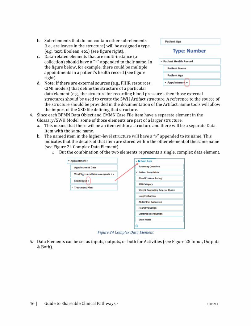
46 | Guide to Shareable Clinical Pathways - 1805211
b. Sub-elements that do not contain other sub-elements (i.e., are leaves in the structure) will be assigned a type (e.g., text, Boolean, etc.) (see figure right).
c. Data-related elements that are multi-instance (a collection) should have a “+” appended to their name. In the figure below, for example, there could be multiple appointments in a patient’s health record (see figure right).
d. Note: If there are external sources (e.g., FHIR resources, CIMI models) that define the structure of a particular data element (e.g., the structure for recording blood pressure), then those external structures should be used to create the 5WH Artifact structure. A reference to the source of the structure should be provided in the documentation of the Artifact. Some tools will allow the import of the XSD file defining that structure.
4. Since each BPMN Data Object and CMMN Case File item have a separate element in the Glossary/5WH Model, some of those elements are part of a larger structure. a. This means that there will be an item within a structure and there will be a separate Data
Item with the same name. b. The named item in the higher-level structure will have a “»” appended to its name. This
indicates that the details of that item are stored within the other element of the same name (see Figure 24 Complex Data Element).
o But the combination of the two elements represents a single, complex data element.
Figure 24 Complex Data Element
5. Data Elements can be set as inputs, outputs, or both for Activities (see Figure 25 Input, Outputs & Both).
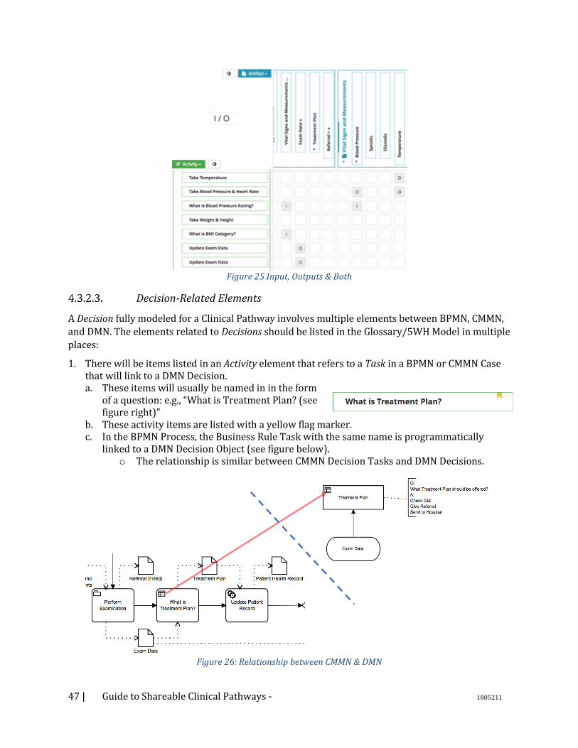
47 | Guide to Shareable Clinical Pathways - 1805211
Figure 25 Input, Outputs & Both
Decision-Related Elements
A Decision fully modeled for a Clinical Pathway involves multiple elements between BPMN, CMMN,
and DMN. The elements related to Decisions should be listed in the Glossary/5WH Model in multiple
places:
1. There will be items listed in an Activity element that refers to a Task in a BPMN or CMMN Case that will link to a DMN Decision. a. These items will usually be named in in the form
of a question: e.g., “What is Treatment Plan? (see figure right)”
b. These activity items are listed with a yellow flag marker. c. In the BPMN Process, the Business Rule Task with the same name is programmatically
linked to a DMN Decision Object (see figure below). o The relationship is similar between CMMN Decision Tasks and DMN Decisions.
Figure 26: Relationship between CMMN & DMN
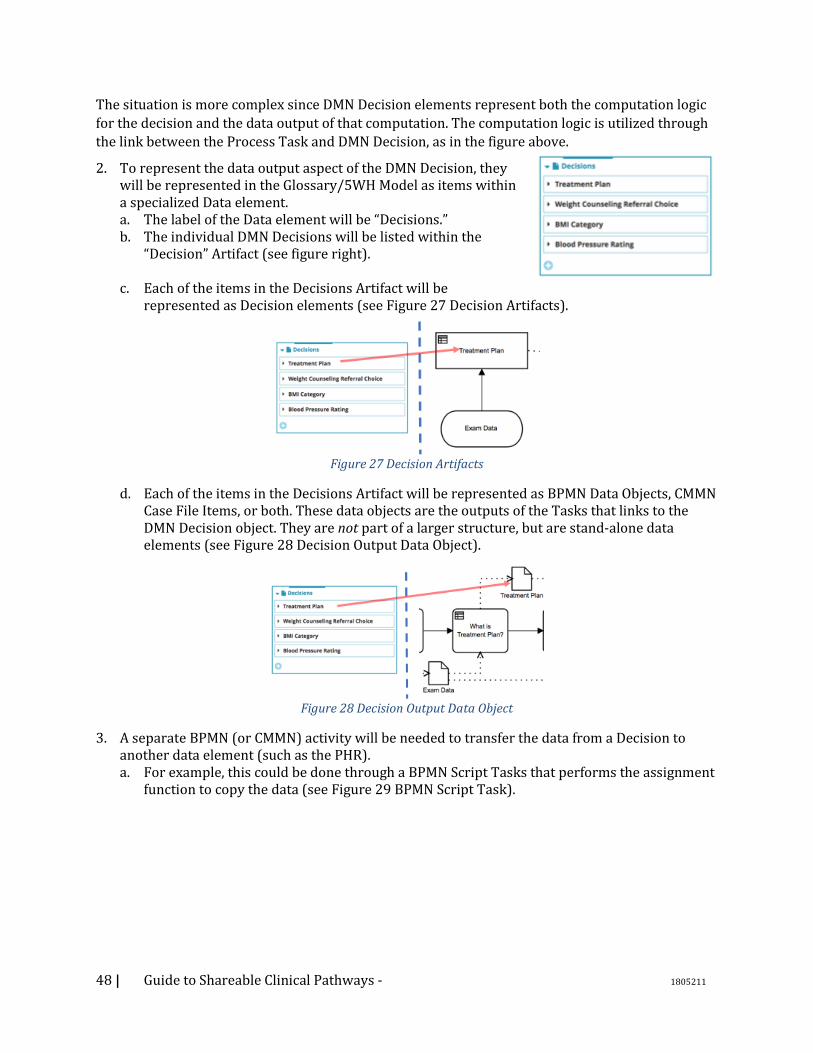
48 | Guide to Shareable Clinical Pathways - 1805211
The situation is more complex since DMN Decision elements represent both the computation logic
for the decision and the data output of that computation. The computation logic is utilized through
the link between the Process Task and DMN Decision, as in the figure above.
2. To represent the data output aspect of the DMN Decision, they will be represented in the Glossary/5WH Model as items within a specialized Data element. a. The label of the Data element will be “Decisions.” b. The individual DMN Decisions will be listed within the
“Decision” Artifact (see figure right).
c. Each of the items in the Decisions Artifact will be represented as Decision elements (see Figure 27 Decision Artifacts).
Figure 27 Decision Artifacts
d. Each of the items in the Decisions Artifact will be represented as BPMN Data Objects, CMMN Case File Items, or both. These data objects are the outputs of the Tasks that links to the DMN Decision object. They are not part of a larger structure, but are stand-alone data elements (see Figure 28 Decision Output Data Object).
Figure 28 Decision Output Data Object
3. A separate BPMN (or CMMN) activity will be needed to transfer the data from a Decision to another data element (such as the PHR). a. For example, this could be done through a BPMN Script Tasks that performs the assignment
function to copy the data (see Figure 29 BPMN Script Task).
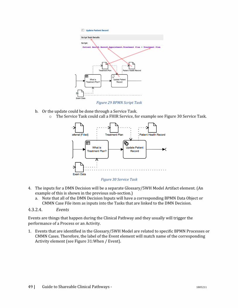
49 | Guide to Shareable Clinical Pathways - 1805211
Figure 29 BPMN Script Task
b. Or the update could be done through a Service Task. o The Service Task could call a FHIR Service, for example see Figure 30 Service Task.
Figure 30 Service Task
4. The inputs for a DMN Decision will be a separate Glossary/5WH Model Artifact element. (An example of this is shown in the previous sub-section.) a. Note that all of the DMN Decision Inputs will have a corresponding BPMN Data Object or
CMMN Case File item as inputs into the Tasks that are linked to the DMN Decision.
Events
Events are things that happen during the Clinical Pathway and they usually will trigger the
performance of a Process or an Activity.
1. Events that are identified in the Glossary/5WH Model are related to specific BPMN Processes or CMMN Cases. Therefore, the label of the Event element will match name of the corresponding Activity element (see Figure 31:When / Event).
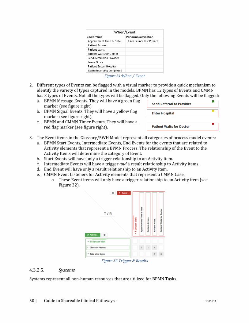
50 | Guide to Shareable Clinical Pathways - 1805211
Figure 31:When / Event
2. Different types of Events can be flagged with a visual marker to provide a quick mechanism to identify the variety of types captured in the models. BPMN has 12 types of Events and CMMN has 3 types of Events. Not all the types will be flagged. Only the following Events will be flagged: a. BPMN Message Events. They will have a green flag
marker (see figure right). b. BPMN Signal Events. They will have a yellow flag
marker (see figure right). c. BPMN and CMMN Timer Events. They will have a
red flag marker (see figure right).
3. The Event items in the Glossary/5WH Model represent all categories of process model events: a. BPMN Start Events, Intermediate Events, End Events for the events that are related to
Activity elements that represent a BPMN Process. The relationship of the Event to the Activity Items will determine the category of Event.
b. Start Events will have only a trigger relationship to an Activity item. c. Intermediate Events will have a trigger and a result relationship to Activity items. d. End Event will have only a result relationship to an Activity item. e. CMMN Event Listeners for Activity elements that represent a CMMN Case.
o These Event items will only have a trigger relationship to an Activity item (see Figure 32).
Figure 32 Trigger & Results
Systems
Systems represent all non-human resources that are utilized for BPMN Tasks.
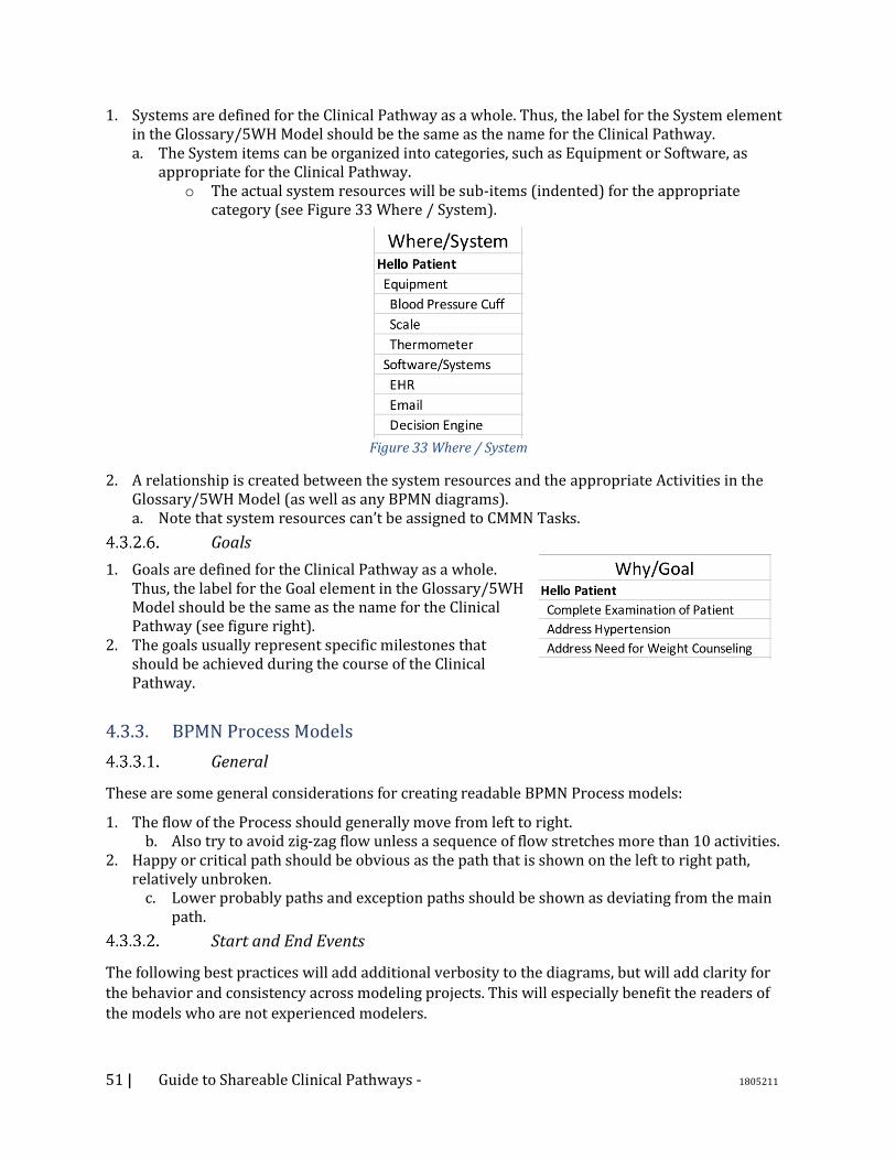
51 | Guide to Shareable Clinical Pathways - 1805211
1. Systems are defined for the Clinical Pathway as a whole. Thus, the label for the System element in the Glossary/5WH Model should be the same as the name for the Clinical Pathway. a. The System items can be organized into categories, such as Equipment or Software, as
appropriate for the Clinical Pathway. o The actual system resources will be sub-items (indented) for the appropriate
category (see Figure 33 Where / System).
Figure 33 Where / System
2. A relationship is created between the system resources and the appropriate Activities in the Glossary/5WH Model (as well as any BPMN diagrams). a. Note that system resources can’t be assigned to CMMN Tasks.
Goals
1. Goals are defined for the Clinical Pathway as a whole. Thus, the label for the Goal element in the Glossary/5WH Model should be the same as the name for the Clinical Pathway (see figure right).
2. The goals usually represent specific milestones that should be achieved during the course of the Clinical Pathway.
4.3.3. BPMN Process Models
General
These are some general considerations for creating readable BPMN Process models:
1. The flow of the Process should generally move from left to right. b. Also try to avoid zig-zag flow unless a sequence of flow stretches more than 10 activities.
2. Happy or critical path should be obvious as the path that is shown on the left to right path, relatively unbroken.
c. Lower probably paths and exception paths should be shown as deviating from the main path.
Start and End Events
The following best practices will add additional verbosity to the diagrams, but will add clarity for
the behavior and consistency across modeling projects. This will especially benefit the readers of
the models who are not experienced modelers.

52 | Guide to Shareable Clinical Pathways - 1805211
1. Always include a Start Event for a Process level. • This Event should be named.
2. Always include an End Event for each path of a Process level. • This Event should be named and, when appropriate,
represent an “end state.” 3. Exception: if the modeler wants to show a few parallel
activities without the overhead of the starting and ending Parallel Gateways and all the necessary Sequence Flows, then a “Parallel Box” can be used. This is a simple Sub-Process where there is no Start or End Events, or no Gateways or Sequence Flows. There would only be a few, disconnected activities. The behavior is the same as using matching Parallel Gateways with the activities connected between, but without the visual clutter.
Using Activities
1. Set the Task type for the Tasks in the Clinical Pathway. a. The majority will be User Tasks, but also be sure to document the Manual, Service, Business
Rule, Script, and any type that is relevant for the Process (see Figure 34 Using Activities).
Figure 34 Using Activities
o None (Abstract) Tasks are used only in the early stages of the modeling and are placeholders for the detailed Task information.
2. The use of expanded or collapsed Sub-Processes is a choice of the Clinical Pathway producer. • Collapsed Sub-Processes were used in the Hello Patient example.
3. Some Sub-Processes will initially have placeholder tasks, which were added just to mark that more detail will be added later. In this case, the name of the Sub-Process and the placeholder Task within the Sub-Process will be the same. Also, a Text Annotation should be attached to the Task describing the situation of the Task as a placeholder (see Figure 35 Text Annotation).
Figure 35 Text Annotation
Using Gateways
1. Use matching splitting and merging Gateways when possible.

53 | Guide to Shareable Clinical Pathways - 1805211
a. BPMN does not require splitting Parallel Gateways except for a few situations. However, the use of a splitting Parallel Gateway will make the behavior of the Process easier to understand (See Figure 36 Parallel Gateway).
Figure 36 Parallel Gateway
b. Use matching splitting and merging Exclusive Gateways. c. Use matching splitting and merging Inclusive Gateways. d. Event Gateways should be merged with Exclusive Gateways.
2. Don’t use matching Gateways in situations that would make the diagram unnecessarily complex (e.g., when the paths are in separate Lanes). a. Or when you have distinct outcomes across the paths (see Figure 37 Distinct Outcomes).
Figure 37 Distinct Outcomes
Using Event Sub-Processes
1. If there is a Process that has a well-defined structure (e.g., it is should be a Process rather than a Case), but it has a couple of activities that are not connected to the base structure, then Event Sub-Processes should be used, rather than converting the model to a Case diagram just to handle a couple of disconnected activities (see Figure 38 An Example of an Event Sub-Process).
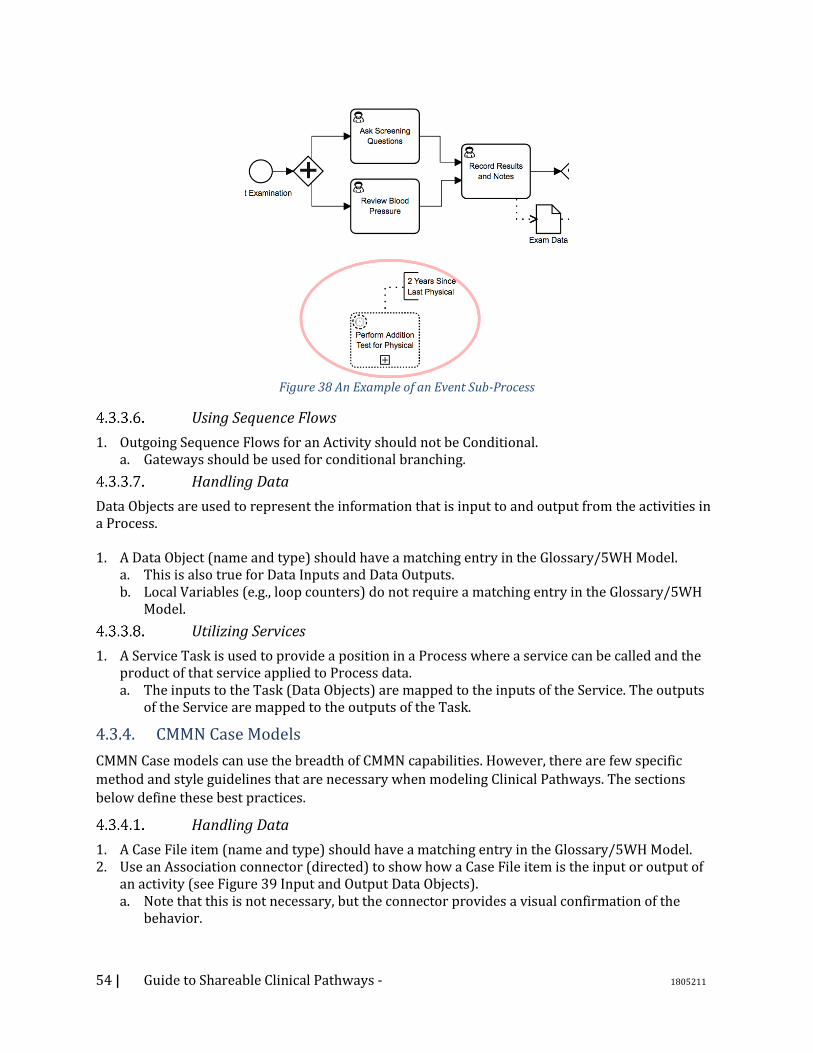
54 | Guide to Shareable Clinical Pathways - 1805211
Figure 38 An Example of an Event Sub-Process
Using Sequence Flows
1. Outgoing Sequence Flows for an Activity should not be Conditional. a. Gateways should be used for conditional branching.
Handling Data
Data Objects are used to represent the information that is input to and output from the activities in a Process. 1. A Data Object (name and type) should have a matching entry in the Glossary/5WH Model.
a. This is also true for Data Inputs and Data Outputs. b. Local Variables (e.g., loop counters) do not require a matching entry in the Glossary/5WH
Model.
Utilizing Services
1. A Service Task is used to provide a position in a Process where a service can be called and the product of that service applied to Process data. a. The inputs to the Task (Data Objects) are mapped to the inputs of the Service. The outputs
of the Service are mapped to the outputs of the Task.
4.3.4. CMMN Case Models
CMMN Case models can use the breadth of CMMN capabilities. However, there are few specific
method and style guidelines that are necessary when modeling Clinical Pathways. The sections
below define these best practices.
Handling Data
1. A Case File item (name and type) should have a matching entry in the Glossary/5WH Model. 2. Use an Association connector (directed) to show how a Case File item is the input or output of
an activity (see Figure 39 Input and Output Data Objects). a. Note that this is not necessary, but the connector provides a visual confirmation of the
behavior.
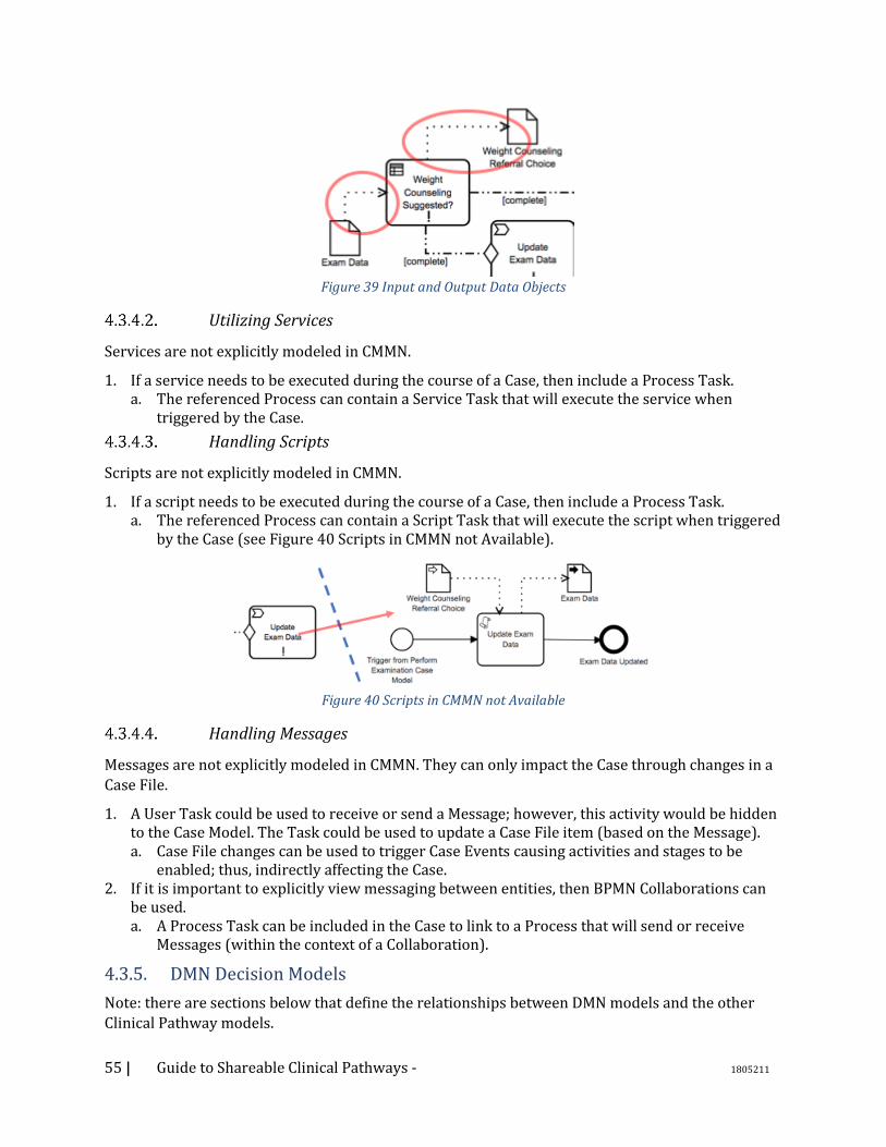
55 | Guide to Shareable Clinical Pathways - 1805211
Figure 39 Input and Output Data Objects
Utilizing Services
Services are not explicitly modeled in CMMN.
1. If a service needs to be executed during the course of a Case, then include a Process Task. a. The referenced Process can contain a Service Task that will execute the service when
triggered by the Case.
Handling Scripts
Scripts are not explicitly modeled in CMMN.
1. If a script needs to be executed during the course of a Case, then include a Process Task. a. The referenced Process can contain a Script Task that will execute the script when triggered
by the Case (see Figure 40 Scripts in CMMN not Available).
Figure 40 Scripts in CMMN not Available
Handling Messages
Messages are not explicitly modeled in CMMN. They can only impact the Case through changes in a
Case File.
1. A User Task could be used to receive or send a Message; however, this activity would be hidden to the Case Model. The Task could be used to update a Case File item (based on the Message). a. Case File changes can be used to trigger Case Events causing activities and stages to be
enabled; thus, indirectly affecting the Case. 2. If it is important to explicitly view messaging between entities, then BPMN Collaborations can
be used. a. A Process Task can be included in the Case to link to a Process that will send or receive
Messages (within the context of a Collaboration).
4.3.5. DMN Decision Models
Note: there are sections below that define the relationships between DMN models and the other
Clinical Pathway models.

56 | Guide to Shareable Clinical Pathways - 1805211
1. In general, a DMN Decision represents a question with a set of possible answers. An annotation can be used in the DMN model to document the question and answers for each Decision Object so that the reader of the diagram can understand the nature of the Decision (see Figure 41 Annotations are Used to Document Scope of Decision).
Figure 41 Annotations are Used to Document Scope of Decision
a. The same question and answers can also be used as part of the definition of the DMN Decision. It is recommended that the initial development of the Decision start with the question and answers prior to actual decision logic.
2. The name of the DMN Decision object should match the name of the output of the Decision (e.g., “BMI Category”). • The Decision name should also match the Data Object output of the BPMN Business Rule
Task or the updated Case File item for the CMMN Decision Task. 3. Inputs (name and type) should have matching Data elements in the Glossary/5WH Model.
• There will also be a matching BPMN Data Object or CMMN Case Item, or both. 4. Outputs should have matching Data element items in the Glossary/5WH Model.
• There will also be a matching BPMN Data Object or CMMN Case Item, or both. 5. If the Decision logic being called from BPMN or CMMN is separated into a chain of DMN
Decision objects, then all Input Objects in that chain must be inputs into the Process Task. a. For example, in the figure below, if BPMN links to the “Weight Counseling Referral Choice”
Decision, then Input object (Exam Data) to that Decision and the Input Object (Vital Signs and Measurements) to the Decision that feeds into the linked Decision must be included as inputs into the BPMN Business Rule Task.
o Note that the Hello Patient example used a different structure for the Decision in the Figure 42 Mapping Between BPMN Elements and DMN Elements.

57 | Guide to Shareable Clinical Pathways - 1805211
Figure 42 Mapping Between BPMN Elements and DMN Elements
6. When available, provide the external knowledge source that is used to create the Decision Logic. a. For example, in the Hello Patient example below, the BMI categories are defined by the
National Heart Lung and Blood Institute. A link is provided to the Website page that defines the categories.
Figure 43 Link to Knowledge Model
4.4. Relationships Between Clinical Pathway Models
4.4.1. Choosing between BPMN and CMMN
BPMN and CMMN have some overlapping capabilities. Thus, it is not always obvious which model is
appropriate for each situation. In fact, there may be sets of activities that can be modeled in either
modeling language.
One thing to consider is that the choice between BPMN and CMMN is not necessarily permanent.
During the iterative development of a Clinical Pathway, it may be necessary to change one model
into another. Thus, the choice between the two should not be over-thought. The following figure provides a guideline for making the choice between BPMN and CMMN.
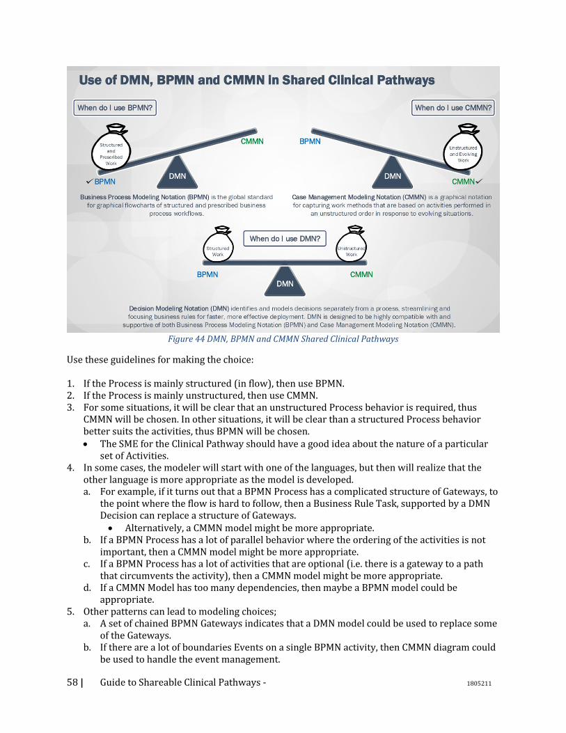
58 | Guide to Shareable Clinical Pathways - 1805211
Figure 44 DMN, BPMN and CMMN Shared Clinical Pathways
Use these guidelines for making the choice: 1. If the Process is mainly structured (in flow), then use BPMN. 2. If the Process is mainly unstructured, then use CMMN. 3. For some situations, it will be clear that an unstructured Process behavior is required, thus
CMMN will be chosen. In other situations, it will be clear than a structured Process behavior better suits the activities, thus BPMN will be chosen. • The SME for the Clinical Pathway should have a good idea about the nature of a particular
set of Activities. 4. In some cases, the modeler will start with one of the languages, but then will realize that the
other language is more appropriate as the model is developed. a. For example, if it turns out that a BPMN Process has a complicated structure of Gateways, to
the point where the flow is hard to follow, then a Business Rule Task, supported by a DMN Decision can replace a structure of Gateways. • Alternatively, a CMMN model might be more appropriate.
b. If a BPMN Process has a lot of parallel behavior where the ordering of the activities is not important, then a CMMN model might be more appropriate.
c. If a BPMN Process has a lot of activities that are optional (i.e. there is a gateway to a path that circumvents the activity), then a CMMN model might be more appropriate.
d. If a CMMN Model has too many dependencies, then maybe a BPMN model could be appropriate.
5. Other patterns can lead to modeling choices; a. A set of chained BPMN Gateways indicates that a DMN model could be used to replace some
of the Gateways. b. If there are a lot of boundaries Events on a single BPMN activity, then CMMN diagram could
be used to handle the event management.
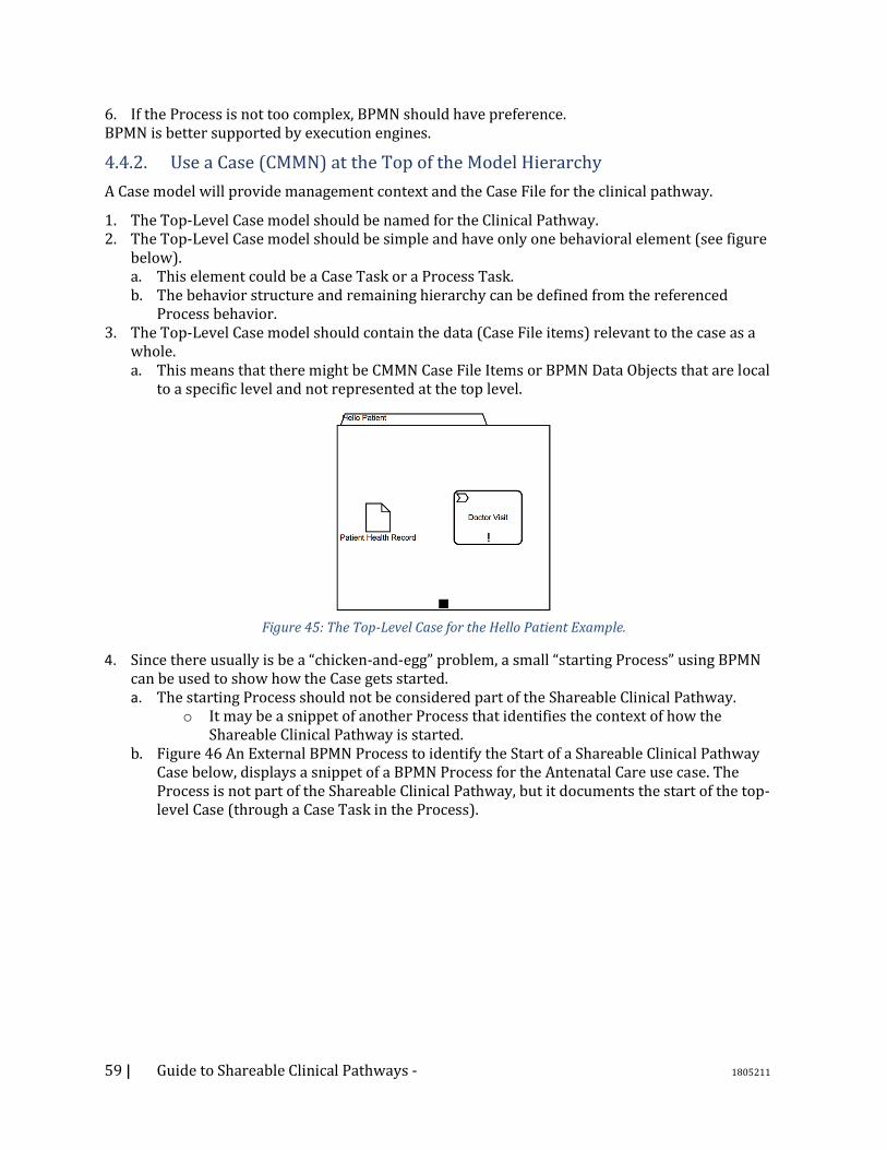
59 | Guide to Shareable Clinical Pathways - 1805211
6. If the Process is not too complex, BPMN should have preference. BPMN is better supported by execution engines.
4.4.2. Use a Case (CMMN) at the Top of the Model Hierarchy
A Case model will provide management context and the Case File for the clinical pathway.
1. The Top-Level Case model should be named for the Clinical Pathway. 2. The Top-Level Case model should be simple and have only one behavioral element (see figure
below). a. This element could be a Case Task or a Process Task. b. The behavior structure and remaining hierarchy can be defined from the referenced
Process behavior. 3. The Top-Level Case model should contain the data (Case File items) relevant to the case as a
whole. a. This means that there might be CMMN Case File Items or BPMN Data Objects that are local
to a specific level and not represented at the top level.
Figure 45: The Top-Level Case for the Hello Patient Example.
4. Since there usually is be a “chicken-and-egg” problem, a small “starting Process” using BPMN can be used to show how the Case gets started. a. The starting Process should not be considered part of the Shareable Clinical Pathway.
o It may be a snippet of another Process that identifies the context of how the Shareable Clinical Pathway is started.
b. Figure 46 An External BPMN Process to identify the Start of a Shareable Clinical Pathway Case below, displays a snippet of a BPMN Process for the Antenatal Care use case. The Process is not part of the Shareable Clinical Pathway, but it documents the start of the top-level Case (through a Case Task in the Process).
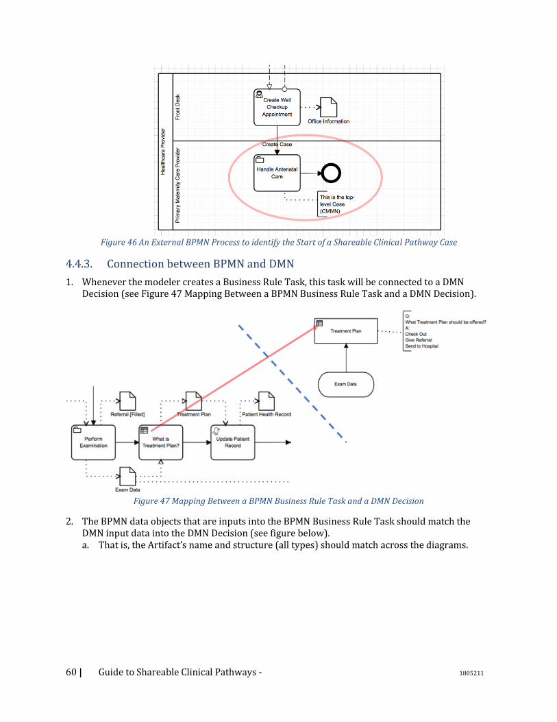
60 | Guide to Shareable Clinical Pathways - 1805211
Figure 46 An External BPMN Process to identify the Start of a Shareable Clinical Pathway Case
4.4.3. Connection between BPMN and DMN
1. Whenever the modeler creates a Business Rule Task, this task will be connected to a DMN Decision (see Figure 47 Mapping Between a BPMN Business Rule Task and a DMN Decision).
Figure 47 Mapping Between a BPMN Business Rule Task and a DMN Decision
2. The BPMN data objects that are inputs into the BPMN Business Rule Task should match the DMN input data into the DMN Decision (see figure below). a. That is, the Artifact’s name and structure (all types) should match across the diagrams.
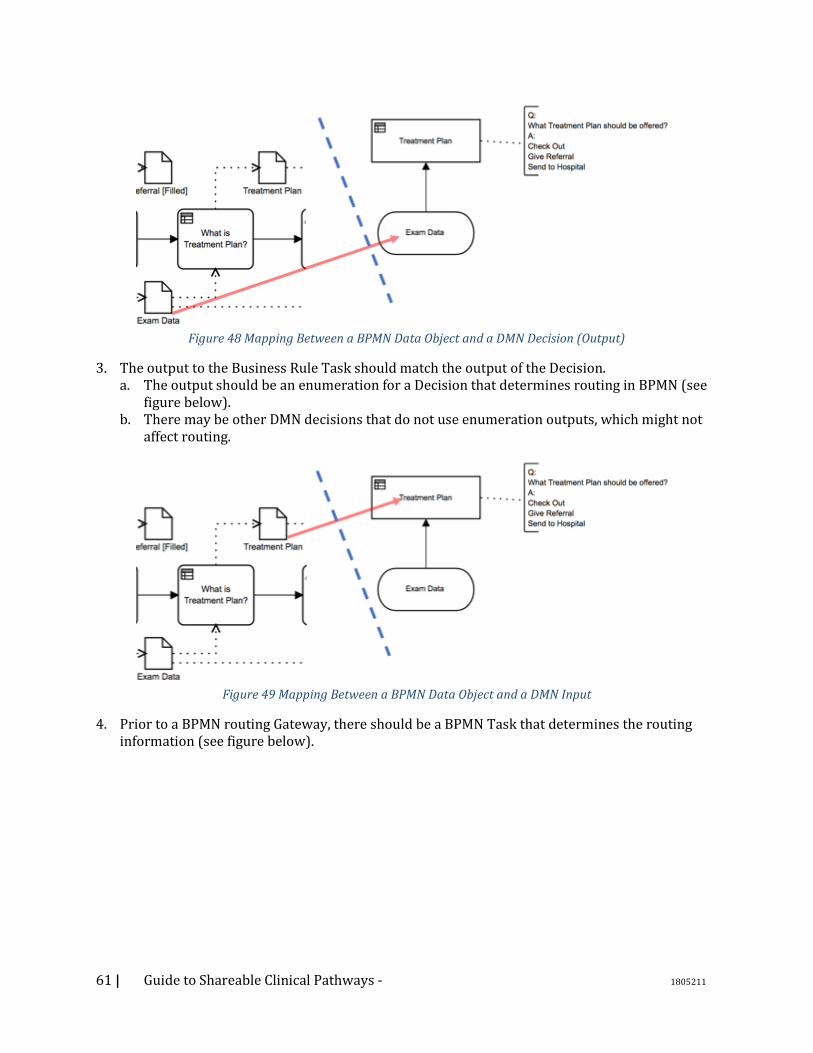
61 | Guide to Shareable Clinical Pathways - 1805211
Figure 48 Mapping Between a BPMN Data Object and a DMN Decision (Output)
3. The output to the Business Rule Task should match the output of the Decision. a. The output should be an enumeration for a Decision that determines routing in BPMN (see
figure below). b. There may be other DMN decisions that do not use enumeration outputs, which might not
affect routing.
Figure 49 Mapping Between a BPMN Data Object and a DMN Input
4. Prior to a BPMN routing Gateway, there should be a BPMN Task that determines the routing information (see figure below).

62 | Guide to Shareable Clinical Pathways - 1805211
Figure 50 Relationship Between a BPMN Business Rule Task and an Exclusive Gateway
a. This Task should provide the enumeration that determines the routing for the Gateway. o Note that there might be other BPMN elements in between the decision-related Task
and the Gateway that routes based on that Task (as in the figure above). b. This BPMN Task that provides the routing information could be Business Rule Task, User
Task, Script Task, and Service Task. o Most of the time it will be a Business Rule Task.
c. The routing Gateway should be Exclusive or Inclusive. o The Gateway should not be Parallel, Event-Based or Complex. o For Inclusive Gateways, the output of the Decision should support one to many
results. 5. The conditions and labels defined for the BPMN routing Gateway’s outgoing Sequence Flows
should match the enumerated values of the output of the BPMN Business Rule Task that came from the DMN Decision (see next two figures).
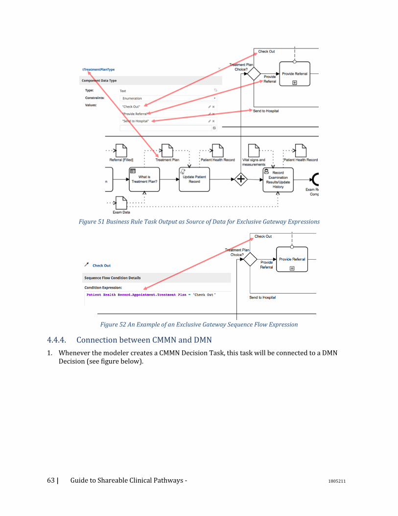
63 | Guide to Shareable Clinical Pathways - 1805211
Figure 51 Business Rule Task Output as Source of Data for Exclusive Gateway Expressions
Figure 52 An Example of an Exclusive Gateway Sequence Flow Expression
4.4.4. Connection between CMMN and DMN
1. Whenever the modeler creates a CMMN Decision Task, this task will be connected to a DMN Decision (see figure below).
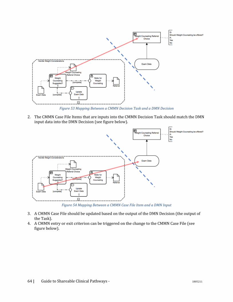
64 | Guide to Shareable Clinical Pathways - 1805211
Figure 53 Mapping Between a CMMN Decision Task and a DMN Decision
2. The CMMN Case File Items that are inputs into the CMMN Decision Task should match the DMN input data into the DMN Decision (see figure below).
Figure 54 Mapping Between a CMMN Case File Item and a DMN Input
3. A CMMN Case File should be updated based on the output of the DMN Decision (the output of the Task).
4. A CMMN entry or exit criterion can be triggered on the change to the CMMN Case File (see figure below).
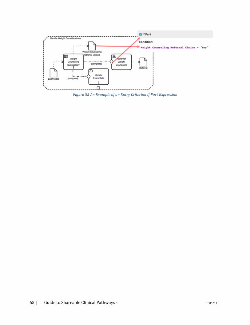
65 | Guide to Shareable Clinical Pathways - 1805211
Figure 55 An Example of an Entry Criterion If Part Expression
66 | Guide to Shareable Clinical Pathways - 1805211
5. Consuming Models 5.1. Introduction One of the benefits of modeling clinical pathways using standard languages semantics is the ability
to share them across organizations. This section describes the process of the receiving organization
would use Shared Clinical Pathways; for discovery, to assessment, to an actual implementation.
5.2. Discovery Phase The first step in sharing clinical pathways is discovering what pathways are available and
determining which of them might be beneficial. This requires that the Shared Clinical Pathway
include a robust set of metadata describing its subject, description, applicability, and provenance.
An organization may decide that they will not move on to the assessment phase for a variety of
reasons, such as competing priorities or resource constraints. Even so, a well-documented clinical
pathway may help readers acquire some knowledge that can help them or their organization
deliver better healthcare.
5.3. Assessment Phase The assessment phase includes the activities associated with evaluating the clinical pathway for
fitness for use within a particular environment at the receiving organization. It should be
approached by a team with a solid understanding of the organization’s needs, resources, and
existing workflows. Experts in the particular clinical or business problem being addressed should
be included in this team.
5.3.1. Applicability The applicability step determines whether some or all of the clinical pathway can be used within
the receiving organization. Applicability is a factor of both the clinical pathway itself and
characteristics of the receiving organization. Applicability criteria for the care pathway include
information about the context of use such as patient characteristics, provider characteristics, and
care settings. Organizational factors to be considered include the existing clinical and technical
skills, existing IT assets, internal and external policies and regulations that might affect the clinical
pathway, and a business plan and analysis that factors in the costs of implementation as well as the
benefits.
As described above, there are many factors that need to be considered. Although this Field Guide is
focused on clinical pathways and process, how information is produced and consumed during these
clinical pathways is a critical and nuanced part of this evaluation. Please see Appendix A – The
Information Ecology of Clinical Care for more discussion about this area.
5.3.2. Simulation Larger organizations may have the resources and the skills to perform simulations comparing their
current state to one or more future states based on utilization of the clinical pathway. A number of
the existing BPM toolsets provide functions that can assist in simulation. Simulations may be
particularly valuable in determining the effects that adopting a particular process will have on
organizational resources.
5.3.3. Acceptance Once a clinical pathway has been deemed applicable and relevant cost and benefit relationships
have been reviewed, the receiving organization choose to incorporate a BPM into their business
67 | Guide to Shareable Clinical Pathways - 1805211
practices. Access to these models is anticipated to include for-profit, nonprofit, and free/open
source approaches. Business transactions appropriate to the acquisition of the needed model are
outside the purview of this guide. Business model.
5.3.4. Localization Phase Once a model is acquired, it will need to be localized to the institution implementing it. Localization
is the process by which the clinical pathway is adapted to the receiving organization’s environment.
Localization included two components: mapping the concepts used in the pathway to local
terminologies, and modeling the local workflow processes.
Workflows: If the clinical pathway has been built according to the recommendations in this guide, it
will differentiate between the clinical essence of the pathway, and the local processes which can
vary without changing the clinical intent. For example, the indications for ordering a blood
transfusion are core to the clinical meaning of the pathway, while the process for ordering and
obtaining the blood would be local to the receiving organization. The receiving organization must
refine the shared clinical pathway by building out these local processes.
5.4. Information, Semantics and Terminologies Aligning the flow of information to support the clinical pathway is necessary to achieve the desired
efficiency and outcomes. As part of this process, the expression of the clinical pathways in standard
process modeling languages using healthcare standard semantics and terminologies facilitates the
process of localization by enabling the receiving organization to effectively map the concepts used
in the clinical pathways to local patient data. Concepts to be mapped include roles, resources,
observations, interventions, diagnoses, etc. Basically, all of the “nouns”
5.5. Implementation Phase The implementation of a BPM is typically the most demanding and expensive part of incorporating
a business process. Choices will be made between automation and manual implementation. In many
cases, a mixed model may be tried.
5.5.1. Automated versus Manual Utilization Depending on the existing capabilities available in the healthcare organization, the Shared Clinical
Pathways can be automated, may be implemented manually, or the institution can implement a
hybrid approach. In addition, for automated implementations there can be multiple standards that
can be utilized. The following table identifies standards that might be used. For each standard, SCPs
will strive to provide documentation, open source tooling and content, and code libraries to
simplify and reduce the implementation time and effort.
Table 3 :approaches to the implementation of Shared Clinical Pathways: automated versus manual implementation.
Implementing Clinical Pathway Functionality
Automated Implementation Manual Implementation
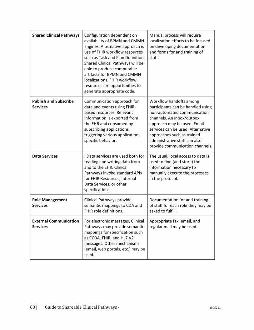
68 | Guide to Shareable Clinical Pathways - 1805211
Shared Clinical Pathways Configuration dependent on availability of BPMN and CMMN Engines. Alternative approach is use of FHIR workflow resources such as Task and Plan Definition. Shared Clinical Pathways will be able to produce computable artifacts for BPMN and CMMN localizations. FHIR workflow resources are opportunities to generate appropriate code.
Manual process will require localization efforts to be focused on developing documentation and forms for and training of staff.
Publish and Subscribe Services
Communication approach for data and events using FHIR-based resources. Relevant information is exported from the EHR and consumed by subscribing applications triggering various application-specific behavior.
Workflow handoffs among participants can be handled using non-automated communication channels. An inbox/outbox approach may be used. Email services can be used. Alternative approaches such as trained administrative staff can also provide communication channels.
Data Services . Data services are used both for reading and writing data from and to the EHR. Clinical Pathways invoke standard APIs for FHIR Resources, internal Data Services, or other specifications.
The usual, local access to data is used to find (and store) the information necessary to manually execute the processes in the protocol.
Role Management Services
Clinical Pathways provide semantic mappings to CDA and FHIR role definitions.
Documentation for and training of staff for each role they may be asked to fulfill.
External Communication Services
For electronic messages, Clinical Pathways may provide semantic mappings for specification such as CCDA, FHIR, and HL7 V2 messages. Other mechanisms (email, web portals, etc.) may be used.
Appropriate fax, email, and regular mail may be used.
69 | Guide to Shareable Clinical Pathways - 1805211
Clinical Decision Support Logic / Services
Multiple options available with OMG DMN, FHIR with FHIR Hooks and CQL, the Arden syntax, and others. And standards-based implementations with languages such as Drools and hybrid implementations our also possible.
For manual localizations, it may not be possible to implement some Clinical Pathway Decision Support Services. Simple ones can be implemented with appropriate documentation where tasks involve computations that can be done by humans without computer assistance
High Level Services (e.g. Order Services)
These services can be characterized as more complex than data services. The services should provide all of the functionality needed, such as allow external applications to ordering a complex series of items. Extensions such as testing for drug-drug interactions and allergies or for bleeding risk should be easily incorporated.
These high-level complex services will need to be decomposed to be able to be supported by manual processes.
5.5.2. Standards-Based Technologies Local Utilization is the methods and procedure which can be used to operationalize the Shared
Clinical Pathways within an organization.
The following table describes some sample localizations of SCP features for use within an
organization.
Clinical Pathway Functionality Possible Implementation Approach
Business Process Management
(BPMN, CMMN, DMN)
JBPMN, FHIR Plan Definition, CDS Hooks
Publish and Subscribe Services FHIR Pub Sub
Data Services FHIR Profiles
Role Management Services JBPMN, FHIR Participant Resource

70 | Guide to Shareable Clinical Pathways - 1805211
Communication Services FHIR Pub Sub,
Clinical Decision Support Logic /
Services
CQL, OMG Decision Logic
High Level Services (e.g. Order
Services)
J2EE, HSSP Order Management Services
Terminology Services SOLAR
The examples below are specific to the problems of 1) converting a CMMN model to a BPMN model, 2) managing semantics using taxonomies, 3) alternate ways of expressing decision logic, 4) a terminology mapping example. They might fit better in an appendix or perhaps in the patterns chapter Business Process Management Example If a Consumer of a Shared Clinical Pathway does not have an engine that supports CMMN, then it is
possible to convert the CMMN Case Models of the Clinical Pathway into BPMN Sub-Processes.
There are some behavioral overlaps between CMMN and BPMN, so those overlaps can be mapped
easily. For example, a performance dependency in CMMN is modeled like this (see figure below):
Figure 56 : A Performance Dependency in CMMN
The same performance dependency in BPMN is shown through a simple Sequence Flow (see figure
below):
Figure 57 : A Performance Dependency in BPMN
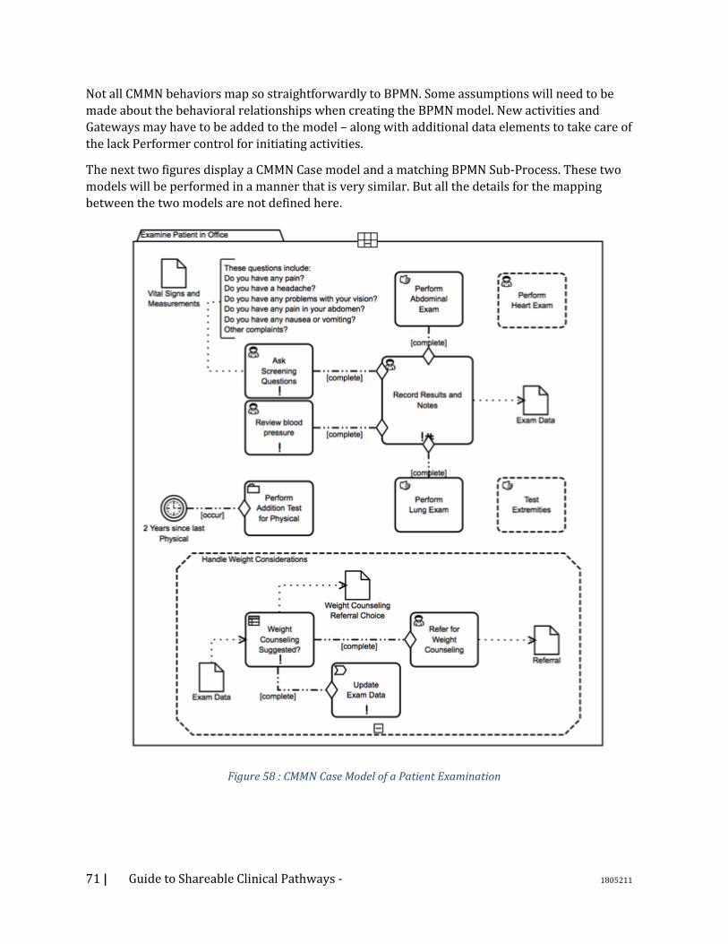
71 | Guide to Shareable Clinical Pathways - 1805211
Not all CMMN behaviors map so straightforwardly to BPMN. Some assumptions will need to be
made about the behavioral relationships when creating the BPMN model. New activities and
Gateways may have to be added to the model – along with additional data elements to take care of
the lack Performer control for initiating activities.
The next two figures display a CMMN Case model and a matching BPMN Sub-Process. These two
models will be performed in a manner that is very similar. But all the details for the mapping
between the two models are not defined here.
Figure 58 : CMMN Case Model of a Patient Examination
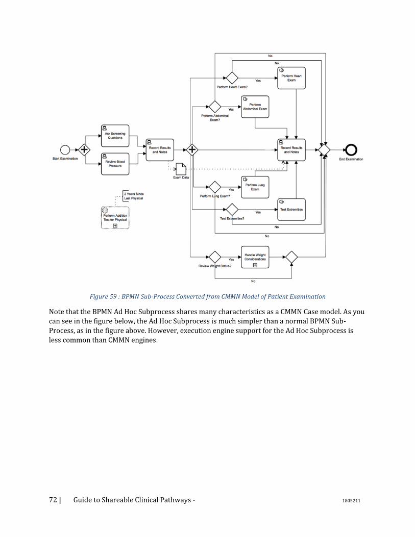
72 | Guide to Shareable Clinical Pathways - 1805211
Figure 59 : BPMN Sub-Process Converted from CMMN Model of Patient Examination
Note that the BPMN Ad Hoc Subprocess shares many characteristics as a CMMN Case model. As you
can see in the figure below, the Ad Hoc Subprocess is much simpler than a normal BPMN Sub-
Process, as in the figure above. However, execution engine support for the Ad Hoc Subprocess is
less common than CMMN engines.
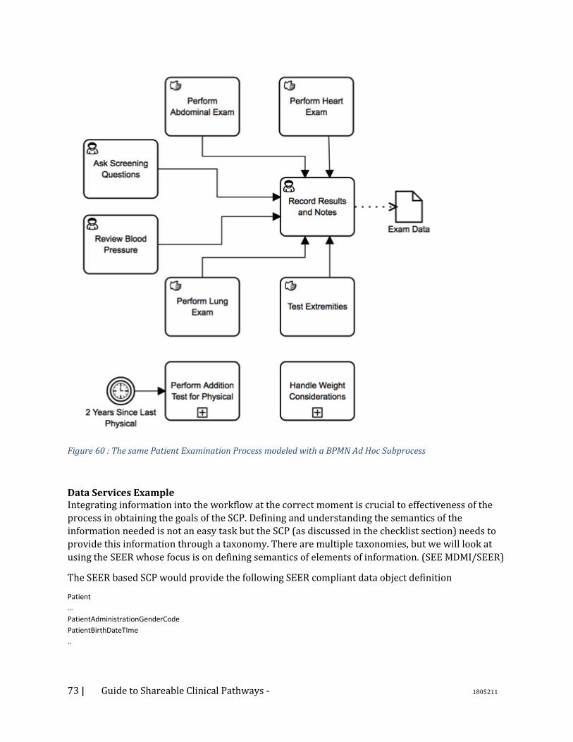
73 | Guide to Shareable Clinical Pathways - 1805211
Figure 60 : The same Patient Examination Process modeled with a BPMN Ad Hoc Subprocess
Data Services Example Integrating information into the workflow at the correct moment is crucial to effectiveness of the
process in obtaining the goals of the SCP. Defining and understanding the semantics of the
information needed is not an easy task but the SCP (as discussed in the checklist section) needs to
provide this information through a taxonomy. There are multiple taxonomies, but we will look at
using the SEER whose focus is on defining semantics of elements of information. (SEE MDMI/SEER)
The SEER based SCP would provide the following SEER compliant data object definition
Patient
…
PatientAdministrationGenderCode
PatientBirthDateTIme
..

74 | Guide to Shareable Clinical Pathways - 1805211
The SEER itself provides important link to existing standards allowing discovery of a standard
based information definition such as US Core Patient FHIR (see profile) which could be utilized as
an inline replacement of the BPMN data object and services. Additionally, the SEER is part of the
MDMI specification which publishes executable transformation mappings of such specifications.
In our hello work example, the Get Patient Step would be replaced with a FHIR Rest API request for
the US Core Patient resource and leverage the MDMI mapping to produce the appropriate BPMN
data object instance for the SCP to operate.
Clinical Decision Support Logic / Services Example Decision points are a basic component of workflow definitions and as such an SCP will define both
trivial and complex decisions. The SCP will define a DMN for each of these decisions but in a
particular mode decision for IsPregnant, the need to use a local version IsPregnant could be
completed through the use of Clinical Quality Language (CQL). See(https://ecqi.healthit.gov/cql)
The DMN would provide the inputs and the expected outputs from the decision but the actual
execution of the decision would be within a CQL server.
The DMN for IsPregnant would be
while the similar approach for CQL is
define "Pregnancy Conditions":
[Condition: "Pregnancy"] C
where C.clinicalStatus = 'active'
and C.verificationStatus = 'confirmed'
define "Is Patient Pregnant":
Patient.gender = 'female'
and exists ("Pregnancy Conditions")

75 | Guide to Shareable Clinical Pathways - 1805211
Terminology Services Example A large portion of semantics and interoperability is the effective and accurate use of terminologies
and while mapping between such terminologies is not optimal there are times where your only
choice is to map between one vocabulary to another.
Take for instance in our hello world example, the data element Immunization Administered Medication Code as part of the SEER based SCP declares that the code should be SNOMED CT while the local data services used RxNorm which then requires a transformation between them. The management and definition of these mapping is beyond the scope of this document but the use of terminology service such as FHIR (SEE FHIR Term) is an appropriate example of localizing the SCP to provide the SCP the correct value to accurately and effectively execute the workflow.
76 | Guide to Shareable Clinical Pathways - 1805211
6. Appendix A – The Information Ecology of Clinical Care
Information is a critical resource for the practice of clinical health care. When the flow of information matches appropriate workflow of care, significant gains in quality and efficiency can be achieved. But when information flow contradicts, it can rearrange clinical workflow by accident rather than by design. Information constrains care activity in ways that are analogous to physical resources: Missing information causes delays to begin activities; Performing an activity without complete and accurate information increases the risk of medical errors; And, better information can reduce the time and effort needed for doctor and staff to perform care. In order to reflect the constraints of information accurately in models of care we need to clarify some distinctions that are important to health information technology. • The term “health information technology system” is something of a misnomer because its
contents are actually produced by a combination of the manual and cognitive activities of clinical personnel as well as the functions of computers. Consequently, the information needed for care resides or gets changed in a variety of media. Important clinical information resources include equipment, paper notes, paper records, electronic medical record systems, and white boards. These will remain important in clinics and hospitals for the foreseeable future. Their contents often overlap and can be highly dynamic, leading to serious problems of accuracy, synchronization, and burdensome manual integration. They must be captured for model completeness, but also need to be captured so they can be addressed in system redesigns.
• The variety of information resources includes people and even inanimate objects. Clinical colleagues and patients, themselves, have long been key information resources. Patients have dual roles as information resources during exams versus their obvious role as the object of care activity. Inanimate objects in the observable environment represent information that impacts planning and decision making (e.g., “Exam room #6 is vacant now,” or, “The ER waiting room is SRO.”) The dual role of clinicians as performers of activity versus information resources must be reflected in an accurate model. Removing the burdens for clinicians to transform and remember large amounts of complex information is an important purpose of health information technology.
• Information is often more than a single datum. For just one example, many data have to be filtered and processed to in order to detect “ventricular arrhythmia.” The that single term provides information that is actionable to make decisions. The level of granularity to capture requirements for information is typically much less detailed than data requirements to satisfy them. The level of granularity for BPM models that exposes the “what and where” of information use can be a good heuristic to decide how much activity detail to show.
• It reduces confusion to distinguish two roles that information plays. The roles are determined
by activity context. For example, a diagnosis can be the abstract object of cognitive clinical work when a doctor is developing it. That diagnosis can then be an information resource for subsequent activity, such as when it is needed to develop a treatment plan of orders. The orders, in turn, become key information resources to carry out physical care activity on the patient. Notes on carrying out orders and patients’ response are developed during care, then become an information resource for revising the treatment plan, and so on. It’s often clearer to
77 | Guide to Shareable Clinical Pathways - 1805211
model the creation of an information resource with its own sub-process- one that is scoped to begin with the triggering event and ends when the information resource reaches its goal state. Subsequent revision of that information resource may reuse the sub-process or it may occur as a by-product of other, later tasks.
• The flow of information about patient care is not the same as the workflow of care for the patient. They often take parallel flows. There are many examples where the flows diverge when images, tests or consults are done on the patient and analyzed as abstract work objects within their own sub-workflows while the workflow of the current care plan continues on the patient. The workflow for analyzing the tests, etc. should be modeled as coordinated support systems. The flows converge when the results are used as information resources.
• Patient care requires physical resources that are often in high demand, such as scarce equipment or skilled personnel. Information about their capability and availability are key parts of a critical information flow that is needed to plan, schedule and coordinate patient care.
These aspects of the information eco-system of a clinical environment are fundamentally important for any model to represent the way clinical care is performed. Since information constrains activity, workflow models need to reflect the constraints of the information needed by tasks, the information resource that provides it to tasks, and where it goes if values are changed or aggregated. Information flow that is indexed to tasks can clarify precision information requirements for coordination, precision interoperability, and opportunities to apply information technology that might otherwise go overlooked.
In summary, there are five reasons for reflecting the usage and change of information in models of clinical care:
1) Clinical health care depends on information that is accessed or changed by a wide variety of resources, not only by computers.
2) Valid data requirements should be derived from and prioritized by clinical need for information.
3) Information is often developed as an abstract object of cognitive clinical work, and then serves as a key resource for subsequent care activity.
4) The strong interdependency of information and activity makes reviewing activity models a good technique to elicit information requirements, and vice versa;
5) Better information resources should reduce the amount of physical resources needed for care, especially the energy and scarce time of busy clinicians.
78 | Guide to Shareable Clinical Pathways - 1805211
7. Appendix B – Design Patterns 7.1. DMN: Simple Scoring Algorithm 7.1.1. Description The simple scoring algorithm is a specialization of a quantitative decision. It takes multiple inputs, and assigns an integer value to each, and sums the results to arrive at a score.
7.1.2. Problem In medicine there are a large number of simple algorithms used to assess risk, assign probability to various conditions, and predict outcomes. One common form of these algorithms is based on ‘scorecard9’ predictive models. The models are formulated in terms of a (usually brief) list of relevant clinical findings. Each of these findings is associated with a value (typically a small integer) and the scoring algorithm works through the simple expedient of adding together the values of all of the positive findings and testing the result against a threshold. Because of their pure computational nature, such algorithms can be modelled as DMN decisions. For example, The Revised Geneva Score is a score used in the diagnostic workup of possible pulmonary embolism (PE). A group of eight findings frequently associated with PE are each assigned an integer weight (see Figure 61 Patient with Suspected PE ). The clinician sums the weights of the positive findings and uses the resulting score for further decision making. If the score is greater than or equal to 11, an imaging exam is indicated. If less, a blood test (the D-dimer) is used to further assess the probability of PE. Figure 61 Patient with Suspected PE shows an algorithm for the workup of suspected pulmonary embolism. The initial testing decision is based on a score produced by adding the values associated with the findings that are positive. Totals under 10 lead to a blood test (the D-dimer); totals of 11 or greater suggest the need for a definitive radiology exam (the computed tomography-pulmonary angiogram (CTPA)). The graphic goes on to describe further diagnostic decision making after the initial testing decision has been made.
9 See also http://dmg.org/pmml/v4-3/Scorecard.html
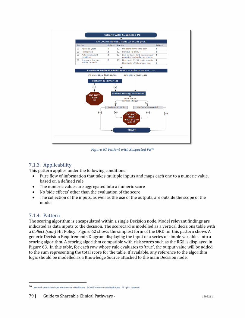
79 | Guide to Shareable Clinical Pathways - 1805211
Figure 61 Patient with Suspected PE10
7.1.3. Applicability This pattern applies under the following conditions: • Pure flow of information that takes multiple inputs and maps each one to a numeric value,
based on a defined rule • The numeric values are aggregated into a numeric score • No ‘side effects’ other than the evaluation of the score • The collection of the inputs, as well as the use of the outputs, are outside the scope of the
model
7.1.4. Pattern The scoring algorithm is encapsulated within a single Decision node. Model relevant findings are indicated as data inputs to the decision. The scorecard is modelled as a vertical decisions table with a Collect (sum) Hit Policy. Figure 62 shows the simplest form of the DRD for this pattern shows A generic Decision Requirements Diagram displaying the input of a series of simple variables into a scoring algorithm. A scoring algorithm compatible with risk scores such as the RGS is displayed in Figure 63. In this table, for each row whose rule evaluates to ‘true’, the output value will be added to the sum representing the total score for the table. If available, any reference to the algorithm logic should be modelled as a Knowledge Source attached to the main Decision node.
10 Used with permission from Intermountain Healthcare. © 2012 Intermountain Healthcare. All rights reserved.
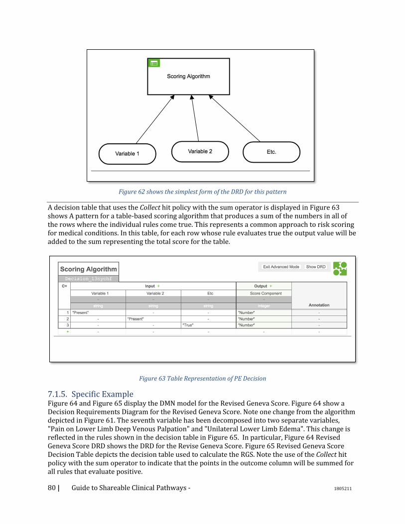
80 | Guide to Shareable Clinical Pathways - 1805211
Figure 62 shows the simplest form of the DRD for this pattern
A decision table that uses the Collect hit policy with the sum operator is displayed in Figure 63 shows A pattern for a table-based scoring algorithm that produces a sum of the numbers in all of the rows where the individual rules come true. This represents a common approach to risk scoring for medical conditions. In this table, for each row whose rule evaluates true the output value will be added to the sum representing the total score for the table.
Figure 63 Table Representation of PE Decision
7.1.5. Specific Example Figure 64 and Figure 65 display the DMN model for the Revised Geneva Score. Figure 64 show a Decision Requirements Diagram for the Revised Geneva Score. Note one change from the algorithm depicted in Figure 61. The seventh variable has been decomposed into two separate variables, "Pain on Lower Limb Deep Venous Palpation" and "Unilateral Lower Limb Edema". This change is reflected in the rules shown in the decision table in Figure 65. In particular, Figure 64 Revised Geneva Score DRD shows the DRD for the Revise Geneva Score. Figure 65 Revised Geneva Score Decision Table depicts the decision table used to calculate the RGS. Note the use of the Collect hit policy with the sum operator to indicate that the points in the outcome column will be summed for all rules that evaluate positive.
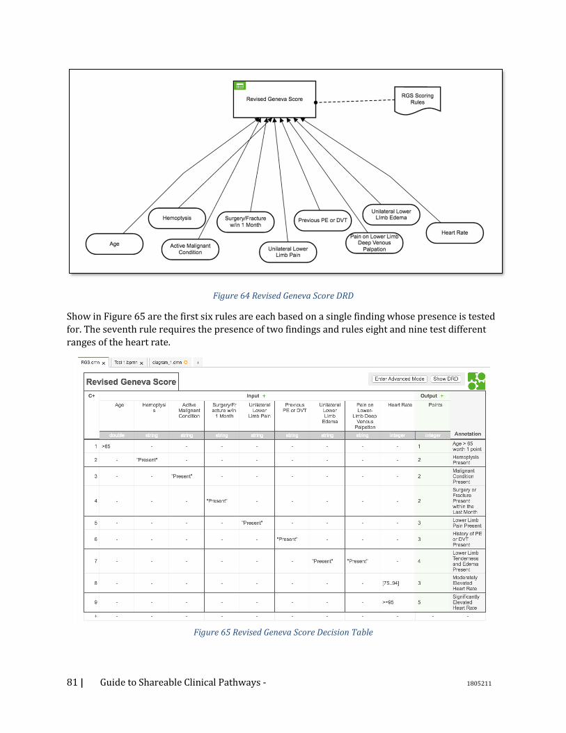
81 | Guide to Shareable Clinical Pathways - 1805211
Figure 64 Revised Geneva Score DRD
Show in Figure 65 are the first six rules are each based on a single finding whose presence is tested
for. The seventh rule requires the presence of two findings and rules eight and nine test different
ranges of the heart rate.
Figure 65 Revised Geneva Score Decision Table
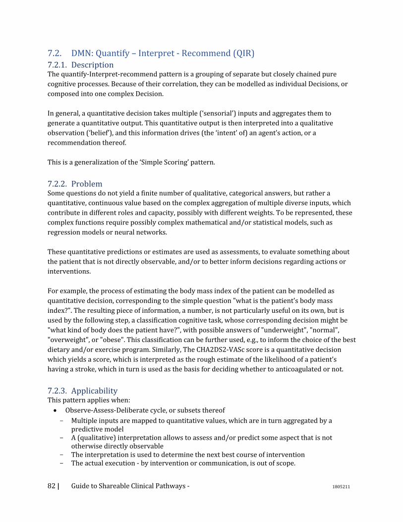
82 | Guide to Shareable Clinical Pathways - 1805211
7.2. DMN: Quantify – Interpret - Recommend (QIR) 7.2.1. Description The quantify-Interpret-recommend pattern is a grouping of separate but closely chained pure
cognitive processes. Because of their correlation, they can be modelled as individual Decisions, or
composed into one complex Decision.
In general, a quantitative decision takes multiple (‘sensorial’) inputs and aggregates them to
generate a quantitative output. This quantitative output is then interpreted into a qualitative
observation (‘belief’), and this information drives (the ‘intent’ of) an agent’s action, or a
recommendation thereof.
This is a generalization of the ‘Simple Scoring’ pattern.
7.2.2. Problem Some questions do not yield a finite number of qualitative, categorical answers, but rather a
quantitative, continuous value based on the complex aggregation of multiple diverse inputs, which
contribute in different roles and capacity, possibly with different weights. To be represented, these
complex functions require possibly complex mathematical and/or statistical models, such as
regression models or neural networks.
These quantitative predictions or estimates are used as assessments, to evaluate something about
the patient that is not directly observable, and/or to better inform decisions regarding actions or
interventions.
For example, the process of estimating the body mass index of the patient can be modelled as
quantitative decision, corresponding to the simple question "what is the patient's body mass
index?". The resulting piece of information, a number, is not particularly useful on its own, but is
used by the following step, a classification cognitive task, whose corresponding decision might be
"what kind of body does the patient have?", with possible answers of "underweight", "normal",
"overweight", or "obese". This classification can be further used, e.g., to inform the choice of the best
dietary and/or exercise program. Similarly, The CHA2DS2-VASc score is a quantitative decision
which yields a score, which is interpreted as the rough estimate of the likelihood of a patient’s
having a stroke, which in turn is used as the basis for deciding whether to anticoagulated or not.
7.2.3. Applicability This pattern applies when:
• Observe-Assess-Deliberate cycle, or subsets thereof
Multiple inputs are mapped to quantitative values, which are in turn aggregated by a predictive model
A (qualitative) interpretation allows to assess and/or predict some aspect that is not otherwise directly observable
The interpretation is used to determine the next best course of intervention The actual execution - by intervention or communication, is out of scope.
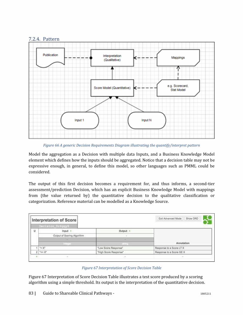
83 | Guide to Shareable Clinical Pathways - 1805211
7.2.4. Pattern
Figure 66 A generic Decision Requirements Diagram illustrating the quantify/interpret pattern
Model the aggregation as a Decision with multiple data Inputs, and a Business Knowledge Model
element which defines how the inputs should be aggregated. Notice that a decision table may not be
expressive enough, in general, to define this model, so other languages such as PMML could be
considered.
The output of this first decision becomes a requirement for, and thus informs, a second-tier
assessment/prediction Decision, which has an explicit Business Knowledge Model with mappings
from (the value returned by) the quantitative decision to the qualitative classification or
categorization. Reference material can be modelled as a Knowledge Source.
Figure 67 Interpretation of Score Decision Table
Figure 67 Interpretation of Score Decision Table illustrates a test score produced by a scoring
algorithm using a simple threshold. Its output is the interpretation of the quantitative decision.
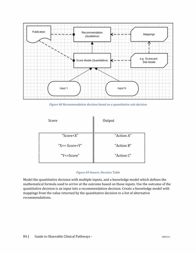
84 | Guide to Shareable Clinical Pathways - 1805211
Figure 68 Recommendation decision based on a quantitative sub-decision
Score Output
1 "Score<X" "Action A"
2 "X<= Score<Y" "Action B"
3 "Y<=Score" "Action C"
Figure 69 Generic Decision Table
Model the quantitative decision with multiple inputs, and a knowledge model which defines the
mathematical formula used to arrive at the outcome based on those inputs. Use the outcome of the
quantitative decision is an input into a recommendation decision. Create a knowledge model with
mappings from the value returned by the quantitative decision to a list of alternative
recommendations.
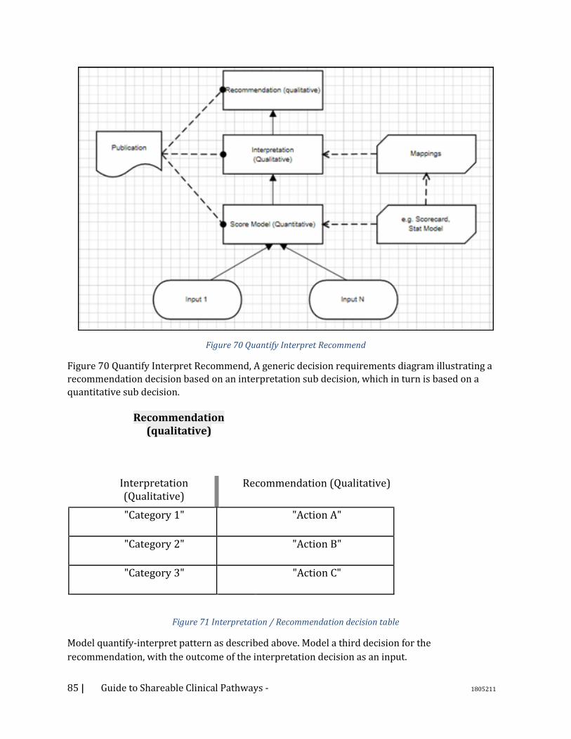
85 | Guide to Shareable Clinical Pathways - 1805211
Figure 70 Quantify Interpret Recommend
Figure 70 Quantify Interpret Recommend, A generic decision requirements diagram illustrating a
recommendation decision based on an interpretation sub decision, which in turn is based on a
quantitative sub decision.
Recommendation (qualitative)
Interpretation (Qualitative)
Recommendation (Qualitative)
"Category 1" "Action A"
"Category 2" "Action B"
"Category 3" "Action C"
Figure 71 Interpretation / Recommendation decision table
Model quantify-interpret pattern as described above. Model a third decision for the
recommendation, with the outcome of the interpretation decision as an input.
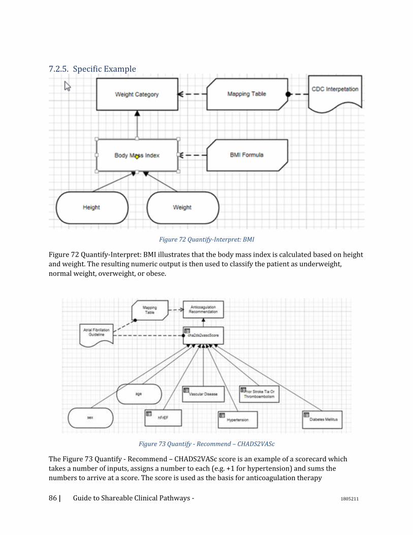
86 | Guide to Shareable Clinical Pathways - 1805211
7.2.5. Specific Example
Figure 72 Quantify-Interpret: BMI
Figure 72 Quantify-Interpret: BMI illustrates that the body mass index is calculated based on height
and weight. The resulting numeric output is then used to classify the patient as underweight,
normal weight, overweight, or obese.
Figure 73 Quantify - Recommend – CHADS2VASc
The Figure 73 Quantify - Recommend – CHADS2VASc score is an example of a scorecard which
takes a number of inputs, assigns a number to each (e.g. +1 for hypertension) and sums the
numbers to arrive at a score. The score is used as the basis for anticoagulation therapy
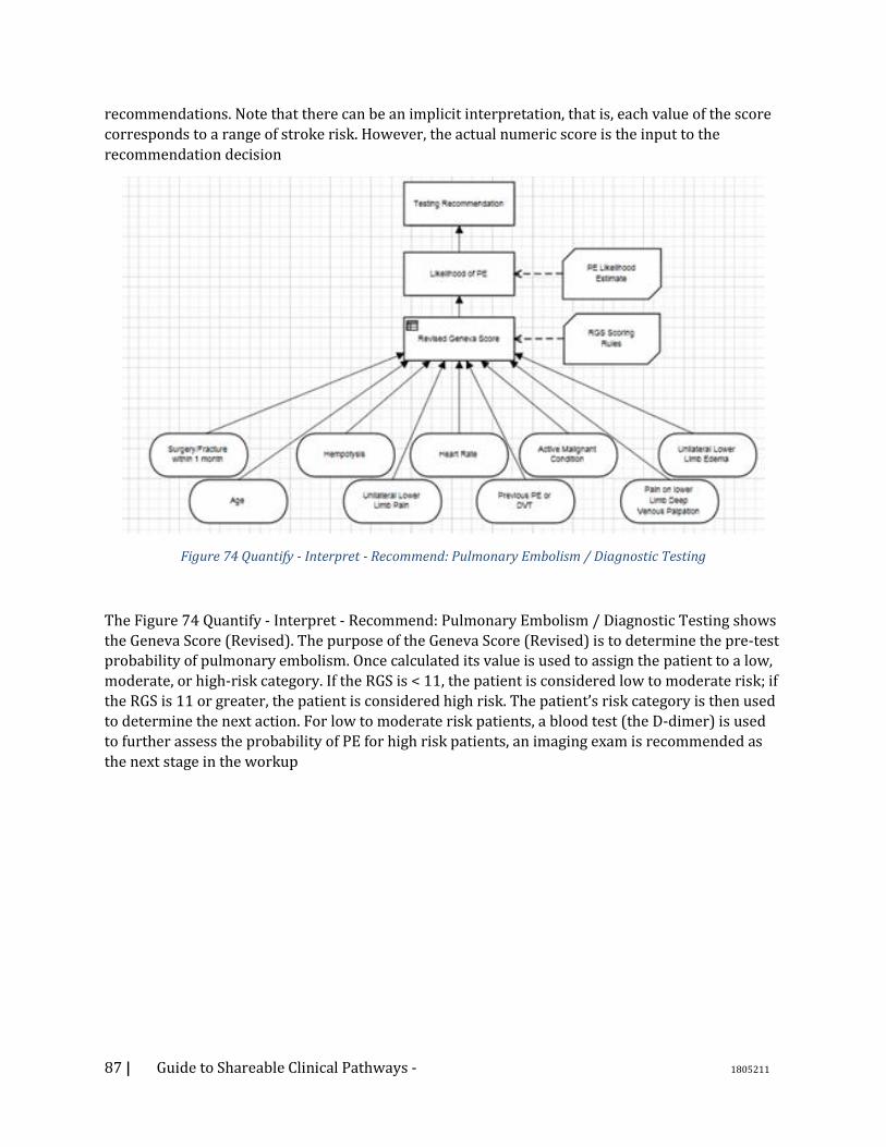
87 | Guide to Shareable Clinical Pathways - 1805211
recommendations. Note that there can be an implicit interpretation, that is, each value of the score
corresponds to a range of stroke risk. However, the actual numeric score is the input to the
recommendation decision
Figure 74 Quantify - Interpret - Recommend: Pulmonary Embolism / Diagnostic Testing
The Figure 74 Quantify - Interpret - Recommend: Pulmonary Embolism / Diagnostic Testing shows
the Geneva Score (Revised). The purpose of the Geneva Score (Revised) is to determine the pre-test
probability of pulmonary embolism. Once calculated its value is used to assign the patient to a low,
moderate, or high-risk category. If the RGS is < 11, the patient is considered low to moderate risk; if
the RGS is 11 or greater, the patient is considered high risk. The patient’s risk category is then used
to determine the next action. For low to moderate risk patients, a blood test (the D-dimer) is used
to further assess the probability of PE for high risk patients, an imaging exam is recommended as
the next stage in the workup
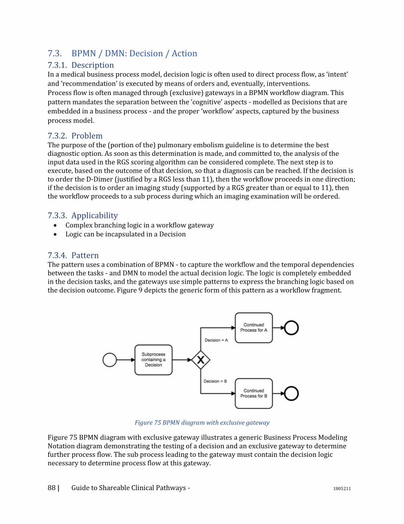
88 | Guide to Shareable Clinical Pathways - 1805211
7.3. BPMN / DMN: Decision / Action 7.3.1. Description In a medical business process model, decision logic is often used to direct process flow, as ‘intent’
and ‘recommendation’ is executed by means of orders and, eventually, interventions.
Process flow is often managed through (exclusive) gateways in a BPMN workflow diagram. This
pattern mandates the separation between the ‘cognitive’ aspects - modelled as Decisions that are
embedded in a business process - and the proper ‘workflow’ aspects, captured by the business
process model.
7.3.2. Problem The purpose of the (portion of the) pulmonary embolism guideline is to determine the best diagnostic option. As soon as this determination is made, and committed to, the analysis of the input data used in the RGS scoring algorithm can be considered complete. The next step is to execute, based on the outcome of that decision, so that a diagnosis can be reached. If the decision is to order the D-Dimer (justified by a RGS less than 11), then the workflow proceeds in one direction; if the decision is to order an imaging study (supported by a RGS greater than or equal to 11), then the workflow proceeds to a sub process during which an imaging examination will be ordered.
7.3.3. Applicability • Complex branching logic in a workflow gateway • Logic can be incapsulated in a Decision
7.3.4. Pattern The pattern uses a combination of BPMN - to capture the workflow and the temporal dependencies between the tasks - and DMN to model the actual decision logic. The logic is completely embedded in the decision tasks, and the gateways use simple patterns to express the branching logic based on the decision outcome. Figure 9 depicts the generic form of this pattern as a workflow fragment.
Figure 75 BPMN diagram with exclusive gateway
Figure 75 BPMN diagram with exclusive gateway illustrates a generic Business Process Modeling Notation diagram demonstrating the testing of a decision and an exclusive gateway to determine further process flow. The sub process leading to the gateway must contain the decision logic necessary to determine process flow at this gateway.
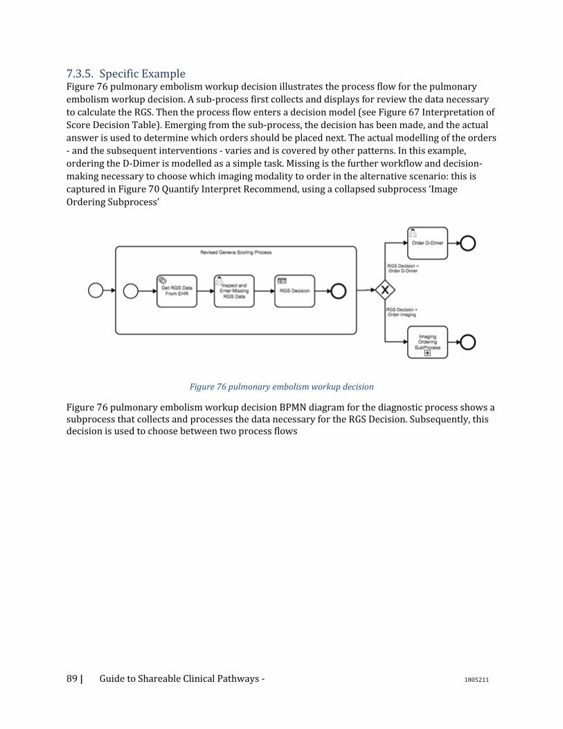
89 | Guide to Shareable Clinical Pathways - 1805211
7.3.5. Specific Example Figure 76 pulmonary embolism workup decision illustrates the process flow for the pulmonary
embolism workup decision. A sub-process first collects and displays for review the data necessary
to calculate the RGS. Then the process flow enters a decision model (see Figure 67 Interpretation of
Score Decision Table). Emerging from the sub-process, the decision has been made, and the actual
answer is used to determine which orders should be placed next. The actual modelling of the orders
- and the subsequent interventions - varies and is covered by other patterns. In this example,
ordering the D-Dimer is modelled as a simple task. Missing is the further workflow and decision-
making necessary to choose which imaging modality to order in the alternative scenario: this is
captured in Figure 70 Quantify Interpret Recommend, using a collapsed subprocess ‘Image
Ordering Subprocess’
Figure 76 pulmonary embolism workup decision
Figure 76 pulmonary embolism workup decision BPMN diagram for the diagnostic process shows a subprocess that collects and processes the data necessary for the RGS Decision. Subsequently, this decision is used to choose between two process flows
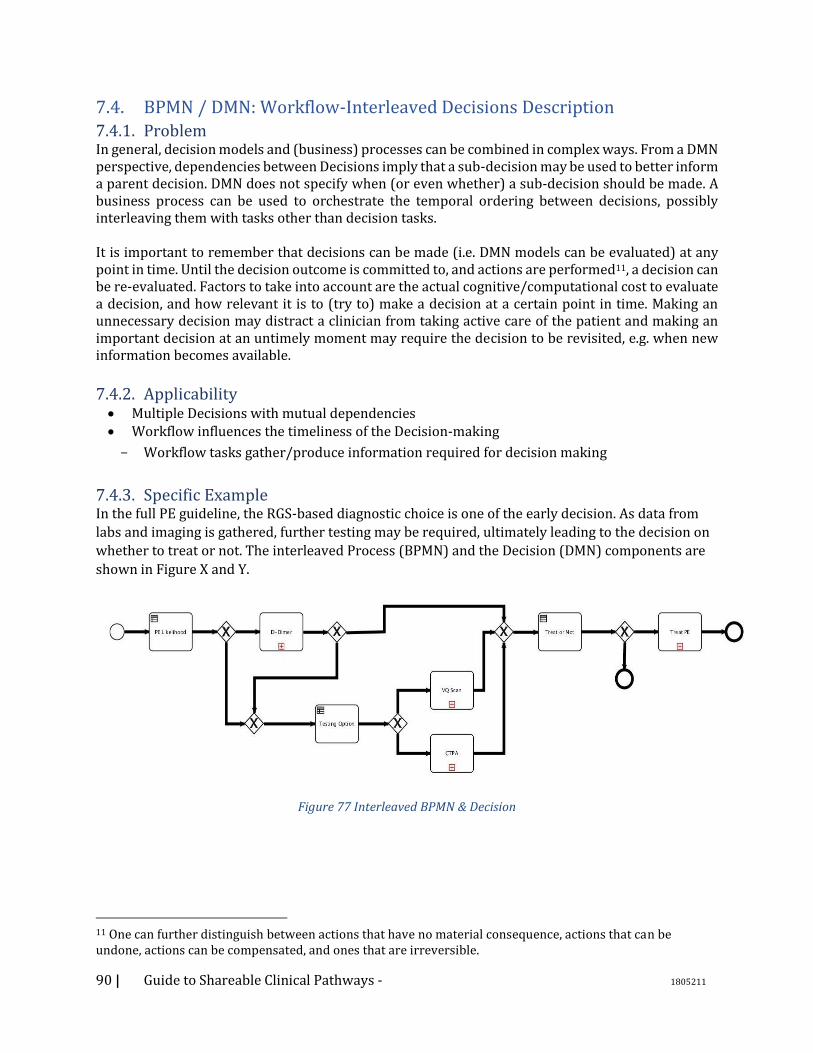
90 | Guide to Shareable Clinical Pathways - 1805211
7.4. BPMN / DMN: Workflow-Interleaved Decisions Description 7.4.1. Problem In general, decision models and (business) processes can be combined in complex ways. From a DMN perspective, dependencies between Decisions imply that a sub-decision may be used to better inform a parent decision. DMN does not specify when (or even whether) a sub-decision should be made. A business process can be used to orchestrate the temporal ordering between decisions, possibly interleaving them with tasks other than decision tasks. It is important to remember that decisions can be made (i.e. DMN models can be evaluated) at any point in time. Until the decision outcome is committed to, and actions are performed11, a decision can be re-evaluated. Factors to take into account are the actual cognitive/computational cost to evaluate a decision, and how relevant it is to (try to) make a decision at a certain point in time. Making an unnecessary decision may distract a clinician from taking active care of the patient and making an important decision at an untimely moment may require the decision to be revisited, e.g. when new information becomes available.
7.4.2. Applicability • Multiple Decisions with mutual dependencies • Workflow influences the timeliness of the Decision-making
Workflow tasks gather/produce information required for decision making
7.4.3. Specific Example In the full PE guideline, the RGS-based diagnostic choice is one of the early decision. As data from
labs and imaging is gathered, further testing may be required, ultimately leading to the decision on
whether to treat or not. The interleaved Process (BPMN) and the Decision (DMN) components are
shown in Figure X and Y.
Figure 77 Interleaved BPMN & Decision
11 One can further distinguish between actions that have no material consequence, actions that can be undone, actions can be compensated, and ones that are irreversible.
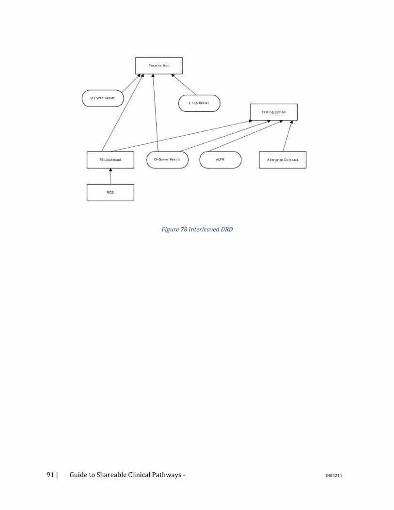
91 | Guide to Shareable Clinical Pathways - 1805211
Figure 78 Interleaved DRD
92 | Guide to Shareable Clinical Pathways - 1805211
7.5. DMN: Team-based decision 7.5.1. Description
A team-based decision is a specialization of a multi-perspective decision. It involves multiple agents
making the same decision, using individual - but possibly overlapping - decision criteria, decision
logic and knowledge sources. Eventually, consensus must be reached and possible conflict must be
resolved before a final determination can be made.
7.5.2. Problem Complex decisions often involve reaching consensus among decision-makers who bring different
perspectives to the same decision. In healthcare, many decisions are made collaboratively.
For example, determining the best treatment approach for a patient may require the input of experts
from multiple disciplines. In cancer care, tumor boards may be convened to determine the best
therapy for a patient. The board could include a radiation oncologist, a medical oncologist, and a
surgeon, as well as other specialists. Each agent takes into account the patient data for the case and
the published evidence, but each brings different experience and tacit knowledge to the decision. The
ultimate decision is made by consensus.
Another example of the team-based decision in healthcare is shared decision-making. Shared decision-making plays an important role in patient engagement. Patients who participate in decision-making are more likely to be compliant with the selected therapy. Patients and clinicians consider treatment options using multiple criteria which are ranked based on patient preference
7.5.3. Applicability This pattern applies under the following conditions:
• There are two or more distinct decision-makers trying to make the same decision in consultation with one another
• All decision-makers have access to a common set of information. In addition, each decision-maker may have access to unique information and use unique decision logic.
• The decision is reached collaboratively. There is only one conclusion.
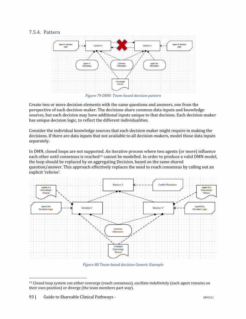
93 | Guide to Shareable Clinical Pathways - 1805211
7.5.4. Pattern
Figure 79 DMN: Team-based decision pattern
Create two or more decision elements with the same questions and answers, one from the perspective of each decision-maker. The decisions share common data inputs and knowledge sources, but each decision may have additional inputs unique to that decision. Each decision-maker has unique decision logic, to reflect the different individualities. Consider the individual knowledge sources that each decision maker might require in making the decisions. If there are data inputs that not available to all decision-makers, model those data inputs separately. In DMN, closed loops are not supported. An iterative process where two agents (or more) influence each other until consensus is reached12 cannot be modelled. In order to produce a valid DMN model, the loop should be replaced by an aggregating Decision, based on the same shared question/answer. This approach effectively replaces the need to reach consensus by calling out an explicit ‘referee’.
Figure 80 Team-based decision Generic Example
12 Closed loop system can either converge (reach consensus), oscillate indefinitely (each agent remains on their own position) or diverge (the team members part way).
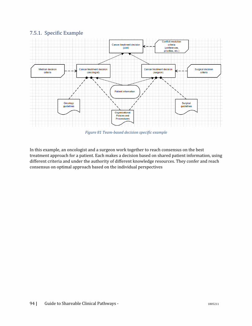
94 | Guide to Shareable Clinical Pathways - 1805211
7.5.1. Specific Example
Figure 81 Team-based decision specific example
In this example, an oncologist and a surgeon work together to reach consensus on the best
treatment approach for a patient. Each makes a decision based on shared patient information, using
different criteria and under the authority of different knowledge resources. They confer and reach
consensus on optimal approach based on the individual perspectives
95 | Guide to Shareable Clinical Pathways - 1805211
7.6. DMN: Computer-aided decision support (CDS) 7.6.1. Description
A CDS pattern is a specialization of the multi-perspective pattern. It is used to model a (clinical)
decision made by a human agent which is informed by a decision made by a computer. The
computer decision aids the human by making the decision and proposing a recommendation.
7.6.2. Problem Distributed cognition is common in knowledge work. Human decisions are often aided by
computerized decision algorithms. The computer decisions may be overridden when the human
agent takes into account inputs which are not available to or used by the computer.
In health care, clinical decision support (CDS) systems present alerts, reminders, and
recommendations to clinicians at the point of care to enforce desired behaviors or prevent errors
and omissions. For example, there are well-accepted guidelines on prescribing anticoagulation for
patients with atrial fibrillation which take into account a patient's likelihood of stroke (CHA2DS2-
VASc) and likelihood of major bleeding (HAS-BLED). CDS systems can calculate these scores and
make a recommendation on whether or not to anticoagulated. The clinician takes that
recommendation into account, along with other inputs, including both data not found in the
patient's record and data contained in the patient's record but not used in the logic of the CDS rule,
to make the actual decision whether or not to prescribe an anticoagulant.
7.6.3. Applicability This pattern applies under the following conditions:
• There are two distinct decision-makers trying to make the same decision: The human and the computer system.
• Both decision-makers base their decisions on the same premises to the degree possible. (data, information, and knowledge)
• The human is the decision-maker who is ultimately responsible and accountable for the decision.
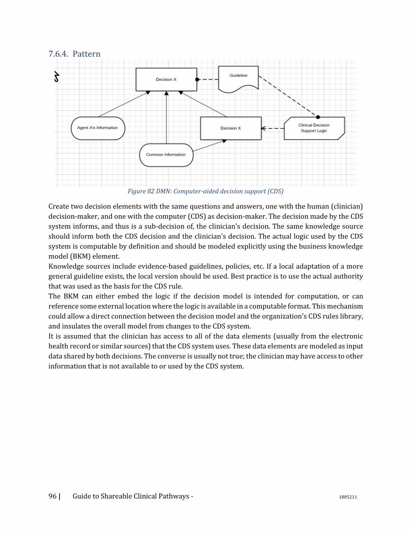
96 | Guide to Shareable Clinical Pathways - 1805211
7.6.4. Pattern
Figure 82 DMN: Computer-aided decision support (CDS)
Create two decision elements with the same questions and answers, one with the human (clinician)
decision-maker, and one with the computer (CDS) as decision-maker. The decision made by the CDS
system informs, and thus is a sub-decision of, the clinician's decision. The same knowledge source
should inform both the CDS decision and the clinician's decision. The actual logic used by the CDS
system is computable by definition and should be modeled explicitly using the business knowledge
model (BKM) element.
Knowledge sources include evidence-based guidelines, policies, etc. If a local adaptation of a more
general guideline exists, the local version should be used. Best practice is to use the actual authority
that was used as the basis for the CDS rule.
The BKM can either embed the logic if the decision model is intended for computation, or can
reference some external location where the logic is available in a computable format. This mechanism
could allow a direct connection between the decision model and the organization's CDS rules library,
and insulates the overall model from changes to the CDS system.
It is assumed that the clinician has access to all of the data elements (usually from the electronic
health record or similar sources) that the CDS system uses. These data elements are modeled as input
data shared by both decisions. The converse is usually not true; the clinician may have access to other
information that is not available to or used by the CDS system.
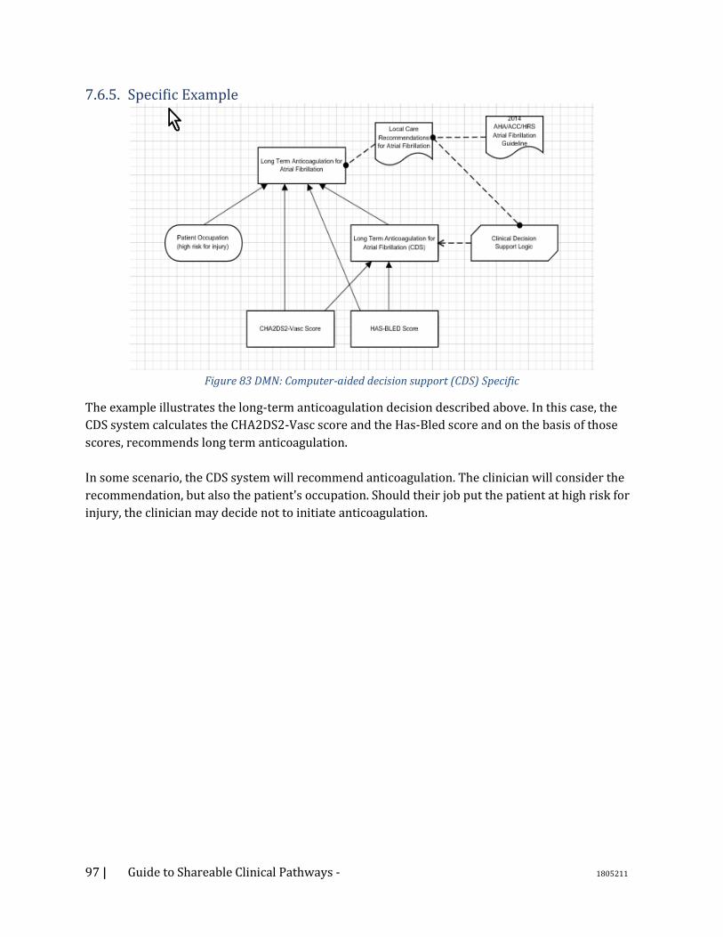
97 | Guide to Shareable Clinical Pathways - 1805211
7.6.5. Specific Example
Figure 83 DMN: Computer-aided decision support (CDS) Specific
The example illustrates the long-term anticoagulation decision described above. In this case, the
CDS system calculates the CHA2DS2-Vasc score and the Has-Bled score and on the basis of those
scores, recommends long term anticoagulation.
In some scenario, the CDS system will recommend anticoagulation. The clinician will consider the
recommendation, but also the patient's occupation. Should their job put the patient at high risk for
injury, the clinician may decide not to initiate anticoagulation.

98 | Guide to Shareable Clinical Pathways - 1805211
7.7. DMN: Multi-perspective (Treatment) Decision 7.7.1. Description
The treatment decision pattern is a complex pattern which incorporates multiple sub-patterns. The
goal is capture an abstract decision on how to treat a patient, looking at the problem from the
different perspectives of different agents.
This pattern is an extension of the Team-based Decision pattern, where multiple agents try to make
the same decision from similar perspectives. In this pattern, each agent also makes the same
decision from multiple perspectives.
7.7.2. Problem Determining the optimal treatment for a patient involves multiple agents making multiple sub-
decisions which feed into the ultimate therapeutic decision. A clinician may consider the decision
from a population perspective (what is the best treatment for patients like this one, based on
population studies?), from the medical perspective for the individual patients (what is the optimal
treatment for this patient, given demographic factors and comorbidities?), and from the
socioeconomic perspective (what is the optimal treatment for this patient given the socio-economic
context?).
Eventually, the final decision is made collaboratively by the clinician and the patient.
7.7.3. Applicability • (Same as Team-based decision)
• A decision can be made from different perspectives P1, .. Pn o Given a fixed set of inputs, the outcome of the decision from perspective Pj is
possibly different than the outcome of the same decision from perspective Pk
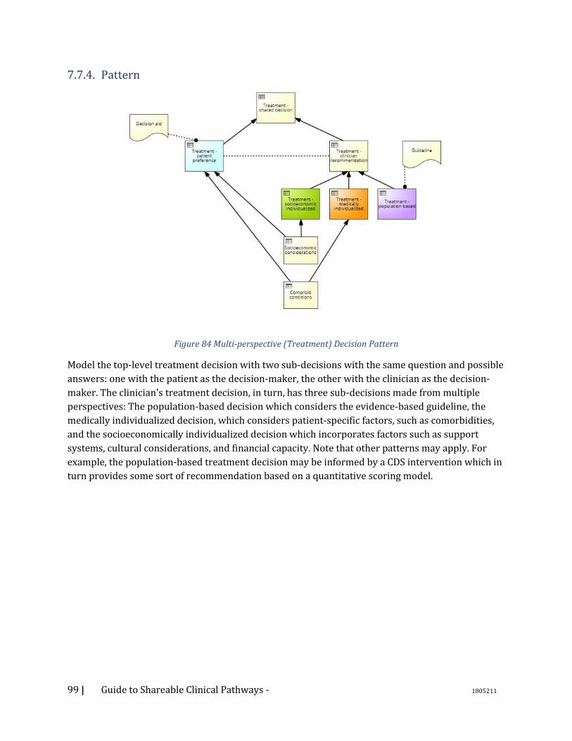
99 | Guide to Shareable Clinical Pathways - 1805211
7.7.4. Pattern
Figure 84 Multi-perspective (Treatment) Decision Pattern
Model the top-level treatment decision with two sub-decisions with the same question and possible
answers: one with the patient as the decision-maker, the other with the clinician as the decision-
maker. The clinician's treatment decision, in turn, has three sub-decisions made from multiple
perspectives: The population-based decision which considers the evidence-based guideline, the
medically individualized decision, which considers patient-specific factors, such as comorbidities,
and the socioeconomically individualized decision which incorporates factors such as support
systems, cultural considerations, and financial capacity. Note that other patterns may apply. For
example, the population-based treatment decision may be informed by a CDS intervention which in
turn provides some sort of recommendation based on a quantitative scoring model.
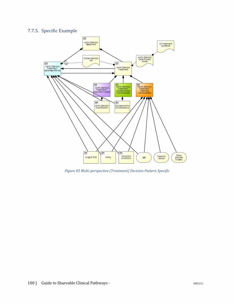
100 | Guide to Shareable Clinical Pathways - 1805211
7.7.5. Specific Example
Figure 85 Multi-perspective (Treatment) Decision Pattern Specific

101 | Guide to Shareable Clinical Pathways - 1805211
7.8. DMN: Team-based decision 7.8.1. Description Clinicians often make ‘chains’ of decisions: complex cognitive processes such that the output of each
decision not only informs the next decision, but also what decisions to make next.
The chain is implicitly aimed to optimize the cognitive load, so that attention is only focused on
what matters, when it matters, and if and only if matters.
For example, a guideline for the treatment of atrial fibrillation may recommend putting a patient on
a long term anticoagulant regime. A physician will eventually have to place an order, which requires
a level of detail regarding the actual drug and (among others) its form and dose and schedule. Way
before then, however, the physician will determine whether the patient is an actual candidate for
anticoagulation and only then what kind of anticoagulant to administer (e.g. warfarin vs oral
anticoagulant).
7.8.2. Problem Even if decision models can be refactored without altering the overall semantics, some formulations can be more efficient than others. Part of what is called ‘expertise’ consists in being able to optimize cognitive processes. In a decision model, this can be reflected by virtue of identifying, and properly separating, the decisions that deal with the problem at hand from those decisions that guide the cognitive process. The optimal cognitive process can then be represented explicitly in a variety of ways. We propose two alternative representations, one based on BPMN and one based on CMMN. In this sense, this pattern specializes the Workflow-Interleaved Decision one. A BPMN model, prescriptive by nature, can be used to specify the optimal, ‘natural’ flow of decisions. In this model, each decision should be made, and made at a specific point in time (at least relatively to the other decisions). In a CMMN model, adaptive by nature, the ‘control’ decision determine the applicability (at planning time when the case is opened) and/or the eligibility (reactively, during the execution of the case) of other decisions.
7.8.3. Applicability • A complex decision problem can be decomposed into a tree of Decisions • Intermediary decisions influence what decision to make next
7.8.4. Specific Example In the anticoagulation scenario, the clinician tries to determine as soon as possible whether the patient is eligible for anticoagulation. If this is not the case, no more effort will be invested in further trying to determine the details of an anticoagulation therapy that will never be prescribed. In this sense, this first decision is an ‘applicability’ decision. The second decision, a ‘choice’ decision, resolves some of the degrees of freedom of the problem (i.e. which anticoagulant to use), but not e.g. the dose and schedule. In fact, it does not make sense to even frame the problem of dosing the drug until the choice of which drug has been made.
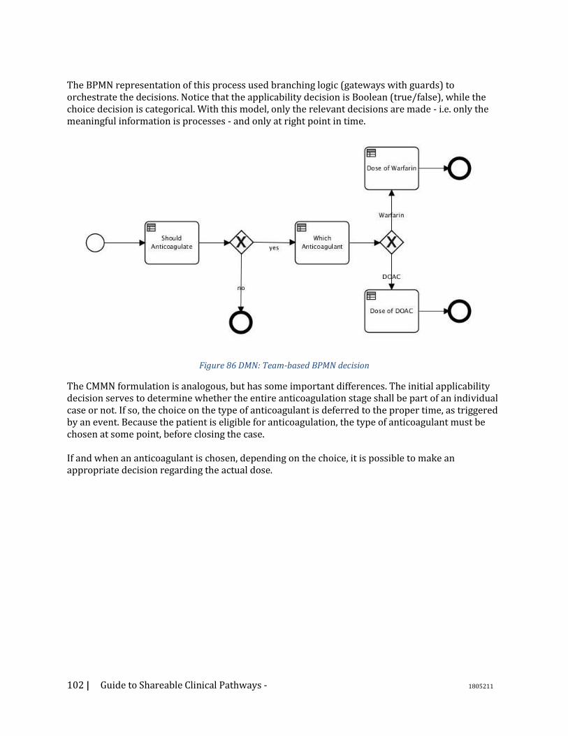
102 | Guide to Shareable Clinical Pathways - 1805211
The BPMN representation of this process used branching logic (gateways with guards) to orchestrate the decisions. Notice that the applicability decision is Boolean (true/false), while the choice decision is categorical. With this model, only the relevant decisions are made - i.e. only the meaningful information is processes - and only at right point in time.
Figure 86 DMN: Team-based BPMN decision
The CMMN formulation is analogous, but has some important differences. The initial applicability decision serves to determine whether the entire anticoagulation stage shall be part of an individual case or not. If so, the choice on the type of anticoagulant is deferred to the proper time, as triggered by an event. Because the patient is eligible for anticoagulation, the type of anticoagulant must be chosen at some point, before closing the case. If and when an anticoagulant is chosen, depending on the choice, it is possible to make an appropriate decision regarding the actual dose.
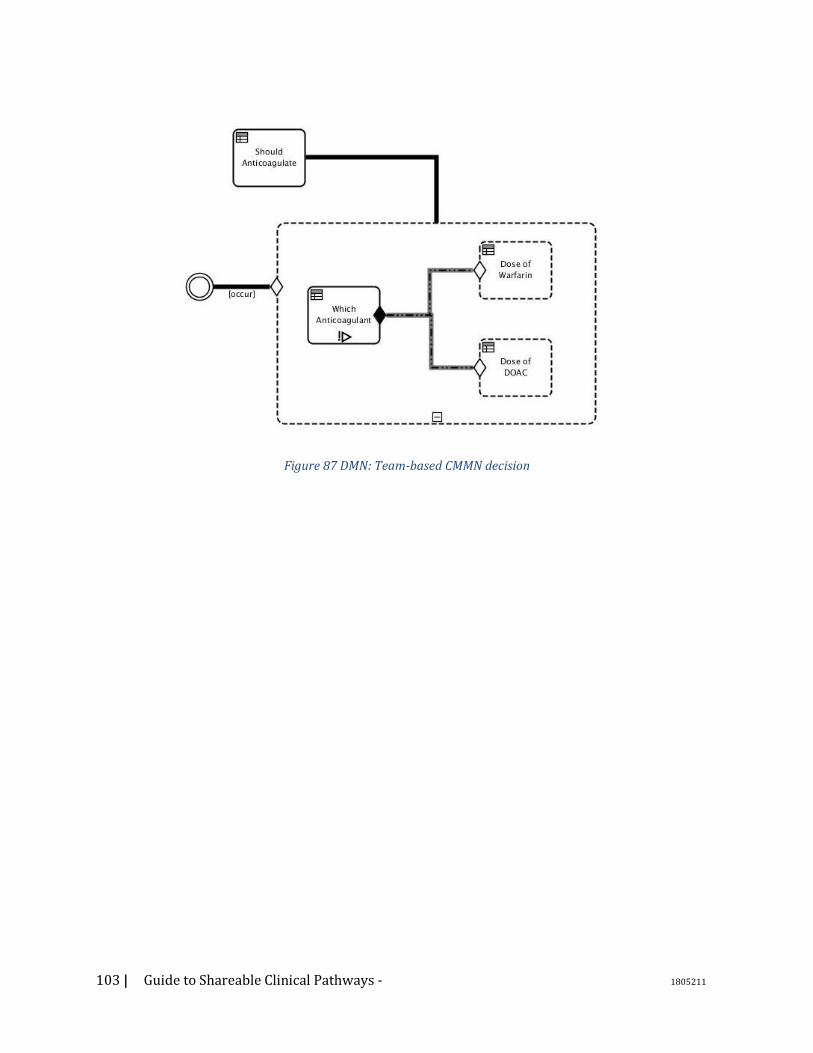
103 | Guide to Shareable Clinical Pathways - 1805211
Figure 87 DMN: Team-based CMMN decision
104 | Guide to Shareable Clinical Pathways - 1805211
8. Appendix C – Sustainment and Governance Whether developing process models for use within your own institution, or as a contributor or consumer that is part of a broader ecosystem, the role of governance and model management within the environment in which you work will have direct impacts on not only how models are created, but how they are tagged, versioned, and managed. While this section will make allusions to the formalities of model management within an ecosystem – internal or community-based – it is not intended to document all of the governance required to support the full model management lifecycle. There are more extensive resources better suited to that need. Instead, this section will attempt to highlight the importance of the broader context of model management to the individual consumer or contributor, rationalizing why those steps are important and calling out key elements for consideration as part of your modeling activities.
8.1. Governance Goals Process models are not created in a vacuum: they rely heavily on industry best practices, internal institutional approaches and workflows, relationships to other activities, constraints such as performance and quality measures, and so on. Moreover, when documenting models, we are often extending or adapting other work, creating new derivatives or variants on something in place today, whether that was invented locally or adapted from elsewhere. Governance activities exist to maintain confidence and integrity of the models being produced and consumed. This typically includes activity steps to assure that the artifacts contributed are accurate, documented, fit-for-purpose, and managed with integrity. The extent of rigor and formality associated with governance processes typically relates to the organizational size and complexity, the volume of assets being governed, the number of stakeholders involved in the activities, and the clarity of ownership around the content. As you create and consume models, please bear the following in mind: For INTRA-INSTITUTIONAL efforts:
1. Governance is typically defined by policy
2. Specificity around the description of artifacts may or may not be rigorous,
depending upon the strength of the vernacular within the organization, its size,
and institutional variability (or lack thereof)
3. Stakeholders may be defined by specific job titles, roles, or even individuals’
names
For ECOSYSTEM/EXTERNAL efforts: 1. There may be contribution policies affecting the ability to post models. These
may be quality constraints of the ecosystem itself, or institutional policies
affecting what can be contributed.
2. Management of intellectual property is a paramount importance (e.g., requiring
certain distribution licensing, articulating IP constraints and compatibilities,
limitations on use or derivative use, and so on)
3. Management of versioning, interdependencies among contributions, and a
taxonomy of contributed content is key to asset management
4. Use of common expression languages (such as BPMN/CMMN/DMN)
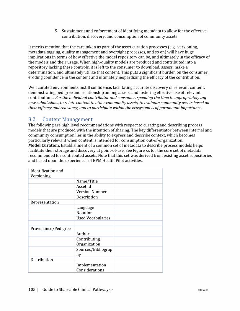
105 | Guide to Shareable Clinical Pathways - 1805211
5. Sustainment and enforcement of identifying metadata to allow for the effective
contribution, discovery, and consumption of community assets
It merits mention that the care taken as part of the asset curation processes (e.g., versioning, metadata tagging, quality management and oversight processes, and so on) will have huge implications in terms of how effective the model repository can be, and ultimately in the efficacy of the models and their usage. When high-quality models are produced and contributed into a repository lacking these controls, it is left to the consumer to download, assess, make a determination, and ultimately utilize that content. This puts a significant burden on the consumer, eroding confidence in the content and ultimately jeopardizing the efficacy of the contribution. Well curated environments instill confidence, facilitating accurate discovery of relevant content, demonstrating pedigree and relationship among assets, and fostering effective use of relevant contributions. For the individual contributor and consumer, spending the time to appropriately tag new submissions, to relate content to other community assets, to evaluate community assets based on their efficacy and relevancy, and to participate within the ecosystem is of paramount importance.
8.2. Content Management The following are high level recommendations with respect to curating and describing process models that are produced with the intention of sharing. The key differentiator between internal and community consumption lies in the ability to express and describe context, which becomes particularly relevant when content is intended for consumption out-of-organization. Model Curation. Establishment of a common set of metadata to describe process models helps facilitate their storage and discovery at point-of-use. See Figure xx for the core set of metadata recommended for contributed assets. Note that this set was derived from existing asset repositories and based upon the experiences of BPM Health Pilot activities.
Identification and Versioning
Name/Title Asset Id Version Number Description Representation Language Notation Used Vocabularies Provenance/Pedigree Author Contributing
Organization
Sources/Bibliography
Distribution Implementation
Considerations
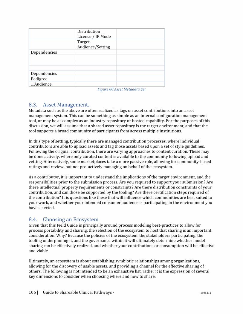
106 | Guide to Shareable Clinical Pathways - 1805211
Distribution License / IP Mode
Target Audience/Setting
Dependencies Dependencies Pedigree …Audience
Figure 88 Asset Metadata Set
8.3. Asset Management. Metadata such as the above are often realized as tags on asset contributions into an asset management system. This can be something as simple as an internal configuration management tool, or may be as complex as an industry repository or hosted capability. For the purposes of this discussion, we will assume that a shared asset repository is the target environment, and that the tool supports a broad community of participants from across multiple institutions. In this type of setting, typically there are managed contribution processes, where individual contributors are able to upload assets and tag those assets based upon a set of style guidelines. Following the original contribution, there are varying approaches to content curation. These may be done actively, where only curated content is available to the community following upload and vetting. Alternatively, some marketplaces take a more passive role, allowing for community-based ratings and review, but not pro-actively managing on behalf of the ecosystem. As a contributor, it is important to understand the implications of the target environment, and the responsibilities prior to the submission process. Are you required to support your submission? Are there intellectual property requirements or constraints? Are there distribution constraints of your contribution, and can those be supported by the tooling? Are there certification steps required of the contribution? It is questions like these that will influence which communities are best suited to your work, and whether your intended consumer audience is participating in the environment you have selected.
8.4. Choosing an Ecosystem Given that this Field Guide is principally around process modeling best-practices to allow for process portability and sharing, the selection of the ecosystem to host that sharing is an important consideration. Why? Because the policies of the ecosystem, the stakeholders participating, the tooling underpinning it, and the governance within it will ultimately determine whether model sharing can be effectively realized, and whether your contributions or consumption will be effective and viable. Ultimately, an ecosystem is about establishing symbiotic relationships among organizations, allowing for the discovery of usable assets, and providing a channel for the effective sharing of others. The following is not intended to be an exhaustive list, rather it is the expression of several key dimensions to consider when choosing where and how to share:

107 | Guide to Shareable Clinical Pathways - 1805211
Ecosystem Legitimacy: Is this a community of the “right” organizations? Do they have institutional creditability? Are they trusted within the industry? Do we have confidence in their objectives and policies? Are we comfortable working with them?
Community Meritocracy: Are contributions within the community based upon their efficacy and quality? Is the infrastructure in place to allow the ecosystem to decide what is good or not good? Do any institutions hold undue influence or sway, potentially to the adverse benefit of the community?
Openness and Transparency: Are policies in place to allow for the discovery of activities underway, and/or the ability to create new or competing activities? Are governance rules clearly articulated and consistently applied to all community members? Does the community favor a specific vendor or is it a “level playing field?”
Governance: Are rules associated with contributions, quality management, asset management, and distribution clearly articulated and consistently enforced? Are oversight activities and bodies open to all participants, either directly or in a representational fashion (e.g., elected members). Are governance rules objective and evidence-based? Tooling: Are tools being made available to the membership and consuming community? Are the tools home-grown or commercially available? Is the tooling environment or infrastructure open, and/or does it allow for effective inter-operation with your institutional needs?
Business Model Compatibility: Does the ecosystem align or complement with your institutional needs in terms of business and/or revenue model? (e.g., some ecosystems serve as a distribution/licensing model, such as the Apple App Store). Does the ecosystem support/enforce your asset distribution requirements? Is the ecosystem sustainable? Ultimately, the selection of an ecosystem has tremendous import on the viability and efficacy of model sharing. Ideally, your selected channel will meet all of the above requirements, but in reality different communities will have inherent strengths and weaknesses. An honest assessment of the above, taking into account risks and organizational needs, will help you to make well-informed decisions.
108 | Guide to Shareable Clinical Pathways - 1805211
9. Appendix D – Glossary of Terms Activity - An Activity is the term for the work that company performs in a Process. An Activity can be atomic or non-atomic (compound). Business Process Modeling and Notation (BPMN) - BPMN is an approved OMG specification. The BPMN specification provides a graphical notation for specifying business processes. See http://www.omg.org/bpmn/index.html for more information about BPMN and its specification. Case Management Model and Notation (CMMN) – CMMN is an approved OMG specification that is compatible with and complementary to the OMG BPMN specification and the OMG DMN specification. CMMN defines a common meta-model and graphical notations for expressing a model developed using the CMMN Standard. A Case is a proceeding involving the care of a patient or a healthcare business transaction to achieve a desired outcome. CMMN provides concepts to Business Process Models by adding such concepts as Roles and Activity Listeners. See http://www.omg.org/spec/CMMN/1.1/ for the complete CMMN specification. Choreography – Within BPMN defines the way business participants coordinate their interactions and exchange of information between involved parties. The coordination of interaction is defined by how each party interacts with their counterpart; there is no central orchestration or control. Clinical Pathways – are workflow definitions that outline the necessary steps and goals in the care of patients under a set of defined conditions. Clinical Pathways can be fully described using a combination of BPMN, CMMN, and DMN Notations. Clinical Decision System (CDS) –Clinical Decision Systems encompasses a variety of tools to increase quality of outcomes generally at point of care. Data Object - Data Objects provide information about what Activities require to be performed and/or what they produce. There are two types of Data Objects; Data Input and Data Output. Decision Modeling Notation (DMN) – DMN is an approved OMG specification that is compatible with and complementary to the OMG BPMN specification and the OMG CMMN specification. DMN provides a meta-model and a graphic notation to document decisions events found in processes. The DMN notation is designed to be useable alongside the standard BPMN business process notation. See http://www.omg.org/spec/DMN/1.1/ for the complete DMN specification.
Dependency Inversion Principle – NEED Reference - Apply Cold Treatment / Apply Cold Treatment to Left Ankle EHR – EHR refers to an Electronic Healthcare Record system used to capture and store healthcare information. Electronic Medical Record (EMR) systems are synonymous with EHR systems. FHIR (Fast Healthcare Interoperability Resources)– FHIR is a standard for exchanging healthcare information electronically (taken from FHIR page). See www.hl7.org/fhir for more information. HSSP (Healthcare Services Specification Platform) – HSSP is a joint initiative of the OMG and the Health Level 7 standards organizations. The objective of the HSSP project is to create useful, usable
109 | Guide to Shareable Clinical Pathways - 1805211
healthcare standards that define functions, semantics, and technology bindings supportive of system-level interoperability for the healthcare industry. See https://en.wikipedia.org/wiki/Healthcare_Services_Specification_Project for more information. HSPC (Healthcare Services Platform Consortium) – HSPC is a provider-led and vendor-involved consortium dedicated to establishing a scalable, truly interoperable data and services architecture for healthcare. See www.hspconsortium.org for more information. HL7 (Health Level Seven International – The ANSI-accredited standards developing organization dedicated to providing a comprehensive framework and related standards for the exchange, integration, sharing, and retrieval of electronic health information that supports clinical practice and the management, delivery and evaluation of health services. IHE (Integrating the Healthcare Environment) – A non-profit organization who sponsors initiatives by which the healthcare industry can improve the way computer systems share information. OMG (Object Management Group) – The Object Management Group® (OMG®) is an international, open membership, not-for-profit technology standards consortium. OMG standards are driven by vendors, end-users, academic institutions and government agencies. OMG Task Forces develop enterprise integration standards for a wide range of technologies and an even wider range of industries. The Healthcare Domain Task Force is the working group for the healthcare industry within the OMG. See www.omg.org for more information about the OMG.

110 | Guide to Shareable Clinical Pathways - 1805211
10. Appendix E – Hello Patient Models
Figure 89 Hello Patient BPMN
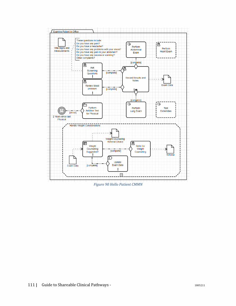
111 | Guide to Shareable Clinical Pathways - 1805211
Figure 90 Hello Patient CMMN
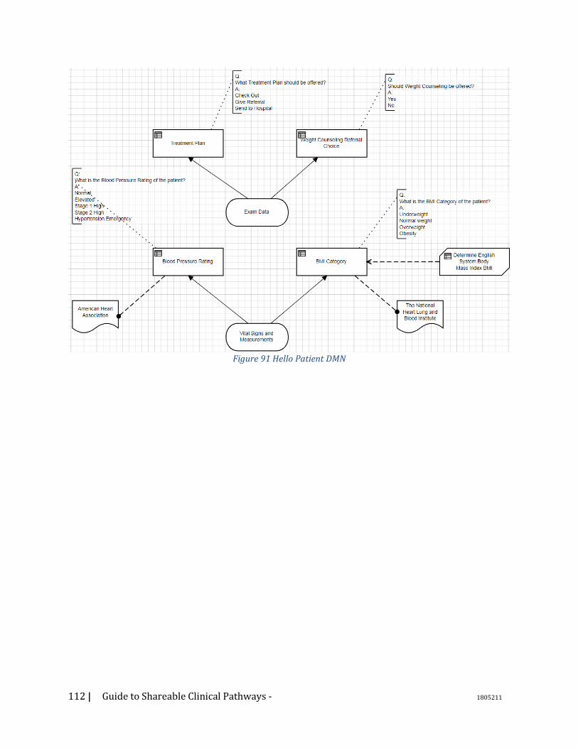
112 | Guide to Shareable Clinical Pathways - 1805211
Figure 91 Hello Patient DMN
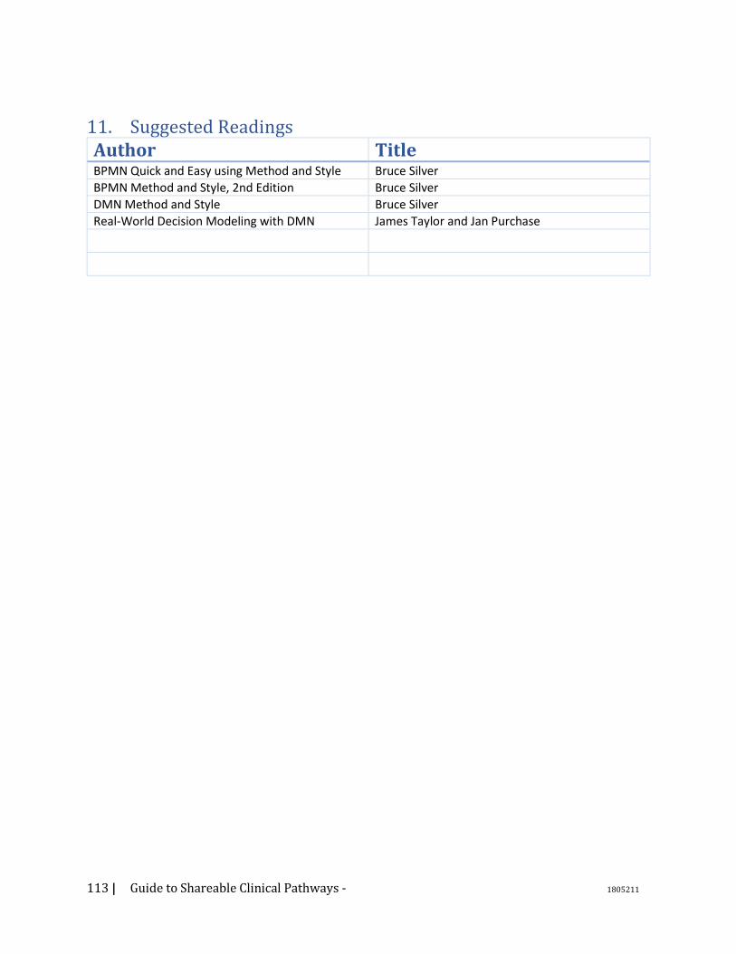
113 | Guide to Shareable Clinical Pathways - 1805211
11. Suggested Readings Author Title BPMN Quick and Easy using Method and Style Bruce Silver BPMN Method and Style, 2nd Edition Bruce Silver DMN Method and Style Bruce Silver Real-World Decision Modeling with DMN James Taylor and Jan Purchase
114 | Guide to Shareable Clinical Pathways - 1805211
12. Future Work 1. Would it make sense to touch on six
sigma lean principles. The use of Lean seems to be something that is being leveraged within many healthcare organizations. Introducing clinical personnel to BPMN and DMN would build on top of any LEAN knowledge that they may have.

115 | Guide to Shareable Clinical Pathways - 1805211