field performance of a slimline turbomist evaporator under
TRANSCRIPT
Prepared by:
United States Department of Energy
Savannah River Site
Field Performance of a Slimline Turbomist Evaporator under Southeastern U. S. Climate Conditions (U)
WSRC–RP–2003-00429
Revision 0
October 2003
UNCLASSIFIED Does Not Contain Unclassified Nuclear Information (UCNI)
ADC and Reviewing Official
M. K. Harris, Manager Geo-Modeling
Environmental Restoration Technology Section
Westinghouse Savannah River Company LLC Savannah River Site Aiken, SC 29808 Prepared for the U. S. Department of Energy Under Contract No. DE-AC09-96SR18500
This document was prepared in conjunction with work accomplished under Contract No.DE-AC09-96SR18500 with the U. S. Department of Energy.
DISCLAIMER
This report was prepared as an account of work sponsored by an agency of the United StatesGovernment. Neither the United States Government nor any agency thereof, nor any of theiremployees, makes any warranty, express or implied, or assumes any legal liability or responsibilityfor the accuracy, completeness, or usefulness of any information, apparatus, product or processdisclosed, or represents that its use would not infringe privately owned rights. Reference herein toany specific commercial product, process or service by trade name, trademark, manufacturer, orotherwise does not necessarily constitute or imply its endorsement, recommendation, or favoring bythe United States Government or any agency thereof. The views and opinions of authors expressedherein do not necessarily state or reflect those of the United States Government or any agencythereof.
This report has been reproduced directly from the best available copy.
Available for sale to the public, in paper, from: U.S. Department of Commerce, National TechnicalInformation Service, 5285 Port Royal Road, Springfield, VA 22161,phone: (800) 553-6847,fax: (703) 605-6900email: [email protected] ordering: http://www.ntis.gov/help/index.asp
Available electronically at http://www.osti.gov/bridgeAvailable for a processing fee to U.S. Department of Energy and its contractors, in paper, from: U.S.Department of Energy, Office of Scientific and Technical Information, P.O. Box 62, Oak Ridge, TN37831-0062,phone: (865)576-8401,fax: (865)576-5728email: [email protected]
Field Performance of a Slimline Turbomist Evaporator WSRC-RP-2003-00429 under Southeastern U. S. Climate Conditions Revision 0 October 2003 Page ii

Field Performance of a Slimline Turbomist Evaporator WSRC-RP-2003-00429 under Southeastern U. S. Climate Conditions Revision 0 October 2003 Page iii
Approvals:
Field Performance of a Slimline Turbomist Evaporator WSRC-RP-2003-00429 under Southeastern U. S. Climate Conditions Revision 0 October 2003 Page iv
Table of Contents
1.0 Introduction............................................................................................................................1 2.0 Evaporation principles ..........................................................................................................3 3.0 Experiment design and setup................................................................................................6 4.0 Field testing and data...........................................................................................................12 5.0 Predictive model...................................................................................................................21 6.0 Forecast evaporation rates ..................................................................................................25 7.0 Summary and conclusions...................................................................................................26 8.0 References.............................................................................................................................26
Tables
Table 1 Adiabatic saturation calculation for SRS annual average climate conditions. ...4 Table 2 Average climate conditions at the SRS over various time periods.......................5 Table 3 Spray rate projected for various nozzle core and orifice plate selections. ..........8 Table 4 Summary of Turbo-Mist field tests. ......................................................................14 Table 5 Least-squares parameter estimation results.........................................................23 Table 6 Normalized evaporation and spray rates..............................................................23
Figures
Figure 1 Vendor photographs of Slimline Turbo-Mist evaporator.....................................2 Figure 2 Evaporative cooling potential as a function of temperature and relative
humidity. ....................................................................................................................5 Figure 3 Location of Turbo-Mist field test.............................................................................9 Figure 4 Surveyed grid system for placement of fallback collection devices....................10 Figure 5 Collection devices selected for measuring spray fallback ...................................10 Figure 6 Rain gauge brands procured for SRS field testing. .............................................11 Figure 7 Simplified Piping Configuration............................................................................11 Figure 8 Cross-plot of Clear and Yellow rain gauge data collected during field
testing on 3/31/03.....................................................................................................15 Figure 9 Cross-plot of White and Yellow rain gauge data collected during field
testing on 3/31/03.....................................................................................................15 Figure 10 Cross-plot of absorbent pad and "best" rain gauge fallback data
collected during field testing on 3/31/03................................................................16 Figure 11 Cross-plot of absorbent pad and rain gauge data collected from all
applicable field tests................................................................................................16 Figure 12 Spray fallback pattern for Turbo-Mist field test on 3/31/03...............................17 Figure 13 Spray fallback pattern for Turbo-Mist field test on 4/29/03...............................17 Figure 14 Spray fallback pattern for Turbo-Mist field test on 5/1/03.................................18 Figure 15 Spray fallback pattern for Turbo-Mist field test on 5/14/03...............................18
Field Performance of a Slimline Turbomist Evaporator WSRC-RP-2003-00429 under Southeastern U. S. Climate Conditions Revision 0 October 2003 Page v Figure 16 Spray fallback pattern for Turbo-Mist field test on 6/25/03...............................19 Figure 17 Spray fallback pattern for Turbo-Mist field test on 6/26/03...............................19 Figure 18 Spray fallback pattern for Turbo-Mist field test on 7/24/03...............................20 Figure 19 Spray fallback pattern for Turbo-Mist field test on 8/11/03...............................20 Figure 20 Normalized evaporation and spray rates..............................................................24
Appendices
Appendix A – Data and analysis for Turbo-Mist field test on 3/31/03....................................27 Appendix B – Data and analysis for Turbo-Mist field test on 4/29/03....................................31 Appendix C – Data and analysis for Turbo-Mist field test on 5/1/03......................................35 Appendix D – Data and analysis for Turbo-Mist field test on 5/14/03....................................39 Appendix E – Data and analysis for Turbo-Mist field test on 6/25/03....................................43 Appendix F – Data and analysis for Turbo-Mist field test on 6/26/03 ....................................47 Appendix G – Data and analysis for Turbo-Mist field test on 7/24/03 ...................................51 Appendix H – Data and analysis for Turbo-Mist field test on 8/11/03 ...................................55
Field Performance of a Slimline Turbomist Evaporator WSRC-RP-2003-00429 under Southeastern U. S. Climate Conditions Revision 0 October 2003 Page 1
Field Performance of a Slimline Turbomist Evaporator under Southeastern U. S. Climate Conditions
1.0 INTRODUCTION
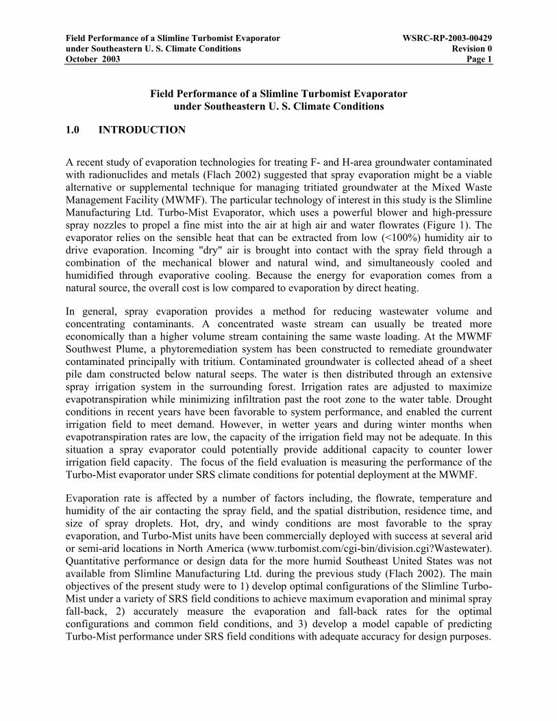
A recent study of evaporation technologies for treating F- and H-area groundwater contaminated with radionuclides and metals (Flach 2002) suggested that spray evaporation might be a viable alternative or supplemental technique for managing tritiated groundwater at the Mixed Waste Management Facility (MWMF). The particular technology of interest in this study is the Slimline Manufacturing Ltd. Turbo-Mist Evaporator, which uses a powerful blower and high-pressure spray nozzles to propel a fine mist into the air at high air and water flowrates (Figure 1). The evaporator relies on the sensible heat that can be extracted from low (<100%) humidity air to drive evaporation. Incoming "dry" air is brought into contact with the spray field through a combination of the mechanical blower and natural wind, and simultaneously cooled and humidified through evaporative cooling. Because the energy for evaporation comes from a natural source, the overall cost is low compared to evaporation by direct heating.
In general, spray evaporation provides a method for reducing wastewater volume and concentrating contaminants. A concentrated waste stream can usually be treated more economically than a higher volume stream containing the same waste loading. At the MWMF Southwest Plume, a phytoremediation system has been constructed to remediate groundwater contaminated principally with tritium. Contaminated groundwater is collected ahead of a sheet pile dam constructed below natural seeps. The water is then distributed through an extensive spray irrigation system in the surrounding forest. Irrigation rates are adjusted to maximize evapotranspiration while minimizing infiltration past the root zone to the water table. Drought conditions in recent years have been favorable to system performance, and enabled the current irrigation field to meet demand. However, in wetter years and during winter months when evapotranspiration rates are low, the capacity of the irrigation field may not be adequate. In this situation a spray evaporator could potentially provide additional capacity to counter lower irrigation field capacity. The focus of the field evaluation is measuring the performance of the Turbo-Mist evaporator under SRS climate conditions for potential deployment at the MWMF.
Evaporation rate is affected by a number of factors including, the flowrate, temperature and humidity of the air contacting the spray field, and the spatial distribution, residence time, and size of spray droplets. Hot, dry, and windy conditions are most favorable to the spray evaporation, and Turbo-Mist units have been commercially deployed with success at several arid or semi-arid locations in North America (www.turbomist.com/cgi-bin/division.cgi?Wastewater). Quantitative performance or design data for the more humid Southeast United States was not available from Slimline Manufacturing Ltd. during the previous study (Flach 2002). The main objectives of the present study were to 1) develop optimal configurations of the Slimline Turbo-Mist under a variety of SRS field conditions to achieve maximum evaporation and minimal spray fall-back, 2) accurately measure the evaporation and fall-back rates for the optimal configurations and common field conditions, and 3) develop a model capable of predicting Turbo-Mist performance under SRS field conditions with adequate accuracy for design purposes.

Field Performance of a Slimline Turbomist Evaporator WSRC-RP-2003-00429 under Southeastern U. S. Climate Conditions Revision 0 October 2003 Page 2
Figure 1 Vendor photographs of Slimline Turbo-Mist evaporator.

Field Performance of a Slimline Turbomist Evaporator WSRC-RP-2003-00429 under Southeastern U. S. Climate Conditions Revision 0 October 2003 Page 3 2.0 EVAPORATION PRINCIPLES
When “dry” (<100% humidity) air is brought into contact with liquid water, with no heat transfer to or from the overall system, liquid evaporates and air is cooled until thermodynamic equilibrium is reached (100% humidity). Such an operation is termed “adiabatic saturation”, and is the principle behind “swamp coolers” used for residential cooling in the Southwest US and agricultural cooling (e.g. poultry houses). The energy required to vaporize liquid water (latent heat of vaporization) is extracted from dry air through cooling (sensible heat). The amount of cooling as a function of temperature and relative humidity of the incoming air stream can be determined through application of the first law of thermodynamics, which states that enthalpy is conserved in a open system (cf. Reynolds and Perkins 1977). With minor approximation, the adiabatic saturation process can be described by:
(1) ( ) ( ) *outoutwainwa
*in hhhhhh =γ+=γ+=
where = enthalpy of moist air per unit mass of dry air, = enthalpy of dry air, enthalpy of water vapor,
*h ah wh =γ = specific humidity or humidity ratio (Reynolds and Perkins 1977
section 10-4). The thermodynamic properties of moist air can be readily computed from an ASHRAE handbook (e.g. American Society of Heating, Refrigerating and Air-Conditioning Engineers 1985) for equivalent source.
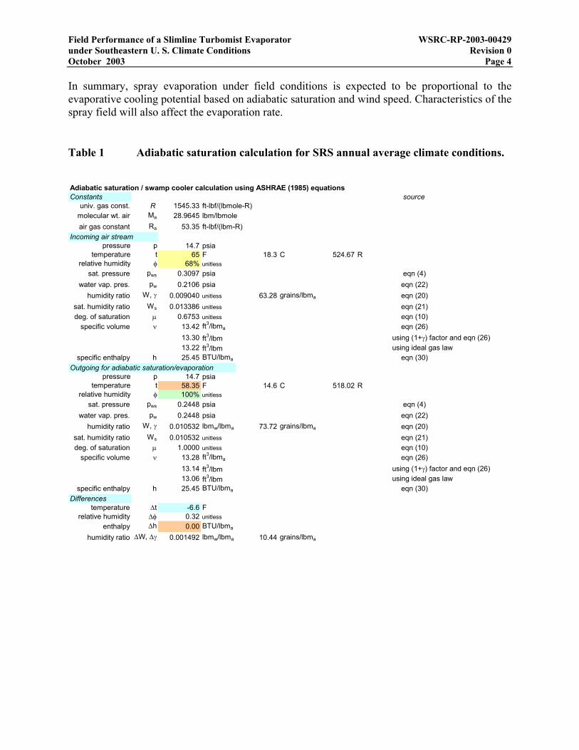
An example calculation is shown in Table 1, where the temperature and humidity of the incoming air stream have been set to the annual averages at the SRS, 65F and 68% (Hunter and Tatum 1997). For these conditions, the evaporative cooling is 6.6 ºF. Figure 2 shows contours of constant evaporative cooling degrees resulting from various combinations of temperature and relative humidity. As illustrated by the plot, higher temperature and lower humidity produce more cooling and corresponding evaporation. Also shown in Figure 2 are seasonal average values of temperature and humidity at the SRS. Table 2 identifies the basis for these values and provides monthly average values as well.
Spray evaporation under atmospheric conditions is expected to be proportional to the cooling and evaporation amounts computed under adiabatic saturation conditions (Figure 2). For evaporation to be sustained, dry air (and water) must be continuously supplied to replenish the system. An energy balance expanding on equation (1) indicates that evaporation of initially dry air and evaporation of liquid water is proportional to the mass flowrate of dry air delivered to the system. For atmospheric spray evaporation, fresh air is delivered to the spray field through natural winds. Thus, the spray evaporation rate is also expected to be proportional to local wind speed. The overall dimensions of the spray field, and the distribution, residence time, and size of spray droplets within, are also expected to affect the evaporation rate. For example, the flowrate of dry air contacting the spray field is proportional to the cross-sectional area perpendicular to wind direction, in addition to wind speed.
Field Performance of a Slimline Turbomist Evaporator WSRC-RP-2003-00429 under Southeastern U. S. Climate Conditions Revision 0 October 2003 Page 4 In summary, spray evaporation under field conditions is expected to be proportional to the evaporative cooling potential based on adiabatic saturation and wind speed. Characteristics of the spray field will also affect the evaporation rate.
Table 1 Adiabatic saturation calculation for SRS annual average climate conditions.
Adiabatic saturation / swamp cooler calculation using ASHRAE (1985) equationsConstants source
univ. gas const. R 1545.33 ft-lbf/(lbmole-R)molecular wt. air Ma 28.9645 lbm/lbmoleair gas constant Ra 53.35 ft-lbf/(lbm-R)
Incoming air streampressure p 14.7 psia
temperature t 65 F 18.3 C 524.67 Rrelative humidity φ 68% unitless
sat. pressure pws 0.3097 psia eqn (4)water vap. pres. pw 0.2106 psia eqn (22)
humidity ratio W, γ 0.009040 unitless 63.28 grains/lbma eqn (20)sat. humidity ratio Ws 0.013386 unitless eqn (21)deg. of saturation µ 0.6753 unitless eqn (10)
specific volume ν 13.42 ft3/lbma eqn (26)13.30 ft3/lbm using (1+γ) factor and eqn (26)13.22 ft3/lbm using ideal gas law
specific enthalpy h 25.45 BTU/lbma eqn (30)Outgoing for adiabatic saturation/evaporation
pressure p 14.7 psiatemperature t 58.35 F 14.6 C 518.02 R
relative humidity φ 100% unitlesssat. pressure pws 0.2448 psia eqn (4)
water vap. pres. pw 0.2448 psia eqn (22)humidity ratio W, γ 0.010532 lbmw/lbma 73.72 grains/lbma eqn (20)
sat. humidity ratio Ws 0.010532 unitless eqn (21)deg. of saturation µ 1.0000 unitless eqn (10)
specific volume ν 13.28 ft3/lbma eqn (26)13.14 ft3/lbm using (1+γ) factor and eqn (26)13.06 ft3/lbm using ideal gas law
specific enthalpy h 25.45 BTU/lbma eqn (30)Differences
temperature ∆t -6.6 Frelative humidity ∆φ 0.32 unitless
enthalpy ∆h 0.00 BTU/lbma
humidity ratio ∆W, ∆γ 0.001492 lbmw/lbma 10.44 grains/lbma
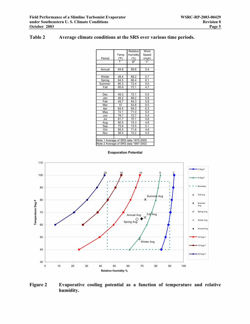
Field Performance of a Slimline Turbomist Evaporator WSRC-RP-2003-00429 under Southeastern U. S. Climate Conditions Revision 0 October 2003 Page 5 Table 2 Average climate conditions at the SRS over various time periods.
PeriodTemp (ºF)
Relative Humidity
(%)
Wind Speed (mph)
T 1 Ø2 V2
Annual 64.8 69.8 5.4
Winter 48.4 68.2 5.7Spring 64.5 66.4 6.1
Summer 80.3 72.4 5.0Fall 65.9 72.1 4.7
Dec 49.3 72.1 5.5Jan 46.2 68.2 5.8Feb 49.7 64.3 5.8Mar 57 63.8 6.5Apr 64.5 64.3 6.3May 72.1 71.0 5.5Jun 78.7 72.7 5.4Jul 81.7 70.1 4.8Aug 80.5 74.3 4.8Sep 75.6 72.5 5.1Oct 65.5 71.6 4.6Nov 56.5 72.2 4.5
Note 1 Average of SRS data 1970-2000Note 2 Average of SRS data 1997-2002
Evaporation Potential
Fall Avg
Summer Avg
Spring Avg
30
40
50
60
70
80
90
100
110
0 10 20 30 40 50 60 70 80 90 100
Relative Humidity %
Tem
pera
ture
Deg
F
2 Deg F
5 Deg F
Boundary
Fall Avg
SummerAvg
Spring Avg
Winter Avg
Annual Avg
10 Deg F
15 Deg F
20 Deg F
20 15 10 5 2
Winter Avg
Annual Avg
Figure 2 Evaporative cooling potential as a function of temperature and relative humidity.

Field Performance of a Slimline Turbomist Evaporator WSRC-RP-2003-00429 under Southeastern U. S. Climate Conditions Revision 0 October 2003 Page 6
3.0 EXPERIMENT DESIGN AND SETUP
As stated in the Introduction, one objective of field testing was to identify optimal configurations of the Slimline Turbo-Mist evaporator. For potential deployment at the MWMF over dry land, high evaporation and little or no fallback are considered to be optimal. The unit can be configured with No. 25 or No. 45 nozzle cores, and nozzle orifice plates ranging from D2 through D14 in increasing orifice diameter. An orifice blank can be used if no flow is desired from a nozzle port. The manifold ring accommodates 30 nozzles. Other potential configuration controls are the manifold supply pressure to nozzles, and the inclination of the blower output tube. The air flowrate is fixed by the electric motor speed. Because the number of field tests was limited by budget and schedule considerations, and spray fallback on the F-seepage basin cap was limited by regulators to 25 gpm, not all possible configurations could be tested.
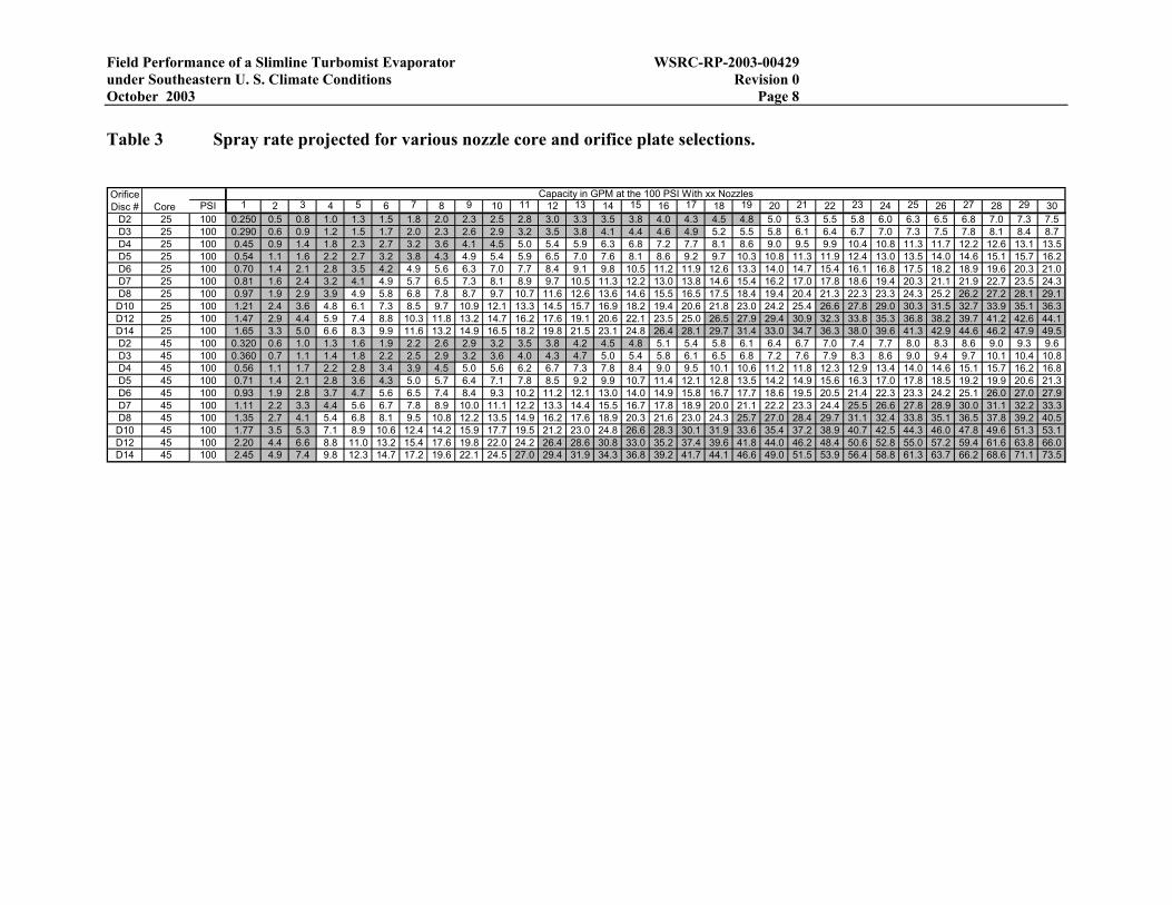
For SRS field testing, the air stream inclination was fixed at the maximum angle of 45 degrees to achieve maximum droplet loft, and the nozzle pressure was fixed at 100 psig. That left nozzle core and orifice plate selection as the attributes open for configuration optimization. Table 3 provides forecasts of the spray rate that will result from various combinations of number of nozzles, nozzle core and orifice plate at 100 psig based on vendor information. Spray rates less than or equal to 25 gpm (but at least 5 gpm) are highlighted as a conservative indicator of evaporator configurations that will avoid fallback exceeding 25 gpm. Turbo-Mist evaporation was roughly estimated from vendor information and engineering judgment to be on the order of 7 gpm for annual average SRS conditions in WSRC-TR-2002-00432. Optimal configurations were assumed to be those producing spray rates of this order of magnitude. From inspection of Table 3, 30 nozzles with orifice sizes D2 through D5 or D7 span the configurations that were anticipated to contain the optimal one for a given temperature and humidity.
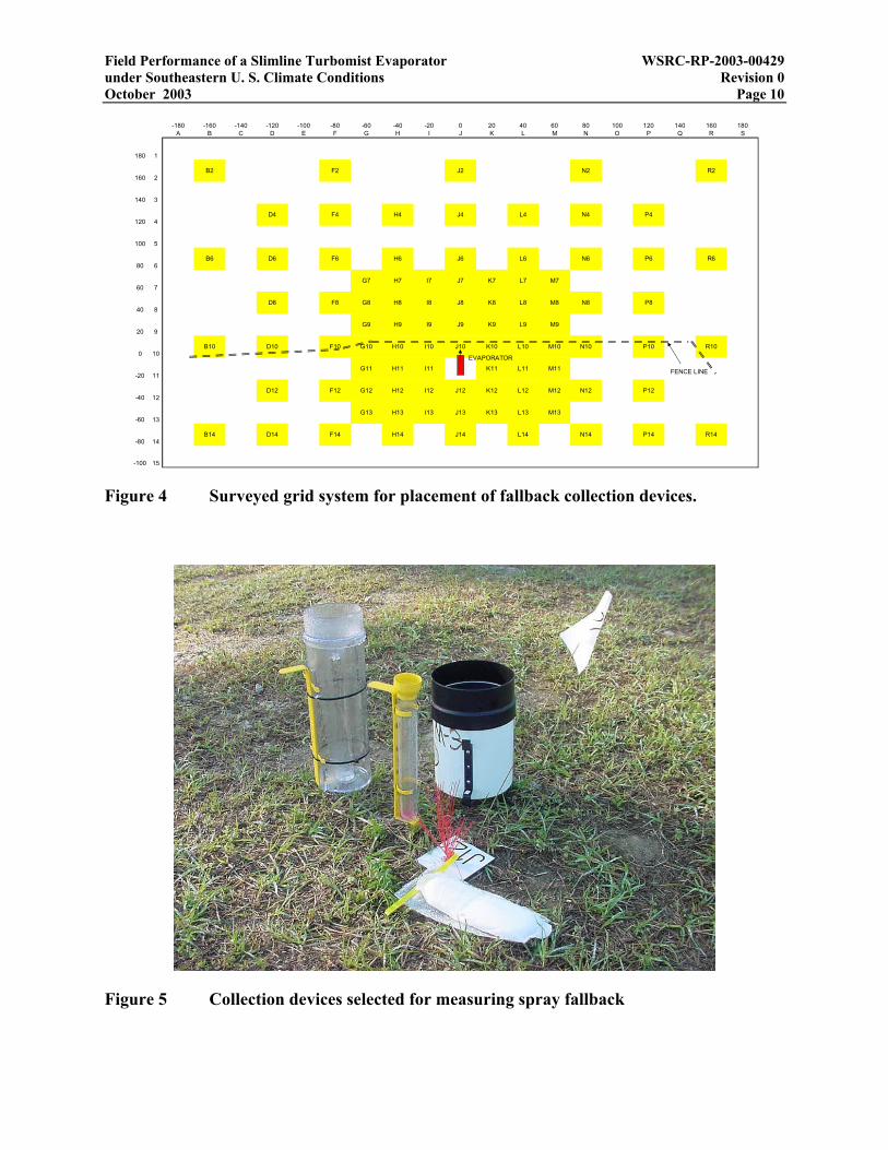
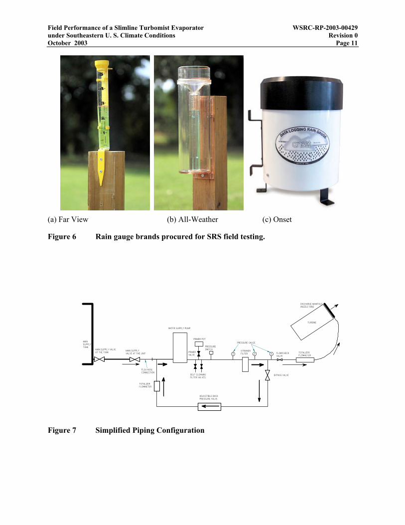
To measure evaporator performance for a particular nozzle configuration and weather condition, a grid of collection devices was deployed at the F-seepage basin cap (Figure 3) to measure spray fallback. The evaporation rate was then computed as the measured spray rate minus the fallback rate. The surveyed grid system is depicted in Figure 4. A 20 ft square spacing was used in the center of the grid. Collection devices could be deployed at a variety of grid locations to handle particular weather conditions, primarily wind speed and direction. To handle a wide range of potential fallback amounts over the duration of a field test, both rain gauges and absorbent pads were used (Figure 5). Early testing indicated that rain gauges have a practical detection limit of roughly 0.1”, and perhaps 0.2” is required for reasonable quantification. Absorbent pads can absorb and retain smaller amounts of fallback, approximately 0.2” and lower. Fallback is determined from the area, and dry and wet weights of the pad. Three brands of rain gauges (Figure 6) comprising two types (funnel/graduated cylinder and tipping bucket) were procured for the field testing. The Far View, All-Weather, and Onset gauges are commonly identified as the “Yellow”, “Clear” and “White” gauges, respectively, on procedure, data, and calculation sheets.
Normal deployment of the Slimline Turbo-Mist evaporator allows for up to 15’ of suction head, discharge flows in excess of 66 gpm, and additional water return for the self cleaning filter. To allow full flexibility for the testing, taking in consideration future deployments/test, the unit was
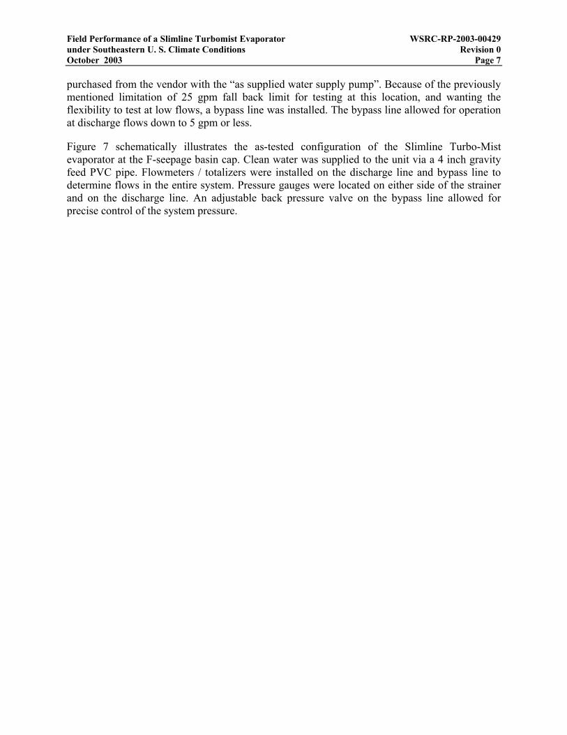
Field Performance of a Slimline Turbomist Evaporator WSRC-RP-2003-00429 under Southeastern U. S. Climate Conditions Revision 0 October 2003 Page 7 purchased from the vendor with the “as supplied water supply pump”. Because of the previously mentioned limitation of 25 gpm fall back limit for testing at this location, and wanting the flexibility to test at low flows, a bypass line was installed. The bypass line allowed for operation at discharge flows down to 5 gpm or less.
Figure 7 schematically illustrates the as-tested configuration of the Slimline Turbo-Mist evaporator at the F-seepage basin cap. Clean water was supplied to the unit via a 4 inch gravity feed PVC pipe. Flowmeters / totalizers were installed on the discharge line and bypass line to determine flows in the entire system. Pressure gauges were located on either side of the strainer and on the discharge line. An adjustable back pressure valve on the bypass line allowed for precise control of the system pressure.
Field Performance of a Slimline Turbomist Evaporator WSRC-RP-2003-00429 under Southeastern U. S. Climate Conditions Revision 0 October 2003 Page 8
Table 3 Spray rate projected for various nozzle core and orifice plate selections.
PSI 1 2 3 4 5 6 7 8 9 10 11 12 13 14 15 16 17 18 19 20 21 22 23 24 25 26 27 28 29 30
D2 25 100 0.250 0.5 0.8 1.0 1.3 1.5 1.8 2.0 2.3 2.5 2.8 3.0 3.3 3.5 3.8 4.0 4.3 4.5 4.8 5.0 5.3 5.5 5.8 6.0 6.3 6.5 6.8 7.0 7.3 7.5D3 25 100 0.290 0.6 0.9 1.2 1.5 1.7 2.0 2.3 2.6 2.9 3.2 3.5 3.8 4.1 4.4 4.6 4.9 5.2 5.5 5.8 6.1 6.4 6.7 7.0 7.3 7.5 7.8 8.1 8.4 8.7D4 25 100 0.45 0.9 1.4 1.8 2.3 2.7 3.2 3.6 4.1 4.5 5.0 5.4 5.9 6.3 6.8 7.2 7.7 8.1 8.6 9.0 9.5 9.9 10.4 10.8 11.3 11.7 12.2 12.6 13.1 13.5D5 25 100 0.54 1.1 1.6 2.2 2.7 3.2 3.8 4.3 4.9 5.4 5.9 6.5 7.0 7.6 8.1 8.6 9.2 9.7 10.3 10.8 11.3 11.9 12.4 13.0 13.5 14.0 14.6 15.1 15.7 16.2D6 25 100 0.70 1.4 2.1 2.8 3.5 4.2 4.9 5.6 6.3 7.0 7.7 8.4 9.1 9.8 10.5 11.2 11.9 12.6 13.3 14.0 14.7 15.4 16.1 16.8 17.5 18.2 18.9 19.6 20.3 21.0D7 25 100 0.81 1.6 2.4 3.2 4.1 4.9 5.7 6.5 7.3 8.1 8.9 9.7 10.5 11.3 12.2 13.0 13.8 14.6 15.4 16.2 17.0 17.8 18.6 19.4 20.3 21.1 21.9 22.7 23.5 24.3D8 25 100 0.97 1.9 2.9 3.9 4.9 5.8 6.8 7.8 8.7 9.7 10.7 11.6 12.6 13.6 14.6 15.5 16.5 17.5 18.4 19.4 20.4 21.3 22.3 23.3 24.3 25.2 26.2 27.2 28.1 29.1D10 25 100 1.21 2.4 3.6 4.8 6.1 7.3 8.5 9.7 10.9 12.1 13.3 14.5 15.7 16.9 18.2 19.4 20.6 21.8 23.0 24.2 25.4 26.6 27.8 29.0 30.3 31.5 32.7 33.9 35.1 36.3D12 25 100 1.47 2.9 4.4 5.9 7.4 8.8 10.3 11.8 13.2 14.7 16.2 17.6 19.1 20.6 22.1 23.5 25.0 26.5 27.9 29.4 30.9 32.3 33.8 35.3 36.8 38.2 39.7 41.2 42.6 44.1D14 25 100 1.65 3.3 5.0 6.6 8.3 9.9 11.6 13.2 14.9 16.5 18.2 19.8 21.5 23.1 24.8 26.4 28.1 29.7 31.4 33.0 34.7 36.3 38.0 39.6 41.3 42.9 44.6 46.2 47.9 49.5D2 45 100 0.320 0.6 1.0 1.3 1.6 1.9 2.2 2.6 2.9 3.2 3.5 3.8 4.2 4.5 4.8 5.1 5.4 5.8 6.1 6.4 6.7 7.0 7.4 7.7 8.0 8.3 8.6 9.0 9.3 9.6D3 45 100 0.360 0.7 1.1 1.4 1.8 2.2 2.5 2.9 3.2 3.6 4.0 4.3 4.7 5.0 5.4 5.8 6.1 6.5 6.8 7.2 7.6 7.9 8.3 8.6 9.0 9.4 9.7 10.1 10.4 10.8D4 45 100 0.56 1.1 1.7 2.2 2.8 3.4 3.9 4.5 5.0 5.6 6.2 6.7 7.3 7.8 8.4 9.0 9.5 10.1 10.6 11.2 11.8 12.3 12.9 13.4 14.0 14.6 15.1 15.7 16.2 16.8D5 45 100 0.71 1.4 2.1 2.8 3.6 4.3 5.0 5.7 6.4 7.1 7.8 8.5 9.2 9.9 10.7 11.4 12.1 12.8 13.5 14.2 14.9 15.6 16.3 17.0 17.8 18.5 19.2 19.9 20.6 21.3D6 45 100 0.93 1.9 2.8 3.7 4.7 5.6 6.5 7.4 8.4 9.3 10.2 11.2 12.1 13.0 14.0 14.9 15.8 16.7 17.7 18.6 19.5 20.5 21.4 22.3 23.3 24.2 25.1 26.0 27.0 27.9D7 45 100 1.11 2.2 3.3 4.4 5.6 6.7 7.8 8.9 10.0 11.1 12.2 13.3 14.4 15.5 16.7 17.8 18.9 20.0 21.1 22.2 23.3 24.4 25.5 26.6 27.8 28.9 30.0 31.1 32.2 33.3D8 45 100 1.35 2.7 4.1 5.4 6.8 8.1 9.5 10.8 12.2 13.5 14.9 16.2 17.6 18.9 20.3 21.6 23.0 24.3 25.7 27.0 28.4 29.7 31.1 32.4 33.8 35.1 36.5 37.8 39.2 40.5D10 45 100 1.77 3.5 5.3 7.1 8.9 10.6 12.4 14.2 15.9 17.7 19.5 21.2 23.0 24.8 26.6 28.3 30.1 31.9 33.6 35.4 37.2 38.9 40.7 42.5 44.3 46.0 47.8 49.6 51.3 53.1D12 45 100 2.20 4.4 6.6 8.8 11.0 13.2 15.4 17.6 19.8 22.0 24.2 26.4 28.6 30.8 33.0 35.2 37.4 39.6 41.8 44.0 46.2 48.4 50.6 52.8 55.0 57.2 59.4 61.6 63.8 66.0D14 45 100 2.45 4.9 7.4 9.8 12.3 14.7 17.2 19.6 22.1 24.5 27.0 29.4 31.9 34.3 36.8 39.2 41.7 44.1 46.6 49.0 51.5 53.9 56.4 58.8 61.3 63.7 66.2 68.6 71.1 73.5
Capacity in GPM at the 100 PSI With xx NozzlesOrifice Disc # Core

Field Performance of a Slimline Turbomist Evaporator WSRC-RP-2003-00429 under Southeastern U. S. Climate Conditions Revision 0 October 2003 Page 9
200'TRUENORTH
36 22'oN
SITENORTH
TRUE COMPASS DIRECTION andPredominant Wind DirectionsWinter, Spring, and Summer
N
ES
W
100'
200'TRUENORTH
36 22'oN
SITENORTH
308'
N
ES
W
General Anticipated Fallout PatternAssuming Calm Winds and Standard
Proposed Evaporator LocationApproximately 40' from Well FSB-89C
Evaporator LocatedApproximately 40'from Well FSB-89C
Evaporator LocatedApproximately 40'from Well FSB-89C
Figure 3 Location of Turbo-Mist field test.
Field Performance of a Slimline Turbomist Evaporator WSRC-RP-2003-00429 under Southeastern U. S. Climate Conditions Revision 0 October 2003 Page 10
-180 -160 -140 -120 -100 -80 -60 -40 -20 0 20 40 60 80 100 120 140 160 180A B C D E F G H I J K L M N O P Q R S
180 1
160 2B2 F2 J2 N2 R2
140 3
120 4D4 F4 H4 J4 L4 N4 P4
100 5
80 6B6 D6 F6 H6 J6 L6 N6 P6 R6
60 7G7 H7 I7 J7 K7 L7 M7
40 8D8 F8 G8 H8 I8 J8 K8 L8 M8 N8 P8
20 9G9 H9 I9 J9 K9 L9 M9
0 10B10 D10 F10 G10 H10 I10 J10 K10 L10 M10 N10 P10 R10
-20 11G11 H11 I11 K11 L11 M11
-40 12D12 F12 G12 H12 I12 J12 K12 L12 M12 N12 P12
-60 13G13 H13 I13 J13 K13 L13 M13
-80 14B14 D14 F14 H14 J14 L14 N14 P14 R14
-100 15
FENCE LINE
EVAPORATOR
Figure 4 Surveyed grid system for placement of fallback collection devices.
Figure 5 Collection devices selected for measuring spray fallback
Field Performance of a Slimline Turbomist Evaporator WSRC-RP-2003-00429 under Southeastern U. S. Climate Conditions Revision 0 October 2003 Page 11
(a) Far View (b) All-Weather (c) Onset
Figure 6 Rain gauge brands procured for SRS field testing.
TURBINE
WATER SUPPLY PUMP
STRAINERFILTER TOTALIZER
FLOWMETER
ADJUSTIBLE BACKPRESSURE VALVE
MAINSUPPLYTANK
MAIN SUPPLYVALVE AT THE UNIT
BYPASS VALVE
PRIMER POT
PRIMERVALVE
SELF CLEANINGFILTER VALVES
PRESSURESWITCH
FLOW/CHECKVALVE
MAIN SUPPLY VALVEAT THE TANK
P PP
PRESSURE GAUGE
FLEX HOSECONNECTION
DISCHARGE MANIFOLD/NOZZLE RING
TOTALIZERFLOWMETER
Figure 7 Simplified Piping Configuration
Field Performance of a Slimline Turbomist Evaporator WSRC-RP-2003-00429 under Southeastern U. S. Climate Conditions Revision 0 October 2003 Page 12 4.0 FIELD TESTING AND DATA
Eight (8) field tests were conducted between March and August of 2003 (Table 4). Prior to the first test on March 31, a number of runs were performed to evaluate test equipment and experimental procedures, adequacy of the surveyed grid system, and performance of rain gauges. Qualitative observation of spray fallback from the initial runs suggested that the detection limit of rain gauges was at least 0.1”. The fine mist produced from the D2 orifices with No. 25 cores during the initial runs would initially adhere to the rain gauge funnel (Far View and All-Weather) or debris screen (Onset). Only after a critical density of droplets had accumulated would droplets coalesce and fall into the graduated cylinder. This observation, and a realization that small amounts of fallback over a large area could be significant, lead to the use of absorbent pads in subsequent tests.
Spray fallback readings from co-located collection devices in the first formal test on March 31 were compared through the series of cross-plots shown in Figures 8-10. The Far-View/Yellow and All-Weather/Clear gauges appeared to be unbiased with respect to each other (Figure 8). The Onset/White gauge appeared to be biased low compared to the Far-View/Yellow (Figure 9) and All-Weather/Clear gauges. This was thought to be a result of the debris screen used in the tipping bucket design, which would retain water in holes through capillary suction. As a result, the Yellow and Clear gauges were used in subsequent tests. Comparison of the absorbent pads and Yellow gauges indicated that the pads are capable of reliably retaining fallback amounts up to 0.2” while at least 0.2” is needed with a rain gauge to avoid readings biased low (Figure 10).
The above observations lead to the following logic for assimilating data from multiple collection devices at individual grid locations:
1. Reading > 0.2” use rain gauge; otherwise use pad
2. Clear preferred over Yellow preferred over White
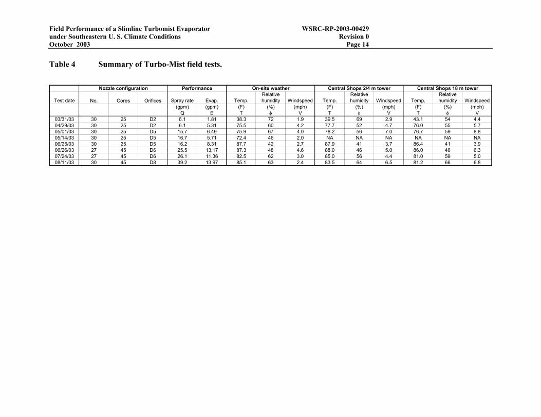
Readings from the Clear gauge are preferred over the Yellow gauge because the precision of the Clear gauge is 0.01” compared to 0.1” for the Yellow gauge. Figure 11 shows a cross-plot of data from absorbent pads and Yellow gauges across all tests. The plot suggests 0.25” as the optimal cut-off value in retrospect.
For each test a map of spray fallback was created by interpolating the point data from the preferred collection device at each grid location onto a regular 20’ by 20’ grid using a kriging algorithm embedded in Tecplot (Amtec Engineering, Inc.). Numerical integration of the kriged surface produced the total amount of spray fallback for a given test. The fallback rate was computed by dividing the fallback amount by the duration of the test. Detailed calculations for each test are provided in a Controlled Laboratory Notebook (WSRC-NB-2001-00167) and the Appendices.
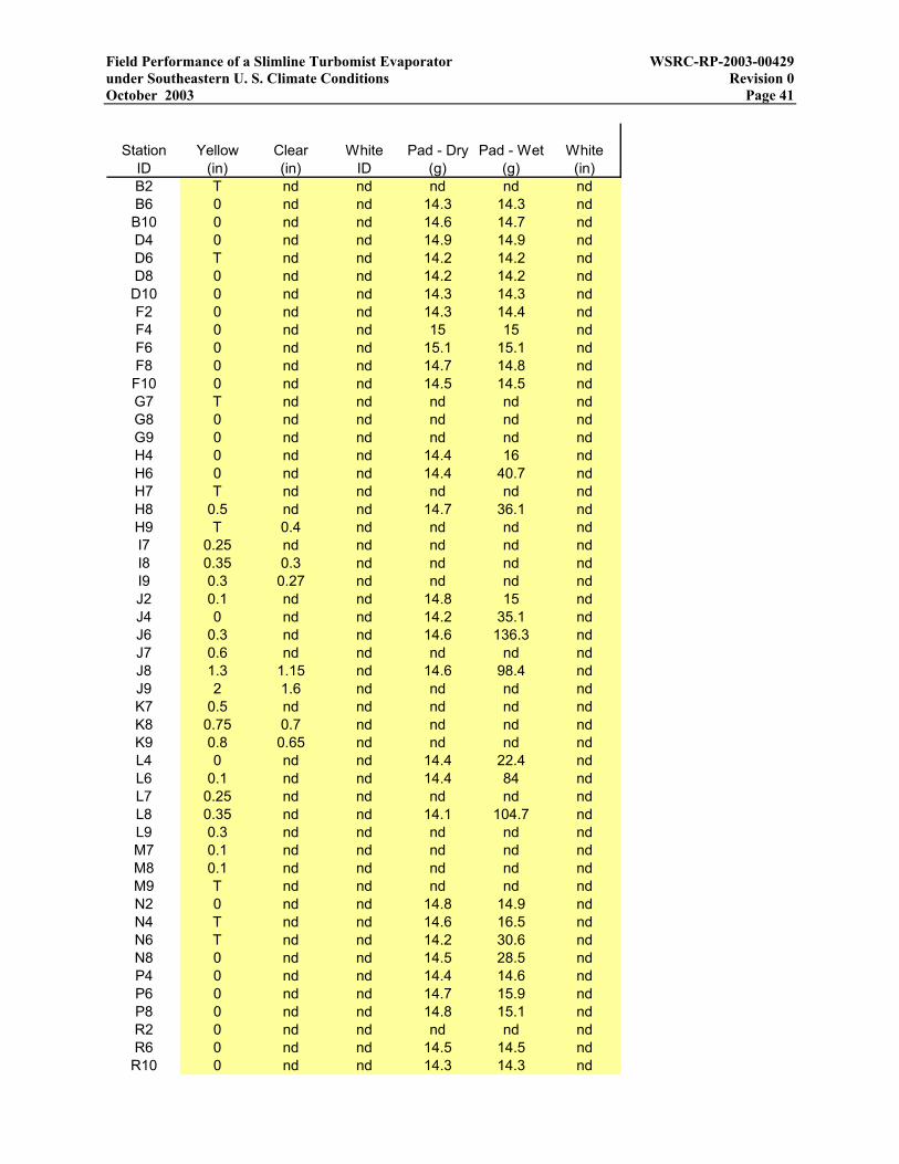
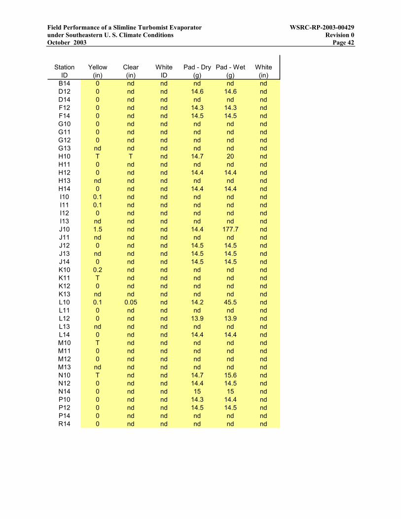
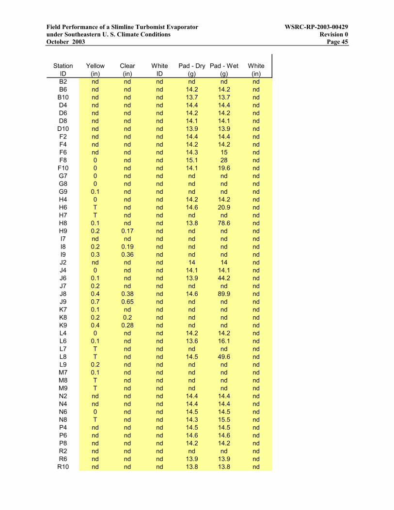
Table 4 summarizes the evaporator configuration, average weather conditions, and spray fallback for each field test. Because testing was conducted from March through August, periods of rainfall were avoided, and daytime testing was preferred for logistical reasons, most tests were
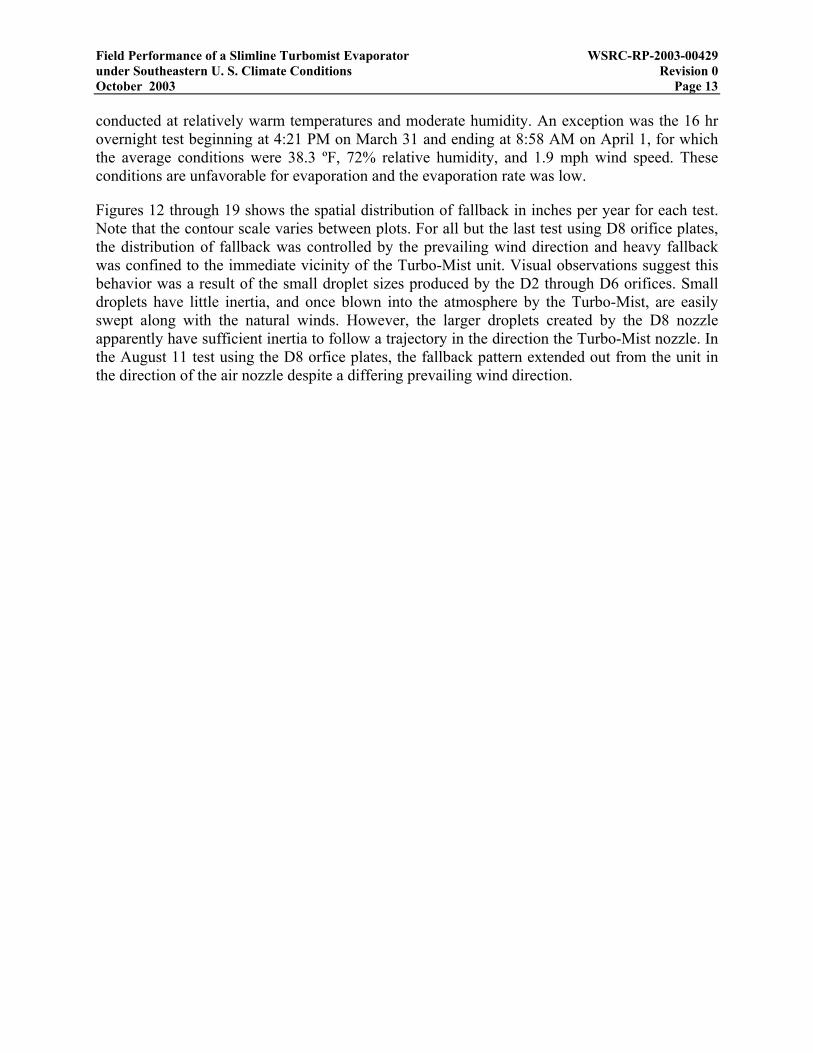
Field Performance of a Slimline Turbomist Evaporator WSRC-RP-2003-00429 under Southeastern U. S. Climate Conditions Revision 0 October 2003 Page 13 conducted at relatively warm temperatures and moderate humidity. An exception was the 16 hr overnight test beginning at 4:21 PM on March 31 and ending at 8:58 AM on April 1, for which the average conditions were 38.3 ºF, 72% relative humidity, and 1.9 mph wind speed. These conditions are unfavorable for evaporation and the evaporation rate was low.
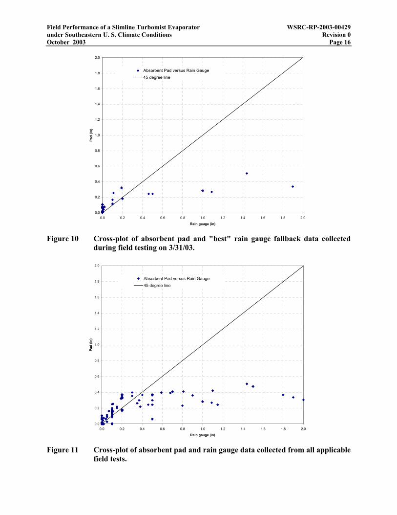
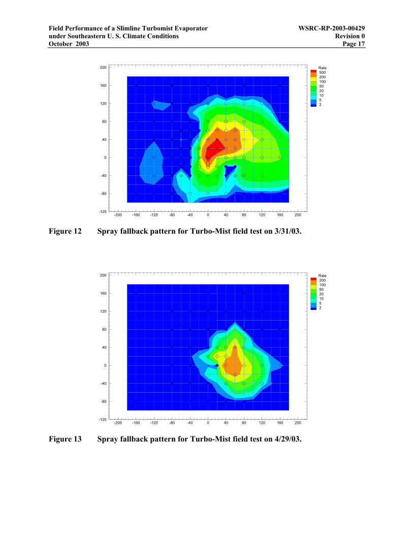
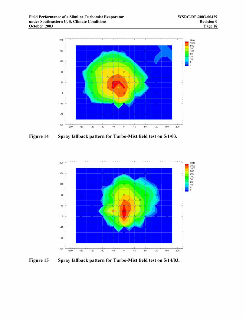
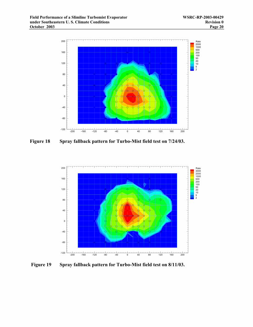
Figures 12 through 19 shows the spatial distribution of fallback in inches per year for each test. Note that the contour scale varies between plots. For all but the last test using D8 orifice plates, the distribution of fallback was controlled by the prevailing wind direction and heavy fallback was confined to the immediate vicinity of the Turbo-Mist unit. Visual observations suggest this behavior was a result of the small droplet sizes produced by the D2 through D6 orifices. Small droplets have little inertia, and once blown into the atmosphere by the Turbo-Mist, are easily swept along with the natural winds. However, the larger droplets created by the D8 nozzle apparently have sufficient inertia to follow a trajectory in the direction the Turbo-Mist nozzle. In the August 11 test using the D8 orfice plates, the fallback pattern extended out from the unit in the direction of the air nozzle despite a differing prevailing wind direction.
Field Performance of a Slimline Turbomist Evaporator WSRC-RP-2003-00429 under Southeastern U. S. Climate Conditions Revision 0 October 2003 Page 14
Table 4 Summary of Turbo-Mist field tests.
Test date No. Cores Orifices Spray rate Evap. Temp.Relative humidity Windspeed Temp.
Relative humidity Windspeed Temp.
Relative humidity Windspeed
(gpm) (gpm) (F) (%) (mph) (F) (%) (mph) (F) (%) (mph)Q E T φ V T φ V T φ V
03/31/03 30 25 D2 6.1 1.81 38.3 72 1.9 39.5 69 2.9 43.1 54 4.404/29/03 30 25 D2 6.1 5.31 75.5 60 4.2 77.7 52 4.7 76.0 55 5.705/01/03 30 25 D5 15.7 6.49 75.9 67 4.0 78.2 56 7.0 76.7 59 8.805/14/03 30 25 D5 16.7 5.71 72.4 46 2.0 NA NA NA NA NA NA06/25/03 30 25 D5 16.2 8.31 87.7 42 2.7 87.9 41 3.7 86.4 41 3.906/26/03 27 45 D6 25.5 13.17 87.3 48 4.6 88.0 46 5.0 86.0 46 6.307/24/03 27 45 D6 26.1 11.36 82.5 62 3.0 85.0 56 4.4 81.0 59 5.008/11/03 30 45 D8 39.2 13.97 85.1 63 2.4 83.5 64 6.5 81.2 66 6.8
Central Shops 18 m towerCentral Shops 2/4 m towerOn-site weatherPerformanceNozzle configuration

Field Performance of a Slimline Turbomist Evaporator WSRC-RP-2003-00429 under Southeastern U. S. Climate Conditions Revision 0 October 2003 Page 15
0.0
0.2
0.4
0.6
0.8
1.0
1.2
0.0 0.2 0.4 0.6 0.8 1.0 1.2
Yellow gauge (in)
Cle
ar g
auge
(in)
Clear versus Yellow Gauge45 degree line
Figure 8 Cross-plot of Clear and Yellow rain gauge data collected during field testing on 3/31/03.
0.0
0.2
0.4
0.6
0.8
1.0
1.2
0.0 0.2 0.4 0.6 0.8 1.0 1.2
Yellow gauge (in)
Whi
te g
auge
(in)
White versus Yellow Gauge45 degree line
Figure 9 Cross-plot of White and Yellow rain gauge data collected during field testing on 3/31/03.
Field Performance of a Slimline Turbomist Evaporator WSRC-RP-2003-00429 under Southeastern U. S. Climate Conditions Revision 0 October 2003 Page 16
0.0
0.2
0.4
0.6
0.8
1.0
1.2
1.4
1.6
1.8
2.0
0.0 0.2 0.4 0.6 0.8 1.0 1.2 1.4 1.6 1.8 2.0
Rain gauge (in)
Pad
(in)
Absorbent Pad versus Rain Gauge45 degree line
Figure 10 Cross-plot of absorbent pad and "best" rain gauge fallback data collected during field testing on 3/31/03.
0.0
0.2
0.4
0.6
0.8
1.0
1.2
1.4
1.6
1.8
2.0
0.0 0.2 0.4 0.6 0.8 1.0 1.2 1.4 1.6 1.8 2.0
Rain gauge (in)
Pad
(in)
Absorbent Pad versus Rain Gauge45 degree line
Figure 11 Cross-plot of absorbent pad and rain gauge data collected from all applicable field tests.
Field Performance of a Slimline Turbomist Evaporator WSRC-RP-2003-00429 under Southeastern U. S. Climate Conditions Revision 0 October 2003 Page 17
-200 -160 -120 -80 -40 0 40 80 120 160 200-120
-80
-40
0
40
80
120
160
200 Rate50020010050201052
Figure 12 Spray fallback pattern for Turbo-Mist field test on 3/31/03.
-200 -160 -120 -80 -40 0 40 80 120 160 200-120
-80
-40
0
40
80
120
160
200 Rate20010050201052
Figure 13 Spray fallback pattern for Turbo-Mist field test on 4/29/03.
Field Performance of a Slimline Turbomist Evaporator WSRC-RP-2003-00429 under Southeastern U. S. Climate Conditions Revision 0 October 2003 Page 18
-200 -160 -120 -80 -40 0 40 80 120 160 200-120
-80
-40
0
40
80
120
160
200 Rate100050020010050201052
Figure 14 Spray fallback pattern for Turbo-Mist field test on 5/1/03.
-200 -160 -120 -80 -40 0 40 80 120 160 200-120
-80
-40
0
40
80
120
160
200 Rate2000100050020010050201052
Figure 15 Spray fallback pattern for Turbo-Mist field test on 5/14/03.

Field Performance of a Slimline Turbomist Evaporator WSRC-RP-2003-00429 under Southeastern U. S. Climate Conditions Revision 0 October 2003 Page 19
-200 -160 -120 -80 -40 0 40 80 120 160 200-120
-80
-40
0
40
80
120
160
200 Rate1500100050020010050201052
Figure 16 Spray fallback pattern for Turbo-Mist field test on 6/25/03.
-200 -160 -120 -80 -40 0 40 80 120 160 200-120
-80
-40
0
40
80
120
160
200 Rate20001500100050020010050201052
Figure 17 Spray fallback pattern for Turbo-Mist field test on 6/26/03.
Field Performance of a Slimline Turbomist Evaporator WSRC-RP-2003-00429 under Southeastern U. S. Climate Conditions Revision 0 October 2003 Page 20
-200 -160 -120 -80 -40 0 40 80 120 160 200-120
-80
-40
0
40
80
120
160
200 Rate2000100050020010050201052
Figure 18 Spray fallback pattern for Turbo-Mist field test on 7/24/03.
-200 -160 -120 -80 -40 0 40 80 120 160 200-120
-80
-40
0
40
80
120
160
200 Rate30002000100050020010050201052
Figure 19 Spray fallback pattern for Turbo-Mist field test on 8/11/03.
Field Performance of a Slimline Turbomist Evaporator WSRC-RP-2003-00429 under Southeastern U. S. Climate Conditions Revision 0 October 2003 Page 21
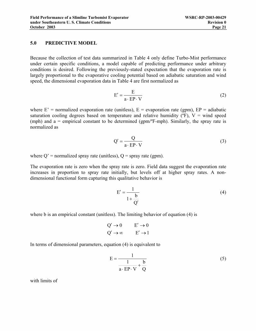
5.0 PREDICTIVE MODEL
Because the collection of test data summarized in Table 4 only define Turbo-Mist performance under certain specific conditions, a model capable of predicting performance under arbitrary conditions is desired. Following the previously-stated expectation that the evaporation rate is largely proportional to the evaporative cooling potential based on adiabatic saturation and wind speed, the dimensional evaporation data in Table 4 are first normalized as
VEPa
EE⋅⋅
=′ (2)
where E’ = normalized evaporation rate (unitless), E = evaporation rate (gpm), EP = adiabatic saturation cooling degrees based on temperature and relative humidity (ºF), V = wind speed (mph) and a = empirical constant to be determined (gpm/ºF-mph). Similarly, the spray rate is normalized as
VEPa
QQ⋅⋅
=′ (3)
where Q’ = normalized spray rate (unitless), Q = spray rate (gpm).
The evaporation rate is zero when the spray rate is zero. Field data suggest the evaporation rate increases in proportion to spray rate initially, but levels off at higher spray rates. A non-dimensional functional form capturing this qualitative behavior is
Qb1
1E
′+
=′ (4)
where b is an empirical constant (unitless). The limiting behavior of equation (4) is
1E Q0E 0Q
→′∞→′→′→′
In terms of dimensional parameters, equation (4) is equivalent to
Qb
VEPa1
1E+
⋅⋅
= (5)
with limits of

Field Performance of a Slimline Turbomist Evaporator WSRC-RP-2003-00429 under Southeastern U. S. Climate Conditions Revision 0 October 2003 Page 22
VEPaE Q
0E 0Q⋅⋅→∞→
→→
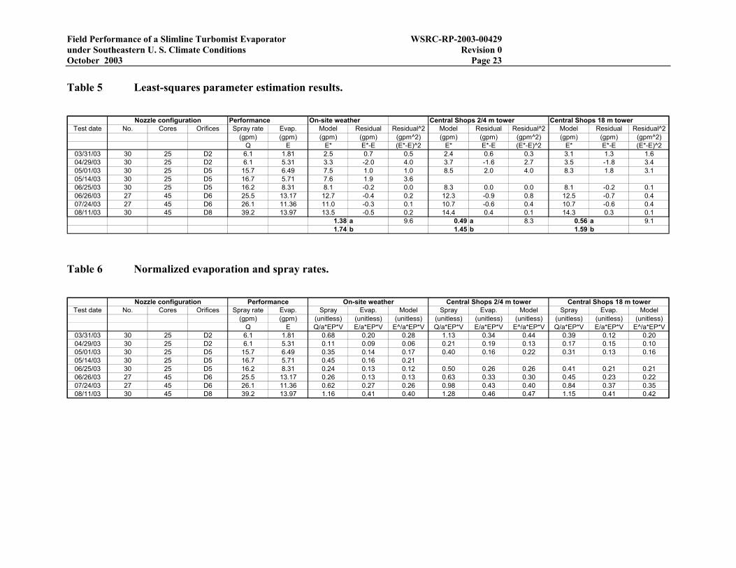
For each set of weather parameters, optimal values for the empirical constants a and b were determined using least-squares parameter fitting, as shown in Table 5. For these settings, the normalized evaporation and spray rates are listed in Table 6.
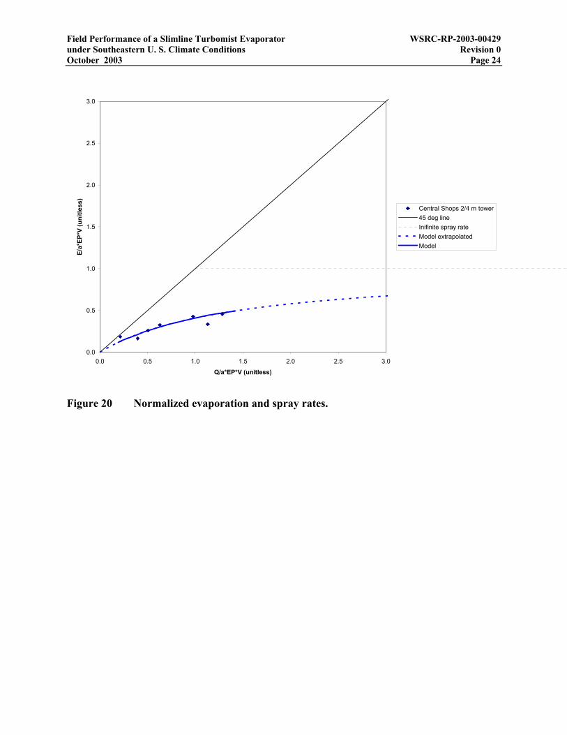
Normalized evaporation rate is plotted against normalized spray rate in Figure 20 based on weather data from the Central Shops 2/4 meter towers. Also shown in the figure is the predictive model defined by equation (4) and parameters in Table 5. The model fits the data reasonably well.
Field Performance of a Slimline Turbomist Evaporator WSRC-RP-2003-00429 under Southeastern U. S. Climate Conditions Revision 0 October 2003 Page 23
Table 5 Least-squares parameter estimation results.
Nozzle configuration Performance On-site weather Central Shops 2/4 m tower Central Shops 18 m towerTest date No. Cores Orifices Spray rate Evap. Model Residual Residual^2 Model Residual Residual^2 Model Residual Residual^2
(gpm) (gpm) (gpm) (gpm) (gpm^2) (gpm) (gpm) (gpm^2) (gpm) (gpm) (gpm^2)Q E E* E*-E (E*-E)^2 E* E*-E (E*-E)^2 E* E*-E (E*-E)^2
03/31/03 30 25 D2 6.1 1.81 2.5 0.7 0.5 2.4 0.6 0.3 3.1 1.3 1.604/29/03 30 25 D2 6.1 5.31 3.3 -2.0 4.0 3.7 -1.6 2.7 3.5 -1.8 3.405/01/03 30 25 D5 15.7 6.49 7.5 1.0 1.0 8.5 2.0 4.0 8.3 1.8 3.105/14/03 30 25 D5 16.7 5.71 7.6 1.9 3.606/25/03 30 25 D5 16.2 8.31 8.1 -0.2 0.0 8.3 0.0 0.0 8.1 -0.2 0.106/26/03 27 45 D6 25.5 13.17 12.7 -0.4 0.2 12.3 -0.9 0.8 12.5 -0.7 0.407/24/03 27 45 D6 26.1 11.36 11.0 -0.3 0.1 10.7 -0.6 0.4 10.7 -0.6 0.408/11/03 30 45 D8 39.2 13.97 13.5 -0.5 0.2 14.4 0.4 0.1 14.3 0.3 0.1
1.38 a 9.6 0.49 a 8.3 0.56 a 9.11.74 b 1.45 b 1.59 b
Table 6 Normalized evaporation and spray rates.
Test date No. Cores Orifices Spray rate Evap. Spray Evap. Model Spray Evap. Model Spray Evap. Model(gpm) (gpm) (unitless) (unitless) (unitless) (unitless) (unitless) (unitless) (unitless) (unitless) (unitless)
Q E Q/a*EP*V E/a*EP*V E^/a*EP*V Q/a*EP*V E/a*EP*V E^/a*EP*V Q/a*EP*V E/a*EP*V E^/a*EP*V03/31/03 30 25 D2 6.1 1.81 0.68 0.20 0.28 1.13 0.34 0.44 0.39 0.12 0.2004/29/03 30 25 D2 6.1 5.31 0.11 0.09 0.06 0.21 0.19 0.13 0.17 0.15 0.1005/01/03 30 25 D5 15.7 6.49 0.35 0.14 0.17 0.40 0.16 0.22 0.31 0.13 0.1605/14/03 30 25 D5 16.7 5.71 0.45 0.16 0.2106/25/03 30 25 D5 16.2 8.31 0.24 0.13 0.12 0.50 0.26 0.26 0.41 0.21 0.2106/26/03 27 45 D6 25.5 13.17 0.26 0.13 0.13 0.63 0.33 0.30 0.45 0.23 0.2207/24/03 27 45 D6 26.1 11.36 0.62 0.27 0.26 0.98 0.43 0.40 0.84 0.37 0.3508/11/03 30 45 D8 39.2 13.97 1.16 0.41 0.40 1.28 0.46 0.47 1.15 0.41 0.42
Nozzle configuration Central Shops 18 m towerCentral Shops 2/4 m towerOn-site weatherPerformance
Field Performance of a Slimline Turbomist Evaporator WSRC-RP-2003-00429 under Southeastern U. S. Climate Conditions Revision 0 October 2003 Page 24
0.0
0.5
1.0
1.5
2.0
2.5
3.0
0.0 0.5 1.0 1.5 2.0 2.5 3.0
Q/a*EP*V (unitless)
E/a*
EP*V
(uni
tless
)
Central Shops 2/4 m tower45 deg lineInifinite spray rateModel extrapolatedModel
Figure 20 Normalized evaporation and spray rates.
Field Performance of a Slimline Turbomist Evaporator WSRC-RP-2003-00429 under Southeastern U. S. Climate Conditions Revision 0 October 2003 Page 25
6.0 FORECAST EVAPORATION RATES
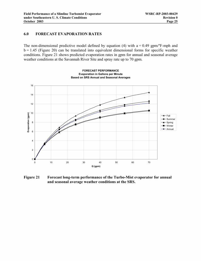
The non-dimensional predictive model defined by equation (4) with a = 0.49 gpm/ºF-mph and b = 1.45 (Figure 20) can be translated into equivalent dimensional forms for specific weather conditions. Figure 21 shows predicted evaporation rates in gpm for annual and seasonal average weather conditions at the Savannah River Site and spray rate up to 70 gpm.
FORECAST PERFORMANCEEvaporation in Gallons per Minute
Based on SRS Annual and Seasonal Averages
0
2
4
6
8
10
12
14
16
0 10 20 30 40 50 60 70
Q (gpm)
Evap
orat
ion
(gpm
)
FallSummerSpringWinterAnnual
Figure 21 Forecast long-term performance of the Turbo-Mist evaporator for annual and seasonal average weather conditions at the SRS.
Field Performance of a Slimline Turbomist Evaporator WSRC-RP-2003-00429 under Southeastern U. S. Climate Conditions Revision 0 October 2003 Page 26
7.0 SUMMARY AND CONCLUSIONS
The evaporation rate of spray from a Slimline Turbo-Mist evaporator is approximately proportional to the evaporative cooling potential of "dry" air based on temperature and humidity, and wind speed. As a secondary effort, the evaporation rate was also observed to increase with spray rate, to a point of diminishing increases. A model has been developed for predicting evaporation rate as a function of weather conditions and spray rate. Forecast performance of the Turbo-Mist evaporator under average temperature, humidity and wind speed conditions for the year and each season are plotted in Figure 21 as a function of spray rate (controlled by nozzle orifice selection). The fallback rate is the spray rate less the evaporation rate. If significant fallback is tolerable, an evaporation rate averaging about 12 gpm is estimated for operation at the SRS on a year-round basis.
8.0 REFERENCES
American Society of Heating, Refrigerating and Air-Conditioning Engineers, 1985, ASHRAE Handbook; 1985 Fundamentals, American Society of Heating, Refrigerating and Air-Conditioning Engineers, Inc., Atlanta GA.
Controlled Laboratory Notebook WSRC-NB-2001-00167, assigned to G. P. Flach.
Hunter, C. H. and C. P. Tatum, 1997, Meteorological annual report for 1996 (U), WSRC-TR-97-0214.
Reynolds, W. C. and H. C. Perkins, 1977, Engineering Thermodynamics, McGraw-Hill, New York, 690 p.
Flach, G. P., 2002, Evaluation of Evaporation Technologies for Treating Contaminated Groundwater (U), WSRC-TR-2002-00432.

Field Performance of a Slimline Turbomist Evaporator WSRC-RP-2003-00429 under Southeastern U. S. Climate Conditions Revision 0 October 2003 Page 27
Appendix A – Data and analysis for Turbo-Mist field test on 3/31/03
30 No. 25 cores with D2 orifice plates March 31 - April 1, 200330 Number of spray nozzles 0.001897 yr Duration of test25 Cores 0.6924 dayD2 Orifices 16.62 hr
3/31/03 16:21 37711.6813 Start of test 997 min6621 gal m3 Nozzle flow totalizer 59820 sec
5.1 gal/min m3/hr Nozzle flowrate - indicated 6036.5 gal 22.9 m3 Spray volume45120 gal m3 Bypass flow totalizer 114530 gal 433.5 m3 Bypass volume116.1 gal/min m3/hr Bypass flowrate - indicated
104 psi Pa P1 6.1 gal/min 1.38 m3/hr Spray flowrate98 psi Pa P2 115 gal/min 26.1 m3/hr Bypass flowrate
100 psi Pa P3 21 in2 0.0135 m2 Pad area4/1/03 0:11 37712.0076 Midpoint 0.1458 ft2
9483.1 gal m3 Nozzle flow totalizer 3.35E-06 acre5.8 gal/min m3/hr Nozzle flowrate - indicated 480 volts Voltage
99300 gal m3 Bypass flow totalizer 36 amps Current114.2 gal/min m3/hr Bypass flowrate - indicated 29.9 kW Power
100 psi Pa P1 38.3 F 3.49 C Temperature99 psi Pa P2 72% 72% Relative humidity
100 psi Pa P3 1.9 mph 0.84 m/s Wind speed4/1/03 8:58 37712.3736 End of test 226.27 deg 226.27 deg Wind direction
12657.5 gal m3 Nozzle flow totalizer 6.05 gpm Spray6.1 gal/min m3/hr Nozzle flowrate - indicated 4.24 gpm Fallback
159650 gal m3 Bypass flow totalizer 1.81 gpm Evaporation116.1 gal/min m3/hr Bypass flowrate - indicated 30%
102 psi Pa P1 29.9 kW Power98 psi Pa P2 0.08 $/kW-hr Energy cost
100 psi Pa P3 0.022 $/gal Cost3 in Pad width 0.056 $/gal Direct heating cost7 in Pad length 39% Relative cost
Field Performance of a Slimline Turbomist Evaporator WSRC-RP-2003-00429 under Southeastern U. S. Climate Conditions Revision 0 October 2003 Page 28 Adiabatic saturation / swamp cooler calculation using ASHRAE (1985) equationsConstants source
univ. gas const. R 1545.33 ft-lbf/(lbmole-R)molecular wt. air Ma 28.9645 lbm/lbmole from eqn (24)air gas constant Ra 53.35 ft-lbf/(lbm-R)
Incoming air streampressure p 14.7 psia
temperature t 38.282 F 3.5 C 497.952 R 31Mar03 - 01Apr03 Field Testrelative humidity φ 0.72 unitless
sat. pressure pws 0.1152 psia eqn (4)water vap. pres. pw 0.0829 psia eqn (22)
humidity ratio W, γ 0.003528 unitless 24.69 grains/lbma eqn (20)sat. humidity ratio Ws 0.004913 unitless eqn (21)deg. of saturation µ 0.7180 unitless eqn (10)
specific volume ν 12.62 ft3/lbma eqn (26)12.58 ft3/lbm using (1+γ) factor and eqn (26)12.55 ft3/lbm using ideal gas law
specific enthalpy h 12.99 BTU/lbma eqn (30)Outgoing for adiabatic saturation/evaporation
pressure p 14.7 psiatemperature t 34.88 F 1.6 C 494.55 R
relative humidity φ 1.00 unitlesssat. pressure pws 0.1007 psia eqn (4)
water vap. pres. pw 0.1007 psia eqn (22)humidity ratio W, γ 0.004291 lbmw/lbma 30.03 grains/lbma eqn (20)
sat. humidity ratio Ws 0.004291 unitless eqn (21)deg. of saturation µ 1.0000 unitless eqn (10)
specific volume ν 12.55 ft3/lbma eqn (26)12.50 ft3/lbm using (1+γ) factor and eqn (26)12.46 ft3/lbm using ideal gas law
specific enthalpy h 12.99 BTU/lbma eqn (30)Differences
temperature ∆t -3.4 Frelative humidity ∆φ 0.28 unitless
enthalpy ∆h 0.00 BTU/lbma
humidity ratio ∆W, ∆γ 0.000763 lbmw/lbma 5.34 grains/lbma
Evaporation system parametersWind speed v 1.9 mi/hr 2.76 ft/s
Height h 35.0 ftWidth w 35.0 ft
Xsec area Α 1225 ft2
Incoming wet air vol. flow Q 3376 ft3/s 2.0E+05 ft3/min (cfm)
Dry air mass flow ma 267 lbma/sEvaporation rate me 0.20 lbmw/s 12.25 lbmw/min
Liq. water density ρ 62.3 lbm/ft3 @ 70FEvaporation rate Qe 0.003 ft3/s 1.47 gal/min 88 gal/hr

Field Performance of a Slimline Turbomist Evaporator WSRC-RP-2003-00429 under Southeastern U. S. Climate Conditions Revision 0 October 2003 Page 29
Station Yellow Clear White Pad - Dry Pad - Wet WhiteID (in) (in) ID (g) (g) (in)B2 0 nd nd nd nd ndB6 0 nd nd nd nd ndB10 0 nd nd nd nd ndD4 0 nd nd 14.3 15.8 ndD6 0 nd nd 14.3 15.2 ndD8 0 nd nd 14.5 15.7 ndD10 0 nd nd 14.4 17.3 ndF2 0 nd nd nd nd ndF4 0 nd nd 14.0 15.3 ndF6 0 nd nd 14.6 15.7 ndF8 0 nd nd nd nd ndF10 0 nd nd nd nd ndG7 0 nd nd nd nd ndG8 0 nd nd 14.3 15.7 ndG9 T nd nd nd nd ndH4 0 nd nd 14.4 15.4 ndH6 0 nd nd 14.3 15.2 ndH7 0 nd nd nd nd ndH8 0 T TM-2 nd nd 0.02H9 T nd nd nd nd ndI7 0 nd nd nd nd ndI8 0 nd nd 14.8 19.4 ndI9 T nd nd 14.4 34.5 ndJ2 0 nd nd nd nd ndJ4 0 nd nd 14.3 16.9 ndJ6 T nd nd 14.7 41.7 ndJ7 0.1 nd nd nd nd ndJ8 0.45 0.46 TM-4 14.9 98.9 0.39J9 1.3 1.09 TM-5 14.8 107.5 1.06K7 0.5 nd nd nd nd ndK8 1.0 nd nd 14.3 112.0 ndK9 1.9 nd nd 14.4 130.6 ndL4 0 nd nd 14.4 20.3 ndL6 0.1 nd nd 14.9 72.4 ndL7 0.3 nd nd nd nd ndL8 0.9 0.76 TM-7 nd nd 0.53L9 0.9 nd nd nd nd ndM7 0.5 nd nd nd nd ndM8 0.5 nd nd 14.0 97.8 ndM9 0.6 nd nd nd nd ndN2 0 nd nd nd nd ndN4 0 nd nd 13.8 18.3 ndN6 0.1 nd nd 14.3 53.7 ndN8 0.3 nd nd nd nd ndP4 0 nd nd 14.8 18.2 ndP6 T nd nd 14.3 36.2 ndP8 0.2 nd nd 14.4 77.1 ndR2 0 nd nd nd nd ndR6 0 nd nd nd nd ndR10 0.1 nd nd nd nd nd
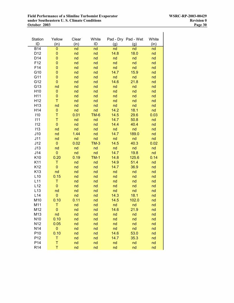
Field Performance of a Slimline Turbomist Evaporator WSRC-RP-2003-00429 under Southeastern U. S. Climate Conditions Revision 0 October 2003 Page 30
Station Yellow Clear White Pad - Dry Pad - Wet WhiteID (in) (in) ID (g) (g) (in)
B14 0 nd nd nd nd ndD12 0 nd nd 14.8 18.0 ndD14 0 nd nd nd nd ndF12 0 nd nd nd nd ndF14 0 nd nd nd nd ndG10 0 nd nd 14.7 15.9 ndG11 0 nd nd nd nd ndG12 0 nd nd 14.6 21.8 ndG13 nd nd nd nd nd ndH10 0 nd nd nd nd ndH11 0 nd nd nd nd ndH12 T nd nd nd nd ndH13 nd nd nd nd nd ndH14 0 nd nd 14.2 18.1 ndI10 T 0.01 TM-6 14.5 29.6 0.03I11 T nd nd 14.7 50.8 ndI12 0 nd nd 14.4 40.4 ndI13 nd nd nd nd nd ndJ10 nd 1.44 nd 14.7 189.0 ndJ11 nd nd nd nd nd ndJ12 0 0.02 TM-3 14.5 40.3 0.02J13 nd nd nd nd nd ndJ14 0 nd nd 14.7 19.8 ndK10 0.20 0.19 TM-1 14.8 125.6 0.14K11 T nd nd 14.9 51.4 ndK12 0 nd nd 14.7 36.9 ndK13 nd nd nd nd nd ndL10 0.15 nd nd nd nd ndL11 T nd nd nd nd ndL12 0 nd nd nd nd ndL13 nd nd nd nd nd ndL14 0 nd nd 14.3 18.1 ndM10 0.10 0.11 nd 14.5 102.0 ndM11 T nd nd nd nd ndM12 0 nd nd 14.6 21.9 ndM13 nd nd nd nd nd ndN10 0.10 nd nd nd nd ndN12 0.05 nd nd nd nd ndN14 0 nd nd nd nd ndP10 0.10 nd nd 14.6 53.0 ndP12 T nd nd 14.7 35.3 ndP14 T nd nd nd nd ndR14 T nd nd nd nd nd

Field Performance of a Slimline Turbomist Evaporator WSRC-RP-2003-00429 under Southeastern U. S. Climate Conditions Revision 0 October 2003 Page 31
Appendix B – Data and analysis for Turbo-Mist field test on 4/29/03
30 No. 25 cores with D2 orifice plates April 29, 200330 Number of spray nozzles 0.000812 yr Duration of test25 Cores 0.2965 dayD2 Orifices 7.12 hr
4/29/03 8:16 37740.3444 Start of test 427 min12681.2 gal m3 T1-Nozzle flow totalizer 25620 sec
5.8 gal/min m3/hr Nozzle flowrate - indicated 2614.8 gal 9.9 m3 Spray volume160030 gal m3 T2-Bypass flow totalizer 47830 gal 181.1 m3 Bypass volume
115 gal/min m3/hr Bypass flowrate - indicated106 psi Pa P1 6.1 gal/min 1.39 m3/hr Spray flowrate100 psi Pa P2 112 gal/min 25.4 m3/hr Bypass flowrate102 psi Pa P3 21 in2 0.0135 m2 Pad area
4/29/03 11:41 37740.4868 Midpoint 0.1458 ft2
13934.8 gal m3 Nozzle flow totalizer 3.35E-06 acre6.5 gal/min m3/hr Nozzle flowrate - indicated volts Voltage
183000 gal m3 Bypass flow totalizer amps Current114.1 gal/min m3/hr Bypass flowrate - indicated 0.0 kW Power
102 psi Pa P1 75.5 F 24.19 C Temperature98 psi Pa P2 60% 60% Relative humidity
100 psi Pa P3 4.2 mph 1.86 m/s Wind speed4/29/03 15:23 37740.641 End of test 209.056667 deg 209.06 deg Wind direction
15296 gal m3 Nozzle flow totalizer 6.12 gpm Spray6.5 gal/min m3/hr Nozzle flowrate - indicated 0.81 gpm Fallback
207860 gal m3 Bypass flow totalizer 5.31 gpm Evaporation114.6 gal/min m3/hr Bypass flowrate - indicated 87%
102 psi Pa P1 0.0 kW Power98 psi Pa P2 0.08 $/kW-hr Energy cost
100 psi Pa P3 0.000 $/gal Cost3 in Pad width 0.056 $/gal Direct heating cost7 in Pad length 0% Relative cost

Field Performance of a Slimline Turbomist Evaporator WSRC-RP-2003-00429 under Southeastern U. S. Climate Conditions Revision 0 October 2003 Page 32 Adiabatic saturation / swamp cooler calculation using ASHRAE (1985) equationsConstants source
univ. gas const. R 1545.33 ft-lbf/(lbmole-R)molecular wt. air Ma 28.9645 lbm/lbmole from eqn (24)air gas constant Ra 53.35 ft-lbf/(lbm-R)
Incoming air streampressure p 14.7 psia
temperature t 75.542 F 24.2 C 535.212 R 29Apr03 Field Testrelative humidity φ 0.60 unitless
sat. pressure pws 0.4437 psia eqn (4)water vap. pres. pw 0.2653 psia eqn (22)
humidity ratio W, γ 0.011430 unitless 80.01 grains/lbma eqn (20)sat. humidity ratio Ws 0.019359 unitless eqn (21)deg. of saturation µ 0.5904 unitless eqn (10)
specific volume ν 13.74 ft3/lbma eqn (26)13.58 ft3/lbm using (1+γ) factor and eqn (26)13.49 ft3/lbm using ideal gas law
specific enthalpy h 30.64 BTU/lbma eqn (30)Outgoing for adiabatic saturation/evaporation
pressure p 14.7 psiatemperature t 65.59 F 18.7 C 525.26 R
relative humidity φ 1.00 unitlesssat. pressure pws 0.3161 psia eqn (4)
water vap. pres. pw 0.3161 psia eqn (22)humidity ratio W, γ 0.013668 lbmw/lbma 95.68 grains/lbma eqn (20)
sat. humidity ratio Ws 0.013668 unitless eqn (21)deg. of saturation µ 1.0000 unitless eqn (10)
specific volume ν 13.53 ft3/lbma eqn (26)13.35 ft3/lbm using (1+γ) factor and eqn (26)13.24 ft3/lbm using ideal gas law
specific enthalpy h 30.64 BTU/lbma eqn (30)Differences
temperature ∆t -10.0 Frelative humidity ∆φ 0.40 unitless
enthalpy ∆h 0.00 BTU/lbma
humidity ratio ∆W, ∆γ 0.002238 lbmw/lbma 15.67 grains/lbma
Evaporation system parametersWind speed v 4.2 mi/hr 6.12 ft/s
Height h 35.0 ftWidth w 35.0 ft
Xsec area Α 1225 ft2
Incoming wet air vol. flow Q 7493 ft3/s 4.5E+05 ft3/min (cfm)
Dry air mass flow ma 545 lbma/sEvaporation rate me 1.22 lbmw/s 73.24 lbmw/min
Liq. water density ρ 62.3 lbm/ft3 @ 70FEvaporation rate Qe 0.020 ft3/s 8.79 gal/min 528 gal/hr
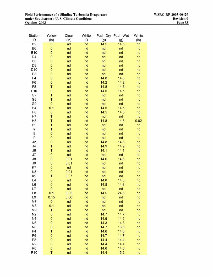
Field Performance of a Slimline Turbomist Evaporator WSRC-RP-2003-00429 under Southeastern U. S. Climate Conditions Revision 0 October 2003 Page 33
Station Yellow Clear White Pad - Dry Pad - Wet WhiteID (in) (in) ID (g) (g) (in)B2 0 nd nd 14.5 14.5 ndB6 0 nd nd nd nd ndB10 0 nd nd nd nd ndD4 0 nd nd nd nd ndD6 0 nd nd nd nd ndD8 0 nd nd nd nd ndD10 0 nd nd nd nd ndF2 0 nd nd nd nd ndF4 0 nd nd 14.8 14.8 ndF6 0 nd nd 14.2 14.2 ndF8 T nd nd 14.8 14.8 ndF10 0 nd nd 14.5 14.5 ndG7 T nd nd nd nd ndG8 T nd nd nd nd ndG9 0 nd nd nd nd ndH4 0.1 nd nd 14.5 14.5 ndH6 0 nd nd 14.5 14.5 ndH7 T nd nd nd nd ndH8 T nd nd 14.8 14.8 0.02H9 T nd nd nd nd ndI7 T nd nd nd nd ndI8 0 nd nd nd nd ndI9 0 nd nd nd nd ndJ2 0 nd nd 14.8 14.8 ndJ4 T nd nd 14.9 14.9 ndJ6 T nd nd 14.1 14.1 ndJ7 0 nd nd nd nd ndJ8 0 0.01 nd 14.6 14.6 ndJ9 0 0.01 nd nd nd ndK7 0 nd nd nd nd ndK8 0 0.01 nd nd nd ndK9 T 0.07 nd nd nd ndL4 0 nd nd 14.8 14.8 ndL6 0 nd nd 14.8 14.8 ndL7 0 nd nd nd nd ndL8 0.1 0.05 nd 14.5 24.5 ndL9 0.15 0.06 nd nd nd ndM7 0 nd nd nd nd ndM8 0.1 nd nd nd nd ndM9 T nd nd nd nd ndN2 0 nd nd 14.7 14.7 ndN4 0 nd nd 14.5 14.5 ndN6 0 nd nd 14.3 14.3 ndN8 0 nd nd 14.7 16.6 ndP4 T nd nd 14.6 14.6 ndP6 0 nd nd 14.7 14.7 ndP8 0 nd nd 14.4 14.4 ndR2 0 nd nd 14.4 14.4 ndR6 0 nd nd 14.6 14.6 ndR10 T nd nd 14.4 15.2 nd

Field Performance of a Slimline Turbomist Evaporator WSRC-RP-2003-00429 under Southeastern U. S. Climate Conditions Revision 0 October 2003 Page 34
Station Yellow Clear White Pad - Dry Pad - Wet WhiteID (in) (in) ID (g) (g) (in)
B14 0 nd nd 14.5 14.5 ndD12 0 nd nd nd nd ndD14 0 nd nd nd nd ndF12 0 nd nd 14 14 ndF14 0 nd nd nd nd ndG10 0 nd nd nd nd ndG11 0 nd nd nd nd ndG12 0 nd nd nd nd ndG13 0 nd nd nd nd ndH10 0 nd nd 14.4 14.6 ndH11 0 nd nd nd nd ndH12 0 nd nd 14.6 14.6 ndH13 0 nd nd nd nd ndH14 0 nd nd 14.4 14.4 ndI10 0 nd nd nd nd ndI11 0 nd nd nd nd ndI12 0 nd nd nd nd ndI13 0 nd nd nd nd ndJ10 0 nd nd 14.9 16.1 ndJ11 0 nd nd nd nd ndJ12 0 nd nd 15 15 ndJ13 0 nd nd nd nd ndJ14 0 nd nd 14.7 14.7 ndK10 T T nd nd nd ndK11 T nd nd nd nd ndK12 0 nd nd nd nd ndK13 0 nd nd nd nd ndL10 0.1 nd nd 15.5 67.9 ndL11 T nd nd nd nd ndL12 0 nd nd 14.8 17.7 ndL13 0 nd nd nd nd ndL14 0 nd nd 14.6 14.6 ndM10 T nd nd nd nd ndM11 0.1 nd nd nd nd ndM12 0 nd nd nd nd ndM13 0 nd nd nd nd ndN10 T nd nd 14.7 40.1 ndN12 0 nd nd 14.6 24.3 ndN14 0 nd nd 14.8 14.8 ndP10 0 nd nd 14.6 18.1 ndP12 0 nd nd 14.8 16.9 ndP14 T nd nd nd nd ndR14 0 nd nd nd nd nd

Field Performance of a Slimline Turbomist Evaporator WSRC-RP-2003-00429 under Southeastern U. S. Climate Conditions Revision 0 October 2003 Page 35
Appendix C – Data and analysis for Turbo-Mist field test on 5/1/03
30 No. 25 cores with D5 orifice plates 1-May-0330 Number of spray nozzles 0.000713 yr Duration of test25 Cores 0.2604 dayD5 Orifices 6.25 hr
5/1/03 8:35 37742.3576 Start of test 375 min15340.6 gal m3 T1-Nozzle flow totalizer 22500 sec
15.9 gal/min m3/hr Nozzle flowrate - indicated 5867.3 gal 22.2 m3 Spray volume208207 gal m3 T2-Bypass flow totalizer 40423 gal 153.0 m3 Bypass volume
109.3 gal/min m3/hr Bypass flowrate - indicated98 psi Pa P1 15.6 gal/min 3.55 m3/hr Spray flowrate94 psi Pa P2 108 gal/min 24.5 m3/hr Bypass flowrate94 psi Pa P3 21 in2 0.0135 m2 Pad area
5/1/03 11:36 37742.4833 Midpoint 0.1458 ft2
18189 gal m3 Nozzle flow totalizer 3.35E-06 acre15.9 gal/min m3/hr Nozzle flowrate - indicated volts Voltage
227910 gal m3 Bypass flow totalizer amps Current109.2 gal/min m3/hr Bypass flowrate - indicated 0.0 kW Power
94 psi Pa P1 75.9 F 24.38 C Temperature90 psi Pa P2 67% 67% Relative humidity90 psi Pa P3 4.0 mph 1.80 m/s Wind speed
5/1/03 14:50 37742.6181 End of test 86.44 deg 86.44 deg Wind direction21207.9 gal m3 Nozzle flow totalizer 15.65 gpm Spray
16.3 gal/min m3/hr Nozzle flowrate - indicated 9.16 gpm Fallback248630 gal m3 Bypass flow totalizer 6.49 gpm Evaporation
109.8 gal/min m3/hr Bypass flowrate - indicated 41%96 psi Pa P1 0.0 kW Power92 psi Pa P2 0.08 $/kW-hr Energy cost92 psi Pa P3 0.000 $/gal Cost3 in Pad width 0.056 $/gal Direct heating cost7 in Pad length 0% Relative cost
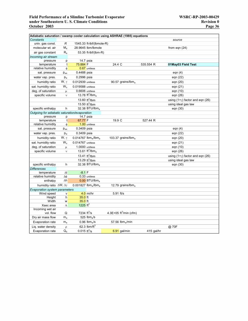
Field Performance of a Slimline Turbomist Evaporator WSRC-RP-2003-00429 under Southeastern U. S. Climate Conditions Revision 0 October 2003 Page 36 Adiabatic saturation / swamp cooler calculation using ASHRAE (1985) equationsConstants source
univ. gas const. R 1545.33 ft-lbf/(lbmole-R)molecular wt. air Ma 28.9645 lbm/lbmole from eqn (24)air gas constant Ra 53.35 ft-lbf/(lbm-R)
Incoming air streampressure p 14.7 psia
temperature t 75.884 F 24.4 C 535.554 R 01May03 Field Testrelative humidity φ 0.67 unitless
sat. pressure pws 0.4488 psia eqn (4)water vap. pres. pw 0.2996 psia eqn (22)
humidity ratio W, γ 0.012939 unitless 90.57 grains/lbma eqn (20)sat. humidity ratio Ws 0.019588 unitless eqn (21)deg. of saturation µ 0.6606 unitless eqn (10)
specific volume ν 13.78 ft3/lbma eqn (26)13.60 ft3/lbm using (1+γ) factor and eqn (26)13.50 ft3/lbm using ideal gas law
specific enthalpy h 32.38 BTU/lbma eqn (30)Outgoing for adiabatic saturation/evaporation
pressure p 14.7 psiatemperature t 67.77 F 19.9 C 527.44 R
relative humidity φ 1.00 unitlesssat. pressure pws 0.3409 psia eqn (4)
water vap. pres. pw 0.3409 psia eqn (22)humidity ratio W, γ 0.014767 lbmw/lbma 103.37 grains/lbma eqn (20)
sat. humidity ratio Ws 0.014767 unitless eqn (21)deg. of saturation µ 1.0000 unitless eqn (10)
specific volume ν 13.61 ft3/lbma eqn (26)13.41 ft3/lbm using (1+γ) factor and eqn (26)13.29 ft3/lbm using ideal gas law
specific enthalpy h 32.38 BTU/lbma eqn (30)Differences
temperature ∆t -8.1 Frelative humidity ∆φ 0.33 unitless
enthalpy ∆h 0.00 BTU/lbma
humidity ratio ∆W, ∆γ 0.001827 lbmw/lbma 12.79 grains/lbma
Evaporation system parametersWind speed v 4.0 mi/hr 5.91 ft/s
Height h 35.0 ftWidth w 35.0 ft
Xsec area Α 1225 ft2
Incoming wet air vol. flow Q 7234 ft3/s 4.3E+05 ft3/min (cfm)
Dry air mass flow ma 525 lbma/sEvaporation rate me 0.96 lbmw/s 57.56 lbmw/min
Liq. water density ρ 62.3 lbm/ft3 @ 70FEvaporation rate Qe 0.015 ft3/s 6.91 gal/min 415 gal/hr
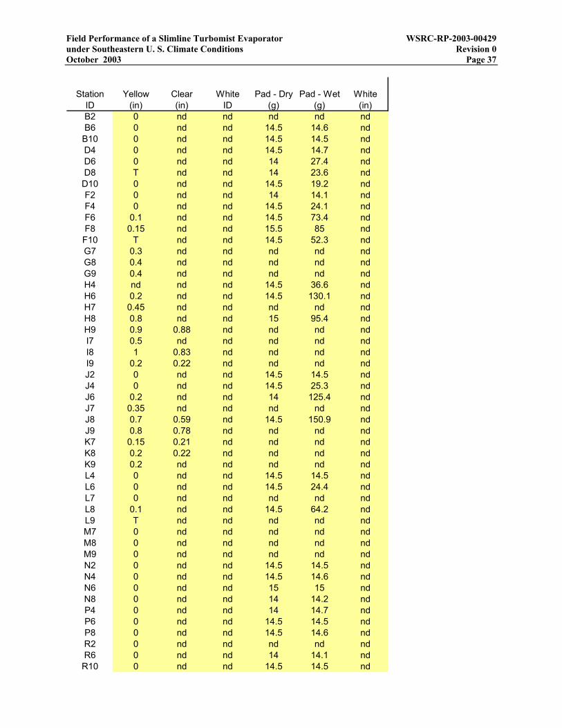
Field Performance of a Slimline Turbomist Evaporator WSRC-RP-2003-00429 under Southeastern U. S. Climate Conditions Revision 0 October 2003 Page 37
Station Yellow Clear White Pad - Dry Pad - Wet WhiteID (in) (in) ID (g) (g) (in)B2 0 nd nd nd nd ndB6 0 nd nd 14.5 14.6 ndB10 0 nd nd 14.5 14.5 ndD4 0 nd nd 14.5 14.7 ndD6 0 nd nd 14 27.4 ndD8 T nd nd 14 23.6 ndD10 0 nd nd 14.5 19.2 ndF2 0 nd nd 14 14.1 ndF4 0 nd nd 14.5 24.1 ndF6 0.1 nd nd 14.5 73.4 ndF8 0.15 nd nd 15.5 85 ndF10 T nd nd 14.5 52.3 ndG7 0.3 nd nd nd nd ndG8 0.4 nd nd nd nd ndG9 0.4 nd nd nd nd ndH4 nd nd nd 14.5 36.6 ndH6 0.2 nd nd 14.5 130.1 ndH7 0.45 nd nd nd nd ndH8 0.8 nd nd 15 95.4 ndH9 0.9 0.88 nd nd nd ndI7 0.5 nd nd nd nd ndI8 1 0.83 nd nd nd ndI9 0.2 0.22 nd nd nd ndJ2 0 nd nd 14.5 14.5 ndJ4 0 nd nd 14.5 25.3 ndJ6 0.2 nd nd 14 125.4 ndJ7 0.35 nd nd nd nd ndJ8 0.7 0.59 nd 14.5 150.9 ndJ9 0.8 0.78 nd nd nd ndK7 0.15 0.21 nd nd nd ndK8 0.2 0.22 nd nd nd ndK9 0.2 nd nd nd nd ndL4 0 nd nd 14.5 14.5 ndL6 0 nd nd 14.5 24.4 ndL7 0 nd nd nd nd ndL8 0.1 nd nd 14.5 64.2 ndL9 T nd nd nd nd ndM7 0 nd nd nd nd ndM8 0 nd nd nd nd ndM9 0 nd nd nd nd ndN2 0 nd nd 14.5 14.5 ndN4 0 nd nd 14.5 14.6 ndN6 0 nd nd 15 15 ndN8 0 nd nd 14 14.2 ndP4 0 nd nd 14 14.7 ndP6 0 nd nd 14.5 14.5 ndP8 0 nd nd 14.5 14.6 ndR2 0 nd nd nd nd ndR6 0 nd nd 14 14.1 ndR10 0 nd nd 14.5 14.5 nd

Field Performance of a Slimline Turbomist Evaporator WSRC-RP-2003-00429 under Southeastern U. S. Climate Conditions Revision 0 October 2003 Page 38
Station Yellow Clear White Pad - Dry Pad - Wet WhiteID (in) (in) ID (g) (g) (in)
B14 0 nd nd nd nd ndD12 0 nd nd 14.5 14.6 ndD14 0 nd nd nd nd ndF12 0 nd nd 14 14.1 ndF14 0 nd nd 14.5 14.6 ndG10 0 nd nd nd nd ndG11 0 nd nd nd nd ndG12 0 nd nd nd nd ndG13 nd nd nd nd nd ndH10 0.2 nd nd 14.5 137.1 ndH11 0 nd nd nd nd ndH12 0 nd nd 14 14.1 ndH13 nd nd nd nd nd ndH14 0 nd nd 15 15 ndI10 0.7 nd nd nd nd ndI11 0 nd nd nd nd ndI12 0 nd nd nd nd ndI13 nd nd nd nd nd ndJ10 0.5 nd nd 14.5 140 ndJ11 nd nd nd nd nd ndJ12 0 nd nd 14 14.4 ndJ13 nd nd nd 14.5 14.5 ndJ14 0 nd nd 14.5 14.5 ndK10 0.1 nd nd nd nd ndK11 0 nd nd nd nd ndK12 0 nd nd nd nd ndK13 nd nd nd nd nd ndL10 0 nd nd 14.5 17.3 ndL11 0 nd nd nd nd ndL12 0 nd nd 14.5 14.5 ndL13 nd nd nd nd nd ndL14 0 nd nd 14.5 14.5 ndM10 0 nd nd nd nd ndM11 0 nd nd nd nd ndM12 0 nd nd nd nd ndM13 nd nd nd nd nd ndN10 0 nd nd 14 14.3 ndN12 0 nd nd 14.5 14.6 ndN14 0 nd nd 14.5 14.5 ndP10 0 nd nd 14.5 14.7 ndP12 0 nd nd 15 15 ndP14 0 nd nd nd nd ndR14 0 nd nd nd nd nd

Field Performance of a Slimline Turbomist Evaporator WSRC-RP-2003-00429 under Southeastern U. S. Climate Conditions Revision 0 October 2003 Page 39
Appendix D – Data and analysis for Turbo-Mist field test on 5/14/03
30 No. 25 cores with D5 orifice plates 14-May-0330 Number of spray nozzles 0.000557 yr Duration of test25 Cores 0.2035 dayD5 Orifices 4.88 hr
5/14/03 10:07 37755.4215 Start of test 293 min21258.9 gal m3 T1-Nozzle flow totalizer 17580 sec
16.3 gal/min m3/hr Nozzle flowrate - indicated 4895.3 gal 18.5 m3 Spray volume248970 gal m3 T2-Bypass flow totalizer 30480 gal 115.4 m3 Bypass volume
109.8 gal/min m3/hr Bypass flowrate - indicated96 psi Pa P1 16.7 gal/min 3.79 m3/hr Spray flowrate92 psi Pa P2 104 gal/min 23.6 m3/hr Bypass flowrate92 psi Pa P3 21 in2 0.0135 m2 Pad area
5/14/03 12:01 37755.5007 Midpoint 0.1458 ft2
23186.5 gal m3 Nozzle flow totalizer 3.35E-06 acre17 gal/min m3/hr Nozzle flowrate - indicated 490 volts Voltage
260960 gal m3 Bypass flow totalizer 35 amps Current104.2 gal/min m3/hr Bypass flowrate - indicated 29.7 kW Power
102 psi Pa P1 72.4 F 22.47 C Temperature98 psi Pa P2 46% 46% Relative humidity98 psi Pa P3 2.0 mph 0.91 m/s Wind speed
5/14/03 15:00 37755.625 End of test 136.20 deg 136.20 deg Wind direction26154.2 gal m3 Nozzle flow totalizer 16.71 gpm Spray
16.6 gal/min m3/hr Nozzle flowrate - indicated 11.00 gpm Fallback279450 gal m3 Bypass flow totalizer 5.71 gpm Evaporation
103.8 gal/min m3/hr Bypass flowrate - indicated 34%100 psi Pa P1 29.7 kW Power96 psi Pa P2 0.08 $/kW-hr Energy cost96 psi Pa P3 0.007 $/gal Cost3 in Pad width 0.056 $/gal Direct heating cost7 in Pad length 12% Relative cost

Field Performance of a Slimline Turbomist Evaporator WSRC-RP-2003-00429 under Southeastern U. S. Climate Conditions Revision 0 October 2003 Page 40 Adiabatic saturation / swamp cooler calculation using ASHRAE (1985) equationsConstants source
univ. gas const. R 1545.33 ft-lbf/(lbmole-R)molecular wt. air Ma 28.9645 lbm/lbmole from eqn (24)air gas constant Ra 53.35 ft-lbf/(lbm-R)
Incoming air streampressure p 14.7 psia
temperature t 72.446 F 22.5 C 532.116 R 14May03 Field Testrelative humidity φ 0.46 unitless
sat. pressure pws 0.3999 psia eqn (4)water vap. pres. pw 0.1839 psia eqn (22)
humidity ratio W, γ 0.007881 unitless 55.16 grains/lbma eqn (20)sat. humidity ratio Ws 0.017394 unitless eqn (21)deg. of saturation µ 0.4531 unitless eqn (10)
specific volume ν 13.58 ft3/lbma eqn (26)13.48 ft3/lbm using (1+γ) factor and eqn (26)13.41 ft3/lbm using ideal gas law
specific enthalpy h 26.00 BTU/lbma eqn (30)Outgoing for adiabatic saturation/evaporation
pressure p 14.7 psiatemperature t 59.18 F 15.1 C 518.85 R
relative humidity φ 1.00 unitlesssat. pressure pws 0.2521 psia eqn (4)
water vap. pres. pw 0.2521 psia eqn (22)humidity ratio W, γ 0.010853 lbmw/lbma 75.97 grains/lbma eqn (20)
sat. humidity ratio Ws 0.010853 unitless eqn (21)deg. of saturation µ 1.0000 unitless eqn (10)
specific volume ν 13.31 ft3/lbma eqn (26)13.16 ft3/lbm using (1+γ) factor and eqn (26)13.08 ft3/lbm using ideal gas law
specific enthalpy h 26.00 BTU/lbma eqn (30)Differences
temperature ∆t -13.3 Frelative humidity ∆φ 0.54 unitless
enthalpy ∆h 0.00 BTU/lbma
humidity ratio ∆W, ∆γ 0.002972 lbmw/lbma 20.81 grains/lbma
Evaporation system parametersWind speed v 2.0 mi/hr 2.99 ft/s
Height h 35.0 ftWidth w 35.0 ft
Xsec area Α 1225 ft2
Incoming wet air vol. flow Q 3657 ft3/s 2.2E+05 ft3/min (cfm)
Dry air mass flow ma 269 lbma/sEvaporation rate me 0.80 lbmw/s 48.03 lbmw/min
Liq. water density ρ 62.3 lbm/ft3 @ 70FEvaporation rate Qe 0.013 ft3/s 5.77 gal/min 346 gal/hr
Field Performance of a Slimline Turbomist Evaporator WSRC-RP-2003-00429 under Southeastern U. S. Climate Conditions Revision 0 October 2003 Page 41
Station Yellow Clear White Pad - Dry Pad - Wet WhiteID (in) (in) ID (g) (g) (in)B2 T nd nd nd nd ndB6 0 nd nd 14.3 14.3 ndB10 0 nd nd 14.6 14.7 ndD4 0 nd nd 14.9 14.9 ndD6 T nd nd 14.2 14.2 ndD8 0 nd nd 14.2 14.2 ndD10 0 nd nd 14.3 14.3 ndF2 0 nd nd 14.3 14.4 ndF4 0 nd nd 15 15 ndF6 0 nd nd 15.1 15.1 ndF8 0 nd nd 14.7 14.8 ndF10 0 nd nd 14.5 14.5 ndG7 T nd nd nd nd ndG8 0 nd nd nd nd ndG9 0 nd nd nd nd ndH4 0 nd nd 14.4 16 ndH6 0 nd nd 14.4 40.7 ndH7 T nd nd nd nd ndH8 0.5 nd nd 14.7 36.1 ndH9 T 0.4 nd nd nd ndI7 0.25 nd nd nd nd ndI8 0.35 0.3 nd nd nd ndI9 0.3 0.27 nd nd nd ndJ2 0.1 nd nd 14.8 15 ndJ4 0 nd nd 14.2 35.1 ndJ6 0.3 nd nd 14.6 136.3 ndJ7 0.6 nd nd nd nd ndJ8 1.3 1.15 nd 14.6 98.4 ndJ9 2 1.6 nd nd nd ndK7 0.5 nd nd nd nd ndK8 0.75 0.7 nd nd nd ndK9 0.8 0.65 nd nd nd ndL4 0 nd nd 14.4 22.4 ndL6 0.1 nd nd 14.4 84 ndL7 0.25 nd nd nd nd ndL8 0.35 nd nd 14.1 104.7 ndL9 0.3 nd nd nd nd ndM7 0.1 nd nd nd nd ndM8 0.1 nd nd nd nd ndM9 T nd nd nd nd ndN2 0 nd nd 14.8 14.9 ndN4 T nd nd 14.6 16.5 ndN6 T nd nd 14.2 30.6 ndN8 0 nd nd 14.5 28.5 ndP4 0 nd nd 14.4 14.6 ndP6 0 nd nd 14.7 15.9 ndP8 0 nd nd 14.8 15.1 ndR2 0 nd nd nd nd ndR6 0 nd nd 14.5 14.5 ndR10 0 nd nd 14.3 14.3 nd
Field Performance of a Slimline Turbomist Evaporator WSRC-RP-2003-00429 under Southeastern U. S. Climate Conditions Revision 0 October 2003 Page 42
Station Yellow Clear White Pad - Dry Pad - Wet WhiteID (in) (in) ID (g) (g) (in)
B14 0 nd nd nd nd ndD12 0 nd nd 14.6 14.6 ndD14 0 nd nd nd nd ndF12 0 nd nd 14.3 14.3 ndF14 0 nd nd 14.5 14.5 ndG10 0 nd nd nd nd ndG11 0 nd nd nd nd ndG12 0 nd nd nd nd ndG13 nd nd nd nd nd ndH10 T T nd 14.7 20 ndH11 0 nd nd nd nd ndH12 0 nd nd 14.4 14.4 ndH13 nd nd nd nd nd ndH14 0 nd nd 14.4 14.4 ndI10 0.1 nd nd nd nd ndI11 0.1 nd nd nd nd ndI12 0 nd nd nd nd ndI13 nd nd nd nd nd ndJ10 1.5 nd nd 14.4 177.7 ndJ11 nd nd nd nd nd ndJ12 0 nd nd 14.5 14.5 ndJ13 nd nd nd 14.5 14.5 ndJ14 0 nd nd 14.5 14.5 ndK10 0.2 nd nd nd nd ndK11 T nd nd nd nd ndK12 0 nd nd nd nd ndK13 nd nd nd nd nd ndL10 0.1 0.05 nd 14.2 45.5 ndL11 0 nd nd nd nd ndL12 0 nd nd 13.9 13.9 ndL13 nd nd nd nd nd ndL14 0 nd nd 14.4 14.4 ndM10 T nd nd nd nd ndM11 0 nd nd nd nd ndM12 0 nd nd nd nd ndM13 nd nd nd nd nd ndN10 T nd nd 14.7 15.6 ndN12 0 nd nd 14.4 14.5 ndN14 0 nd nd 15 15 ndP10 0 nd nd 14.3 14.4 ndP12 0 nd nd 14.5 14.5 ndP14 0 nd nd nd nd ndR14 0 nd nd nd nd nd
Field Performance of a Slimline Turbomist Evaporator WSRC-RP-2003-00429 under Southeastern U. S. Climate Conditions Revision 0 October 2003 Page 43
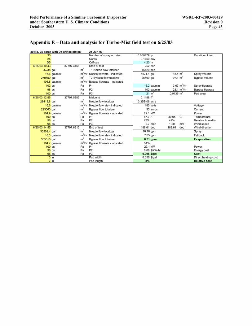
Appendix E – Data and analysis for Turbo-Mist field test on 6/25/03
30 No. 25 cores with D5 orifice plates 25-Jun-0330 Number of spray nozzles 0.000479 yr Duration of test25 Cores 0.1750 dayD5 Orifices 4.20 hr
6/25/03 10:43 37797.4465 Start of test 252 min26238 gal m3 T1-Nozzle flow totalizer 15120 sec
16.6 gal/min m3/hr Nozzle flowrate - indicated 4071.4 gal 15.4 m3 Spray volume279850 gal m3 T2-Bypass flow totalizer 25660 gal 97.1 m3 Bypass volume
106.8 gal/min m3/hr Bypass flowrate - indicated102 psi Pa P1 16.2 gal/min 3.67 m3/hr Spray flowrate98 psi Pa P2 102 gal/min 23.1 m3/hr Bypass flowrate
100 psi Pa P3 21 in2 0.0135 m2 Pad area6/25/03 12:55 37797.5382 Midpoint 0.1458 ft2
28413.8 gal m3 Nozzle flow totalizer 3.35E-06 acre16.6 gal/min m3/hr Nozzle flowrate - indicated 480 volts Voltage
293560 gal m3 Bypass flow totalizer 35 amps Current104.9 gal/min m3/hr Bypass flowrate - indicated 29.1 kW Power
100 psi Pa P1 87.7 F 30.95 C Temperature96 psi Pa P2 42% 42% Relative humidity98 psi Pa P3 2.7 mph 1.20 m/s Wind speed
6/25/03 14:55 37797.6215 End of test 188.61 deg 188.61 deg Wind direction30309.4 gal m3 Nozzle flow totalizer 16.16 gpm Spray
16.3 gal/min m3/hr Nozzle flowrate - indicated 7.85 gpm Fallback305510 gal m3 Bypass flow totalizer 8.31 gpm Evaporation
104.7 gal/min m3/hr Bypass flowrate - indicated 51%100 psi Pa P1 29.1 kW Power96 psi Pa P2 0.08 $/kW-hr Energy cost98 psi Pa P3 0.005 $/gal Cost3 in Pad width 0.056 $/gal Direct heating cost7 in Pad length 8% Relative cost

Field Performance of a Slimline Turbomist Evaporator WSRC-RP-2003-00429 under Southeastern U. S. Climate Conditions Revision 0 October 2003 Page 44 Adiabatic saturation / swamp cooler calculation using ASHRAE (1985) equationsConstants source
univ. gas const. R 1545.33 ft-lbf/(lbmole-R)molecular wt. air Ma 28.9645 lbm/lbmole from eqn (24)air gas constant Ra 53.35 ft-lbf/(lbm-R)
Incoming air streampressure p 14.7 psia
temperature t 87.71 F 31.0 C 547.38 R 25Jun03 Field Testrelative humidity φ 0.42 unitless
sat. pressure pws 0.6591 psia eqn (4)water vap. pres. pw 0.2775 psia eqn (22)
humidity ratio W, γ 0.011966 unitless 83.76 grains/lbma eqn (20)sat. humidity ratio Ws 0.029195 unitless eqn (21)deg. of saturation µ 0.4099 unitless eqn (10)
specific volume ν 14.06 ft3/lbma eqn (26)13.90 ft3/lbm using (1+γ) factor and eqn (26)13.80 ft3/lbm using ideal gas law
specific enthalpy h 34.21 BTU/lbma eqn (30)Outgoing for adiabatic saturation/evaporation
pressure p 14.7 psiatemperature t 69.96 F 21.1 C 529.63 R
relative humidity φ 1.00 unitlesssat. pressure pws 0.3676 psia eqn (4)
water vap. pres. pw 0.3676 psia eqn (22)humidity ratio W, γ 0.015952 lbmw/lbma 111.66 grains/lbma eqn (20)
sat. humidity ratio Ws 0.015952 unitless eqn (21)deg. of saturation µ 1.0000 unitless eqn (10)
specific volume ν 13.69 ft3/lbma eqn (26)13.48 ft3/lbm using (1+γ) factor and eqn (26)13.35 ft3/lbm using ideal gas law
specific enthalpy h 34.21 BTU/lbma eqn (30)Differences
temperature ∆t -17.7 Frelative humidity ∆φ 0.58 unitless
enthalpy ∆h 0.00 BTU/lbma
humidity ratio ∆W, ∆γ 0.003986 lbmw/lbma 27.90 grains/lbma
Evaporation system parametersWind speed v 2.7 mi/hr 3.94 ft/s
Height h 35.0 ftWidth w 35.0 ft
Xsec area Α 1225 ft2
Incoming wet air vol. flow Q 4823 ft3/s 2.9E+05 ft3/min (cfm)
Dry air mass flow ma 343 lbma/sEvaporation rate me 1.37 lbmw/s 82.03 lbmw/min
Liq. water density ρ 62.3 lbm/ft3 @ 70FEvaporation rate Qe 0.022 ft3/s 9.85 gal/min 591 gal/hr
Field Performance of a Slimline Turbomist Evaporator WSRC-RP-2003-00429 under Southeastern U. S. Climate Conditions Revision 0 October 2003 Page 45
Station Yellow Clear White Pad - Dry Pad - Wet WhiteID (in) (in) ID (g) (g) (in)B2 nd nd nd nd nd ndB6 nd nd nd 14.2 14.2 ndB10 nd nd nd 13.7 13.7 ndD4 nd nd nd 14.4 14.4 ndD6 nd nd nd 14.2 14.2 ndD8 nd nd nd 14.1 14.1 ndD10 nd nd nd 13.9 13.9 ndF2 nd nd nd 14.4 14.4 ndF4 nd nd nd 14.2 14.2 ndF6 nd nd nd 14.3 15 ndF8 0 nd nd 15.1 28 ndF10 0 nd nd 14.1 19.6 ndG7 0 nd nd nd nd ndG8 0 nd nd nd nd ndG9 0.1 nd nd nd nd ndH4 0 nd nd 14.2 14.2 ndH6 T nd nd 14.6 20.9 ndH7 T nd nd nd nd ndH8 0.1 nd nd 13.8 78.6 ndH9 0.2 0.17 nd nd nd ndI7 nd nd nd nd nd ndI8 0.2 0.19 nd nd nd ndI9 0.3 0.36 nd nd nd ndJ2 nd nd nd 14 14 ndJ4 0 nd nd 14.1 14.1 ndJ6 0.1 nd nd 13.9 44.2 ndJ7 0.2 nd nd nd nd ndJ8 0.4 0.38 nd 14.6 89.9 ndJ9 0.7 0.65 nd nd nd ndK7 0.1 nd nd nd nd ndK8 0.2 0.2 nd nd nd ndK9 0.4 0.28 nd nd nd ndL4 0 nd nd 14.2 14.2 ndL6 0.1 nd nd 13.6 16.1 ndL7 T nd nd nd nd ndL8 T nd nd 14.5 49.6 ndL9 0.2 nd nd nd nd ndM7 0.1 nd nd nd nd ndM8 T nd nd nd nd ndM9 T nd nd nd nd ndN2 nd nd nd 14.4 14.4 ndN4 nd nd nd 14.4 14.4 ndN6 0 nd nd 14.5 14.5 ndN8 T nd nd 14.3 15.5 ndP4 nd nd nd 14.5 14.5 ndP6 nd nd nd 14.6 14.6 ndP8 nd nd nd 14.2 14.2 ndR2 nd nd nd nd nd ndR6 nd nd nd 13.9 13.9 ndR10 nd nd nd 13.8 13.8 nd

Field Performance of a Slimline Turbomist Evaporator WSRC-RP-2003-00429 under Southeastern U. S. Climate Conditions Revision 0 October 2003 Page 46
Station Yellow Clear White Pad - Dry Pad - Wet WhiteID (in) (in) ID (g) (g) (in)
B14 T nd nd nd nd ndD12 nd nd nd 14.2 14.2 ndD14 T nd nd nd nd ndF12 0 nd nd 14 14 ndF14 0 nd nd 14.2 14.2 ndG10 0 nd nd nd nd ndG11 T nd nd nd nd ndG12 0 nd nd nd nd ndG13 nd nd nd nd nd ndH10 0.1 0.07 nd 14.4 70.5 ndH11 nd nd nd nd nd ndH12 0 nd nd 14.4 15.5 ndH13 nd nd nd nd nd ndH14 0 nd nd 14.2 14.2 ndI10 0.3 nd nd nd nd ndI11 0.2 nd nd nd nd ndI12 nd nd nd nd nd ndI13 nd nd nd nd nd ndJ10 0.9 nd nd 14.2 138.8 ndJ11 nd nd nd nd nd ndJ12 nd nd nd 14 21.2 ndJ13 nd nd nd nd nd ndJ14 0 nd nd 14.4 14.4 ndK10 nd nd nd nd nd ndK11 0.2 nd nd nd nd ndK12 0.2 nd nd nd nd ndK13 nd nd nd nd nd ndL10 T 0.04 nd 14.1 36.1 ndL11 0.2 nd nd nd nd ndL12 0 nd nd 14 14 ndL13 nd nd nd nd nd ndL14 0 nd nd 14.1 14.1 ndM10 0 nd nd nd nd ndM11 0 nd nd nd nd ndM12 0 nd nd nd nd ndM13 nd nd nd nd nd ndN10 0 nd nd 14 14.1 ndN12 0 nd nd 14.1 14.1 ndN14 nd nd nd 14.3 14.3 ndP10 0 nd nd 14.2 14.2 ndP12 nd nd nd 14.2 14.2 ndP14 nd nd nd nd nd ndR14 nd nd nd nd nd nd

Field Performance of a Slimline Turbomist Evaporator WSRC-RP-2003-00429 under Southeastern U. S. Climate Conditions Revision 0 October 2003 Page 47
Appendix F – Data and analysis for Turbo-Mist field test on 6/26/03
27 No. 45 cores with D6 orifice plates 26-Jun-0327 Number of spray nozzles 0.000464 yr Duration of test45 Cores 0.1694 dayD6 Orifices 4.07 hr
6/26/03 10:50 37798.4514 Start of test 244 min30418.4 gal m3 T1-Nozzle flow totalizer 14640 sec
26.1 gal/min m3/hr Nozzle flowrate - indicated 6211.4 gal 23.5 m3 Spray volume305990 gal m3 T2-Bypass flow totalizer 22500 gal 85.2 m3 Bypass volume
94.1 gal/min m3/hr Bypass flowrate - indicated104 psi Pa P1 25.5 gal/min 5.78 m3/hr Spray flowrate100 psi Pa P2 92 gal/min 20.9 m3/hr Bypass flowrate100 psi Pa P3 21 in2 0.0135 m2 Pad area
6/26/03 13:00 37798.5417 Midpoint 0.1458 ft2
33783.1 gal m3 Nozzle flow totalizer 3.35E-06 acre26.1 gal/min m3/hr Nozzle flowrate - indicated 480 volts Voltage
318180 gal m3 Bypass flow totalizer 35 amps Current94.2 gal/min m3/hr Bypass flowrate - indicated 29.1 kW Power104 psi Pa P1 87.3 F 30.70 C Temperature100 psi Pa P2 48% 48% Relative humidity100 psi Pa P3 4.6 mph 2.04 m/s Wind speed
6/26/03 14:54 37798.6208 End of test 245.89 deg 245.89 deg Wind direction36629.8 gal m3 Nozzle flow totalizer 25.46 gpm Spray
26.1 gal/min m3/hr Nozzle flowrate - indicated 12.28 gpm Fallback328490 gal m3 Bypass flow totalizer 13.17 gpm Evaporation
93.8 gal/min m3/hr Bypass flowrate - indicated 52%102 psi Pa P1 29.1 kW Power100 psi Pa P2 0.08 $/kW-hr Energy cost100 psi Pa P3 0.003 $/gal Cost
3 in Pad width 0.056 $/gal Direct heating cost7 in Pad length 5% Relative cost

Field Performance of a Slimline Turbomist Evaporator WSRC-RP-2003-00429 under Southeastern U. S. Climate Conditions Revision 0 October 2003 Page 48 Adiabatic saturation / swamp cooler calculation using ASHRAE (1985) equationsConstants source
univ. gas const. R 1545.33 ft-lbf/(lbmole-R)molecular wt. air Ma 28.9645 lbm/lbmole from eqn (24)air gas constant Ra 53.35 ft-lbf/(lbm-R)
Incoming air streampressure p 14.7 psia
temperature t 87.259 F 30.7 C 546.929 R 26Jun03 Field Testrelative humidity φ 0.48 unitless
sat. pressure pws 0.6497 psia eqn (4)water vap. pres. pw 0.3102 psia eqn (22)
humidity ratio W, γ 0.013409 unitless 93.87 grains/lbma eqn (20)sat. humidity ratio Ws 0.028761 unitless eqn (21)deg. of saturation µ 0.4662 unitless eqn (10)
specific volume ν 14.08 ft3/lbma eqn (26)13.90 ft3/lbm using (1+γ) factor and eqn (26)13.78 ft3/lbm using ideal gas law
specific enthalpy h 35.69 BTU/lbma eqn (30)Outgoing for adiabatic saturation/evaporation
pressure p 14.7 psiatemperature t 71.65 F 22.0 C 531.32 R
relative humidity φ 1.00 unitlesssat. pressure pws 0.3893 psia eqn (4)
water vap. pres. pw 0.3893 psia eqn (22)humidity ratio W, γ 0.016921 lbmw/lbma 118.45 grains/lbma eqn (20)
sat. humidity ratio Ws 0.016921 unitless eqn (21)deg. of saturation µ 1.0000 unitless eqn (10)
specific volume ν 13.76 ft3/lbma eqn (26)13.53 ft3/lbm using (1+γ) factor and eqn (26)13.39 ft3/lbm using ideal gas law
specific enthalpy h 35.69 BTU/lbma eqn (30)Differences
temperature ∆t -15.6 Frelative humidity ∆φ 0.52 unitless
enthalpy ∆h 0.00 BTU/lbma
humidity ratio ∆W, ∆γ 0.003512 lbmw/lbma 24.58 grains/lbma
Evaporation system parametersWind speed v 4.6 mi/hr 6.69 ft/s
Height h 35.0 ftWidth w 35.0 ft
Xsec area Α 1225 ft2
Incoming wet air vol. flow Q 8192 ft3/s 4.9E+05 ft3/min (cfm)
Dry air mass flow ma 582 lbma/sEvaporation rate me 2.04 lbmw/s 122.57 lbmw/min
Liq. water density ρ 62.3 lbm/ft3 @ 70FEvaporation rate Qe 0.033 ft3/s 14.72 gal/min 883 gal/hr

Field Performance of a Slimline Turbomist Evaporator WSRC-RP-2003-00429 under Southeastern U. S. Climate Conditions Revision 0 October 2003 Page 49
Station Yellow Clear White Pad - Dry Pad - Wet WhiteID (in) (in) ID (g) (g) (in)B2 nd nd nd nd nd ndB6 nd nd nd 14.3 14.3 ndB10 nd nd nd 13.9 13.9 ndD4 nd nd nd 14.1 14.1 ndD6 nd nd nd 14.2 14.2 ndD8 nd nd nd 14.2 14.2 ndD10 nd nd nd 14.4 14.4 ndF2 nd nd nd 14.3 14.3 ndF4 0 nd nd 14 14 ndF6 0 nd nd 14 14 ndF8 0 nd nd 14.2 14.2 ndF10 0 nd nd 14.4 14.4 ndG7 0 nd nd nd nd ndG8 nd nd nd nd nd ndG9 0 nd nd nd nd ndH4 0 nd nd 14.1 14.1 ndH6 0 nd nd 14 14 ndH7 0 nd nd nd nd ndH8 0 nd nd 14.2 14.2 ndH9 0 0.02 nd nd nd ndI7 0 nd nd nd nd ndI8 0 0.04 nd nd nd ndI9 0 0.05 nd nd nd ndJ2 0 nd nd 14.1 14.1 ndJ4 0 nd nd 13.7 13.7 ndJ6 0 nd nd 14.1 14.1 ndJ7 0 nd nd nd nd ndJ8 0.1 0.15 nd 14 88.9 ndJ9 0.4 0.42 nd nd nd ndK7 0 nd nd nd nd ndK8 0.1 0.12 nd nd nd ndK9 0.4 0.45 nd nd nd ndL4 0 nd nd 14.3 14.3 ndL6 0 nd nd 14 14 ndL7 0 nd nd nd nd ndL8 0.1 nd nd 14.4 71.2 ndL9 0.4 nd nd nd nd ndM7 0 nd nd nd nd ndM8 0.1 nd nd nd nd ndM9 0.3 nd nd nd nd ndN2 nd nd nd 14 14 ndN4 0 nd nd 13.9 13.9 ndN6 0 nd nd 14.1 14.1 ndN8 T nd nd 14 34.7 ndP4 nd nd nd 13.7 13.7 ndP6 nd nd nd 14 14 ndP8 nd nd nd 13.6 16.3 ndR2 nd nd nd nd nd ndR6 nd nd nd 14.1 14.1 ndR10 nd nd nd 14.4 15.7 nd
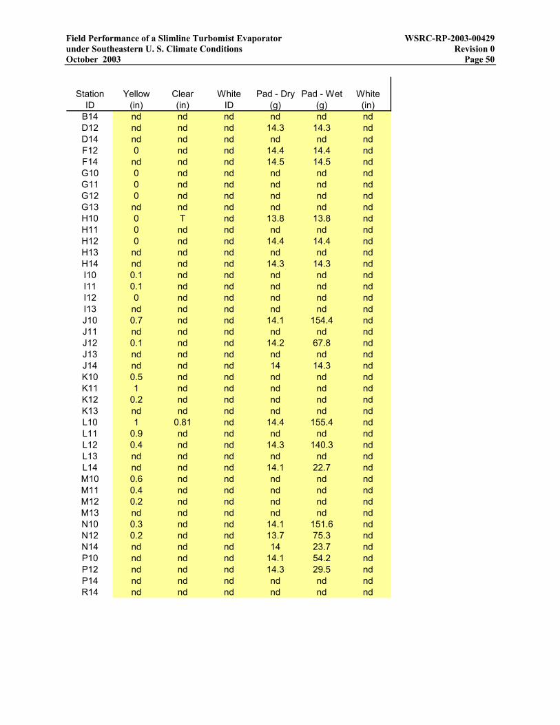
Field Performance of a Slimline Turbomist Evaporator WSRC-RP-2003-00429 under Southeastern U. S. Climate Conditions Revision 0 October 2003 Page 50
Station Yellow Clear White Pad - Dry Pad - Wet WhiteID (in) (in) ID (g) (g) (in)
B14 nd nd nd nd nd ndD12 nd nd nd 14.3 14.3 ndD14 nd nd nd nd nd ndF12 0 nd nd 14.4 14.4 ndF14 nd nd nd 14.5 14.5 ndG10 0 nd nd nd nd ndG11 0 nd nd nd nd ndG12 0 nd nd nd nd ndG13 nd nd nd nd nd ndH10 0 T nd 13.8 13.8 ndH11 0 nd nd nd nd ndH12 0 nd nd 14.4 14.4 ndH13 nd nd nd nd nd ndH14 nd nd nd 14.3 14.3 ndI10 0.1 nd nd nd nd ndI11 0.1 nd nd nd nd ndI12 0 nd nd nd nd ndI13 nd nd nd nd nd ndJ10 0.7 nd nd 14.1 154.4 ndJ11 nd nd nd nd nd ndJ12 0.1 nd nd 14.2 67.8 ndJ13 nd nd nd nd nd ndJ14 nd nd nd 14 14.3 ndK10 0.5 nd nd nd nd ndK11 1 nd nd nd nd ndK12 0.2 nd nd nd nd ndK13 nd nd nd nd nd ndL10 1 0.81 nd 14.4 155.4 ndL11 0.9 nd nd nd nd ndL12 0.4 nd nd 14.3 140.3 ndL13 nd nd nd nd nd ndL14 nd nd nd 14.1 22.7 ndM10 0.6 nd nd nd nd ndM11 0.4 nd nd nd nd ndM12 0.2 nd nd nd nd ndM13 nd nd nd nd nd ndN10 0.3 nd nd 14.1 151.6 ndN12 0.2 nd nd 13.7 75.3 ndN14 nd nd nd 14 23.7 ndP10 nd nd nd 14.1 54.2 ndP12 nd nd nd 14.3 29.5 ndP14 nd nd nd nd nd ndR14 nd nd nd nd nd nd

Field Performance of a Slimline Turbomist Evaporator WSRC-RP-2003-00429 under Southeastern U. S. Climate Conditions Revision 0 October 2003 Page 51
Appendix G – Data and analysis for Turbo-Mist field test on 7/24/03
27 No. 45 cores with D6 orifice plates 24-Jul-0327 Number of spray nozzles 0.000457 yr Duration of test45 Cores 0.1667 dayD6 Orifices 4.00 hr
7/24/03 11:00 37826.4583 Start of test 240 min36736.2 gal m3 T1-Nozzle flow totalizer 14400 sec
26.1 gal/min m3/hr Nozzle flowrate - indicated 6253 gal 23.7 m3 Spray volume328910 gal m3 T2-Bypass flow totalizer 22590 gal 85.5 m3 Bypass volume
94.6 gal/min m3/hr Bypass flowrate - indicated106 psi Pa P1 26.1 gal/min 5.92 m3/hr Spray flowrate102 psi Pa P2 94 gal/min 21.4 m3/hr Bypass flowrate102 psi Pa P3 21 in2 0.0135 m2 Pad area
7/24/03 13:00 37826.5417 Midpoint 0.1458 ft2
39820.1 gal m3 Nozzle flow totalizer 3.35E-06 acre25.7 gal/min m3/hr Nozzle flowrate - indicated 480 volts Voltage
340020 gal m3 Bypass flow totalizer 35 amps Current94.7 gal/min m3/hr Bypass flowrate - indicated 29.1 kW Power103 psi Pa P1 82.5 F 28.0 C Temperature103 psi Pa P2 62% 62% Relative humidity101 psi Pa P3 3.0 mph 1.35 m/s Wind speed
7/24/03 15:00 37826.625 End of test 264.06 deg 264.06 deg Wind direction42989.2 gal m3 Nozzle flow totalizer 26.05 gpm Spray
25.7 gal/min m3/hr Nozzle flowrate - indicated 14.70 gpm Fallback351500 gal m3 Bypass flow totalizer 11.36 gpm Evaporation
94.6 gal/min m3/hr Bypass flowrate - indicated 44%103 psi Pa P1 29.1 kW Power101 psi Pa P2 0.08 $/kW-hr Energy cost101 psi Pa P3 0.003 $/gal Cost
3 in Pad width 0.056 $/gal Direct heating cost7 in Pad length 6% Relative cost
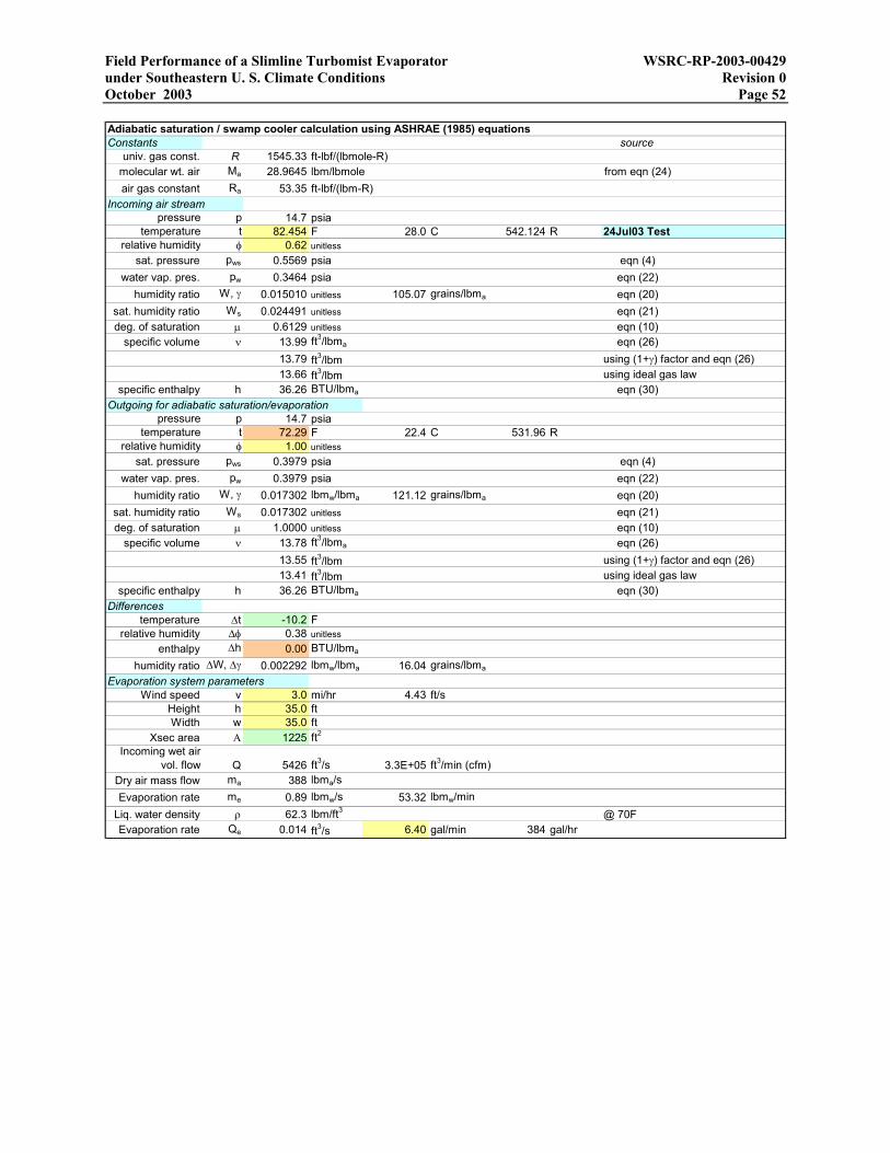
Field Performance of a Slimline Turbomist Evaporator WSRC-RP-2003-00429 under Southeastern U. S. Climate Conditions Revision 0 October 2003 Page 52 Adiabatic saturation / swamp cooler calculation using ASHRAE (1985) equationsConstants source
univ. gas const. R 1545.33 ft-lbf/(lbmole-R)molecular wt. air Ma 28.9645 lbm/lbmole from eqn (24)air gas constant Ra 53.35 ft-lbf/(lbm-R)
Incoming air streampressure p 14.7 psia
temperature t 82.454 F 28.0 C 542.124 R 24Jul03 Testrelative humidity φ 0.62 unitless
sat. pressure pws 0.5569 psia eqn (4)water vap. pres. pw 0.3464 psia eqn (22)
humidity ratio W, γ 0.015010 unitless 105.07 grains/lbma eqn (20)sat. humidity ratio Ws 0.024491 unitless eqn (21)deg. of saturation µ 0.6129 unitless eqn (10)
specific volume ν 13.99 ft3/lbma eqn (26)13.79 ft3/lbm using (1+γ) factor and eqn (26)13.66 ft3/lbm using ideal gas law
specific enthalpy h 36.26 BTU/lbma eqn (30)Outgoing for adiabatic saturation/evaporation
pressure p 14.7 psiatemperature t 72.29 F 22.4 C 531.96 R
relative humidity φ 1.00 unitlesssat. pressure pws 0.3979 psia eqn (4)
water vap. pres. pw 0.3979 psia eqn (22)humidity ratio W, γ 0.017302 lbmw/lbma 121.12 grains/lbma eqn (20)
sat. humidity ratio Ws 0.017302 unitless eqn (21)deg. of saturation µ 1.0000 unitless eqn (10)
specific volume ν 13.78 ft3/lbma eqn (26)13.55 ft3/lbm using (1+γ) factor and eqn (26)13.41 ft3/lbm using ideal gas law
specific enthalpy h 36.26 BTU/lbma eqn (30)Differences
temperature ∆t -10.2 Frelative humidity ∆φ 0.38 unitless
enthalpy ∆h 0.00 BTU/lbma
humidity ratio ∆W, ∆γ 0.002292 lbmw/lbma 16.04 grains/lbma
Evaporation system parametersWind speed v 3.0 mi/hr 4.43 ft/s
Height h 35.0 ftWidth w 35.0 ft
Xsec area Α 1225 ft2
Incoming wet air vol. flow Q 5426 ft3/s 3.3E+05 ft3/min (cfm)
Dry air mass flow ma 388 lbma/sEvaporation rate me 0.89 lbmw/s 53.32 lbmw/min
Liq. water density ρ 62.3 lbm/ft3 @ 70FEvaporation rate Qe 0.014 ft3/s 6.40 gal/min 384 gal/hr
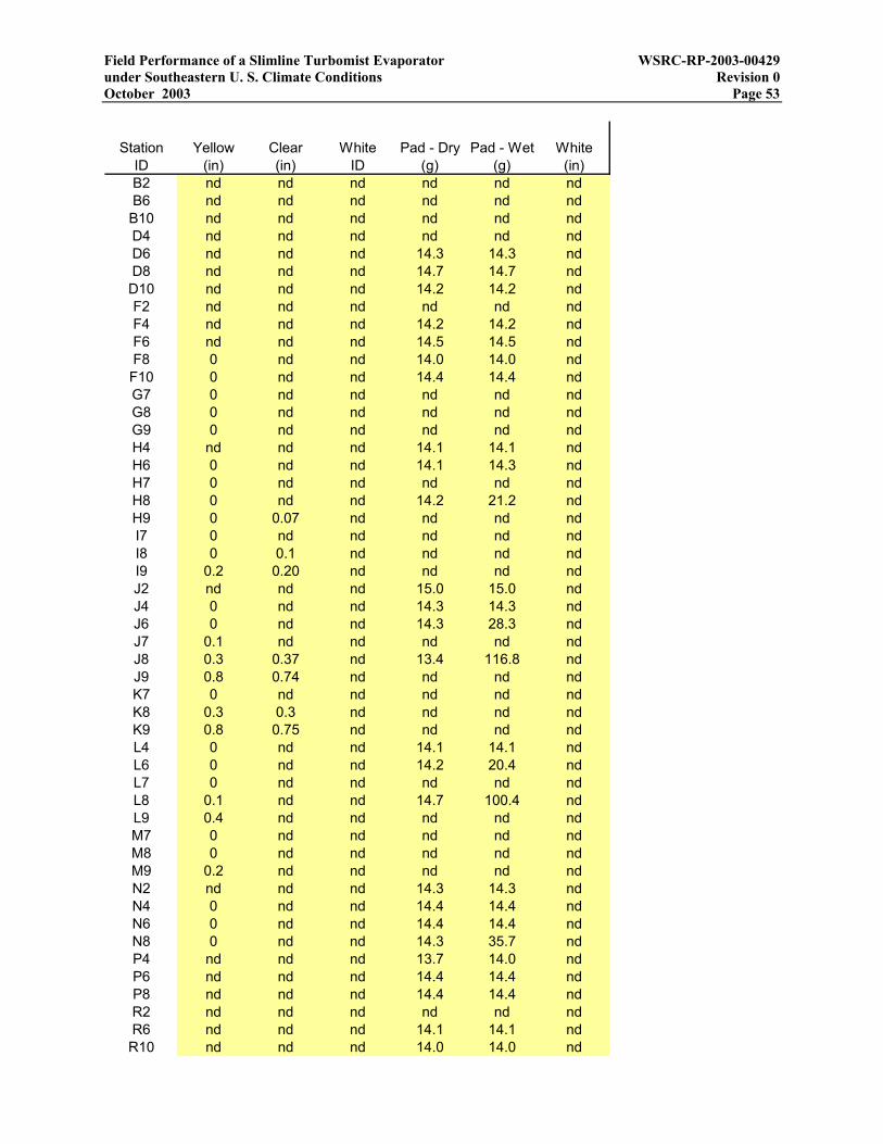
Field Performance of a Slimline Turbomist Evaporator WSRC-RP-2003-00429 under Southeastern U. S. Climate Conditions Revision 0 October 2003 Page 53
Station Yellow Clear White Pad - Dry Pad - Wet WhiteID (in) (in) ID (g) (g) (in)B2 nd nd nd nd nd ndB6 nd nd nd nd nd ndB10 nd nd nd nd nd ndD4 nd nd nd nd nd ndD6 nd nd nd 14.3 14.3 ndD8 nd nd nd 14.7 14.7 ndD10 nd nd nd 14.2 14.2 ndF2 nd nd nd nd nd ndF4 nd nd nd 14.2 14.2 ndF6 nd nd nd 14.5 14.5 ndF8 0 nd nd 14.0 14.0 ndF10 0 nd nd 14.4 14.4 ndG7 0 nd nd nd nd ndG8 0 nd nd nd nd ndG9 0 nd nd nd nd ndH4 nd nd nd 14.1 14.1 ndH6 0 nd nd 14.1 14.3 ndH7 0 nd nd nd nd ndH8 0 nd nd 14.2 21.2 ndH9 0 0.07 nd nd nd ndI7 0 nd nd nd nd ndI8 0 0.1 nd nd nd ndI9 0.2 0.20 nd nd nd ndJ2 nd nd nd 15.0 15.0 ndJ4 0 nd nd 14.3 14.3 ndJ6 0 nd nd 14.3 28.3 ndJ7 0.1 nd nd nd nd ndJ8 0.3 0.37 nd 13.4 116.8 ndJ9 0.8 0.74 nd nd nd ndK7 0 nd nd nd nd ndK8 0.3 0.3 nd nd nd ndK9 0.8 0.75 nd nd nd ndL4 0 nd nd 14.1 14.1 ndL6 0 nd nd 14.2 20.4 ndL7 0 nd nd nd nd ndL8 0.1 nd nd 14.7 100.4 ndL9 0.4 nd nd nd nd ndM7 0 nd nd nd nd ndM8 0 nd nd nd nd ndM9 0.2 nd nd nd nd ndN2 nd nd nd 14.3 14.3 ndN4 0 nd nd 14.4 14.4 ndN6 0 nd nd 14.4 14.4 ndN8 0 nd nd 14.3 35.7 ndP4 nd nd nd 13.7 14.0 ndP6 nd nd nd 14.4 14.4 ndP8 nd nd nd 14.4 14.4 ndR2 nd nd nd nd nd ndR6 nd nd nd 14.1 14.1 ndR10 nd nd nd 14.0 14.0 nd

Field Performance of a Slimline Turbomist Evaporator WSRC-RP-2003-00429 under Southeastern U. S. Climate Conditions Revision 0 October 2003 Page 54
Station Yellow Clear White Pad - Dry Pad - Wet WhiteID (in) (in) ID (g) (g) (in)
B14 nd nd nd nd nd ndD12 nd nd nd 14.5 14.5 ndD14 nd nd nd nd nd ndF12 0 nd nd 14.0 14.2 ndF14 nd nd nd 14.5 14.5 ndG10 0 nd nd nd nd ndG11 0 nd nd nd nd ndG12 0 nd nd nd nd ndG13 nd nd nd nd nd ndH10 0 0.05 nd 14.4 53.3 ndH11 0.1 nd nd nd nd ndH12 0 nd nd 14.3 50.0 ndH13 nd nd nd nd nd ndH14 nd nd nd 14.6 14.6 ndI10 0.3 nd nd nd nd ndI11 0.4 nd nd nd nd ndI12 0.1 nd nd nd nd ndI13 nd nd nd nd nd ndJ10 1.1 nd nd 14.4 158.9 ndJ11 nd nd nd nd nd ndJ12 0.2 nd nd 14.5 143.5 ndJ13 nd nd nd nd nd ndJ14 0 nd nd 14.6 27.0 ndK10 1.2 nd nd nd nd ndK11 1.1 nd nd nd nd ndK12 0.2 nd nd nd nd ndK13 nd nd nd nd nd ndL10 0.6 0.68 nd 14.5 149.7 ndL11 0.7 nd nd nd nd ndL12 0.2 nd nd 14.6 129.5 ndL13 nd nd nd nd nd ndL14 0 nd nd 14.4 24.1 ndM10 0.2 nd nd nd nd ndM11 0.4 nd nd nd nd ndM12 0.1 nd nd nd nd ndM13 nd nd nd nd nd ndN10 0 nd nd 14.6 65.2 ndN12 0.1 nd nd 14.6 77.9 ndN14 0 nd nd 14.5 20.1 ndP10 nd nd nd 14.2 18.2 ndP12 nd nd nd 14.4 26.1 ndP14 nd nd nd 14.2 16.2 ndR14 nd nd nd 14.3 14.3 nd
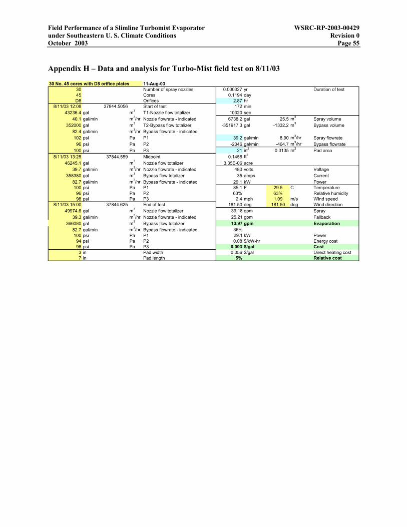
Field Performance of a Slimline Turbomist Evaporator WSRC-RP-2003-00429 under Southeastern U. S. Climate Conditions Revision 0 October 2003 Page 55
Appendix H – Data and analysis for Turbo-Mist field test on 8/11/03
30 No. 45 cores with D8 orifice plates 11-Aug-0330 Number of spray nozzles 0.000327 yr Duration of test45 Cores 0.1194 dayD8 Orifices 2.87 hr
8/11/03 12:08 37844.5056 Start of test 172 min43236.4 gal m3 T1-Nozzle flow totalizer 10320 sec
40.1 gal/min m3/hr Nozzle flowrate - indicated 6738.2 gal 25.5 m3 Spray volume352000 gal m3 T2-Bypass flow totalizer -351917.3 gal -1332.2 m3 Bypass volume
82.4 gal/min m3/hr Bypass flowrate - indicated102 psi Pa P1 39.2 gal/min 8.90 m3/hr Spray flowrate96 psi Pa P2 -2046 gal/min -464.7 m3/hr Bypass flowrate
100 psi Pa P3 21 in2 0.0135 m2 Pad area8/11/03 13:25 37844.559 Midpoint 0.1458 ft2
46245.1 gal m3 Nozzle flow totalizer 3.35E-06 acre39.7 gal/min m3/hr Nozzle flowrate - indicated 480 volts Voltage
358380 gal m3 Bypass flow totalizer 35 amps Current82.7 gal/min m3/hr Bypass flowrate - indicated 29.1 kW Power100 psi Pa P1 85.1 F 29.5 C Temperature96 psi Pa P2 63% 63% Relative humidity98 psi Pa P3 2.4 mph 1.09 m/s Wind speed
8/11/03 15:00 37844.625 End of test 181.50 deg 181.50 deg Wind direction49974.6 gal m3 Nozzle flow totalizer 39.18 gpm Spray
39.3 gal/min m3/hr Nozzle flowrate - indicated 25.21 gpm Fallback366080 gal m3 Bypass flow totalizer 13.97 gpm Evaporation
82.7 gal/min m3/hr Bypass flowrate - indicated 36%100 psi Pa P1 29.1 kW Power94 psi Pa P2 0.08 $/kW-hr Energy cost96 psi Pa P3 0.003 $/gal Cost
3 in Pad width 0.056 $/gal Direct heating cost7 in Pad length 5% Relative cost
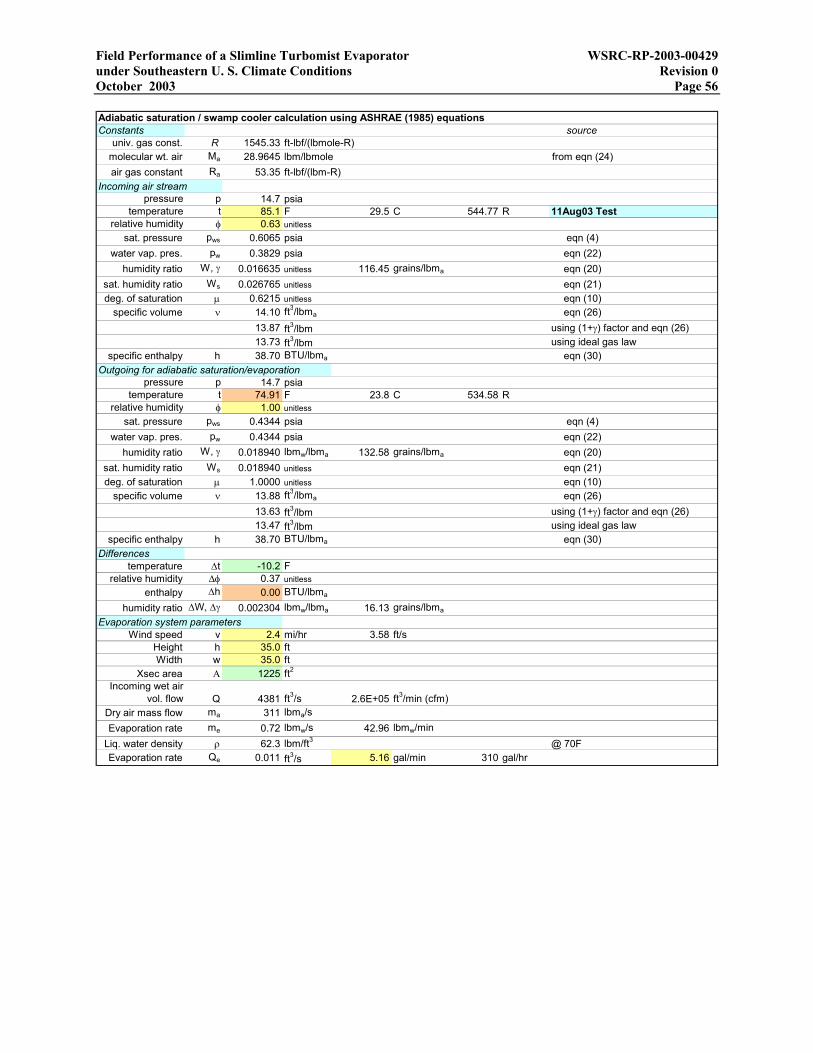
Field Performance of a Slimline Turbomist Evaporator WSRC-RP-2003-00429 under Southeastern U. S. Climate Conditions Revision 0 October 2003 Page 56 Adiabatic saturation / swamp cooler calculation using ASHRAE (1985) equationsConstants source
univ. gas const. R 1545.33 ft-lbf/(lbmole-R)molecular wt. air Ma 28.9645 lbm/lbmole from eqn (24)air gas constant Ra 53.35 ft-lbf/(lbm-R)
Incoming air streampressure p 14.7 psia
temperature t 85.1 F 29.5 C 544.77 R 11Aug03 Testrelative humidity φ 0.63 unitless
sat. pressure pws 0.6065 psia eqn (4)water vap. pres. pw 0.3829 psia eqn (22)
humidity ratio W, γ 0.016635 unitless 116.45 grains/lbma eqn (20)sat. humidity ratio Ws 0.026765 unitless eqn (21)deg. of saturation µ 0.6215 unitless eqn (10)
specific volume ν 14.10 ft3/lbma eqn (26)13.87 ft3/lbm using (1+γ) factor and eqn (26)13.73 ft3/lbm using ideal gas law
specific enthalpy h 38.70 BTU/lbma eqn (30)Outgoing for adiabatic saturation/evaporation
pressure p 14.7 psiatemperature t 74.91 F 23.8 C 534.58 R
relative humidity φ 1.00 unitlesssat. pressure pws 0.4344 psia eqn (4)
water vap. pres. pw 0.4344 psia eqn (22)humidity ratio W, γ 0.018940 lbmw/lbma 132.58 grains/lbma eqn (20)
sat. humidity ratio Ws 0.018940 unitless eqn (21)deg. of saturation µ 1.0000 unitless eqn (10)
specific volume ν 13.88 ft3/lbma eqn (26)13.63 ft3/lbm using (1+γ) factor and eqn (26)13.47 ft3/lbm using ideal gas law
specific enthalpy h 38.70 BTU/lbma eqn (30)Differences
temperature ∆t -10.2 Frelative humidity ∆φ 0.37 unitless
enthalpy ∆h 0.00 BTU/lbma
humidity ratio ∆W, ∆γ 0.002304 lbmw/lbma 16.13 grains/lbma
Evaporation system parametersWind speed v 2.4 mi/hr 3.58 ft/s
Height h 35.0 ftWidth w 35.0 ft
Xsec area Α 1225 ft2
Incoming wet air vol. flow Q 4381 ft3/s 2.6E+05 ft3/min (cfm)
Dry air mass flow ma 311 lbma/sEvaporation rate me 0.72 lbmw/s 42.96 lbmw/min
Liq. water density ρ 62.3 lbm/ft3 @ 70FEvaporation rate Qe 0.011 ft3/s 5.16 gal/min 310 gal/hr

Field Performance of a Slimline Turbomist Evaporator WSRC-RP-2003-00429 under Southeastern U. S. Climate Conditions Revision 0 October 2003 Page 57
Station Yellow Clear White Pad - Dry Pad - Wet WhiteID (in) (in) ID (g) (g) (in)B2 nd nd nd nd nd ndB6 nd nd nd nd nd ndB10 nd nd nd nd nd ndD4 nd nd nd nd nd ndD6 nd nd nd 14.7 14.7 ndD8 nd nd nd 14.3 14.3 ndD10 nd nd nd 14.4 14.4 ndF2 nd nd nd nd nd ndF4 0 nd nd 14.7 14.9 ndF6 0 nd nd 14.5 15.5 ndF8 0 nd nd 14.3 19.3 ndF10 0 nd nd 13.8 21.3 ndG7 0 nd nd nd nd ndG8 T nd nd nd nd ndG9 T nd nd nd nd ndH4 0 nd nd 14.1 18.2 ndH6 0.1 nd nd 13.6 47.3 ndH7 0.2 nd nd nd nd ndH8 0.2 nd nd 14 75.6 ndH9 0.2 0.2 nd nd nd ndI7 0.5 nd nd nd nd ndI8 0.9 0.85 nd nd nd ndI9 1 0.85 nd nd nd ndJ2 nd nd nd 14.8 14.8 ndJ4 nd nd nd 14.3 25.8 ndJ6 nd nd nd 14 125.7 ndJ7 1.2 2 nd 14.3 119.1 ndJ8 2.2 nd nd nd nd ndJ9 3 2.7 nd nd nd ndK7 0.5 nd nd nd nd ndK8 1 0.9 nd nd nd ndK9 1.5 1.45 nd nd nd ndL4 0 nd nd 14.3 19.4 ndL6 T nd nd 14.2 38.9 ndL7 0.2 nd nd nd nd ndL8 0.5 nd nd 14.5 117.9 ndL9 1 nd nd nd nd ndM7 0.1 nd nd nd nd ndM8 0.2 nd nd nd nd ndM9 0.5 nd nd nd nd ndN2 nd nd nd 14.1 14.1 ndN4 0 nd nd 14.1 14.1 ndN6 0 nd nd 14.4 18.8 ndN8 0.2 nd nd 14.3 72.1 ndP4 nd nd nd 14.4 14.4 ndP6 nd nd nd 14.1 25.6 ndP8 nd nd nd nd nd ndR2 nd nd nd nd nd ndR6 nd nd nd 14 14 ndR10 nd nd nd 14.2 14.9 nd
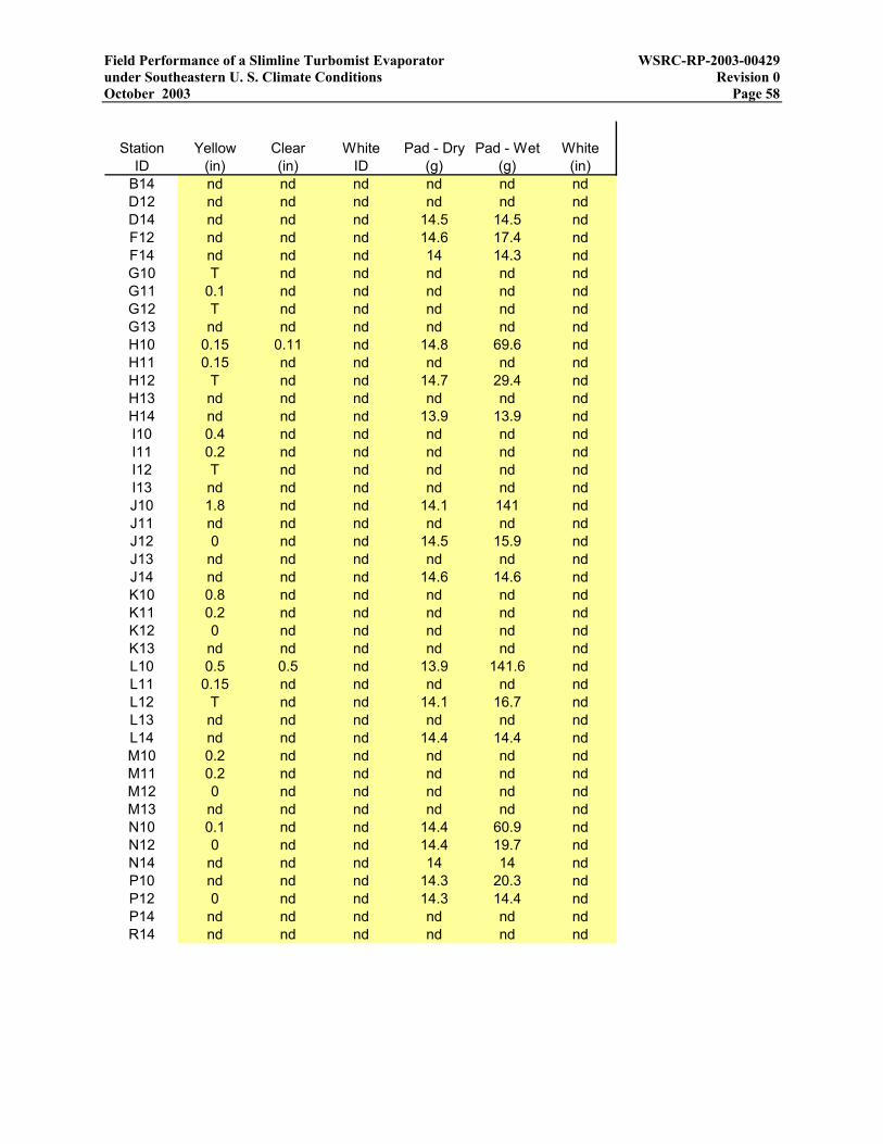
Field Performance of a Slimline Turbomist Evaporator WSRC-RP-2003-00429 under Southeastern U. S. Climate Conditions Revision 0 October 2003 Page 58
Station Yellow Clear White Pad - Dry Pad - Wet WhiteID (in) (in) ID (g) (g) (in)
B14 nd nd nd nd nd ndD12 nd nd nd nd nd ndD14 nd nd nd 14.5 14.5 ndF12 nd nd nd 14.6 17.4 ndF14 nd nd nd 14 14.3 ndG10 T nd nd nd nd ndG11 0.1 nd nd nd nd ndG12 T nd nd nd nd ndG13 nd nd nd nd nd ndH10 0.15 0.11 nd 14.8 69.6 ndH11 0.15 nd nd nd nd ndH12 T nd nd 14.7 29.4 ndH13 nd nd nd nd nd ndH14 nd nd nd 13.9 13.9 ndI10 0.4 nd nd nd nd ndI11 0.2 nd nd nd nd ndI12 T nd nd nd nd ndI13 nd nd nd nd nd ndJ10 1.8 nd nd 14.1 141 ndJ11 nd nd nd nd nd ndJ12 0 nd nd 14.5 15.9 ndJ13 nd nd nd nd nd ndJ14 nd nd nd 14.6 14.6 ndK10 0.8 nd nd nd nd ndK11 0.2 nd nd nd nd ndK12 0 nd nd nd nd ndK13 nd nd nd nd nd ndL10 0.5 0.5 nd 13.9 141.6 ndL11 0.15 nd nd nd nd ndL12 T nd nd 14.1 16.7 ndL13 nd nd nd nd nd ndL14 nd nd nd 14.4 14.4 ndM10 0.2 nd nd nd nd ndM11 0.2 nd nd nd nd ndM12 0 nd nd nd nd ndM13 nd nd nd nd nd ndN10 0.1 nd nd 14.4 60.9 ndN12 0 nd nd 14.4 19.7 ndN14 nd nd nd 14 14 ndP10 nd nd nd 14.3 20.3 ndP12 0 nd nd 14.3 14.4 ndP14 nd nd nd nd nd ndR14 nd nd nd nd nd nd