field test and evaluation report five photovoltaic … test and evaluation report five photovoltaic...
TRANSCRIPT

United States Department of Energy
Solar America Cities Program Tiger Team Report
Field Test and Evaluation Report Five Photovoltaic Power Systems
for the City of Tucson
Tucson, AZ
Andrew Rosenthal
Southwest Technology Development Institute Institute for Energy and Environment
New Mexico State University
April 14, 2008

EXECUTIVE SUMMARY Members of the DOE solar energy Tiger Team tested five municipally owned, grid connected photovoltaic (PV) power systems for the City of Tucson on March 26 and 27, 2008. The five PV systems tested were Southeast Service Center, Clements Fitness Center, and Thonydale water treatment plant systems 1, 2, and 3. During all tests, skies were virtually cloudless with only occasional, high cirrus present, and none during array testing. Southeast Service Center No performance problems were identified. There were several Code and workmanship concerns noted. These are presented in detail. Clements Fitness Center Again, no performance problems were identified, but several Code and workmanship concerns were noted. These are presented in detail. Thornydale 1, 2, 3 Thornydale systems 1 and 2 are producing output power with excessive harmonic distortion in the waveform presented to the utility. The levels of harmonics are outside the allowable range for utility connected generation equipment and must be corrected. Other Code and workmanship concerns are also detailed within this report. SOUTHEAST SERVICE CENTER The Southeast Service Center/Ward IV office is a 3,700 sq. ft. with a south-facing, flat roof. The roof-top PV system was installed in 1999. The original Omnion inverter was replaced with an SMA Sunny Boy 6000U in 2007. The array is rack-mounted facing approximately true South at a tilt of 32°. Figure 1 shows a photograph of the PV array at the Southeast Service Center.

Figure 1. PV Array at the Southeast Service Center, Tucson, AZ.
System Description
PV Module Type: ASE-300-DGF/50 PV Module Rating: 265 Wdc (at Standard Test Conditions: 1000
W/m2 irradiance, 25° C module temperature) Array Description: 24 modules, Nameplate Rating 6.36 kW dc
(STC) Array Topology: 8 modules per series string, 3 strings in parallel
(8S3P) Inverter: Sunny Boy Utility Interactive Inverter Model
6000U Visual Inspection Visual inspection of the array, BOS, inverter, and switchgear resulted in five findings of Code violations. These are as follows. A failed module in the array was replaced at some time in the past, but the replacement wiring is not properly fixed to the module frame to ensure protection from wind abrasion and mechanical strain (Figure 2). Splices have been made with tape, but that will not provide 20-year lifetime and should be covered with UV-resistant shrink tubing or other approved method.
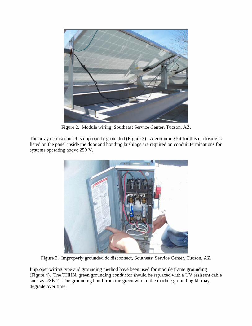
Figure 2. Module wiring, Southeast Service Center, Tucson, AZ.
The array dc disconnect is improperly grounded (Figure 3). A grounding kit for this enclosure is listed on the panel inside the door and bonding bushings are required on conduit terminations for systems operating above 250 V.
Figure 3. Improperly grounded dc disconnect, Southeast Service Center, Tucson, AZ.
Improper wiring type and grounding method have been used for module frame grounding (Figure 4). The THHN, green grounding conductor should be replaced with a UV resistant cable such as USE-2. The grounding bond from the green wire to the module grounding kit may degrade over time.

Figure 4. Improper wire type and grounding method, Southeast Service Center, Tucson, AZ.
This system was originally wired for bipolar operation with the Omnion inverter and both poles of the array were fused. In its current configuration, the negative conductor (now black) is not properly marked. The black wire should be marked with white tape to indicate it is the grounded conductor. In addition, the grounded conductor should never be fused in any string combiner boxes (Figure 5) or in the array dc disconnect box (Figure 3).
Figure 5. Improper use of fuses and ground reference, Southeast Service Center, Tucson, AZ.

Finally, because not all the ac wiring is visible or accessible, it is unclear whether the inverter output is wired on the utility (line) side of the main meter or on the customer (load) side of the meter. Required labels and placards indicating the proper connections are not installed. This should be investigated with TEP and city utility technicians. System Test Results Current-Voltage curves (IV curves) were taken of the PV array at the Southeast Service Center. A typical curve is shown in Figure 6. The IV curve was taken under clear sky conditions of 1128 W/m2 irradiance and 61.7 °C module temperature, with an array rating of 5,612 Wdc. This rating was normalized STC conditions using a linear scaling for irradiance and temperature coefficient of power of –0.47%/°C (taken from the factory data sheet). Normalized in this way, the PV array STC rating is found to be 5,817 Wdc. The IV curve shows no anomalies or the presence of weak or failed modules in the array.
Figure 6. PV Array IV Curve, Southeast Service Center, Tucson, AZ.
CLEMENTS FITNESS CENTER The Clements Fitness Center has a south-facing, flat roof with the PV array mounted on three planes of the upper and lower roof areas. The array of amorphous silicon modules is rack-mounted facing approximately true South at a tilt of 32°. Figure 7 shows a photograph of the PV array at the Clements Fitness Center. Figure 8 shows the two Xantrex inverters used by this system.

Figure 7. PV Array at the Clements Fitness Center, Tucson, AZ.
Figure 8. Two Xantrex inverters at the Clements Fitness Center, Tucson, AZ.
System Description
PV Module Type: BP Solar Millenia model MST50MVHS PV Module Rating: 50 Wdc (at Standard Test Conditions: 1000
W/m2 irradiance, 25° C module temperature) Array Description: 120 modules, Nameplate Rating 6.00 kW dc
(STC)

Array Topology: 2-independent systems, each with 60 modules all in parallel
Inverter: (2) Xantrex STXR2500 Visual Inspection Visual inspection of the array, BOS, inverter, and switchgear resulted in six findings of Code violations or areas of concern. These are as follows. An improper grounding method was used for module frame grounding throughout the array (Figure 9). Green tech screws are not rated for wet areas. In addition, the copper grounding conductor is in direct contact with aluminum module frames and steel washers resulting in rust, corrosion, and poor grounding.
Figure 9. Improper grounding method, Clements Fitness Center, Tucson, AZ.
Figure 10 shows a string combiner box with three different Code violations. The box is improperly grounded (the recommended grounding kit was not used). The black, negative conductors should have white insulation to indicate that they are ground referenced. And, an indoor-rated wire nut has been used to splice array wiring in an outdoor enclosure.

Figure 10. String combiner with three concerns, Clements Fitness Center, Tucson, AZ.
The mounting girder for the array is pulling away from the cinder block wall to which it is mounted. This must be addressed immediately to prevent collapse of the array segment.
Figure 11. Array mounting girder, Clements Fitness Center, Tucson, AZ.
Finally, though not required by Code, the array has no external (outside the inverter) dc disconnect. Having such a disconnect allows for safe (de-energized) maintenance of the system by service personnel. System Test Results

Current-Voltage curves (IV curves) were taken of both PV arrays at the Clements Fitness Center. Typical curves for each are shown in Figures 12 and 13. The IV curves were taken under clear sky conditions of approximately 1070 W/m2 irradiance and 53 °C module temperature. Summing both curves under these conditions gives an array rating of 3,952 Wdc. This rating was normalized STC conditions using a linear scaling for irradiance and temperature coefficient of power of –0.22%/°C (taken from the factory data sheet). Normalized in this way, the PV array STC rating is found to be 3,466 Wdc. The IV curves show no anomalies or the presence of weak or failed modules in the array but do show low fill factor common for modules of this type.
Figure 12. Array IV Curve, System 1, Clements Fitness Center, Tucson, AZ.

Figure 13. Array IV Curve, System 2, Clements Fitness Center, Tucson, AZ.
THORNYDALE WATER TREATMENT PLANT PV SYSTEMS 1, 2, 3 The Thornydale Reclaimed Water Treatment Plant includes a 25,000 sq. ft., flat, concrete surface on which are installed three separate PV systems, Thornydale 1, 2, and 3. Thornydale Systems 1 and 2 are identical in design. Figure 14 shows a photograph of the PV arrays at the Thornydale.
Figure 14. PV Arrays at the Thornydale Water Treatment Plant, Tucson, AZ.

System Description Thornydale Systems 1 and 2:
PV Module Type: ASE-300-DGF/50 PV Module Rating: 290 Wdc (at Standard Test Conditions: 1000
W/m2 irradiance, 25° C module temperature) Array Description: 72 modules, Nameplate Rating 20.88 kW dc
(STC) Array Topology: 9 modules per series string, 8 strings in parallel
(9S8P) Inverter: Xantrex PV2028
Thornydale 3:
PV Module Type: ASE-300-DGF/50 PV Module Rating: 300 Wdc (at Standard Test Conditions: 1000
W/m2 irradiance, 25° C module temperature) Array Description: 108 modules, Nameplate Rating 31.32 kW dc
(STC) Array Topology: 9 modules per series string, 12 strings in parallel
(9S8P) Inverter: Xantrex 30 kW
Visual Inspection Visual inspection of the array, BOS, inverter, and switchgear for the three Thornydale systems resulted in several findings of poor workmanship or Code violations. These are as follows. The wiring of Thornydale systems 1 and 2 use improper wire management. Figure 15 shows loose wires typical of those used throughout these two arrays. Loose and dangling wires are subject to fatigue and abrasion, as seen in the second half of Figure 15.
Figure 15. Loose wires showing abrasion and wear, Thornydale Water Plant, Tucson, AZ.

Figure 16 shows two problems identified throughout Thornydale Systems 1 and 2. The first is the use of plastic wire ties that will degrade over time and release their wires to flex and abrade. The second problem is that the white-painted mounting rack is not grounded. Current carrying PV conductors are in contact and can short to this ungrounded metal rack.
Figure 16. Improper use of wire ties and ungrounded metal surface in contact with current
carrying wires, Thornydale Water Plant, Tucson, AZ. Throughout Thornydale Systems 1 and 2, module wiring is improperly run into and out of metal conduit through fittings not designed for entry points in open-air locations. In contrast, Thornydale System 3 uses waterproof wire entry fittings and water-tight junction boxes.
Figure 17. Improper wire entry method on Thornydale 1 and 2 (left) and proper wire entry method on Thornydale 3 (right), Thornydale Water Plant, Tucson, AZ.

Figure 18. Shattered module in Thornydale 1 System, Thornydale Water Plant, Tucson, AZ. One shattered module was found in the Thornydale 1 system (Figure 18). This module appears to have shattered from thermal stresses and has bowed outward visibly since breaking. This particular mounting method may not be appropriate for the hot climate of Tucson. The Schott ASE module Installation, Operation, and Maintenance Manual states: A clearance of 6 mm (1/4”) between modules is sufficient in most installations to accommodate thermal expansion. However, the appropriate clearance is dependent upon many installation specific factors including the support structure, temperature at the site, and the maximum operating temperature of the module. Thornydale 3 wiring has improper markings/color codes on the grounded conductor. The grounded conductor in any PV system must be either white or marked with white tape per the NEC section 200.6 (2) – A single-conductor, sunlight-resistant, outdoor-rated cable used as a grounded conductor in photovoltaic power systems as permitted by 690.31 shall be identified at the time of installation by distinctive white marking at all terminations. White tape is suggested as a marking for these systems at all terminations for the negative conductor. In all systems, the proper, Code-required color coding and marking of grounded conductors is critical.

Figure 19. Improper color coding Thornydale 3 System, Thornydale Water Plant, Tucson, AZ. System Test Results Current-Voltage curves (IV curves) were taken of the three PV array at Thornydale. Typical curves are shown in Figures 20, 21, and 22. The IV curves were taken under clear sky conditions of approximately 1000 W/m2 irradiance and 53 °C module temperature. Ratings were normalized to STC conditions using a linear scaling for irradiance and temperature coefficient of power of –0.47%/°C (taken from the factory data sheet). Table 1 shows raw and normalized IV data for the three Thornydale systems.
Power at Measured Cond. Normalized Power (STD) Thornydale System 1
16,572 W dc (1007 W/m2 irradiance, 53 °C)
18,753 W dc
Thornydale System 2
16,804 W dc (1000 W/m2 irradiance, 53 °C)
19,015 W dc
Thornydale System 3
27,270 W dc (1121 W/m2 irradiance, 53 °C)
27,528 Wdc

Figure 20. Array IV Curve, Thornydale System 1, Water Plant, Tucson, AZ.
Figure 21. Array IV Curve, Thornydale System 2, Water Plant, Tucson, AZ.

Figure 22. Array IV Curve, Thornydale System 3, Water Plant, Tucson, AZ.
. Power quality measurements were taken of all three Xantrex inverters at Thornydale. The power being produced by the two 20 kW inverters, Thornydale 1 and 2, was found to be out of acceptable quality range in terms of voltage and current harmonics. The 30 kW inverter of system 3 was operating within allowable power quality limits. Figures 23 and 24 present waveforms for phase B current harmonics recorded from inverter 1 and inverter 3.

Figure 23. Thornydale System 1 inverter, phase B current harmonic waveform,
Thornydale Water Plant, Tucson, AZ.
Figure 24. Thornydale System 3 inverter, phase B current harmonic waveform,
Thornydale Water Plant, Tucson, AZ.

Measurements were taken under full sun with all inverters operating above 80% rated power. Inverters 1 and 2 were found to be almost identical in performance and both were well beyond the allowable current harmonic limit of 5% for injection of power onto the utility grid. Table 2 summarizes a comparison of harmonic data collected for nverter 1 and compares this with the data for inverter 3.
Table 2. Current Harmonics Summary for Thornydale System 1 and System 3 Inverters
Thornydale System 1 Thornydale System 3 Current Phase A Total Harmonic Distortion
14.67 %
4.50 %
Current Phase B Total Harmonic Distortion
15.32 %
3.12 %
Current Phase C Total Harmonic Distortion
17.93 %
5.05 %
The high levels of harmonics recorded on inverters 1 and 2 indicate that these are operating out of acceptable range for UL 1741 certification. The manufacturer (Xantrex) should be notified immediately to seek repair or adjustment to bring these two inverters back into acceptable operating specification. UL should also be notified of this condition (with unit serial numbers) as a formal report form the field.