fieldbus systems fundamentals - wayne state universityhzhang/courses/8260/lectures/chapter 1 -...
TRANSCRIPT
Fieldbus Systems Fundamentals
Hongwei Zhang
Outline
Context
History
Fieldbus characteristics
Industrial Ethernet: the new Fieldbus
Future evolution
Fieldbus: definition
IEC 61158 fieldbus standard
A fieldbus is a digital, serial, multidrop, data bus for communication with
industrial control and instrumentation devices such as – but not limited to –
transducers, actuators and local controllers
Fieldbus Foundation
A Fieldbus is a digital, two-way, multidrop communication link among
intelligent measurement and control devices. It serves as a Local Area
Network (LAN) for advanced process control, remote input/output and high
speed factory automation applications
(-) Limited in application scope; only focused on industrial sectors
Wiki Fieldbus is the name of a family of industrial computer network protocols used for real-time distributed control, standardized as IEC 61158 in 1999.
Our focus A fieldbus is simply a network used in automation, irrespective of
topology, data rates, protocols, or real- time requirements.
Broad application domains industrial process monitoring/control ground vehicles, avionics, trains building automation energy and power systems etc
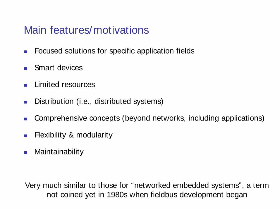
Main features/motivations
Focused solutions for specific application fields
Smart devices
Limited resources
Distribution (i.e., distributed systems)
Comprehensive concepts (beyond networks, including applications)
Flexibility & modularity
Maintainability
Very much similar to those for “networked embedded systems”, a term not coined yet in 1980s when fieldbus development began
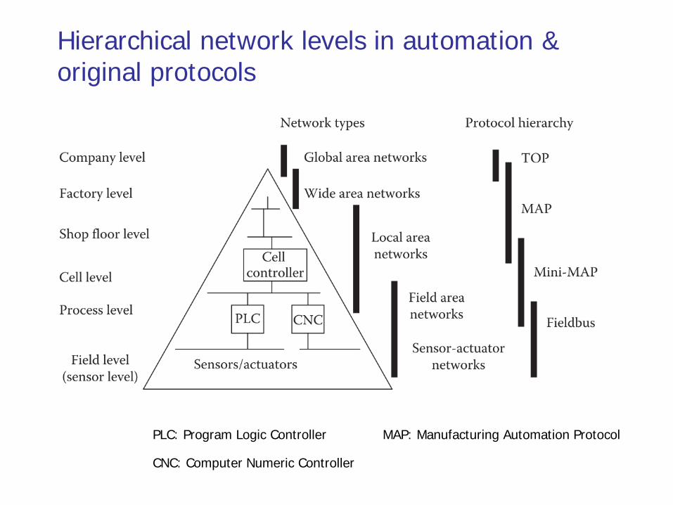
Hierarchical network levels in automation & original protocols
PLC: Program Logic Controller
CNC: Computer Numeric Controller
MAP: Manufacturing Automation Protocol
Outline
Context
History
Fieldbus characteristics
Industrial Ethernet: the new Fieldbus
Future evolution
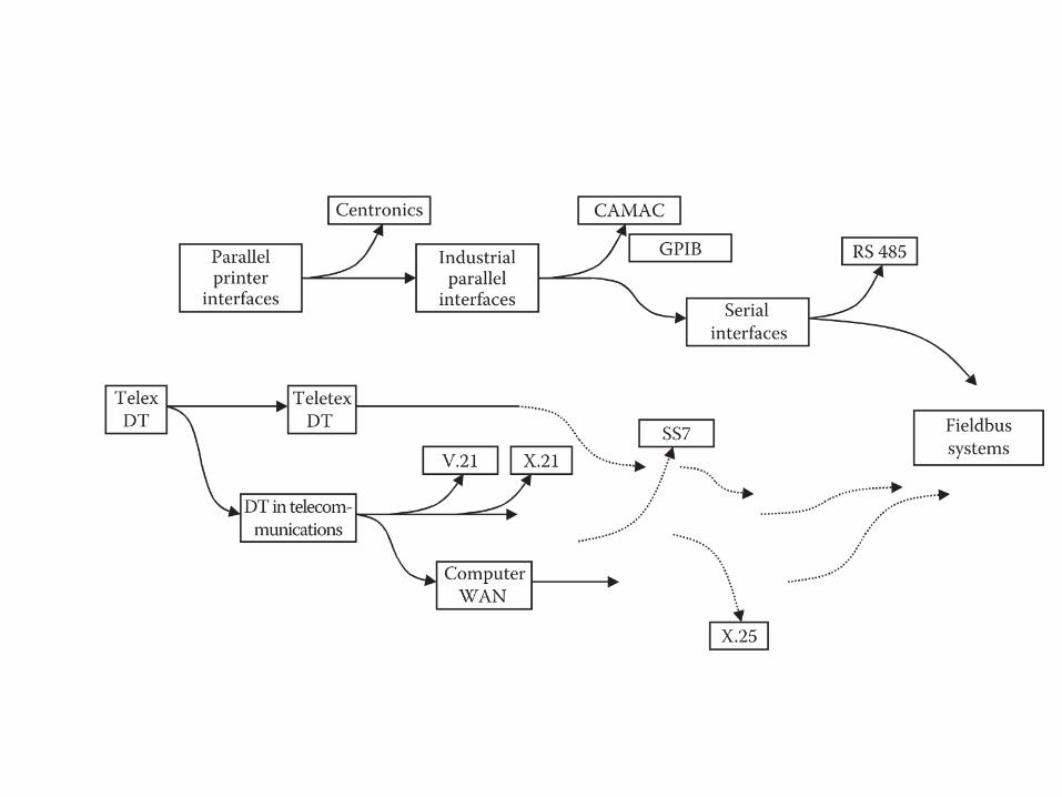
Early stages: major sources of influence
Communication engineering with large-scale telephone networks
Instrumentation and measurement systems with parallel buses and
real-time requirements
Computer science with the introduction of high-level protocol design
Evolution of fieldbuses
Different application requirements generated different solutions
A fierce selection process where not always the fittest survived, but
often those with the highest marketing power behind them
Consequently, most of the newly developed systems vanished or
remained restricted to small niches
Then, user organizations were founded to carry on the definition
and promotion of the fieldbus systems independent of individual
companies
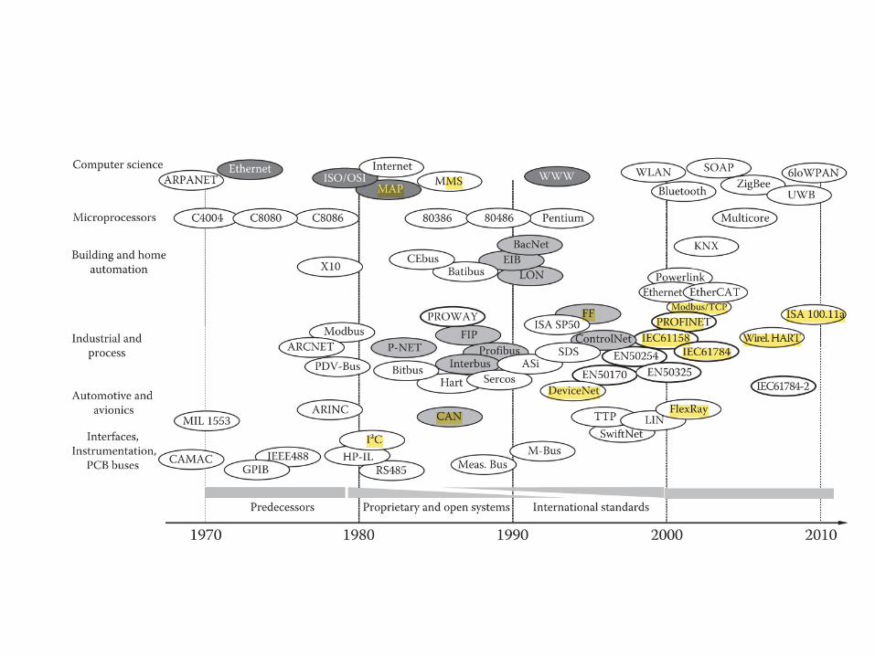
After the race for fieldbus developments, a race for standardization
was launched
National standardization relatively easy
International standardization difficult
Status quo
Factory and process automation
Multiprotocol standards IEC 61158: support 8 technologies, i.e., Foundation
Fieldbus H1, ControlNet, PROFIBUS, P-Net, FOUNDATION fieldbus HSE
(High Speed Ethernet), SwiftNet (developed for Boeing, later withdrawn),
WorldFIP, Interbus
IEC 61784-1: industrial communication networks - profiles
Standards in other domains
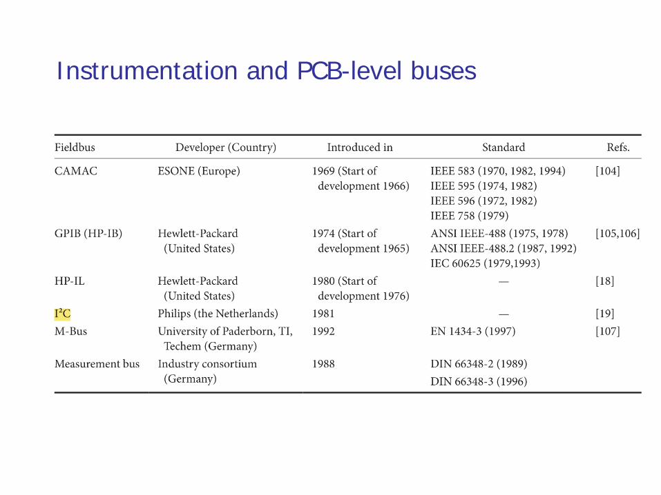
Instrumentation and PCB-level buses
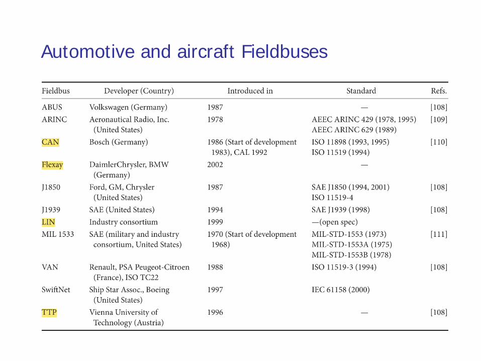
Automotive and aircraft Fieldbuses
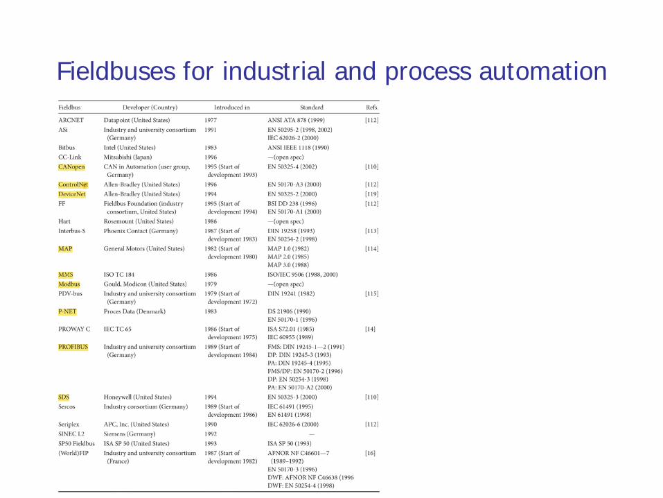
Fieldbuses for industrial and process automation
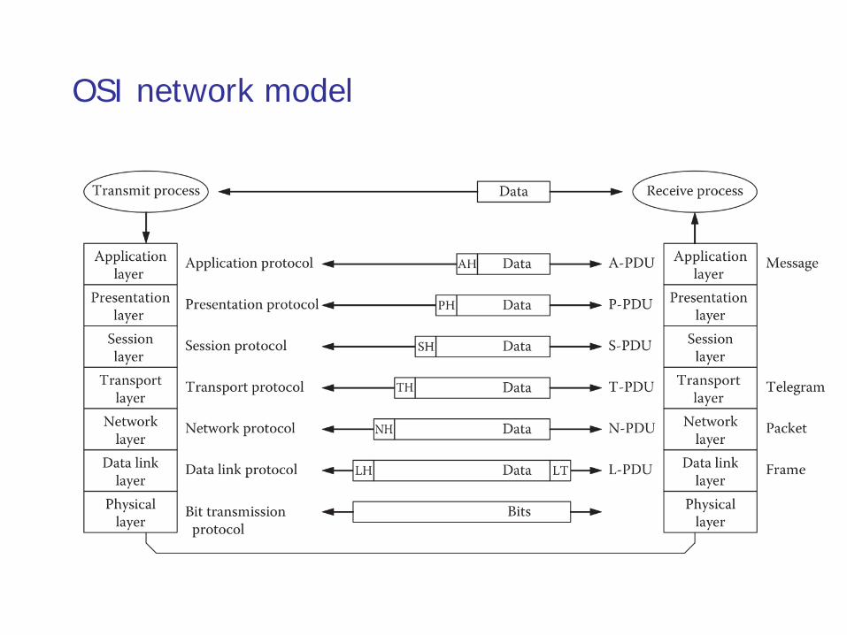
OSI network model
Outline
Context
History
Fieldbus characteristics
Industrial Ethernet: the new Fieldbus
Future evolution
Fieldbus characteristics
Just like today’s embedded system networks, fieldbus systems were
always designed for efficiency
Data transfer: messages are rather short according to the limited size of
process data that must be transmitted at a time
Protocol design and implementation: typical field devices do not provide
ample computing resources
For wireless networks, resources also constrained in power, radio bandwidth etc
Characteristic application requirements in the individual areas with
respect to real-time, topology, and economical constraints
Characteristic dimensions
Traffic characteristics and requirements
Fieldbus systems and OSI model
Network topologies
Medium access control
Communication paradigms
Fieldbus management
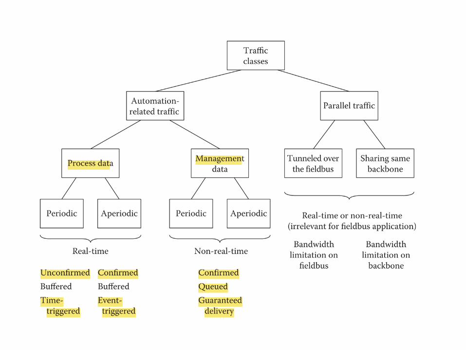
Traffic characteristics and requirements
Properties of the various data types inside a fieldbus system differ
strongly according to the processes that must be automated
Application areas like manufacturing, process, and building
automation pose different timing and consistency requirements that
are not even invariant and consistent within the application areas
Implications for Fieldbus
Data that are exchanged on a cyclic basis are usually sent via
connectionless services; most recent values matter
Acyclic data need special precautions, whether or not they are related
to process variables or management data
Data exchange paradigms
Time-triggered: specifically suited for periodic real-time data; used in many
fieldbus systems in one form or another
Event-triggered: 1) only changes in process variables are relevant for
transmission, 2) such events should be broadcasted across a network, so
that every node potentially interested in the data can receive them and
network is easily extensible
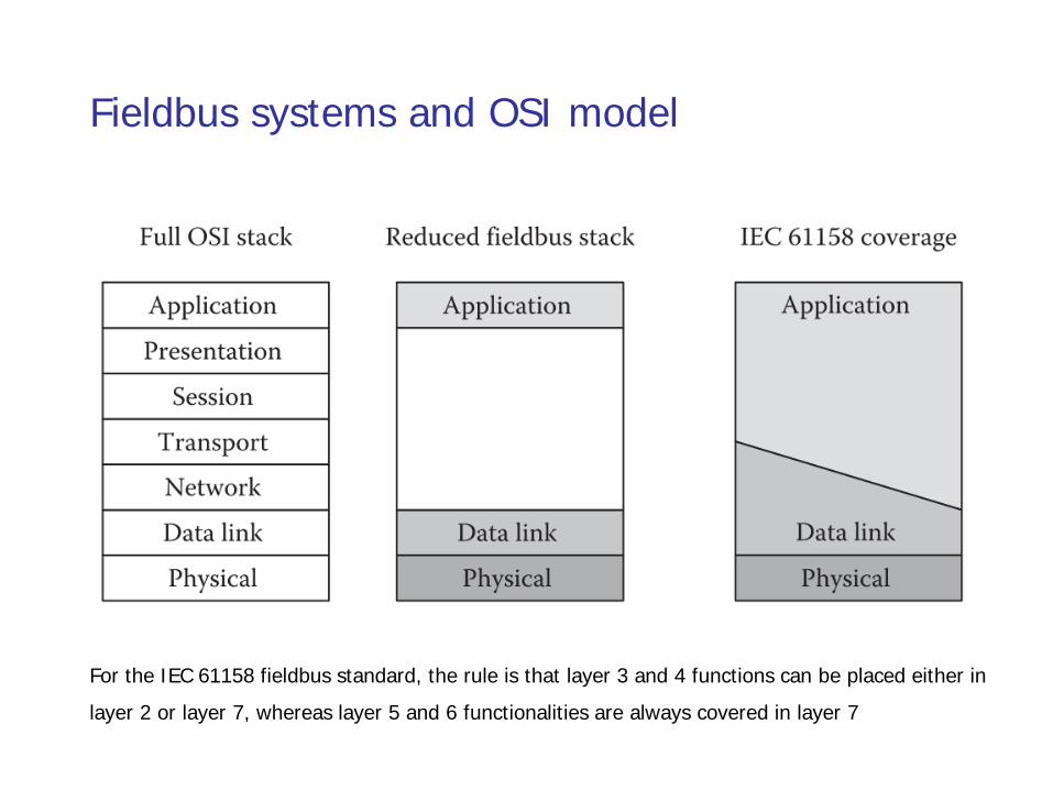
Fieldbus systems and OSI model
For the IEC 61158 fieldbus standard, the rule is that layer 3 and 4 functions can be placed either in
layer 2 or layer 7, whereas layer 5 and 6 functionalities are always covered in layer 7
Exceptions: several examples where other layers were explicitly
defined, particularly in the building automation domain with possibly
a large number of nodes
Building automation
European Installation Bus (EIB) and KNX use the network and transport
layers to implement routing and transport funcationalities
BACnet uses the network layer as well, which is especially important as
BACnet was devised as higher-layer protocol to operate on different lower-
layer protocols and links such as Ethernet, MS/TP (master–slave/token
passing), and LonTalk
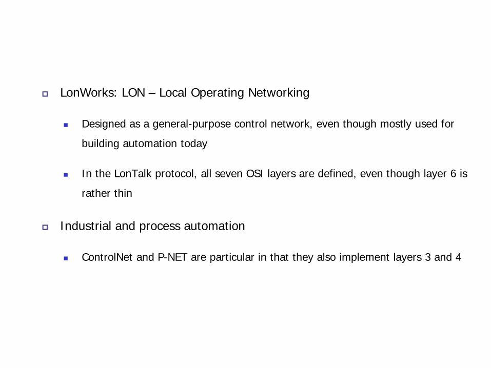
LonWorks: LON – Local Operating Networking
Designed as a general-purpose control network, even though mostly used for
building automation today
In the LonTalk protocol, all seven OSI layers are defined, even though layer 6 is
rather thin
Industrial and process automation
ControlNet and P-NET are particular in that they also implement layers 3 and 4
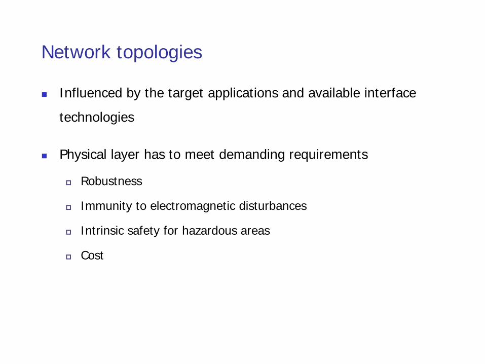
Network topologies
Influenced by the target applications and available interface
technologies
Physical layer has to meet demanding requirements
Robustness
Immunity to electromagnetic disturbances
Intrinsic safety for hazardous areas
Cost
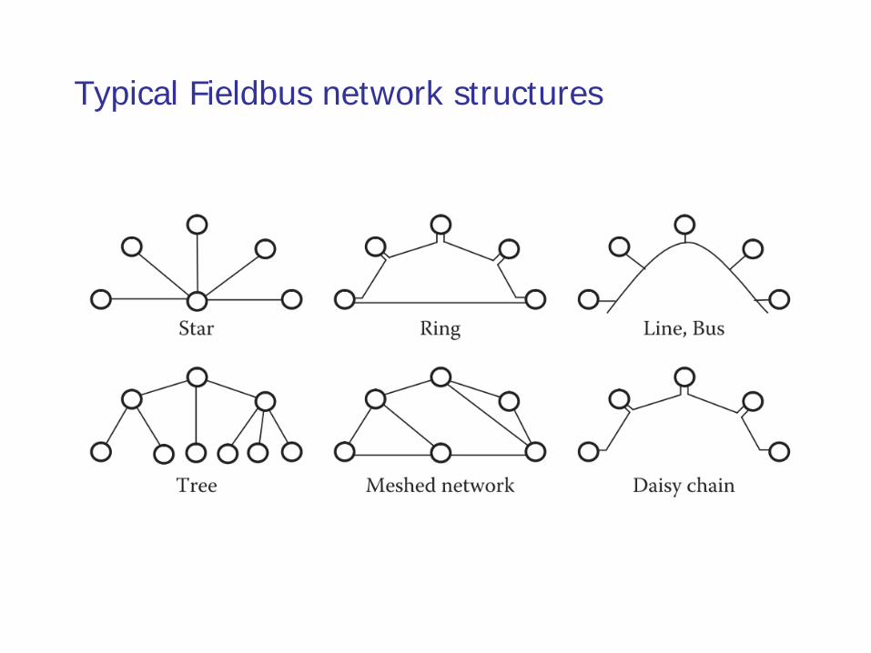
Typical Fieldbus network structures
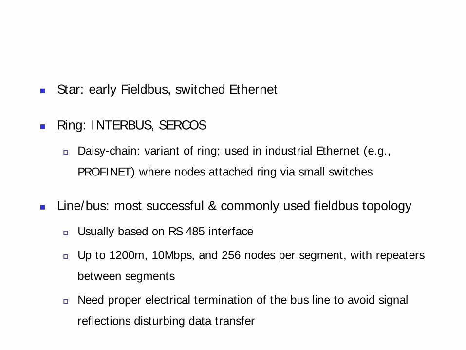
Star: early Fieldbus, switched Ethernet
Ring: INTERBUS, SERCOS
Daisy-chain: variant of ring; used in industrial Ethernet (e.g.,
PROFINET) where nodes attached ring via small switches
Line/bus: most successful & commonly used fieldbus topology
Usually based on RS 485 interface
Up to 1200m, 10Mbps, and 256 nodes per segment, with repeaters
between segments
Need proper electrical termination of the bus line to avoid signal
reflections disturbing data transfer
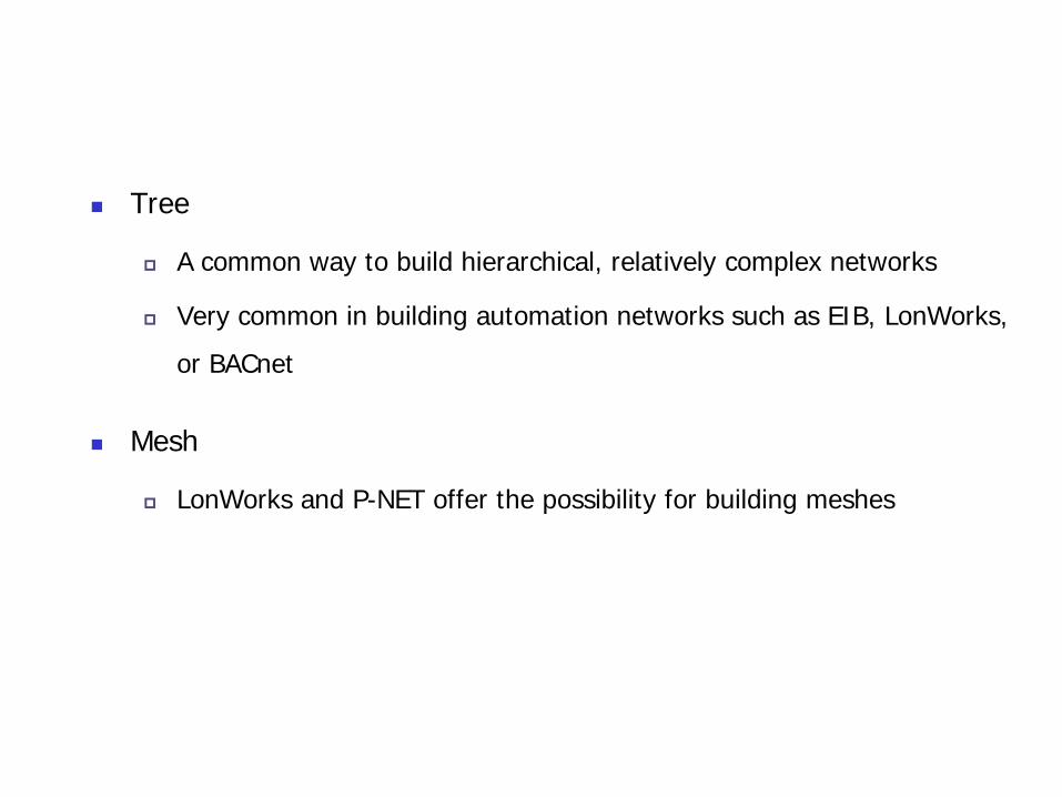
Tree
A common way to build hierarchical, relatively complex networks
Very common in building automation networks such as EIB, LonWorks,
or BACnet
Mesh
LonWorks and P-NET offer the possibility for building meshes
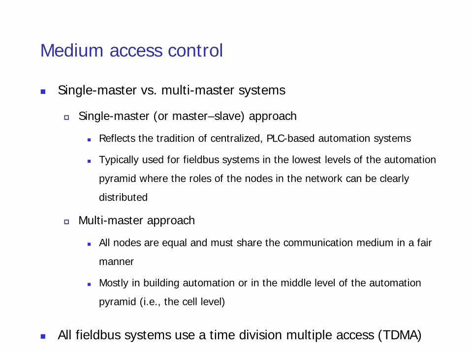
Medium access control
Single-master vs. multi-master systems
Single-master (or master–slave) approach
Reflects the tradition of centralized, PLC-based automation systems
Typically used for fieldbus systems in the lowest levels of the automation
pyramid where the roles of the nodes in the network can be clearly
distributed
Multi-master approach
All nodes are equal and must share the communication medium in a fair
manner
Mostly in building automation or in the middle level of the automation
pyramid (i.e., the cell level)
All fieldbus systems use a time division multiple access (TDMA)
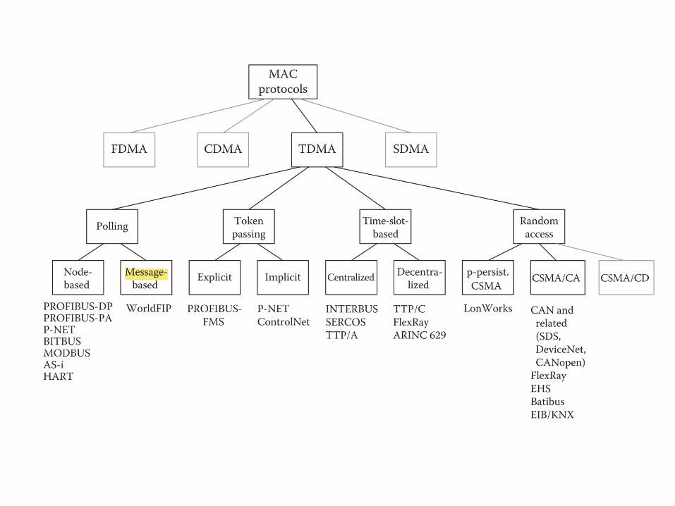
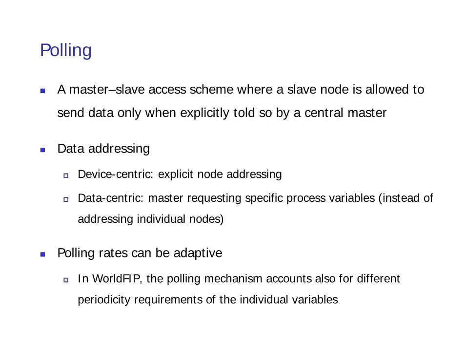
Polling
A master–slave access scheme where a slave node is allowed to
send data only when explicitly told so by a central master
Data addressing
Device-centric: explicit node addressing
Data-centric: master requesting specific process variables (instead of
addressing individual nodes)
Polling rates can be adaptive
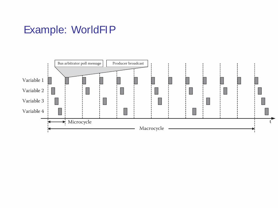
In WorldFIP, the polling mechanism accounts also for different
periodicity requirements of the individual variables
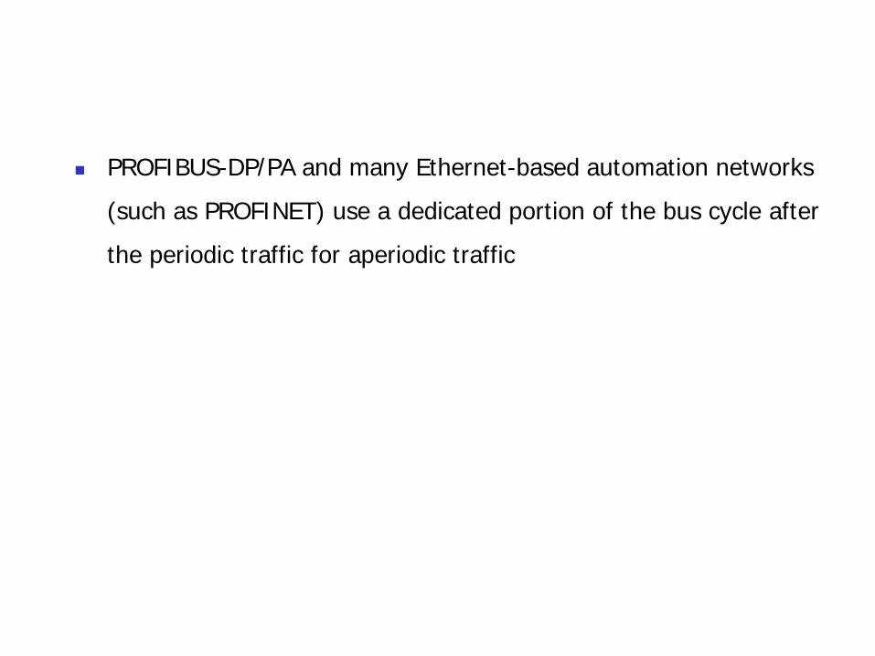
PROFIBUS-DP/PA and many Ethernet-based automation networks
(such as PROFINET) use a dedicated portion of the bus cycle after
the periodic traffic for aperiodic traffic
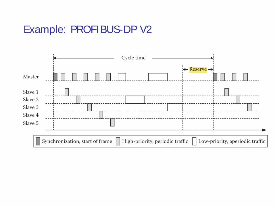
Example: PROFIBUS-DP V2
Example: WorldFIP
Toking passing (TP)
Two forms of tokens
explicitly by means of a dedicated short message
implicitly by distributed, synchronized access counters (ACs) in all nodes
Rules for ensuring
token is passed in a fair manner
errors such as lost or duplicate tokens are detected and resolved
TP is often combined with an underlying master–slave mechanism
for each node (i.e., master) to control a subset of nodes
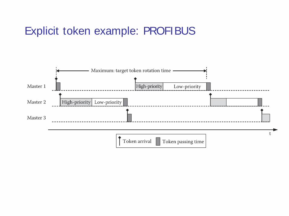
Explicit token example: PROFIBUS
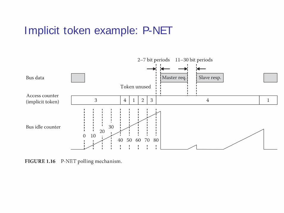
Implicit token example: P-NET
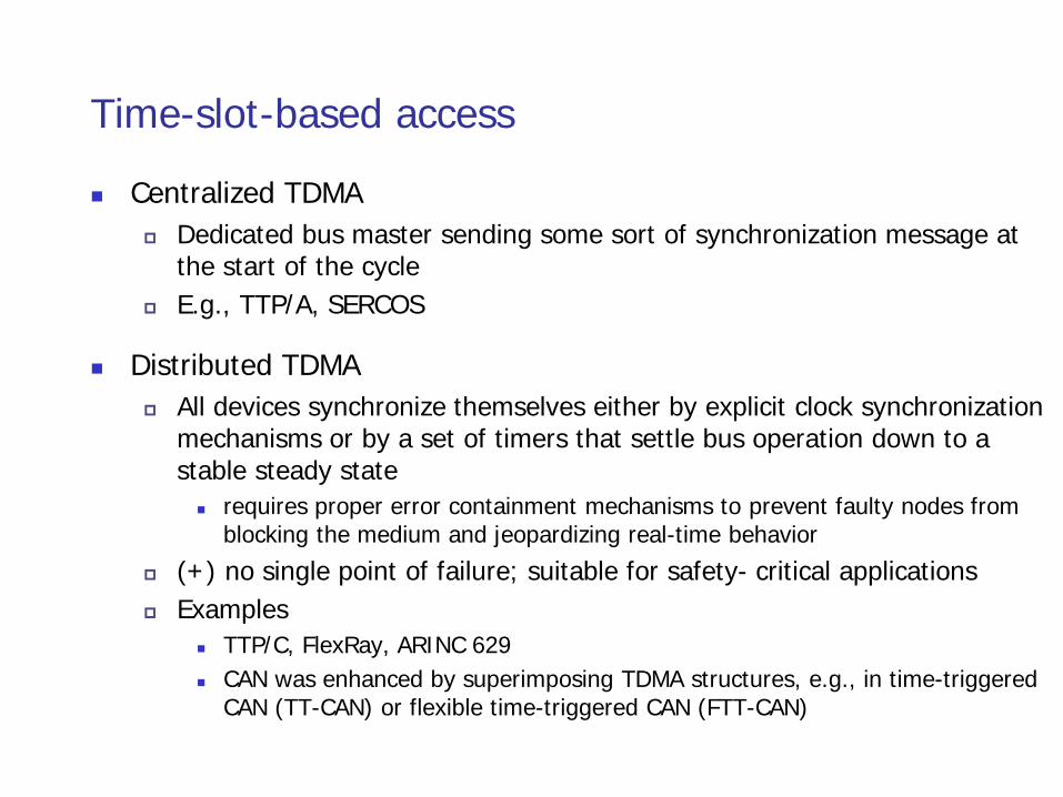
Time-slot-based access
Centralized TDMA Dedicated bus master sending some sort of synchronization message at
the start of the cycle E.g., TTP/A, SERCOS
Distributed TDMA All devices synchronize themselves either by explicit clock synchronization
mechanisms or by a set of timers that settle bus operation down to a stable steady state requires proper error containment mechanisms to prevent faulty nodes from
blocking the medium and jeopardizing real-time behavior
(+) no single point of failure; suitable for safety- critical applications Examples
TTP/C, FlexRay, ARINC 629 CAN was enhanced by superimposing TDMA structures, e.g., in time-triggered
CAN (TT-CAN) or flexible time-triggered CAN (FTT-CAN)

Centralized TDMA example: SERCOS
Random access
p-persistent CSMA (e.g., in LonWorks)
CSMA-CD (collision detection)
CSMA-CA (collision avoidance)
Sometimes called CSMA-BA (bitwise arbitration); first used in CAN (controller area network)
The bus line is designed as an open collector bus so that the low level is dominant and the high level remains recessive, that is, a “1” sent from a device can be overwritten by a “0”; CAN uses message/data-based addressing
The propagation time of the signals on the line must be short compared with the bit time to yield quasi-simultaneity for all nodes
The highest bit rate of 1Mbps => a maximum bus length of only 40m
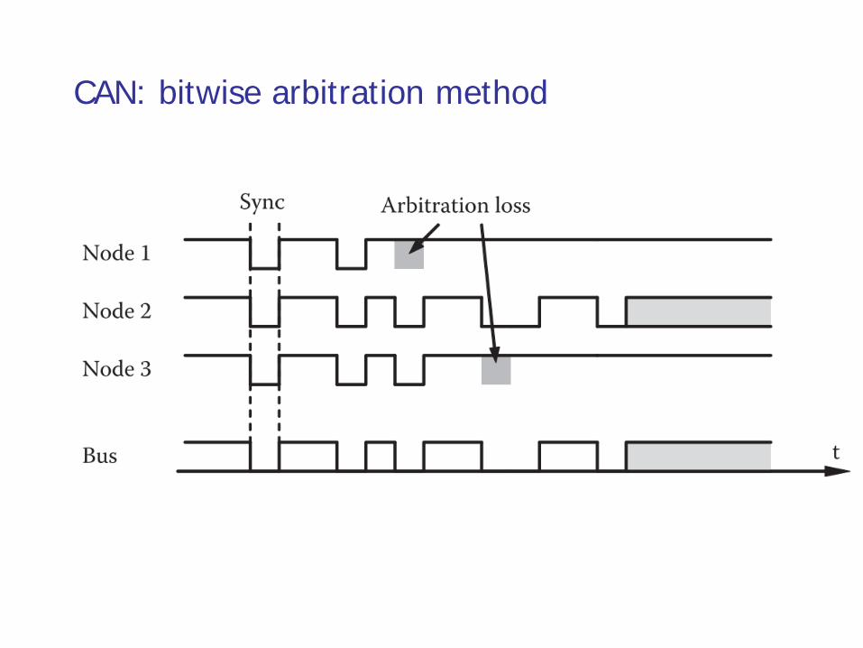
CAN: bitwise arbitration method
CSMA-BA was used in several other fieldbus systems in similar form
building automation networks such as EIB, BATIBUS, or EHS
other automotive networks such as VAN and FlexRay (for aperiodic
traffic)
CAN was also used as a basis for further extension
CAN-in-Automation user group defined the CAN application layer and
then the CANopen protocol
DeviceNet and SDS are based on CAN
CAN Kingdom protocol has been specially developed for machine controls
and safety-critical applications
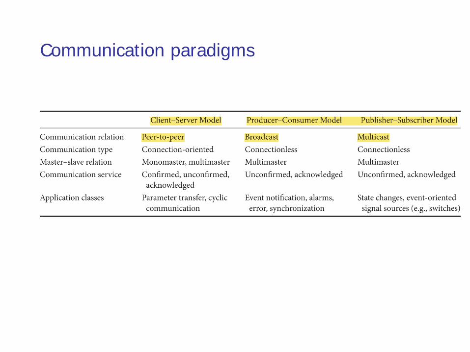
Communication paradigms
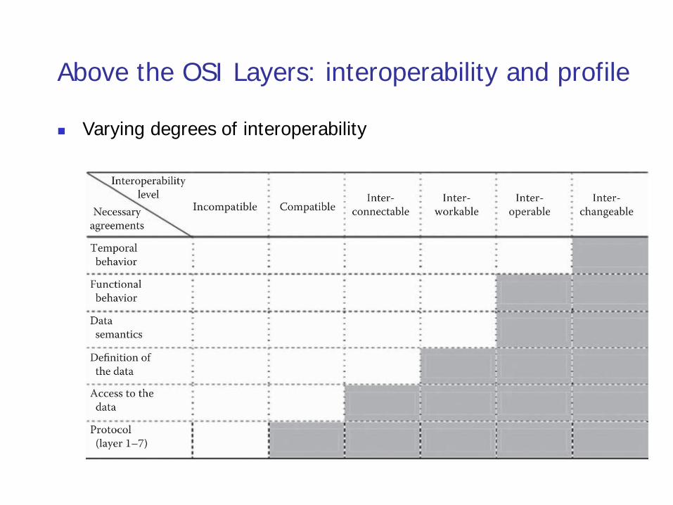
Above the OSI Layers: interoperability and profile
Varying degrees of interoperability
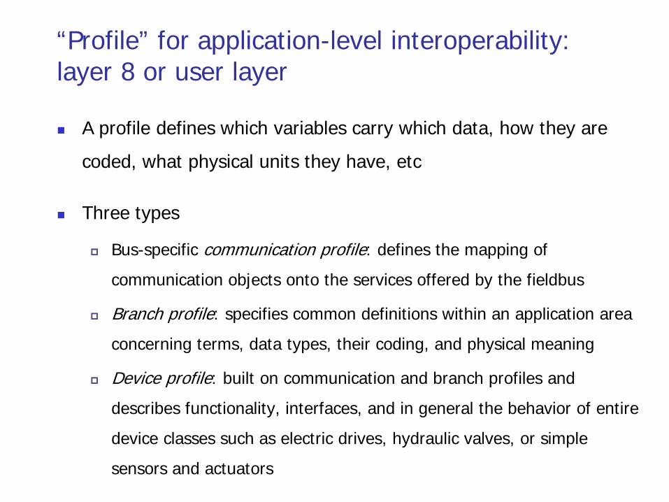
“Profile” for application-level interoperability: layer 8 or user layer
A profile defines which variables carry which data, how they are
coded, what physical units they have, etc
Three types
Bus-specific communication profile: defines the mapping of
communication objects onto the services offered by the fieldbus
Branch profile: specifies common definitions within an application area
concerning terms, data types, their coding, and physical meaning
Device profile: built on communication and branch profiles and
describes functionality, interfaces, and in general the behavior of entire
device classes such as electric drives, hydraulic valves, or simple
sensors and actuators
Fieldbus management
Proprietary, bus-specific solutions
Standard-based solutions
SNMP
XML as description language
Outline
Context
History
Fieldbus characteristics
Industrial Ethernet: the new Fieldbus
Future evolution
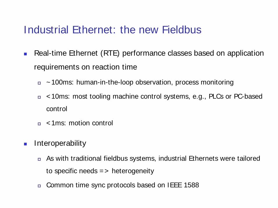
Industrial Ethernet: the new Fieldbus
Real-time Ethernet (RTE) performance classes based on application
requirements on reaction time
~100ms: human-in-the-loop observation, process monitoring
<10ms: most tooling machine control systems, e.g., PLCs or PC-based
control
<1ms: motion control
Interoperability
As with traditional fieldbus systems, industrial Ethernets were tailored
to specific needs => heterogeneity
Common time sync protocols based on IEEE 1588
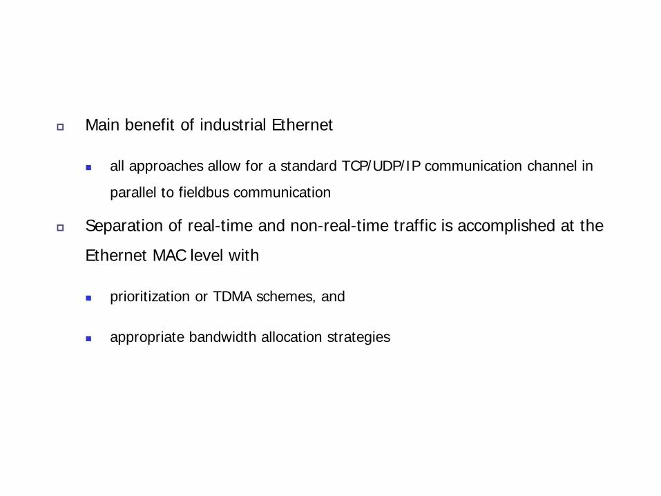
Main benefit of industrial Ethernet
all approaches allow for a standard TCP/UDP/IP communication channel in
parallel to fieldbus communication
Separation of real-time and non-real-time traffic is accomplished at the
Ethernet MAC level with
prioritization or TDMA schemes, and
appropriate bandwidth allocation strategies
Outline
Context
History
Fieldbus characteristics
Industrial Ethernet: the new Fieldbus
Future evolution
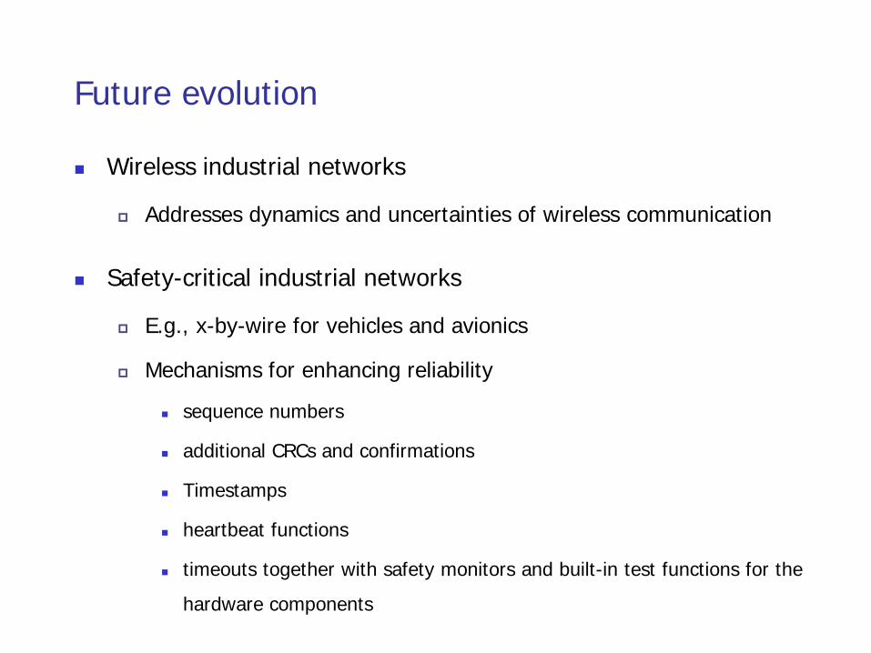
Future evolution
Wireless industrial networks
Addresses dynamics and uncertainties of wireless communication
Safety-critical industrial networks
E.g., x-by-wire for vehicles and avionics
Mechanisms for enhancing reliability
sequence numbers
additional CRCs and confirmations
Timestamps
heartbeat functions
timeouts together with safety monitors and built-in test functions for the
hardware components
Summary
Context
History
Fieldbus characteristics
Industrial Ethernet: the new Fieldbus
Future evolution