fig 33-co, p.1033. ch 33 alternating current circuits 33.1 ac sources and phasors v = v max sint =...
Post on 20-Dec-2015
217 views
TRANSCRIPT
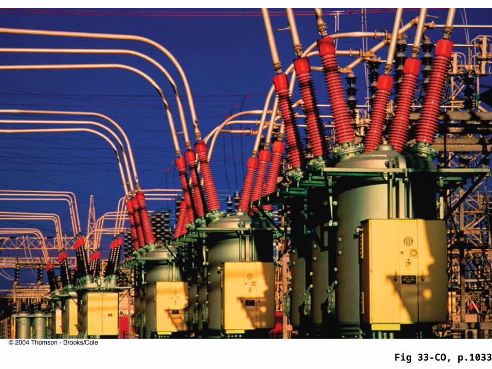
Fig 33-CO, p.1033
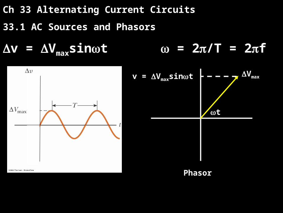
Ch 33 Alternating Current Circuits
33.1 AC Sources and Phasors
v = Vmaxsint = 2/T = 2f
t
Vmaxv = Vmaxsint
Phasor
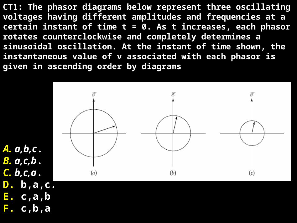
CT1: The phasor diagrams below represent three oscillating voltages having different amplitudes and frequencies at a certain instant of time t = 0. As t increases, each phasor rotates counterclockwise and completely determines a sinusoidal oscillation. At the instant of time shown, the instantaneous value of v associated with each phasor is given in ascending order by diagrams
A. a,b,c.B. a,c,b.C. b,c,a.D. b,a,c.E. c,a,bF. c,b,a
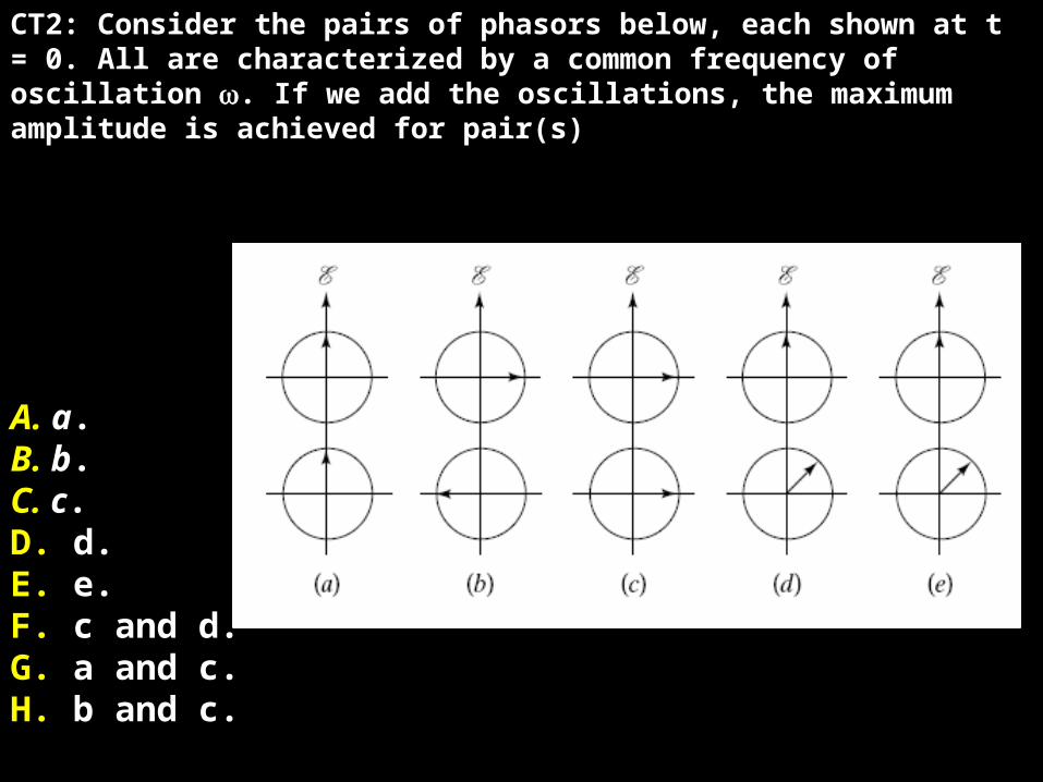
CT2: Consider the pairs of phasors below, each shown at t = 0. All are characterized by a common frequency of oscillation . If we add the oscillations, the maximum amplitude is achieved for pair(s)
A. a.B. b.C. c.D. d.E. e.F. c and d.G. a and c.H. b and c.
Ch 33 Alternating Current Circuits
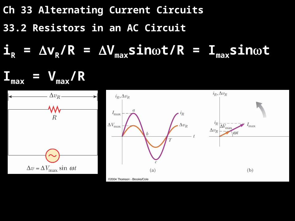
33.2 Resistors in an AC Circuit
iR = vR/R = Vmaxsint/R = Imaxsint
Imax = Vmax/R
Ch 33 Alternating Current Circuits
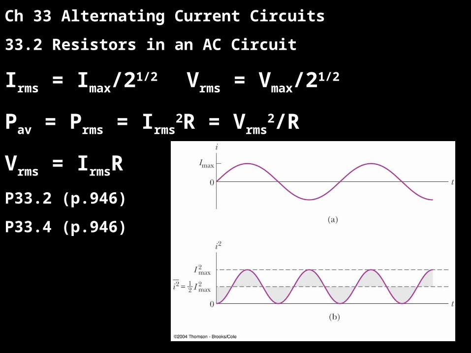
33.2 Resistors in an AC Circuit
Irms = Imax/21/2 Vrms = Vmax/21/2
Pav = Prms = Irms2R = Vrms
2/R
Vrms = IrmsR
P33.2 (p.946)
P33.4 (p.946)
Ch 33 Alternating Current Circuits
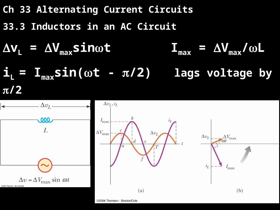
33.3 Inductors in an AC Circuit
vL = Vmaxsint Imax = Vmax/L
iL = Imaxsin(t - /2) lags voltage by /2
P33.11 (p.946) XL = L Imax = Vmax/XL
Ch 33 Alternating Current Circuits
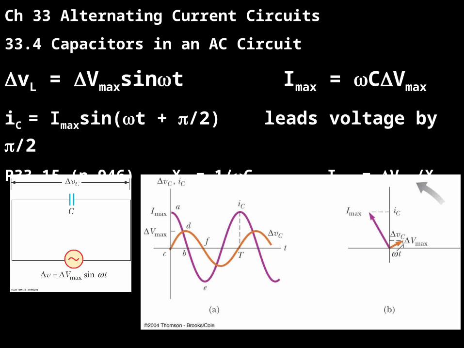
33.4 Capacitors in an AC Circuit
vL = Vmaxsint Imax = CVmax
iC = Imaxsin(t + /2) leads voltage by /2
P33.15 (p.946) XC = 1/C Imax = Vmax/XC
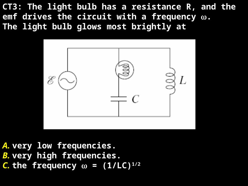
CT3: The light bulb has a resistance R, and theemf drives the circuit with a frequency .The light bulb glows most brightly at
A. very low frequencies.B. very high frequencies.C. the frequency = (1/LC)1/2
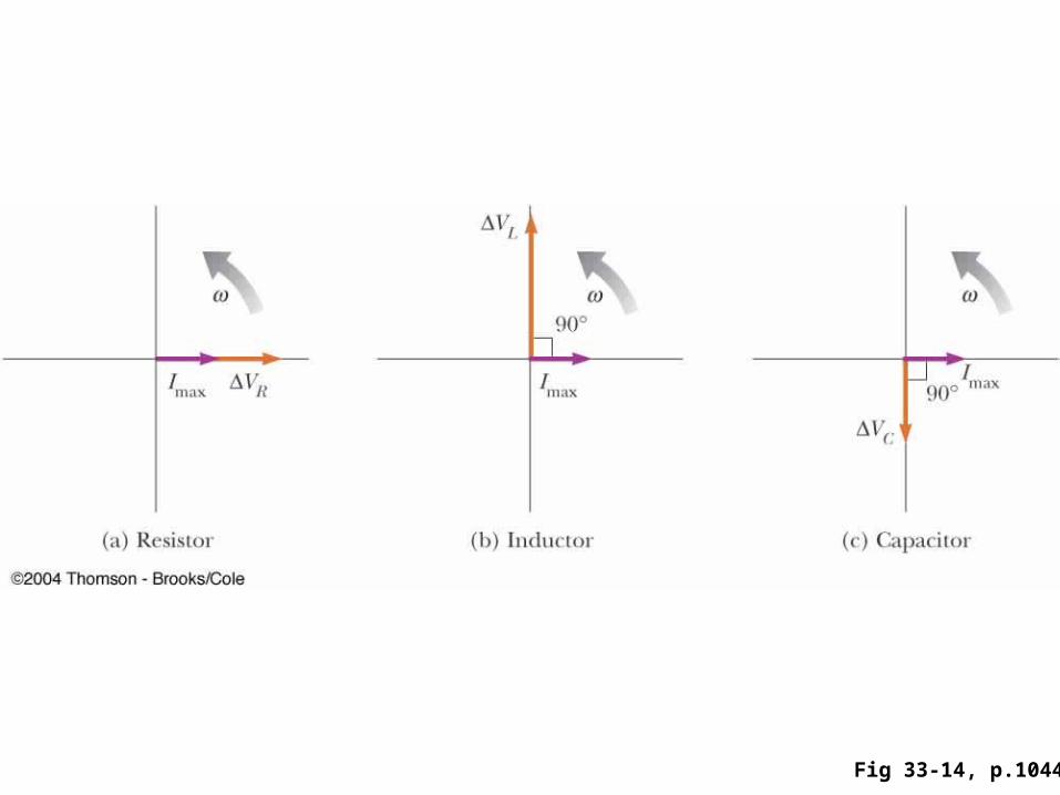
Fig 33-14, p.1044
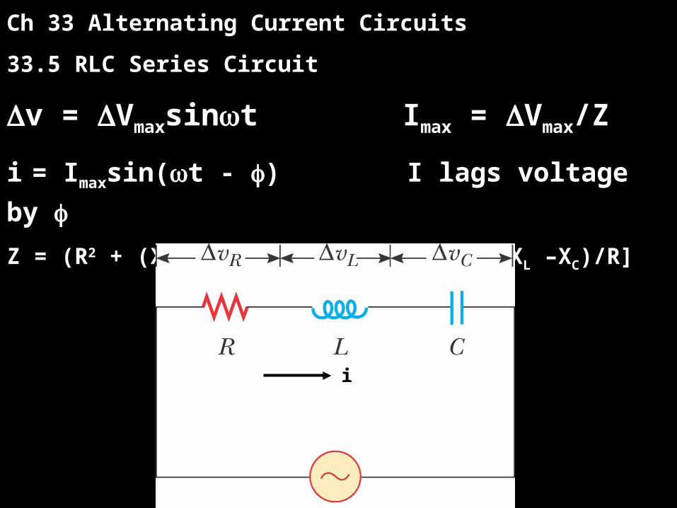
Ch 33 Alternating Current Circuits
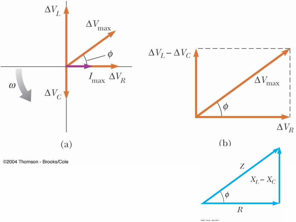
33.5 RLC Series Circuit
v = Vmaxsint Imax = Vmax/Z
i = Imaxsin(t - ) I lags voltage by
Z = (R2 + (XL – XC)2)1/2 = tan-1[(XL –XC)/R]
i
P33.17 (p.946)
P33.27 (p.947)
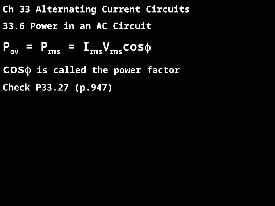
Ch 33 Alternating Current Circuits
33.6 Power in an AC Circuit
Pav = Prms = IrmsVrmscos
cos is called the power factor
Check P33.27 (p.947)
i
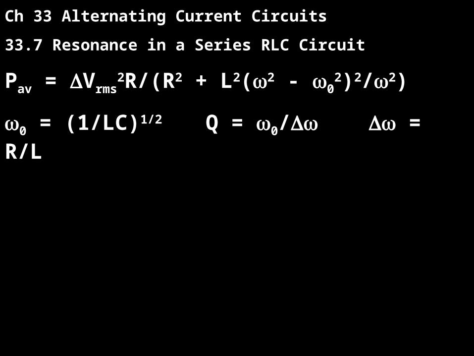
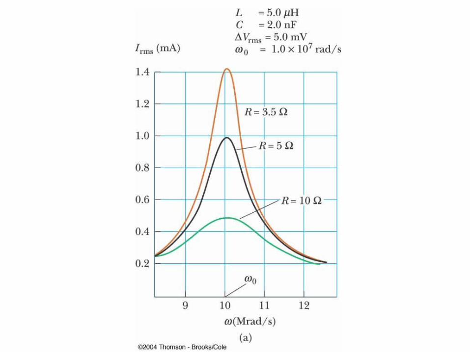
Ch 33 Alternating Current Circuits
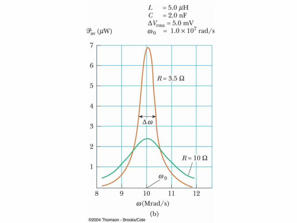
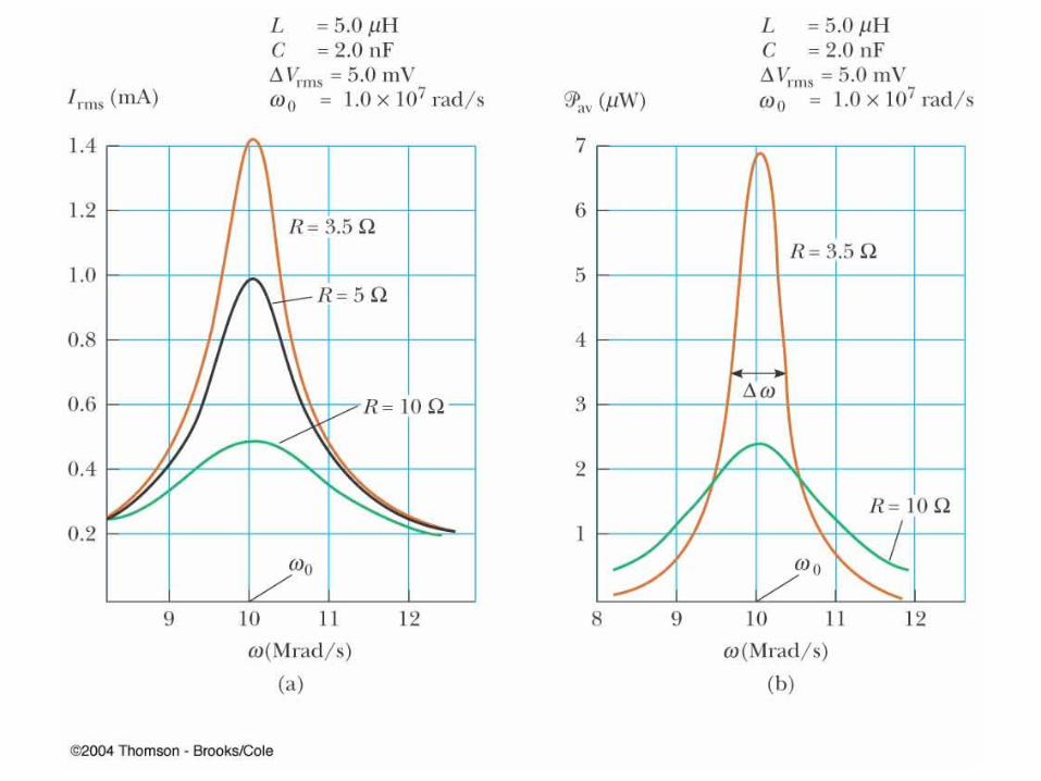
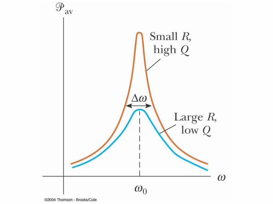
33.7 Resonance in a Series RLC Circuit
Pav = Vrms2R/(R2 + L2(2 - 0
2)2/2)
0 = (1/LC)1/2 Q = 0/ = R/L
i
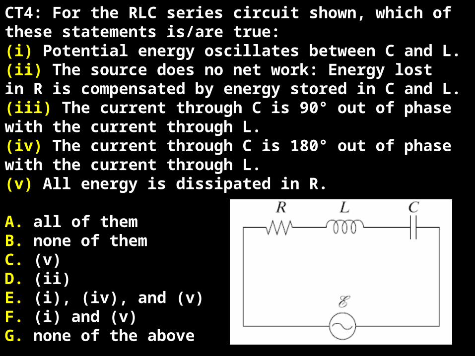
CT4: For the RLC series circuit shown, which ofthese statements is/are true:(i) Potential energy oscillates between C and L.(ii) The source does no net work: Energy lostin R is compensated by energy stored in C and L.(iii) The current through C is 90° out of phasewith the current through L.(iv) The current through C is 180° out of phasewith the current through L.(v) All energy is dissipated in R.
A. all of themB. none of themC. (v) D. (ii)E. (i), (iv), and (v)F. (i) and (v)G. none of the above
P33.38 (p.948)
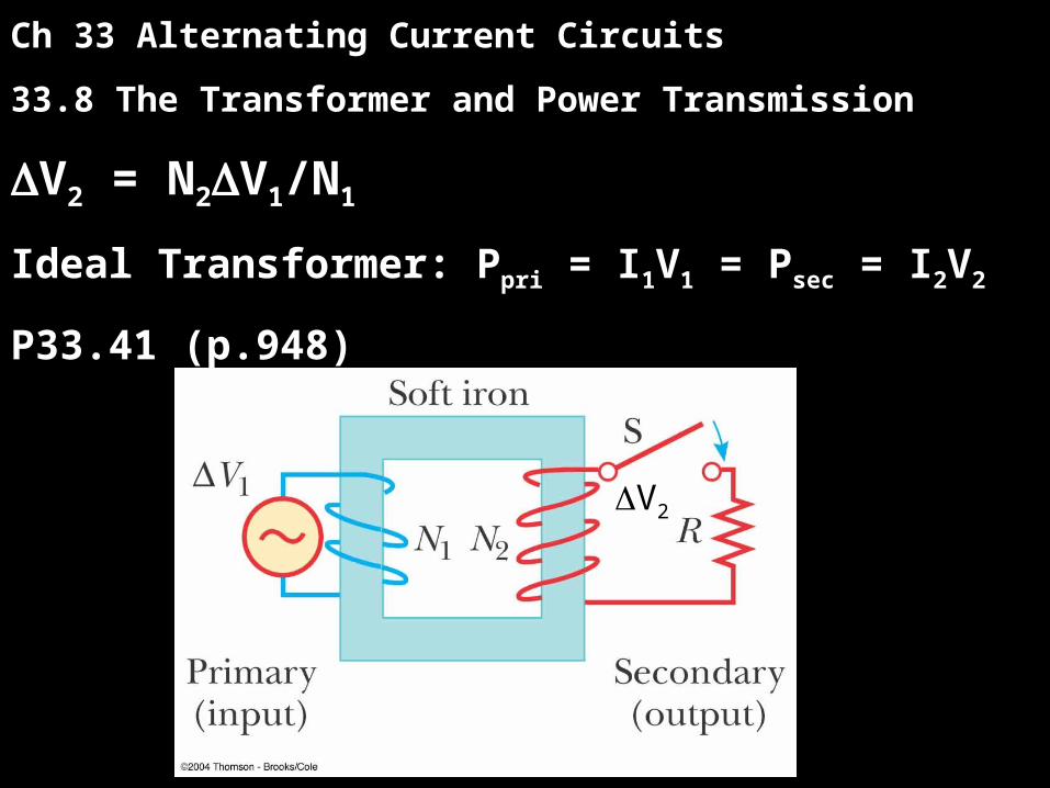
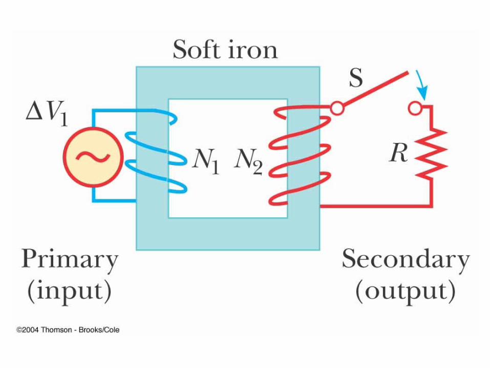
Ch 33 Alternating Current Circuits
33.8 The Transformer and Power Transmission
V2 = N2V1/N1
Ideal Transformer: Ppri = I1V1 = Psec = I2V2
P33.41 (p.948)
i
V2
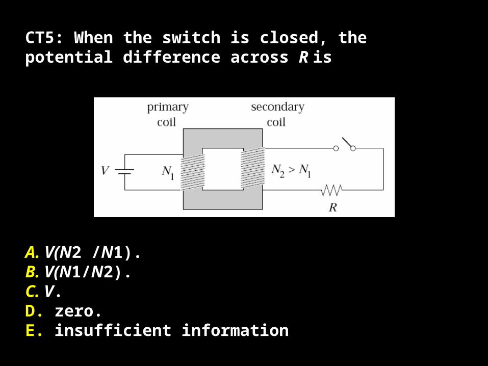
CT5: When the switch is closed, the potential difference across R is
A. V(N2 /N1).B. V(N1/N2).C. V.D. zero.E. insufficient information
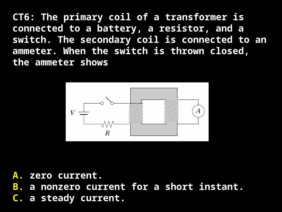
CT6: The primary coil of a transformer is connected to a battery, a resistor, and a switch. The secondary coil is connected to an ammeter. When the switch is thrown closed, the ammeter shows
A. zero current.B. a nonzero current for a short instant.C. a steady current.