figure 5-1 components of an sm chartusers.ece.utexas.edu/~roth/book/ch5_slides.pdf · figure 5-1...
TRANSCRIPT

state_name/output list
xxx
(a) state box
condition
(truebranch)
(falsebranch)1 0
conditionaloutput list
(b) decision box(c) conditional output box
optionalstate code
Figure 5-1 Components of an SM Chart

S1 / Z1 Z2
X1
Z3 Z4X3
X2Z5
n321
0 1
0 1
0 1
one state
one entrance path
linkpath a
linkpath b
n exit paths
SMblock
Figure 5-2 Example of an SM Block

S2 / S3 /
Z2
X1
X20 1
0 1
X1
Z2
S2 /
1
0
X1
Z2
S3 /
1
0
S1 / Z1
X20 1
(a) (b)
S1 / Z1
Figure 5-3 Equivalent SM Blocks
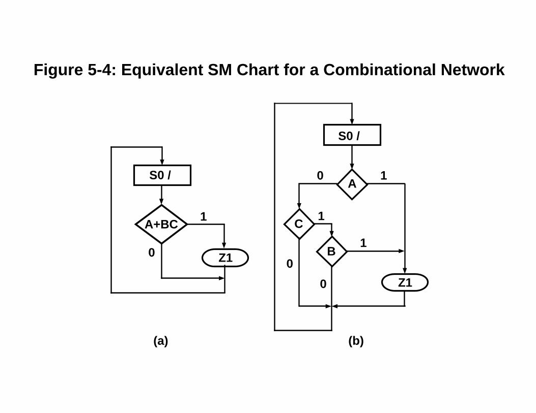
A
C
B
Z1
0
0
1
1
0 1
S0 /
A+BC
Z1
1
0
S0 /
(a) (b)
Figure 5-4: Equivalent SM Chart for a Combinational Network

0
1
S0 /
X0
1
S0 /
X
(a) incorrect (b) correct
Figure 5-5 SM Block with Feedback
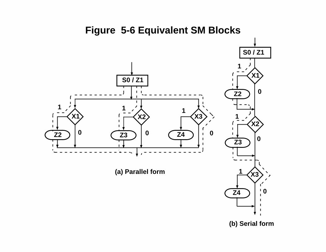
X1
Z2 0
1
X2
Z3
X3
Z4
1
0
1
0
S0 / Z1
X2 X3X1
Z2 Z3 Z4 000
1 1 1
(a) Parallel form
(b) Serial form
S0 / Z1
Figure 5-6 Equivalent SM Blocks
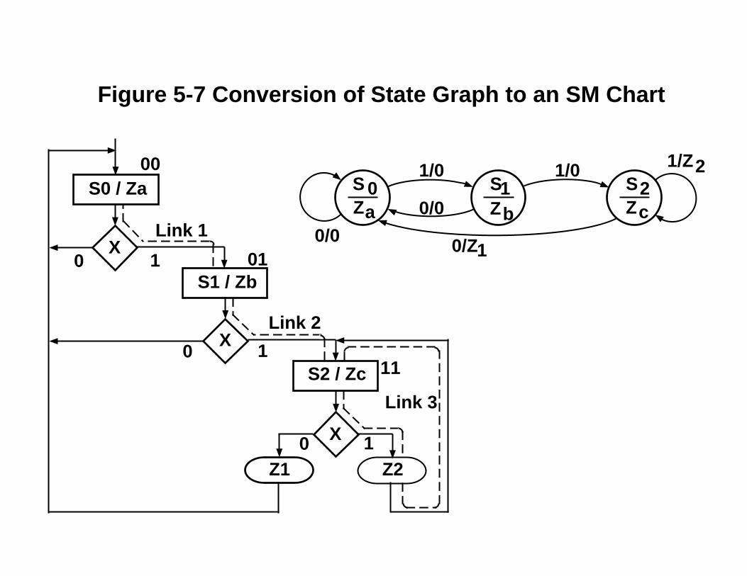
0/Z10/0
1/Z2S 0 S1 S2
1/0 1/0
0/0Za Zb ZcS0 / Za
S2 / Zc
S1 / Zb
Z1 Z2
X
10
X
X
1
1
0
0
00
01
11
Link 1
Link 2
Link 3
Figure 5-7 Conversion of State Graph to an SM Chart
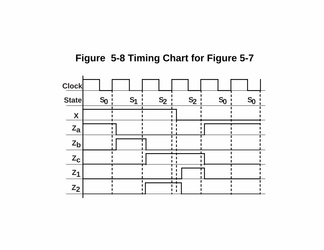
Clock
State
X
Za
Zb
Zc
Z1
Z2
S0 S1 S2 S2 S0 S0
Figure 5-8 Timing Chart for Figure 5-7

S0 /
St
Load
S1 /
M
Sh
K S2 / Sh
Ad
S3 / Done K
1
11
0
0
0
0
1
Figure 5-9 SM Chart for Binary Multiplier

Figure 5-10(a) VHDL for SM Chart of Figure 5-9entity Mult is
port(CLK,St,K,M: in bit;Load,Sh,Ad,Done: out bit);
end mult;
architecture SMbehave of Mult issignal State, Nextstate: integer range 0 to 3;
beginprocess(St, K, M, State) -- start if state or inputs changebegin
Load <= '0'; Sh <= '0'; Ad <= '0';case State is
when 0 => if St = '1' then -- St (state 0)Load <= '1'; Nextstate <= 1;
else Nextstate <= 0; -- St'end if;
when 1 => if M = '1' then -- M (state 1)Ad <= '1'; Nextstate <= 2;
else -- M'Sh <= '1'; if K = '1' then Nextstate <= 3; -- Kelse Nextstate <= 1; -- K'end if;
end if;when 2 => Sh <= '1'; -- (state 2)
if K = '1' then Nextstate <= 3; -- Kelse Nextstate <= 1; -- K'end if;
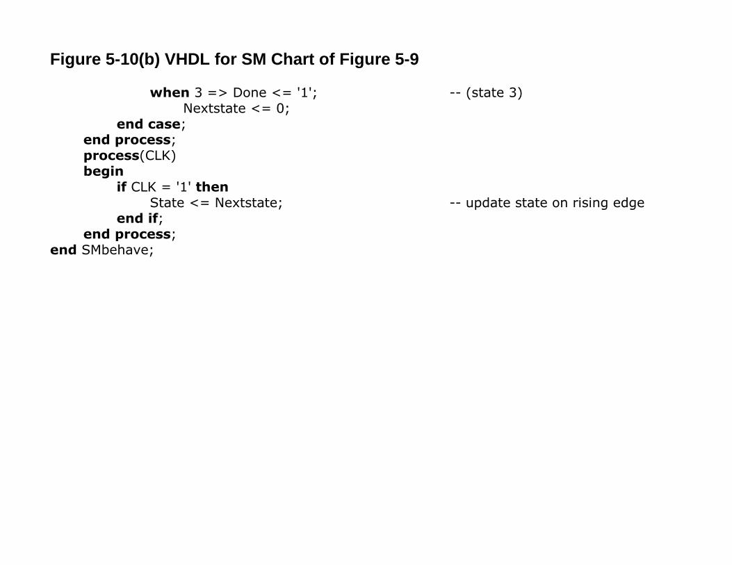
Figure 5-10(b) VHDL for SM Chart of Figure 5-9
when 3 => Done <= '1'; -- (state 3)Nextstate <= 0;
end case;end process;process(CLK)begin
if CLK = '1' thenState <= Nextstate; -- update state on rising edge
end if;end process;
end SMbehave;

Adder
Display Display
1-to-6Counter
1-to-6Counter
PointRegister
Comparator
TestLogic
Control Win
Lose
Rb
Reset
Roll
D7
D711
D2312
Eq
Sp
Sum
DiceGame Module
Figure 5-11 Block Diagram for Dice Game
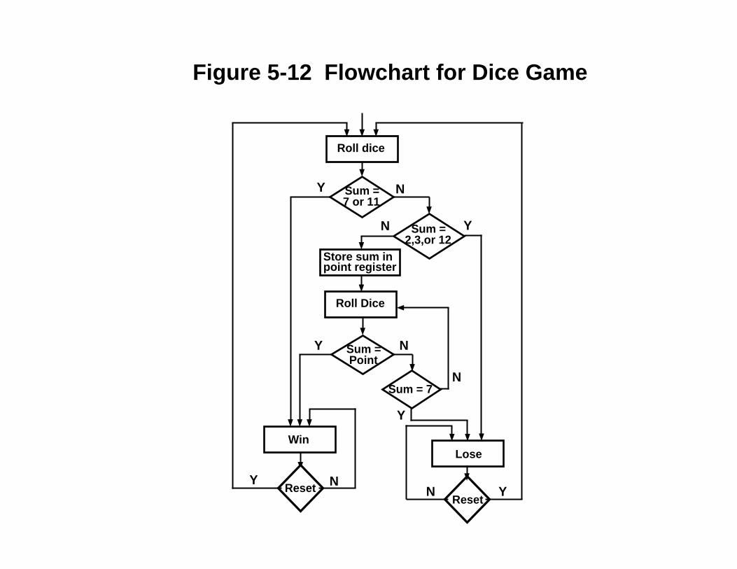
Roll dice
Sum =7 or 11
Sum =2,3,or 12
Store sum inpoint register
Roll Dice
Sum =Point
Sum = 7
Lose
ResetReset
Win
NY
N Y
NY
NYN Y
Y
N
Figure 5-12 Flowchart for Dice Game

Figure 5-13 SM Chart for Dice Game
Sp
Rb
D711
0
D2312
S1 /Roll
1
1
01
0
S0 /
Rb0
S4 /
Eq
0
1
D7
0
0
Rb
S5 /
Rb
1
1
1
0
Roll
S3 / Lose
S2 / Win
1 0Reset S3 / Lose
Reset
1
0 1
S2 / Win
S0
S4
S3S2 S1
S5
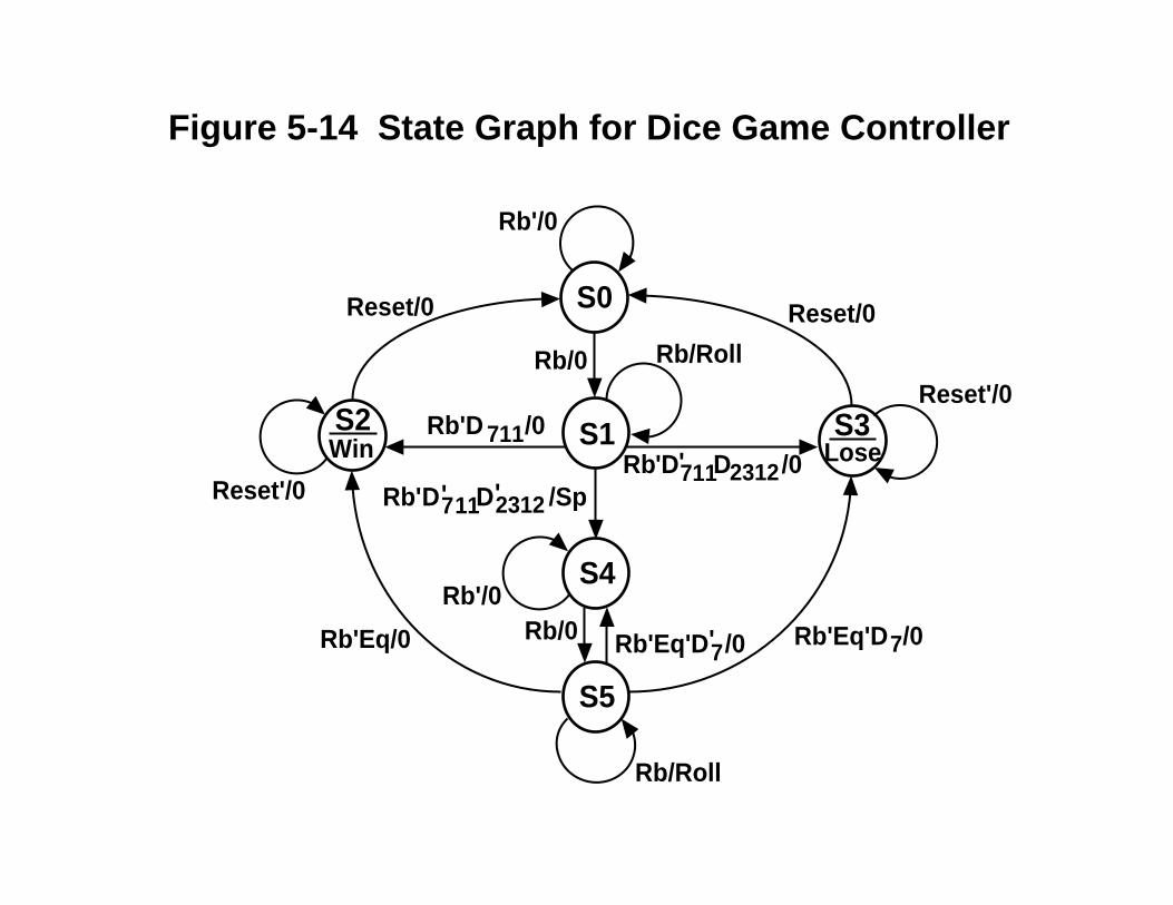
Rb'/0
Rb/0 Rb/Roll
Reset'/0
Reset'/0
Rb'D711D2312 /0
Rb'D 711/0
Rb'Eq/0 Rb'Eq'D7/0
Rb'/0
Rb'Eq'D7/0
Win Lose
Rb'D711D2312 /Sp
Rb/0
Rb/Roll
Reset/0 Reset/0
''
'
'
Figure 5-14 State Graph for Dice Game Controller

Figure 5-15(a) Behavioral Model for Dice Gameentity DiceGame is
port (Rb, Reset, CLK: in bit;Sum: in integer range 2 to 12;Roll, Win, Lose: out bit);
end DiceGame;
library BITLIB;use BITLIB.bit_pack.all;
architecture DiceBehave of DiceGame issignal State, Nextstate: integer range 0 to 5;signal Point: integer range 2 to 12;signal Sp: bit;
beginprocess(Rb, Reset, Sum, State)begin
Sp <= '0'; Roll <= '0'; Win <= '0'; Lose <= '0';case State is
when 0 => if Rb = '1' then Nextstate <= 1; end if;when 1 =>
if Rb = '1' then Roll <= '1';elsif Sum = 7 or Sum = 11 then Nextstate <= 2;elsif Sum = 2 or Sum = 3 or Sum =12 then Nextstate <= 3;else Sp <= '1'; Nextstate <= 4;
end if;when 2 => Win <= '1';
if Reset = '1' then Nextstate <= 0; end if;

Figure 5-15(b) Behavioral Model for Dice Game
when 3 => Lose <= '1';if Reset = '1' then Nextstate <= 0; end if;
when 4 => if Rb = '1' then Nextstate <= 5; end if;when 5 =>
if Rb = '1' then Roll <= '1';elsif Sum = Point then Nextstate <= 2;elsif Sum = 7 then Nextstate <= 3;else Nextstate <= 4;
end if;end case;
end process;
process(CLK)begin
if rising_edge(CLK) thenState <= Nextstate;if Sp = '1' then Point <= Sum; end if;
end if;end process;
end DiceBehave;

GameTest DiceGame
Rb
Reset
CLKSum
Roll
Win
Lose
Figure 5-16 Dice Game with Test Bench

T0 / Rb
Sum = Sumarray(i)i = i + 1
T1 /
Reset
Roll
Win orLose
0
1
0
1
T2 /
i > N T3 / (Stop)1
0
Figure 5-17 SM Chart for Dice Game Test

Figure 5-18(a) Dice Game Test Module
entity GameTest isport(Rb, Reset: out bit; Sum: out integer range 2 to 12;
CLK: inout bit; Roll, Win, Lose: in bit);end GameTest;
library BITLIB;use BITLIB.bit_pack.all;
architecture dicetest of GameTest issignal Tstate, Tnext: integer range 0 to 3;signal Trig1: bit;type arr is array(0 to 11) of integer;constant Sumarray:arr := (7,11,2,4,7,5,6,7,6,8,9,6);begin
CLK <= not CLK after 20 ns;

Figure 5-18(b) Dice Game Test Module
process(Roll, Win, Lose, Tstate)variable i: natural; -- i is initialized to 0begincase Tstate is
when 0 => Rb <= '1'; -- wait for RollReset <='0';if i>=12 then Tnext <= 3;elsif Roll = '1' then
Sum <= Sumarray(i);i:=i+1;Tnext <= 1;
end if;when 1 => Rb <= '0'; Tnext <= 2;when 2 => Tnext <= 0;
Trig1 <= not Trig1; -- toggle Trig1if (Win or Lose) = '1' then Reset <= '1'; end if;
when 3 => null; -- Stop stateend case;
end process;process(CLK)
beginif CLK = '1' then
Tstate <= Tnext;end if;
end process;end dicetest;

Figure 5-19 Tester for Dice Gameentity tester isend tester;architecture test of tester iscomponent GameTest
port(Rb, Reset: out bit;Sum: out integer range 2 to 12; CLK: inout bit; Roll, Win, Lose: in bit);
end component;component DiceGame
port (Rb, Reset, CLK: in bit; Sum: in integer range 2 to 12 ; Roll, Win, Lose: out bit);end component;signal rb1, reset1, clk1, roll1, win1, lose1: bit; signal sum1: integer range 2 to 12;begin
Dice: Dicegame port map(rb1,reset1,clk1,sum1,roll1,win1,lose1);Dicetest: GameTest port map(rb1,reset1,sum1,clk1,roll1,win1,lose1);
end test;

Figure 5-20 Simulation and Command File for Dice Game Tester
list /dicetest/ trig1 -NOTrigger sum1 win1 lose1 /dice/pointrun 2000
ns delta trig1 sum1 win1 lose1 point0 +0 0 2 0 0 2
100 +3 0 7 1 0 2260 +3 0 11 1 0 2420 +3 0 2 0 1 2580 +2 1 4 0 0 4740 +3 1 7 0 1 4900 +2 0 5 0 0 5
1060 +2 1 6 0 0 51220 +3 1 7 0 1 51380 +2 0 6 0 0 61540 +2 1 8 0 0 61700 +2 0 9 0 0 61860 +3 0 6 1 0 6

Table 5-1 PLA Table for Multiplier Control
A B St M K A+ B+ Load Sh Ad DoneS0 0 0 0 – – 0 0 0 0 0 0
0 0 1 – – 0 1 1 0 0 0S1 0 1 – 0 0 0 1 0 1 0 0
0 1 – 0 1 1 1 0 1 0 00 1 – 1 – 1 0 0 0 1 0
S2 1 0 – – 0 0 1 0 1 0 01 0 – – 1 1 1 0 1 0 0
S3 1 1 – – – 0 0 0 0 0 1
A+ = A'BM'K + A'BM + AB'K = A'B(M + K) + AB'K
B+ = A'B'St + A'BM'(K'+K) + AB'(K'+K) = A'B'St + A'BM' + AB'Sh = A'BM'(K'+K) + AB'(K'+K) = A'BM' + AB'Load = A'B'St Ad = A'B M Done = A B
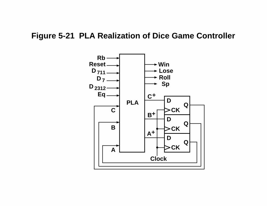
PLA
QCK
D
QCK
D
QCK
D
Clock
RbResetD 711
D 7D 2312
Eq
WinLoseRollSp
C
B
A
A+
B+
C+
Figure 5-21 PLA Realization of Dice Game Controller

Table 5-2 PLA Table for Dice Game
ABC Rb Reset D7 D711 D2312 Eq A+ B+ C+ Win Lose Roll Sp1 000 0 – – – – – 0 0 0 0 0 0 02 000 1 – – – – – 0 0 1 0 0 0 03 001 1 – – – – – 0 0 1 0 0 1 04 001 0 – – 0 0 – 1 0 0 0 0 0 15 001 0 – – 0 1 – 0 1 1 0 0 0 06 001 0 – – 1 – – 0 1 0 0 0 0 07 010 – 0 – – – – 0 1 0 1 0 0 08 010 – 1 – – – – 0 0 0 1 0 0 09 011 – 1 – – – – 0 0 0 0 1 0 010 011 – 0 – – – – 0 1 1 0 1 0 011 100 0 – – – – – 1 0 0 0 0 0 012 100 1 – – – – – 1 0 1 0 0 0 013 101 0 – 0 – – 0 1 0 0 0 0 0 014 101 0 – 1 – – 0 0 1 1 0 0 0 015 101 0 – – – – 1 0 1 0 0 0 0 016 101 1 – – – – – 1 0 1 0 0 1 017 110 – – – – – – – – – – – – –18 111 – – – – – – – – – – – – –

1
1
E1
00 01 11 10
00
01
11
10
00 01 11 10
00
01
11
10
CRb
AB
1
1 X
X
X
00 01 11 10
00
01
11
10
CRb
AB
CRb
AB
E2
1
X
X
X
X E3 E4
R'
R'
R'
R'
X
X
X
X
X
Figure 5-22 Maps Derived from Table 5-2
E1 = D'711 D'2312E2 = D'7Eq
R = ResetE3 = D'711
D'2312D711 + = D'2312D711 +
E4 = D7Eq'Eq + = D7Eq +'
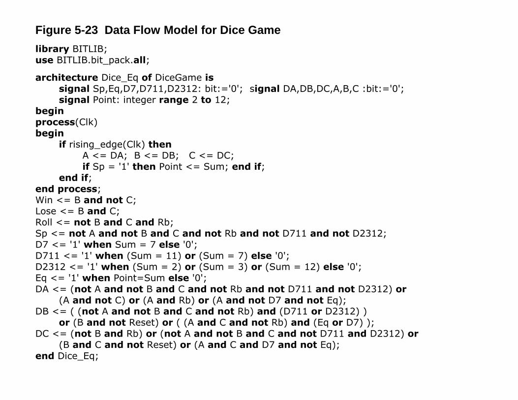
Figure 5-23 Data Flow Model for Dice Gamelibrary BITLIB;use BITLIB.bit_pack.all;
architecture Dice_Eq of DiceGame issignal Sp,Eq,D7,D711,D2312: bit:='0'; signal DA,DB,DC,A,B,C :bit:='0';signal Point: integer range 2 to 12;
beginprocess(Clk)begin
if rising_edge(Clk) thenA <= DA; B <= DB; C <= DC;if Sp = '1' then Point <= Sum; end if;
end if;end process;Win <= B and not C;Lose <= B and C;Roll <= not B and C and Rb;Sp <= not A and not B and C and not Rb and not D711 and not D2312;D7 <= '1' when Sum = 7 else '0';D711 <= '1' when (Sum = 11) or (Sum = 7) else '0';D2312 <= '1' when (Sum = 2) or (Sum = 3) or (Sum = 12) else '0';Eq <= '1' when Point=Sum else '0';DA <= (not A and not B and C and not Rb and not D711 and not D2312) or
(A and not C) or (A and Rb) or (A and not D7 and not Eq);DB <= ( (not A and not B and C and not Rb) and (D711 or D2312) )
or (B and not Reset) or ( (A and C and not Rb) and (Eq or D7) );DC <= (not B and Rb) or (not A and not B and C and not D711 and D2312) or
(B and C and not Reset) or (A and C and D7 and not Eq);end Dice_Eq;

Figure 5-24 Counter for Dice Game
entity Counter isport(Clk, Roll: in bit;
Sum: out integer range 2 to 12);end Counter;
architecture Count of Counter issignal Cnt1,Cnt2: integer range 1 to 6 := 1;begin
process (Clk)begin
if Clk='1' thenif Roll='1' then
if Cnt1=6 then Cnt1 <= 1; else Cnt1 <= Cnt1+1; end if;if Cnt1=6 then
if Cnt2=6 then Cnt2 <= 1; else Cnt2 <= Cnt2+1; end if;end if;
end if;end if;
end process; Sum <= Cnt1 + Cnt2;end Count;
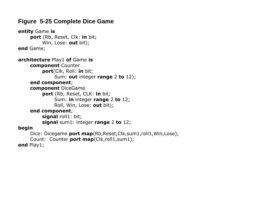
Figure 5-25 Complete Dice Game
entity Game isport (Rb, Reset, Clk: in bit;
Win, Lose: out bit);end Game;
architecture Play1 of Game iscomponent Counter
port(Clk, Roll: in bit;Sum: out integer range 2 to 12);
end component;component DiceGame
port (Rb, Reset, CLK: in bit;Sum: in integer range 2 to 12;Roll, Win, Lose: out bit);
end component;signal roll1: bit;signal sum1: integer range 2 to 12;
beginDice: Dicegame port map(Rb,Reset,Clk,sum1,roll1,Win,Lose);Count: Counter port map(Clk,roll1,sum1);
end Play1;

TEST NSF NST OUTPUT
MUXInputs
Register
PLA or ROM or PAL
MUX
...
Figure 5-26 Control Network Using an input Mux to Select the Next State

Rb
Rb 01
D711
D2312
S0 /
S1 / Roll
S11 /
S12 /S2 / Win
0
0
0
0 1
1
1
0000
0001
0010
0100 0011
Reset
1
D2312
To S3To S13
Figure 5-27(a) SM Chart with Moore Outputs and One Test per State
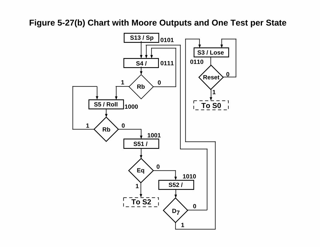
Reset
Eq
Rb
0
Rb01
D7
S13 / Sp
S3 / Lose
S4 /
S5 / Roll
S51 /
S52 /
0
0
0
1
1
1
1
0101
01100111
1000
1001
1010
To S2
To S0
Figure 5-27(b) Chart with Moore Outputs and One Test per State

01234567
MUX
RbD711
D2312
EqD7
Reset
TEST
Figure 5-28 MUX for SM Chart of Figure 5-27
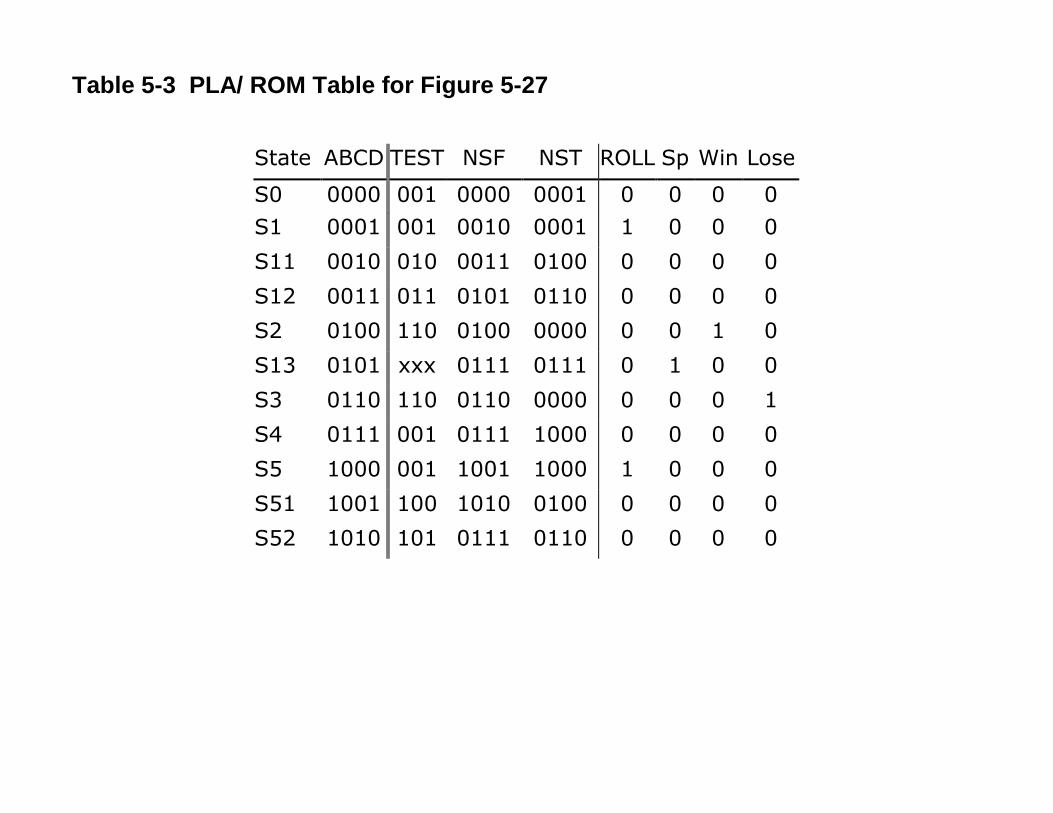
Table 5-3 PLA/ ROM Table for Figure 5-27
State ABCD TEST NSF NST ROLL Sp Win LoseS0 0000 001 0000 0001 0 0 0 0S1 0001 001 0010 0001 1 0 0 0S11 0010 010 0011 0100 0 0 0 0S12 0011 011 0101 0110 0 0 0 0S2 0100 110 0100 0000 0 0 1 0S13 0101 xxx 0111 0111 0 1 0 0S3 0110 110 0110 0000 0 0 0 1S4 0111 001 0111 1000 0 0 0 0S5 1000 001 1001 1000 1 0 0 0S51 1001 100 1010 0100 0 0 0 0S52 1010 101 0111 0110 0 0 0 0

TEST NST OUTPUT
MUXInputs
Counter
PLA or ROM or PAL
...
Data Load Count
Load/Count'
Nextstate(true)
Figure 5-29 Control Network Using a Counter for the State Register

Rb'
Rb
D711
S0 /
S1 / Roll
S11 /
S12 /S2 / Win
01
0000
0001
0010
1111 0011
0 1 1 0
1 0
0 1
1 0
Reset'D2312
To S13 To S310
Figure 5-30(a) SM chart with Serial State Assignment and Added X-states

Reset'Rb'
Rb01
Eq
D7'
S13 / Sp
S3 / Lose
S4 /
S5 / Roll
S51 /
S52 /
01
0100
10010101
0110
0111
1000
0 11 0
0 1
1 0
0 1
1 0
Sx / 1010
To S0
To S2
Figure 5-30(b) SM Chart with Serial State Assignment and Added X-state
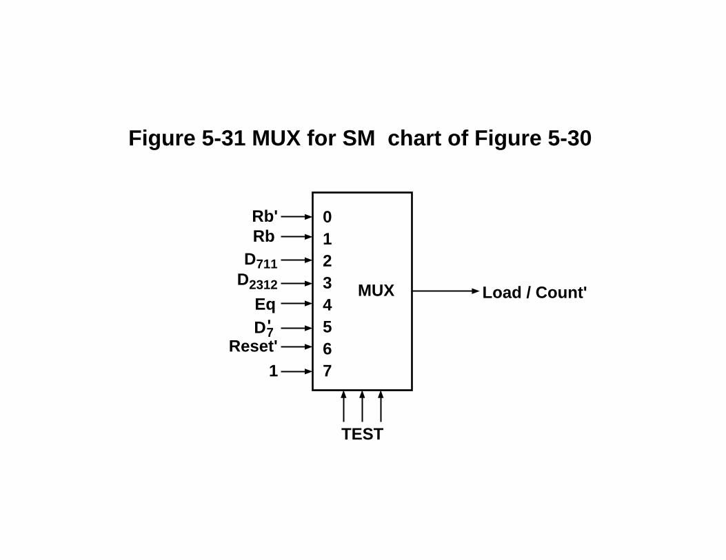
01234567
MUX
1
RbD711
D2312
Eq
TEST
Load / Count'
Rb'
Reset' D7'
Figure 5-31 MUX for SM chart of Figure 5-30
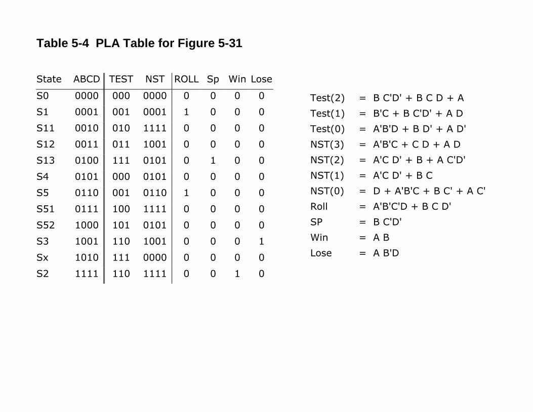
Table 5-4 PLA Table for Figure 5-31
State ABCD TEST NST ROLL Sp Win LoseS0 0000 000 0000 0 0 0 0S1 0001 001 0001 1 0 0 0S11 0010 010 1111 0 0 0 0S12 0011 011 1001 0 0 0 0S13 0100 111 0101 0 1 0 0S4 0101 000 0101 0 0 0 0S5 0110 001 0110 1 0 0 0S51 0111 100 1111 0 0 0 0S52 1000 101 0101 0 0 0 0S3 1001 110 1001 0 0 0 1Sx 1010 111 0000 0 0 0 0S2 1111 110 1111 0 0 1 0
Test(2) = B C'D' + B C D + ATest(1) = B'C + B C'D' + A DTest(0) = A'B'D + B D' + A D'NST(3) = A'B'C + C D + A DNST(2) = A'C D' + B + A C'D'NST(1) = A'C D' + B CNST(0) = D + A'B'C + B C' + A C'Roll = A'B'C'D + B C D'SP = B C'D'Win = A BLose = A B'D

SOMESTATES
SA/ZA
ZB
OTHERSTATES
IDLE
ZA
OTHERSTATES
SB/ZB
0
1
0
1
Machine A(calling machine)
Machine B(called machine)
Figure 5-32 SM Charts for Serially Linked State Machine

T1 / En_roll
1
1 T2 / Win
1
0
0
0
01
Dn_roll
Eq
D710
T2 / Win
0
1
0
1
0
0
T3 / Lose
0 1
11
Reset
1
T0 / En_roll
00
Dn_roll
D 711
D2312
Sp
Reset
ToRoll Control
FromRoll Control
ToRoll Control
FromRoll Control
Figure 5-33a Linked SM Charts for Dice Game
(a) Main control

Figure 5-33b Linked SM Charts for Dice Game
Roll
0
1
Dn_roll 0 1
0
1
S0 /
S1 /
Rb
Rb
En_roll
(b) Roll Control
FromMain Control
Main ControlTo