fiji electricity authority
TRANSCRIPT

FIJI ELECTRICITY AUTHORITY
TENDER DOCUMENTS FOR
Wailoa Mid-Life Refurbishment Control and Protection Panel Supply Contract No. MR69/2017 March 2017

MR69/2017 Wailoa Mid-Life Refurbishment Control and Protection Panel Supply
Status: For Tender Project No.: 80507610 Our ref: Tender MR69-2017_R1
Fiji Electricity Authority Wailoa Mid-Life Refurbishment MR69/2017 Control and Protection Panel Supply
CONTENTS 1 Project Background ............................................................................................................................ 1 2 Conditions of Tendering ..................................................................................................................... 2
Scope of Tender ............................................................................................................................ 2 Tender Closing Time ..................................................................................................................... 2
Tender Validity ............................................................................................................................... 2
Identification of Tenders ................................................................................................................ 2
Form of Letter of Tender ................................................................................................................ 3
Tender Documents ........................................................................................................................ 3 Information Required with Tender ................................................................................................. 3
Site Visit ......................................................................................................................................... 3
Evaluation of Tenders .................................................................................................................... 3
Acceptance of Tender .................................................................................................................... 4
Advice on Tender Outcome ........................................................................................................... 4
Tender Enquiries ........................................................................................................................... 4 Communication .............................................................................................................................. 4
Submission of Tenders .................................................................................................................. 5
Tender Conditions ......................................................................................................................... 5
Tender Responses ........................................................................................................................ 6
Confidentiality ................................................................................................................................ 7
Preferred Tenderer ........................................................................................................................ 7 Acknowledgement by Tenderer ..................................................................................................... 7
Governing Law ............................................................................................................................... 7
3 General Conditions of Contract .......................................................................................................... 8
Appendix to Tender ....................................................................................................................... 8 4 Particular Conditions of Contract ...................................................................................................... 13
Definitions .................................................................................................................................... 13 Changes and Additions to the General Conditions of Contract ................................................... 14
5 Specification – Preliminary and General .......................................................................................... 28
General ........................................................................................................................................ 28 5.1.1 Location ................................................................................................................................ 28 5.1.2 Access .................................................................................................................................. 28
5.1.3 Construction Activities to be provided by the Employer ........................................................ 28
Payments ..................................................................................................................................... 28
MR69/2017 Wailoa Mid-Life Refurbishment Control and Protection Panel Supply
Status: For Tender Project No.: 80507610 Our ref: Tender MR69-2017_R1
Programme .................................................................................................................................. 29
Tests on Completion .................................................................................................................... 30 5.4.1 Tests on Completion ............................................................................................................. 30
5.4.2 Tests after Completion .......................................................................................................... 30
5.4.3 Acceptance Certificate .......................................................................................................... 30
5.4.4 Performance Shortfall during Defects Notification Period ..................................................... 30
Delivery Procedures .................................................................................................................... 30
Manuals and As-Built Drawings ................................................................................................... 31 Documentation and Approvals ..................................................................................................... 31
Substitutions ................................................................................................................................ 31
Quality Systems and Standard Compliance ................................................................................ 31
Manufacturing Photographs ......................................................................................................... 31
Advertising ................................................................................................................................... 31 Protection of Works ..................................................................................................................... 32
6 Specification - Introduction ............................................................................................................... 33
Scope of Supply........................................................................................................................... 33 7 General Requirements...................................................................................................................... 34
Submittals .................................................................................................................................... 34
7.1.1 Design ................................................................................................................................... 34 7.1.2 Records and Instructions ...................................................................................................... 34
References, Specifications, Codes and Standards...................................................................... 34 8 Panel Descriptions ............................................................................................................................ 35
General ........................................................................................................................................ 35 Units 1&2 Main Protection Panel (2 panels in total) .................................................................... 35
Units 3&4 Main Protection Panel (2 panels in total) .................................................................... 36 Units 1-4 Backup Protection Panel (4 panels in total) ................................................................. 36
Units 1-4 Unit Control Panel 1/2 (4 panels in total) ..................................................................... 36
Units 1-4 Unit Control Panel 2/2 (4 panels in total) ..................................................................... 37
Common Services Control Panel (1 panels in total) .................................................................... 37
Intake Control Panel (1 panels in total) ....................................................................................... 38
Sundry Requirements .................................................................................................................. 38 Factory Inspection and Testing .................................................................................................... 39
Installation, Testing and Commissioning ..................................................................................... 39
Spare Parts .................................................................................................................................. 39
8.12.1 Specified Spare Parts ........................................................................................................... 39 8.12.2 Optional Spare Parts............................................................................................................. 39
Panel Data ................................................................................................................................... 39 9 Relay and PLC Order Codes ............................................................................................................ 40
SEL Protective Relays and other components ............................................................................ 40 Schneider PLCs ........................................................................................................................... 40
MR69/2017 Wailoa Mid-Life Refurbishment Control and Protection Panel Supply
Status: For Tender Project No.: 80507610 Our ref: Tender MR69-2017_R1
9.2.1 Units 1-4 Unit Control Panels (4 panel suites) ...................................................................... 40 9.2.2 Station Common Services Control Panel .............................................................................. 42
9.2.2.1 Intake Services Control Panel ....................................................................................... 42 Schedule 1 – Tender Forms ................................................................................................................. 44
Tender Form 1 – Letter of Tender ...................................................................................................... 45 Tender Form 2 – Tender Price and Price Breakdown ....................................................................... 47
Tender Form 3 – Equipment Data ...................................................................................................... 49
Tender Form 4 – Proposed Suppliers and Sub-Contractors ........................................................... 52 Tender Form 5 – Percentage On-Costs ............................................................................................. 53
Tender Form 6 – Statement of Conformance .................................................................................... 54
Schedule 2 – Form of Contract Agreement ........................................................................................ 55
Appendix A Employers Drawings .................................................................................................... 57
Appendix B Common Requirements Specification .......................................................................... 58

MR69/2017 Wailoa Mid-Life Refurbishment Control and Protection Panel Supply
Status: For Tender Project No.: 80507610 Our ref: Tender MR69-2017_R1

Status – For Tender Page 1 October 2016 Project Number – 80508617 Tender MR69-2017_R1
1 Project Background
Wailoa Power Station is four unit station capable of generating 78.3MW, while the individual units operating on their own could originally produce up to 21.3MW at rated flow and maximum reservoir level. The station was finally commissioned in 1983.
The existing control and protection equipment installed at Wailoa Power Station is some 30 years old and is now redundant.
This Contract is for the design, manufacture, factory test and deliver to Site of replacement control and protection panel assemblies.
Other contracts associated with the turbine generators will be proceeding in conjunction with this Contract. The Contractor is required to cooperate with the Employer and other contractors to help facilitate the smooth execution of the work.
The other contracts include:- • Refurbishment of the four existing generators. • Refurbishment of the four existing turbines and governors. • Replacement of the excitation system. • Replacement of the turbine inlet valves. • Replacement of the tail race coolers and upgrade of the cooling water system. • Provision of control system software. • Provision of penstock flow monitoring systems. • Numerous small works on the station.
A number of other refurbishment projects have already been undertaken at the station including:- • Replacement of the main 11/132kV step up transformers (completed 2013). • Replacement of the electronic governors (completed 2012). • Provision of a single new turbine inlet valve and provision of new hydraulic system to enable
refurbishment of the existing valves (contract let 2015);

MR69/2017 Wailoa Mid-Life Refurbishment Control and Protection Panel Supply
Status – For Tender Page 2 March 2017 Project Number – 80508617 Tender MR69-2017_R1
2 Conditions of Tendering
Scope of Tender The Fiji Electricity Authority (FEA) invites Tenders for the design, manufacture, factory testing and delivery to site of control and protection panels for the Wailoa hydro power facility.
The General Conditions of Contract pursuant to which the Contractor will provide the Works are based on FIDIC Conditions of Contract for Plant and Design Build for Electrical and Mechanical Plant and for Building and Engineering Works Designed by the Contractor, First Edition, 1999.
These Instructions comprise these instructions to tenderers together with all documents issued to tenderers in respect of the Works.
These Instructions do not constitute an offer, but are merely an invitation to the tenderer to submit a Tender.
All documents supplied by FEA remain the property of FEA. FEA reserves the right to request the immediate return of all documents supplied and any copies made of them at any time.
Tender Closing Time
Tenders shall be submitted to the TENDER LINK Electronic Tender Box https://www.tenderlink.com/fea no later than 4:00pm, on 26 April 2017.
In addition hard copies of the tender, one original and one copy, must be deposited in the tender box located at the FEA Head Office, 2 Marlow Street, Suva, Fiji no later than 4:00pm, on Monday, 1st May, 2017. Addressed as”
Tender – MR 69/2017 – Wailoa Control and Protection Panel Tender.
The Secretary Tender Committee
Fiji Electricity Authority
Head Office
Suva
Fiji
Evidence must be included demonstrating that the hard copy was dispatched from the Tenderers premises prior to the tenderlink closing date and time.
For further information contact The Secretary Tender Committee, by e-mail [email protected]
Tender Validity All Tenders shall remain open and valid for acceptance for a period of 60 days after the Tender Closing Time.
A Tender, once submitted, may only be varied by the tenderer with the prior written consent of FEA.
Identification of Tenders Tender documents are to be delivered packaged and clearly identified.

MR69/2017 Wailoa Mid-Life Refurbishment Control and Protection Panel Supply
Status – For Tender Page 3 March 2017 Project Number – 80508617 Tender MR69-2017_R1
Form of Letter of Tender The form of Letter of Tender shall be as set out in Schedule 1, Tender Form 1.
Tender Documents The tender documents comprise the following:
a) Part 1 – Background to the Contract b) Part 2 – Tender Conditions c) Part 3 - General Conditions of Contract d) Part 4 - Particular Conditions of Contract e) Parts 5, 6, 7, 8, 9 – Specification f) Tender Schedules
Information Required with Tender Tenders shall include the name of the tenderer and a complete postal address for service of notices. Tenders shall include the following minimum information for evaluation:
• Fixed, lump sum tender price. All prices must be quoted in a single currency, nominated by the contractor plus Fijian dollars if required. The prices should excluding Fiji VAT and Withholding Tax and shall be deemed to include all direct, indirect and ancillary charges and costs for the Works;
• Statement of compliance with all Tender and Contract requirements.
• Completed tender forms;
• Proposed programme for design, fabrication and delivery;
• Any supplementary information required by the documents issued to the tenderers;
• Any interpretation or other statements by the tenderer affecting the Tender;
• The Tender shall be signed by or on behalf of the tenderer by a person with the delegated authority to do so. Written proof of the delegated authority to sign the tender offer may be requested.
Site Visit A site visit is not considered necessary for this Tender.
Evaluation of Tenders Tenders received will be evaluated on the basis of such matters as FEA in its sole discretion determines are relevant, which may include the following:
• Quality of the solutions and plant offered and completeness of the offer.
• Tender sum and quoted rates and on-costs for possible approved variations.
• Proposed programme for the implementation and completion of the Works.
• Tenderer's experience, capability and commitment to achieving the project objectives.
• Tenderer's health and safety performance record and commitment.
• Compliance with the Contract conditions and specifications.

MR69/2017 Wailoa Mid-Life Refurbishment Control and Protection Panel Supply
Status – For Tender Page 4 March 2017 Project Number – 80508617 Tender MR69-2017_R1
FEA may apply whatever weighting it considers in its sole discretion to be appropriate and the order set out above is not and shall not be taken to be the order of priority of the factors being considered by FEA.
Acceptance of Tender
FEA may, in its absolute discretion:
• Decline to consider any Tender;
• Reject all Tenders;
• Accept any Tender, notwithstanding that any other tender may propose a lower cost method of achieving FEA's objectives;
• Accept any Tender, even though it may not be in accordance with these Instructions.
FEA reserves the right to enter into negotiations with any unsuccessful tenderer or other party after the Tender Closing Time to complete the Contract.
Advice on Tender Outcome
All tenderers who submit a complying Tender will be notified of the outcome of the Tender. The advice will be limited to the name of the successful tenderer only if a Tender is accepted.
The successful tenderer will be invited by FEA to execute the Contract Agreement.
The original copies of all Tenders delivered to FEA will be the property of FEA and will not be returned to tenderers (unless FEA determines otherwise, in its absolute discretion).
Tender Enquiries All enquiries relating to these Instructions shall be addressed to:
Tuvitu Delairewa
Fiji Electricity Authority
Phone: +679 999 2436
Email: [email protected]
Any additional information, modifications or clarifications arising from enquiries from any tenderer will be confirmed in writing to all tenderers unless non-disclosure is necessary to protect tenderer confidentiality.
Communication All communications regarding these Instructions may only be made to Tuvitu Delairewa. FEA will not be bound by any statement, written or verbal made by any person other than Tuvitu Delairewa, who is the only person authorised to make representations or explanations regarding these Instructions.
FEA may issue clarifications or changes to these Instructions by way of written Notice to Tenderers (“NTT”) at any time prior to the Tender Closing Date. A copy of each NTT will be mailed or delivered to those who have received a copy of these Instructions. All NTTs issued will become part of this tender.
Where the Instructions are ambiguous or unclear to a tenderer, the tenderer may request the issue of an NTT for clarification. All such requests should be made in writing to Tuvitu Delairewa. A copy of each NTT issued will be mailed or delivered to those who have received a copy of these Instructions. All NTTs issued will become part of these Instructions.

MR69/2017 Wailoa Mid-Life Refurbishment Control and Protection Panel Supply
Status – For Tender Page 5 March 2017 Project Number – 80508617 Tender MR69-2017_R1
In the absence of an NTT, Tenders may be submitted subject to any reasonable interpretation of any ambiguity or uncertainty in these Instructions, which shall be endorsed on the Tender.
Submission of Tenders
It is FEA’s preference to contract on the basis set out in these Instructions. However, FEA may consider alternative Tenders. Any alternative Tender should clearly identify the commercial advantage and ‘value added’ offered.
By submitting a Tender, the tenderer confirms that FEA is authorised to:
• Verify with any third party any information included in the Tender or disclosed to FEA in connection with the tender;
• Discuss any matter relating to the tenderer or the tenderer’s performance with any referee or other third party;
• Carry out a credit check on the tenderer and any proposed guarantor or other security provider.
The cost of preparing and submitting a Tender shall be borne by the tenderer
Tender Conditions FEA reserves the right to:
• Suspend or cancel (in whole or in part) this tender process and/or overall process without assigning a reason;
• Terminate or exclude at any time participation by any tenderer in the tender process without assigning a reason;
• Call and/or re-advertise for tenders or revisit any tender process;
• Waive any irregularities or informalities in this tender process;
• Run the tender process as it sees fit, including by varying the process without assigning reason;
• Select suppliers based on their tender responses and/or invite them to participate in a further closed or open tender process;
• Issue Instructions with modified descriptions of goods/services requirements, including innovations identified and/or proposed FEA through this tender process;
• Enter into discussions and/or negotiations with one or more tenderers relating to matters dealt with in these Instructions;
• Deal separately with any of the divisible elements of any tender response, unless the relevant tender response specifically states that those elements must be taken collectively;
• Limit or extend the list of potential tenderers beyond those who respond to these Instructions;
• Seek clarification of any aspect or information provided in any tender response, and seek further information from any party;
• Consider, accept or reject any further Tenders (including any alternative or non-conforming Tenders) it may receive from any tenderer or other correspondent;
• Change any time, date or timeframe in, or any other aspect of, this tender process (including extending the closing date for the receipt of tender responses) by notice in writing to each tenderer;
• Liaise or treat with any prospective or actual tenderer at any time without necessarily liaising or treating with any other prospective or actual tenderer;
• Delete or change its requirements for any goods/services covered by this tender process;
• Conduct a financial check on any tenderer submitting a tender response; and

MR69/2017 Wailoa Mid-Life Refurbishment Control and Protection Panel Supply
Status – For Tender Page 6 March 2017 Project Number – 80508617 Tender MR69-2017_R1
• Obtain similar goods/services from any third party and not deal exclusively with any tenderer under this tender process.
FEA will not be bound to give any reasons for decisions made as a result of the tender process or as an outcome of the Tender evaluations. Nothing contained or implied in these Instructions shall oblige FEA to discuss, justify or give reasons for any of its decisions or actions relating to these Instructions or any response.
Whilst FEA seeks to ensure that the supporting information contained in these Instructions and otherwise provided by or on behalf of FEA to the tenderer is accurate:
• FEA makes no representation or warranty, whether express or implied, as to the completeness, correctness or accuracy of such information; and
• Any drawings, reports or other material provided by or on behalf of FEA are provided for information purposes only and may not be relied upon as constituting accurate information.
• The tenderer is to make its own enquiries as it considers necessary before relying on any information provided by FEA and before submitting its Tender. FEA shall have no liability for any inaccuracies, errors, omissions or mistakes in such documentation.
Those submitting tender responses will be deemed to have:
• Examined these Instructions and all documents referenced (if any);
• Considered all the risks, contingencies and other circumstances that may have an effect on their tender responses;
• The Tenderer will be deemed to have visited the site and satisfied themselves that the offer is complete. On site conditions will not be accepted as a reason for variation at a later date.
• Taken into account all restrictions, procedures, costs, timings and potential difficulties which may affect the performance of the Works; and
• Satisfied themselves as to the correctness and sufficiency of their tender responses, including the pricing structure offered.
All tenderers submitting a Tender agree that:
• A contract is only formed between FEA and the successful tenderer when FEA executes the Contract Agreement, setting out in full the terms upon which FEA has engaged that tenderer to carry out the Works;
• These Instructions, and any provision contained herein, do not give rise to a separate contract between FEA and the tenderer; and
• Nothing in these Instructions, or in the relationship of FEA and the tenderer, imposes any duty of care on FEA, and any such duty of care is expressly excluded.
• All costs incurred by the tenderer in connection with its Tender, these Instructions or any related matters are the sole responsibility of the tenderer.
Tender Responses
Each tenderer must include the information as required by FEA in these Instructions. Information not specifically required by these Instructions, but believed by the tenderer to be of value in evaluating the responses, should be included as an addendum. Where there is reference to published manuals, only the relevant extracts should be placed in the addendum.
All tenderers warrant that:
• All information provided in their response is complete and accurate in all material respects;
• Provision of information to FEA, and the use of it by its employees, agents or contractors for the evaluation of responses and the possible subsequent negotiation and implementation of a contract, will not breach any third party’s intellectual property rights; and
MR69/2017 Wailoa Mid-Life Refurbishment Control and Protection Panel Supply
Status – For Tender Page 7 March 2017 Project Number – 80508617 Tender MR69-2017_R1
• FEA is under no obligation to check any tender response for errors. Acceptance of a tender response that contains errors will not invalidate any contract that may be negotiated on the basis of that tender response.
• Tenderers must not, without FEA's prior written consent, consult, communicate or agree with any other tenderer in connection with any Tender, and shall not make any attempt to influence any other tenderer to submit or not submit a Tender or to alter the proposed content of that tenderer’s Tender.
Confidentiality
These Instructions, all information supplied by FEA (either itself or through its consultants or advisors) in connection with these Instructions and all discussions relating to these Instructions, are confidential. Tenderers must not release or disclose any of the information or discussions to any other person (other than the tenderer’s employees or advisors on a need to know basis) without the prior written consent of FEA.
All drawings and documents of the existing works included in these tender documents are provided for the sole purpose of enabling Tenders to submit to the Employer proposals to rehabilitate the works. Unsuccessful Tenderers shall destroy all such drawings and documents following notification of award to another party. Any use of the drawings and documents by a Tenderer, other than for the purposes of assisting the Employer in rehabilitating the works, may breach the original manufacturer’s copyright and the Tenderers shall indemnify the Employer and Engineer against the costs of any claim or defending any such claims that may arise from such breach of copyright by the Tenderer.
Preferred Tenderer Should a tenderer be informed that they are a preferred tenderer, such advice does not:
• Constitute an acceptance by FEA nor create a contract;
• Constitute an award of the contract; nor
• Imply or create an obligation on FEA to enter into negotiations with or award the contract to the tenderer.
FEA reserves the right to discontinue negotiations at any time.
Acknowledgement by Tenderer Each tenderer acknowledges that FEA has reserved to itself certain rights and discretions in these Instructions and agrees that it assumes, at its sole cost, the risk that FEA may at any time exercise any of these rights and discretions. Each tenderer agrees that it shall not have any rights, and further waives any rights it may have, against FEA or any other person arising from the exercise by FEA of its rights and discretions, and agrees not to make any claim, bring any action or otherwise seek to recover from FEA any costs incurred by that tenderer in respect of its Tender or any lost expectation of profits or other benefits which that tenderer may expect to accrue to it from acceptance of its Tender.
Governing Law These Instructions shall be construed according to and governed by Republic of the Fiji Islands Law and the tenderers agree to submit to the non-exclusive jurisdiction of the Fijian Courts in any dispute or difference of any kind which may arise concerning the same.
MR69/2017 Wailoa Mid-Life Refurbishment Control and Protection Panel Supply
Status – For Tender Page 8 March 2017 Project Number – 80508617 Tender MR69-2017_R1
3 General Conditions of Contract
Appendix to Tender The General Conditions of Contract pursuant to which the Contractor shall provide the Works will be the “FIDIC - Conditions of Contract for Plant and Design-Build for Electrical and Mechanical Plant, and for Building and Engineering Works, Designed by the Contractor”, First Edition, 1999.
All capitalised terms in this section of the documents are as defined in The General Conditions of Contract unless the context requires otherwise or unless amended by the Particular Conditions of Contract.
References to Sub Clauses in this section are references to Sub Clauses in the General Conditions of Contract.
The Employer: Sub Clause 1.1.2.2
The Employer is: Fiji Electricity Authority
Private Mail Bag
2 Marlow St
Suva
FIJI ISLANDS
The Employer’s Representative is: Eparama Tawake
General Manager - Generation
The Contractor: Sub Clause 1.1.2.3
The Contractor is:
Telephone:
Facsimile:
Email:
The Engineer: Sub Clause 1.1.2.4
The Engineer is: Robin Spittle
MWH New Zealand Ltd
PO Box 4
265 Princes St
Dunedin
NEW ZEALAND

MR69/2017 Wailoa Mid-Life Refurbishment Control and Protection Panel Supply
Status – For Tender Page 9 March 2017 Project Number – 80508617 Tender MR69-2017_R1
Telephone: +64 021 649402
Facsimile: +64 4 477 0616
Email: [email protected]
The Engineer’s Representative: Sub Clause 3.2
The Engineer's Representative is: Robin Spittle
MWH New Zealand Ltd
PO Box 4
265 Princes St
Dunedin
NEW ZEALAND
Telephone: +64 021 649402
Facsimile: +64 4 477 0616
Email: [email protected]
Time for Completion: Sub Clause 1.1.3.3
Section 1: 255 days
Section 2: 357 days
Section 3: 440 days
Section 4: 744 days
Defects Notification Period: Sub Clause 1.1.3.7
Based on delivery of all four Sections in one lot, the defects liability periods are as follows:
Section 1 / Unit 4: 365 days from Taking Over or 550 days from delivery, whichever occurs earlier.
Section 2 / Unit 3: 365 days from Taking Over or 675 days from delivery, whichever occurs earlier.
Section 3 / Unit 2: 365 days from Taking Over or 800 days from delivery, whichever occurs earlier.
Section 4 / Unit 1: 365 days from Taking Over or 860 days from delivery, whichever occurs earlier.
Contract Sections: Sub Clause 1.1.5.6
There are four Sections.
Section 1: Design, manufacture, factory test, transport, and delivery of:-
• Unit 4 generator main protection panel. • Unit 4 generator backup protection panel. • Unit 4 control panel 1/2. • Unit 4 control panel 2/2. • Station Common Services control panel.
Section 2: Design, manufacture, factory test, transport, and delivery of:-
• Unit 3 generator main protection panel. • Unit 3 generator backup protection panel. • Unit 3 control panel 1/2.

MR69/2017 Wailoa Mid-Life Refurbishment Control and Protection Panel Supply
Status – For Tender Page 10 March 2017 Project Number – 80508617 Tender MR69-2017_R1
• Unit 3 control panel 2/2.
Section 3: Design, manufacture, factory test, transport, and delivery of:-
• Unit 2 generator main protection panel. • Unit 2 generator backup protection panel. • Unit 2 control panel 1/2. • Unit 2 control panel 2/2.
Section 4: Design, manufacture, factory test, transport, and delivery of:-
• Unit 1 generator main protection panel. • Unit 1 generator backup protection panel. • Unit 1 control panel 1/2. • Unit 1 control panel 2/2. • Intake Services control panel.
Electronic Transmissions: Sub Clause 1.3
Electronic transmissions shall be by email. Drawings shall be transmitted as AutoCAD drawing files and PDF files. Spreadsheets shall be transmitted as Microsoft Excel files or PDF files. Typed documents shall be transmitted as Microsoft Word files or PDF files. The PDF files shall be created using Adobe software.
Governing Law: Sub Clause 1.4
The Contract shall be governed and take effect in accordance with the laws of the Republic of Fiji and any arbitration shall be governed by such laws. The parties hereto submit to the non-exclusive jurisdiction of the Fiji Courts.
Ruling Language: Sub Clause 1.4
English
Language for Communications: Sub Clause 1.4
The language for all communications is English.
Time for Access to the Site: Sub Clause 2.1
Not applicable
Engineer’s Duties and Authority Sub Clause 3.1
The Engineer must obtain approval from the Employer for any Variation that increases the Contract Price.
Performance Security Sub Clause 4.2
10% of the Accepted Contract Amount for all Sections of the Contract up to Taking Over of the final Section covered under the contract. This shall reduce to 5% during the Defects Notification Period for the final Section.
Employer’s Equipment: Sub Clause 4.20
Not applicable
Period for Notifying Unforeseeable Errors, Faults and Defects in the Specification: Sub Clause 5.1
14 days after Commencement Date.

MR69/2017 Wailoa Mid-Life Refurbishment Control and Protection Panel Supply
Status – For Tender Page 11 March 2017 Project Number – 80508617 Tender MR69-2017_R1
Working Hours Sub Clause 6.5
Not applicable.
Commencement of Work Sub Clause 8.1
The Commencement dates for each all Sections of the works is the date of the Letter of Acceptance.
Delay Damages Sub Clause 8.7 2% of the value of the Contract per week, up to a maximum of 10% of the Contract value
Adjustments for Changes in Cost Sub Clause 13.8
Not applicable.
Advance Payment Sub Clause 14.2
10%, payable on receipt of a 10% Advance Payment Guarantee from the Contractor.
Percentage of Retentions: Sub Clause 14.3
Not applicable.
Delayed Payment: Sub Clause 14.8
The interest rate for delayed payment shall be at the Westpac Banking Corporation of Fiji base commercial overdraft rate applicable at the time of the delayed payment plus 1.8% per annum.
Currencies of Payment: Sub Clause 14.15
Payments can be claimed in Fiji dollars plus a single nominated currency. Australian, New Zealand, Euro and US currency are permitted. Other international currencies will be considered. The maximum amount owing in each currency must be nominated at time of tender
The rate of exchange between currencies shall be the sell rate quoted by the Westpac Banking Corporation of Fiji at the Base Date.
Period for Submission of Insurance: Sub Clause 18.1
(a) evidence of insurance: within 28 days of the acceptance of contract.
(b) relevant policies: Within 28 days of the acceptance of contract.
Insuring Party: Sub Clause 18.2 The Contractor is responsible for the insurance of the Works during manufacture and in transit from the place of manufacture to the Site at Wailoa Power Station or to a place of storage nominated by the Employer in Fiji, according to Institute Cargo Clause “A”. The Contractor’s insurance must include the risks of loading and offloading at all locations including on arrival at the Site or nominated place of storage. The Employer is responsible to take out and maintain Construction/Erection All Risk insurance.
Maximum Amount of Deductibles For Insurance of Employer's Risks: Sub Clause 18.2(d)
NZ$50,000

MR69/2017 Wailoa Mid-Life Refurbishment Control and Protection Panel Supply
Status – For Tender Page 12 March 2017 Project Number – 80508617 Tender MR69-2017_R1
Minimum Amount of Public Liability Insurance: Sub Clause 18.3
NZ$10,000,000
Minimum Amount of Professional Indemnity Insurance: Sub Clause 18.5
Value of the Works plus 20%
Motor Vehicle Third Party Insurance: Sub Clause 18.6
NZ$1,000,000
The DAB shall be: Sub Clauses 20.2
There is no DAB. Refer to the Particular Conditions Clauses 20.2 to 20.4

MR69/2017 Wailoa Mid-Life Refurbishment Control and Protection Panel Supply
Status – For Tender Page 13 March 2017 Project Number – 80508617 Tender MR69-2017_R1
4 Particular Conditions of Contract The following Particular Conditions of Contract amend or modify or are in addition to the General Conditions of Contract.
Definitions References to Sub Clauses in this section are references to Sub Clauses in the General Conditions of Contract.
1.1.1.1 second line, replace “Employer’s Requirements” with “Specification”.
1.1.1.5
delete and substitute: “Employer’s Requirements” means the purpose, scope, design requirements and technical data contained in the Specification.
1.1.2.2
delete and substitute: “Employer” means Fiji Electricity Authority, its assignees and any legal successors in title to Fiji Electricity Authority.
1.1.2.8 delete and substitute: “Engineer” means MWH New Zealand Ltd, its assignees and any legal successors in title to MWH New Zealand Ltd.
add “and includes a Nominated Subcontractor" after "Works" on line 3
1.1.3.3 delete. There is no Dispute Adjudication Board
Add new Sub Clause:
1.1.3.10 "Acceptance Certificate" means the certificate to be issued by the Engineer to the Contractor pursuant to clause 12.5."
Add new Sub Clauses:
1.1.6.10 “Specification” means Parts 5, 6, 7, 8 and 9 of the Contract and the Common Requirements section provided in Appendix B of the Contract.

MR69/2017 Wailoa Mid-Life Refurbishment Control and Protection Panel Supply
Status – For Tender Page 14 March 2017 Project Number – 80508617 Tender MR69-2017_R1
Changes and Additions to the General Conditions of Contract References to Sub Clauses in this section are references to Sub Clauses in the General Conditions of Contract.
1 The Contract
1.5 Priority of Documents
Delete and substitute:
The documents forming the Contract shall be taken as mutually explanatory of one another. For the purposes of interpretation, the priority of documents from highest to lowest shall be in accordance with the following sequence:
(a) Contract Agreement;
(b) Letter of Acceptance;
(d) Appendix to Tender;
(e) Completed Tender Schedules;
(f) Notice to Tenderers (NTT);
(g) Particular Conditions;
(h) General Conditions;
(i) Specification;
(j) Letter of Tender;
(k) Contractor's Proposal;
(l) Instructions to Tenderers.
1.7 Assignment Delete and substitute:
“The Contractor shall not assign the whole or any part of the Contract or any benefit or interest in or under the Contract. However, the Contractor may:
(a) Assign the whole or any part of the Contract with the prior agreement of the Employer, at the sole discretion of the Employer, and
(b) As security in favour of a bank or financial institution, assign its right to any moneys due, or to become due, under the Contract.
The Employer shall be free to assign the whole or any part of the Contract or any benefit or interest in or under the Contract."
1.8 Care and Supply of Documents
First paragraph, replace “six” with “three”.
Second paragraph, replace “Employer’s Requirements” with “Specification”.

MR69/2017 Wailoa Mid-Life Refurbishment Control and Protection Panel Supply
Status – For Tender Page 15 March 2017 Project Number – 80508617 Tender MR69-2017_R1
1.12 Confidential Details Add the following:
"The Contractor shall treat the details of the Contract and the Works as private and confidential except to the extent necessary to carry out obligations under the Contract or to comply with applicable Laws. The Contractor shall not publish, permit to be published or disclose any particulars of the Works in any trade or technical paper or elsewhere without the prior agreement of the Employer."
“The Contractor is required to disclose to the Engineer or the Employer confidential information to allow:
(a) The Plant and the Works to be fully integrated with existing systems and operated and maintained in the correct manner; and
(b) The Employer or the Engineer to confirm the full compliance with the Specification.
2 The Employer
2.1 Right of Access to the Site
Insert the words “Subject to Sub-Clause 4.15 (Access Route)” at the beginning of the first paragraph.
3 The Engineer
3.1 Engineer’s Duties and Authority
Third paragraph, second sentence, delete “Particular Conditions” and substitute “Appendix to Tender”.
4 The Contractor
4.1 Contractor's General Obligations
In line 4 of the last paragraph delete the words "to the Engineer" and insert "and approved by the Engineer. No refusal by the Engineer to such alterations shall give rise to a claim for a Variation, extension of time, cost or profit."
Add the following at the end of the Sub Clause:
The Contractor agrees that if at any time during the performance of the Works the Contractor is of the opinion that a change in the design or execution of the Works:
(a) is necessary to eliminate a potential defect in the Works or a specific hazard to any person in the performance or operation of the Works; or
(b) would otherwise be beneficial to the Employer (whether by maximising the efficiency or cost effectiveness of the construction, operation and maintenance of the Works or otherwise);
then the Contractor shall bring the matter to the attention of the Engineer in writing and the Engineer shall determine whether Clause 13 [Variations and Adjustments] shall be applied and shall notify the Contractor accordingly.
4.2 Performance Security
Delete the first paragraph and substitute:
The Contractor shall provide the Employer with Performance Security in the form of an unconditional on demand bond to secure performance of the Contractor's obligations under the Contract Agreement. The Performance Security shall be for the amount stated in the Appendix to Tender. The Performance Security shall be provided as an irrevocable bond provided by a
MR69/2017 Wailoa Mid-Life Refurbishment Control and Protection Panel Supply
Status – For Tender Page 16 March 2017 Project Number – 80508617 Tender MR69-2017_R1
surety which shall be a registered bank in Fiji, New Zealand or Australia or such other jurisdiction as approved by the Employer.
Add the following to the end of the Sub Clause:
If the Performance Security is not delivered to the Employer within the required time or at any time ceases to be valid and enforceable (except in the circumstances expressly permitted in the contract), or the surety providing the Performance Security becomes, in the reasonable opinion of the Employer, no longer acceptable credit support then the Employer shall be entitled to:
(a) suspend the contract until the Performance Security (or an acceptable replacement, as the case may be) is delivered to the Employer. Such suspension shall not be treated as a Variation and the Contractor shall not be entitled to any extensions of time or any compensation as a result of such suspension;
(b) withhold any payments due to the Contractor until the Performance Security (or an acceptable replacement, as the case may be) is delivered to the Employer. The Contractor shall not be entitled to make any claims against the Employer by reason of any such withholding of payments; and/or
(c) without limiting the foregoing, treat such failure as a default by the Contractor under Sub Clause 15.2.
Following consultation with the Contractor, where the Employer gives reasons for its view, the Employer shall be entitled to require the Performance Security to be replaced by another form of security acceptable to the Employer if it reasonably forms the view at any time that the validity or enforceability of the Performance Security or credit-worthiness of the surety providing the Performance Security may be in question. The Contractor shall, within 14 days after receipt of the Employer's request for the Performance Security to be replaced, procure the replacement Performance Security and deliver the same to the Employer within the 14 day period. The Employer shall release a replaced Performance Security within 14 days of receiving the replacement Performance Security from the Contractor, provided that should there be any unpaid claims on such replaced Performance Security, the Employer shall not be required to release it until such claims have been paid in full.
4.5 Nominated Subcontractors
Add the following as a second paragraph:
“Where such notice of objection is given to the Engineer and the matter is not resolved within a reasonable time the Employer or the Engineer shall make a fresh nomination of a Subcontractor. Alternatively the Engineer and the Contractor may agree to the work being carried out by the Contractor or by another Subcontractor or by some other contractor under a separate contract with the Employer.”
4.16 Transport of Goods Add the following:
“Any packing used shall prevent mechanical damage to the contents. It shall also prevent the ingress of water. Desiccants shall be included in each waterproof package. Each package shall be clearly labelled with its contents, drawing reference, destination, handling requirements and weight.
MR69/2017 Wailoa Mid-Life Refurbishment Control and Protection Panel Supply
Status – For Tender Page 17 March 2017 Project Number – 80508617 Tender MR69-2017_R1
Packing of any Plant or Materials shipped from overseas shall comply with The Fiji Islands import regulations. The Contractor shall certify, with the notice provided under (a) above that no prohibited materials have been used for packing. The Contractor shall be responsible for any fumigation costs or other costs resulting from packing that does not comply with The Fiji Islands import regulations.
All Goods when incorporated into the Works shall be free from all charges, encumbrances or liens.
4.18 Protection of the Environment
Delete the second paragraph and substitute:
“The Contractor shall ensure that all activities and operations under the Contract comply with all applicable Laws, and all applicable the environmental requirements for the Works”
Add the following at the end of the Sub Clause:
In carrying out the Works, the Contractor shall not do anything or omit to do anything, or use materials, substances or processes which:
(a) might discharge a contaminant into the environment, cause the emission of noise to exceed such levels, or cause any adverse effect on the environment, which would constitute a breach of the environmental approvals applicable to the Works or the Site;
(b) is a breach of any duty or obligation of the Employer; or
(c) is a breach of any of the environmental approvals applicable to the Works or the Site or causes the Employer to breach any such approvals for Works on the site; or
5 Design
5.1 General Design Obligations
Add at the end of the Sub Clause:
Without limiting the foregoing, the Contractor must ensure that the Plant, Materials and the Works are professionally designed to be appropriate and fit for the purposes for which the Works are intended as defined in the Contract and which meet the technical specifications, design life and the performance requirements set out in the Specifications and the Contractor’s Tender.
5.9 Design Responsibility Scope
Add New Clause 5.9
Except where the Contract otherwise provides:
(a) The Contractor is not responsible for the design of the control and protection systems provided under this Contract.
(b) The Contractor is not responsible for any protection relay, PLC or HMI programming.
(c) The Contractor is responsible for the design of the panel housings, equipment mounting, wiring routing and arrangement.
5.10 Technical Standards
and Regulations
Add New Clause 5.10
Wherever reference is made in the Contract to specific standards and codes to be met by the Materials, Plant, and other Goods to be furnished, and work performed or tested, the provisions of the latest current edition or revision of the relevant standards and

MR69/2017 Wailoa Mid-Life Refurbishment Control and Protection Panel Supply
Status – For Tender Page 18 March 2017 Project Number – 80508617 Tender MR69-2017_R1
codes in effect shall apply, unless otherwise expressly stated in the Contract. Where such standards and codes are national, or relate to a particular country or region, other authoritative standards that ensure substantial equivalence to the standards and codes specified will be accepted subject to the Engineer’s prior review and written approval. Differences between the standards specified and the proposed alternative standards must be fully described in writing by the Contractor and submitted to the Engineer at least 28 days prior to the date when the Contractor desires the Engineer’s approval. In the event the Engineer determines that such proposed deviations do not ensure substantially equal performance, the Contractor shall comply with the standards specified in the documents.
Notwithstanding the above, the Fiji National Building Code shall be applied to any building works. The Fiji Electricity Regulations Cap 180 Regulations 45, 46 and 47 shall apply to all elements the Works.
6 Staff and Labour
Insert the following at the end of the Sub Clause:
"Any works undertaken pursuant to the above shall not entitle the Contractor to additional costs, unless such work is undertaken pursuant to a Variation."
7 Plant, Materials and Workmanship
7.1 Manner of Execution
Add to the end of Sub-Clause 7.1
Unless otherwise specified in the Contract, all Materials used shall be new.
The Contractor expressly acknowledges that the Employer entered into the Contract in reliance upon:
(a) the skill and judgement of the Contractor as a designer, manufacturer and fabricator of facilities of the size, nature and standard of the Works; and
(b) the ability of the Contractor to design, manufacture, construct, fabricate, supply, install and deliver the Works with the highest regard to the environment and to the safety of workers and all other persons at or in the vicinity of the site, the Works and the property of third parties.
7.7 Ownership of Plant and Materials
The Contractor warrants that the Plant and Materials are or will at the point that ownership transfers to the Employer pursuant to this Sub Clause 7.7 and until the date of issue of the Taking-Over Certificate, be free of any lien, pledge, mortgage, charge, or encumbrance whatsoever (save in respect of any rights acquired by the Employer) and in the case of any Security Interest existing over any of the Plant or Materials (or part thereof), the Contractor shall register or procure the registration of a financing change statement wholly releasing each such Security Interest prior to transfer of ownership to the Employer pursuant to this Sub Clause 7.7.
8 Commencement, Delays and Suspension
MR69/2017 Wailoa Mid-Life Refurbishment Control and Protection Panel Supply
Status – For Tender Page 19 March 2017 Project Number – 80508617 Tender MR69-2017_R1
8.1 Commencement of Work
First paragraph, second sentence, delete “Particular Conditions” and substitute: “Appendix to Tender”.
8.3 Programme Delete the first two sentences of the first paragraph and substitute:
"The Contractor shall prepare a revised programme when required to do so by the Specification, or when instructed to do so by the Engineer. The period within which the Contractor shall submit a revised programme for approval, either having been asked to do so by the Engineer or following disapproval of a previous submission, is 7 days. Each revised programme shall show the effect of Variations, extensions of Time for Completion granted and how any delays are to be dealt with. The form of the programme shall be as set out in the Specification.”
Add the following after (d)(ii):
“(e) Any other requirements set out or required by the Specification.”
9 Tests on Completion
9.4 Failure to Pass Tests on Completion
Add to the end of Sub Clause 9.4 (a):
“The Contractor shall at no cost to the Employer rectify, modify or replace the Plant and repeat the Tests as often as may be determined by the Engineer acting reasonably until the said Tests have been passed.”
Add the following to Sub-Clause 9.4
If the Contractor does not attend the Tests on Completion, the tests shall be deemed to have been conducted with the consent of the Contractor and the results of the tests shall be accepted as accurate.
9.5 Tests after Completion
Add new sub-clause
Should the Engineer approve Tests on Completion or Functional Guarantee Tests taking place after Taking Over, the requirements of Clause 12 as modified by the Particular Conditions shall apply.
10.3 Interference with Tests On Completion
Add new paragraph to before the final paragraph of this Clause
Nothing in this clause shall prevent the Engineer from instructed that the Tests on Completion be carried out as Tests after Completion
11 Defects Liability

MR69/2017 Wailoa Mid-Life Refurbishment Control and Protection Panel Supply
Status – For Tender Page 20 March 2017 Project Number – 80508617 Tender MR69-2017_R1
11.9 Performance Certificate
Delete the second paragraph and substitute:
"The Engineer shall issue the Performance Certificate within 28 days after the latest of the expiry dates of the Defects Notification Periods, or as soon as practicable thereafter, provided that the Contractor has supplied all the Contractor's Documents, completed and tested all the Works, including remedying any defects, and received an Acceptance Certificate pursuant to Sub Clause 12.5. For the avoidance of doubt, the Engineer shall not be obliged to issue the Performance Certificate until all of the above conditions have been satisfied."
Add the following at the end of the Sub Clause:
"The issue of the Performance Certificate shall not relieve the Contractor from any liability in respect of:
(a) fraud or dishonesty relating to the Works or any part thereof or to any matter dealt with in the Performance Certificate;
(b) any incidental or erroneous inclusion or exclusion in the Performance Certificate;
(c) any unresolved issues the subject of a notice of dispute pursuant to Sub Clause 20.2, served before the seventh day after the issue of the Performance Certificate
(d) any other deed or agreement entered into between the Employer and the Contractor (whether or not with any other parties) relating to all or any part of the Works."
11A Supplier Warranties Add a new Clause:
"The Contractor shall obtain from any supplier of Plant for the Works warranties for defective product and workmanship (“the Supplier Warranties”) on the relevant suppliers' usual commercial terms and for a period agreed upon between the Employer and the Contractor (acting reasonably) which period shall in any event not be less than, nor expire prior to expiry of, the Defects Notification Period. To the extent permissible the Supplier Warranties shall be assigned by the Contractor to the Employer to the intent that the Employer shall be entitled to the full benefit of such warranty. To the extent that the Supplier Warranties are not assignable, they shall be held on trust by the Contractor for and on behalf of the Employer to the intent that as between the Employer and the Contractor, the Employer shall be entitled to the full benefit of the Supplier Warranties. The Supplier Warranties shall not limit the obligations placed on the Contractor under this Contract. The Contractor shall take all necessary and reasonable steps to assist the Employer in the enforcement of any Supplier Warranties.
12 Tests After Completion
12.1 Procedure for Tests after Completion
Delete the first sentence of Sub Clause 12.1 and replace with the following:
“If Tests after Completion are specified in the Contract, or if the Engineer agrees to Tests on Completion being delayed until after Taking Over in accordance with Clause 9.5 of the Particular Conditions, this Clause shall apply:”

MR69/2017 Wailoa Mid-Life Refurbishment Control and Protection Panel Supply
Status – For Tender Page 21 March 2017 Project Number – 80508617 Tender MR69-2017_R1
12.5 Acceptance Certificate
Add the following new Sub Clause to Clause 12:
"The Engineer will issue an Acceptance Certificate when the Works have met all requirements for Taking Over, and the Recommissioning Tests detailed in Part 8.15 for each Section have been completed either as part of the Tests on Completion or have been completed after Taking Over as Tests After Completion and fully meet all of the obligations under this Contract. The issue of an Acceptance Certificate does not affect the Defects Notification Period.
The Contractor may apply by notice to the Engineer for an Acceptance Certificate in respect of the Works or, if the Works are divided into Sections, in respect of each Section, at any time after completion of the Tests after Completion.
The Engineer shall, within 28 days after receiving the Contractor's application:
(a) issue the Acceptance Certificate to the Contractor, stating the date on which the Works or Section were completed in accordance with the Contract, except for any minor outstanding work and/or defects which will not affect the use of the Works or Section for their intended purpose (either until or whilst this work is completed and/or these defects are remedied); or
(b) reject the application, giving reasons and specifying the work required to be done by the Contractor to enable the Acceptance Certificate to be issued. The Contractor shall then complete this work before issuing a further notice under this Sub Clause."
13 Variations and Adjustments
13.5 Provisional Sums Delete the second sentence in (b)(ii)
14 Contract Price and Payment
14.1 The Contract Price (Add the following to sub-paragraph (e) as follows)
However, the Contractor shall be responsible for the payment of any redeemable bond posted by the relevant authorities in the Country in relation to the importation of the Contractor’s Equipment.
14.2 Advance Payment Add the following to the start of Sub Clause to Clause 14.2 The Advance Payment shall be made as detailed in the Appendix to Tender Sub-clause 8.1 [Commencement of Works]. The Employer shall make an advance payment when the Contractor submits an Advance Payment Guarantee in accordance with this Sub-clause 14.2 [Advance Payment] of the Particular Conditions.
An Advance Payment Guarantee shall be provided by the Contractor as an irrevocable bond provided by a surety which shall be a major bank with a Fitch or Standard & Poor’s rating of AAminus or better. The Advance Payment Guarantee shall have a minimum rating of Investment Grade Rating as indicated by Credit Rating Agencies such as Moody’s, Standard&Poor’s (S&P) and Fitch.

MR69/2017 Wailoa Mid-Life Refurbishment Control and Protection Panel Supply
Status – For Tender Page 22 March 2017 Project Number – 80508617 Tender MR69-2017_R1
14.5 Plant and Materials Intended for the Works
Delete the Sub Clause and insert:
"Milestone payments during manufacture of the Plant and Materials off Site in Fiji will be made subject to:
(a) The Contractor certifying to the Employer the items of Plant covered by the payment are at a location within The Fiji Islands and that the ownership of completed or identified items of Plant and Materials has passed to the Employer.
(b) The Contractor marking the certified Plant and Materials as being the property of the Employer and separately storing such Plant and Materials.
(c) The certified Plant and Materials being made available for inspection by the Engineer or by an inspector appointed by the Engineer.
Milestone payments during manufacture of the Plant and Materials off Site outside Fiji will be allowed subject to the Contractor certifying to the Employer that the ownership of completed or identified items of Plant and Materials has passed to the Employer and the Contractor has provided the Employer with an unconditional bank guarantee to the value of the milestone payment claimed.
No milestone payments for off-Site manufacture of Plant and Materials will be made by the Employer unless all of the above conditions have been met.
14.6 Issue of Interim Payment Certificates
Replace the first paragraph of this Sub Clause with the following;
"No amount will be certified or paid until the Engineer has received and approved the Performance Security and the certificates of insurance required from the Contractor in accordance with Clause 18 [Insurance]. Thereafter, the Engineer shall after receiving a Statement and supporting documents, issue to the Employer an Interim Payment Certificate which shall state the amount which the Engineer fairly determines to be due, with supporting particulars."
14.7 Payment Add the following Sub Clause
14.7.1 Interim Payment Procedure
The procedures and timing for interim progress payments shall be as follows:
(a) Each Statement shall be in writing and comply with the requirements of the Contract.
(b) The Contractor shall submit each Statement to the Engineer by the seventh day of the month following the month in respect of which the Statement is calculated.
(c) Within seven days of receipt of each Statement the Engineer shall issue a Payment Certificate in respect of the Statement and provide a copy to the Contractor.
(d) Each Payment Certificate shall identify the Payment Claim to which it responds, indicate the amount that the Engineer fairly determines to be due and show the manner in which the amount due has been calculated.

MR69/2017 Wailoa Mid-Life Refurbishment Control and Protection Panel Supply
Status – For Tender Page 23 March 2017 Project Number – 80508617 Tender MR69-2017_R1
(e) If the amount indicated on a Payment Certificate differs from the amount claimed in a Statement, the Payment Certificate will provide reasons for the difference.
(f) The Contractor shall submit a tax invoice to the Employer for the amount to be paid as shown on a Payment Certificate within five days of receipt of the Payment Certificate.
(g) Subject to compliance by the Contractor with the provisions of this Sub Clause, the Employer will pay the invoiced amount within 56 days following receipt of the Contractor's tax invoice.
(h) For the purposes of interpreting the requirements of the Contract:
(a) The Employer acknowledges that all Payment Certificates issued by the Engineer shall be regarded as payment schedules and that the Engineer has the full authority and support of the Employer in issuing such payment schedules or certificates in the Employer's name; and
(b) The Contractor acknowledges that the Engineer has the full authority and support of the Employer in issuing the payment schedules or certificates and the Contractor acknowledges that the Employer can only make payment against correct tax invoices prepared by the Contractor for the amount specified in the payment schedules or certificates.”
14 Delayed Payment Delete the second paragraph and substitute:
“Financing charges shall be calculated using the annual interest rate as set out in the Appendix to Tender.”
14.11 Application for Final Payment certificate
Delete the last sentence and substitute:
“Thereafter, if the dispute is finally resolved under Clause 20, the Contractor shall then prepare and submit to the Employer (with a copy to the Engineer) a Final Statement.
14.13 Issue of Final Payment Certificate
Add at the end of the Sub Clause:
"The Contractor shall submit a tax invoice to the Employer for the amount to be paid as shown on the Final Payment Certificate within five days of receipt of the Payment Certificate.
Subject to compliance by the Contractor with the provisions of this Sub Clause, the Employer will pay the invoiced amount within 56 days following receipt of the Contractor's tax invoice."
14.15 Currencies of Payment
Add at the end of the Sub Clause:
“No adjustment of the Contract Price shall be made for any fluctuations in the rate of exchange between the currency of the Contractor’s country of origin and any other currency.”
14.16 Fiji Islands Taxation Add new sub-clause 14.16 to Clause 14
14.16.1 Withholding Tax (Add a new sub-clause 14.16.1 stating :)
The Contractor must include 15% as withholding tax in their invoices for the labour component of on-shore costs.

MR69/2017 Wailoa Mid-Life Refurbishment Control and Protection Panel Supply
Status – For Tender Page 24 March 2017 Project Number – 80508617 Tender MR69-2017_R1
14.6.2 Company Tax (Add a new sub-clause 14.16.2 stating:)
The Contractor is responsible for paying all income tax due on profits earned in Fiji. The Employer will not compensate the Contractor for this taxation.
14.6.3 Personal Tax (Add a new sub-clause 14.16.3 stating:)
The staff of the Contractor are responsible for paying all income tax due on income earned in Fiji. The Employer will not compensate the Contractor, or its staff, for this taxation, regardless of whether the staff are Fijian nationals or residents of another country.
14.17 Direct Payment (Add new Sub-Clause 14.17 as follows)
Before issue of the Final Payment Certificate, the Employer may pay unpaid moneys owed by the Contractor to a worker or a subcontractor directly to that worker or subcontractor, where:
a) permitted by law;
b) given a court order in favour of the worker or subcontractor; or
c) Requested in writing by the Contractor.
Such payment made to a worker or subcontractor in compliance with a legislative requirement shall be deemed to be part-satisfaction of the Employer’s obligation to pay pursuant to Sub-Clause 14.7 [Payment].
15 Termination by Employer
15.2 Termination by Employer
Add the following sub-paragraph (g):
"(g) commits any other material breach of the Contract which is not remedied within 14 days of receiving notice of the breach from the Employer,"
Add the following at the end of the last paragraph of Sub Clause 15.2:
"Without limiting the foregoing provisions, upon termination of the Contractor’s employment under the Contract, the following shall apply:
(a) the Contractor shall, when and if required by the Employer, assign to the Employer all of its rights under all or any of the subcontracts;
(b) the Contractor shall co-operate with the Engineer in the transfer of information and disposition of work in progress so as to mitigate the cost to the Employer of the termination of the Contractor’s employment;
(c) the Contractor shall comply with all other reasonable requests from the Engineer and co-operate with and provide all reasonable assistance to the successor contractor (if any) and/or the Employer following the termination of the Contractor’s employment to ensure that there is a smooth and efficient handover of the Works to any successor contractor and/or the Employer as the case may be;

MR69/2017 Wailoa Mid-Life Refurbishment Control and Protection Panel Supply
Status – For Tender Page 25 March 2017 Project Number – 80508617 Tender MR69-2017_R1
(d) if requested to do so by the Employer, the Contractor shall assign to the Employer any or all of the Contractor’s rights under the Contractor’s shipping documentation (if any) for items of Plant and/or Materials to be supplied for incorporation into the Works and execute all documentation and do all things reasonably required by the Employer to effect such assignment, within 14 days of being requested to do the same;
(e) the Employer may pay any Subcontractor for any Materials or Goods delivered or works executed for the purpose of the Contract (whether before or after date of termination) insofar as the price thereof has not already been paid by the Contractor. Payments made under this Sub Clause may be deducted from any sums due or to become due to the Contractor. It is a condition of this contract that the Contractor is entitled to be paid any such sum as, in the event of termination and the making of any direct payments pursuant to this Clause 15 [Termination by Employer], may remain after the amount equivalent to such direct payment has, in addition to any other amounts certified by the Engineer under this Sub Clause, been debited against the Contactor;
(f) the Contractor shall provide to the Employer upon request and as a precondition to receiving any payment under this Clause 15 [Termination by Employer], such evidence as the Employer shall reasonably require to satisfy the Employer that property in all Plant and Materials which have been supplied by the Contractor to the Employer has vested (or will upon such payment vest) in the Employer."
17 Risk and Responsibility
17.4 Consequences of Employer’s Risks
First paragraph, delete the word “Goods” in the second line.
17.6 Limitation of Liability Add the words:
"Sub Clause 8.7 [Delay Damages]" after the word "under" on line 3.
18 Insurance
18.1 General Requirements for Insurances
Fourth paragraph; replace the first sentence with the following:
"Where the Contract requires insurance to be effected in joint names:
1. The cover shall apply separately to each insured as though a separate policy had been issued for each of the joint insured.
2. The policy or policies shall provide for waiver of subrogation with respect to each of the insured."
Sixth paragraph; replace “the respective periods stated in the Appendix to Tender” with “14 days”.
18.2 Insurance for Works and Contractor’s Equipment
Fourth paragraph, sub-paragraph (d), replace
MR69/2017 Wailoa Mid-Life Refurbishment Control and Protection Panel Supply
Status – For Tender Page 26 March 2017 Project Number – 80508617 Tender MR69-2017_R1
“the amount stated in the Appendix to Tender” with “$AUD50,000.00 or as may otherwise be agreed by the Employer”.
18.3 Insurance against Injury to Persons and Damage to Property
Third paragraph, delete sub-paragraph (d)(i)
18.5 Professional Indemnity Insurance
Add the following new Sub Clauses to Clause 18:
"The Contractor shall effect and maintain professional indemnity insurance, which shall cover the risk of professional negligence in the design of the Works, for an amount not less than that specified in the Appendix to Tender for any one claim or series of claims arising out of the same occurrence.
18.6 Motor Vehicle Third Party Liability Insurance
"The Contractor shall effect and maintain, until expiry of the Defects Notification Period, motor vehicle third party liability insurance for an amount not less than that specified in the Appendix to Tender for any of the Contractor’s vehicles used and operated in Fiji."
20 Claims, Disputes and Arbitration
Delete Sub Clauses 20.2 to 20.8 inclusive and substitute the following Sub Clauses:
20.2 Disputes "If either party is dissatisfied with a decision or instruction of the Engineer, or if no decision is given by the Engineer within a prescribed time frame under this Contract or there is some other dispute between the Contractor and the Employer in relation to this Contract, then the dissatisfied party may refer the matter to mediation or arbitration pursuant to Sub Clauses 20.3 or 20.4 respectively.
Unless the dissatisfied party has notified the other party and the Engineer within 28 days of such decision or instruction of its intention to refer the matter to mediation or arbitration it shall be deemed to have accepted the decision or instruction as final."
20.3 Mediation "Where a request for mediation is made the parties shall endeavour to agree on a mediator and shall submit the dispute to him/her. The mediator shall discuss the matter with the parties and seek to resolve the dispute by agreement. All discussions in mediation shall be without prejudice and shall not be referred to in any later proceedings. The parties shall bear their own costs in the mediation and shall each pay half the costs of the mediator.
The parties may at any stage agree to invite the mediator to give a decision to determine the matter. The mediator’s decision shall in such case be binding on both parties unless within 14 days either party notifies the other in writing that it rejects the mediator’s determination.
If:
(a) Mediation has been requested but has not been agreed upon within 14 days of the request, or
(b) Within 14 days of mediation being requested the parties have been unable to agree upon a mediator, or
MR69/2017 Wailoa Mid-Life Refurbishment Control and Protection Panel Supply
Status – For Tender Page 27 March 2017 Project Number – 80508617 Tender MR69-2017_R1
(c) No agreement has been reached in mediation and no determination has been issued by the mediator within 56 days of the request for mediation, or
(d) either party has, within the prescribed time rejected the mediator’s determination,
then the matter may be referred to arbitration."
20.4 Arbitration "A notice requiring arbitration shall be in writing and shall be given by the dissatisfied party in accordance with the time frame in Sub Clause 20.2 [Disputes] or within 28 days after the happening of the event in Sub Clause 20.3 [Mediation] which gives rise to the arbitration.
Arbitration shall be in accordance with the Rules of Arbitration of the International Chamber of Commerce (ICC). The law governing the procedure and administration of any arbitration is Republic of the Fiji Islands law. The place of arbitration shall be Suva, The Fiji Islands
The arbitrator shall have full power to open up, review and revise any decision, opinion, instruction, direction certificate or valuation of the Engineer and to award on all questions referred to him/her. Neither party to the arbitration shall be limited to the evidence or arguments put before the Engineer or put before a mediator.
No decision given by the Engineer in accordance with his/her duties under the Contract shall disentitle him/her from being called as a witness and giving evidence before any hearing on any matter relevant to the dispute.
Where the matter has been referred to mediation the mediator shall not be called by either party as a witness, and no reference shall be made to the determination, if any, issued by the mediator in respect of the matter in dispute."
20.5 Works to Continue "Performance of the Contract shall continue during mediation or arbitration proceedings unless the Employer shall order suspension. If any such suspension is ordered the documented costs incurred by the Contractor and occasioned thereby shall be added to the Contract Price.
No payments due or payable by the Employer shall be withheld on account of pending reference to mediation or arbitration."
Appendix and Annex delete

MR69/2017 Wailoa Mid-Life Refurbishment Control and Protection Panel Supply
Status – For Tender Page 28 March 2017 Project Number – 80508617 Tender MR69-2017_R1
5 Specification – Preliminary and General
General
5.1.1 Location
The Site of the proposed Works is the Wailoa powerstation on Viti Levu in the Republic of the Fiji Islands. The site is normally accessed by road from the Capital, Suva.
a
Figure 1 – Viti Levu Island, Fiji. Approximate site location shown in red box
5.1.2 Access
Only construction vehicles will be allowed in the construction zone. All other vehicles shall be parked in the designated contractor staff car parking areas.
5.1.3 Construction Activities to be provided by the Employer
The Employer will provide the following services and construction work as part of this project; a) Installation of the replacement 415V Switchgear assemblies, including supply and installation of all
cabling systems between the 415V Switchgear assemblies and other powerhouse systems. b) The Contractor is required to co-operate with the Employer in all respects in the provision of these
services.
Payments Payment will be made on completion of milestones as set out below:-
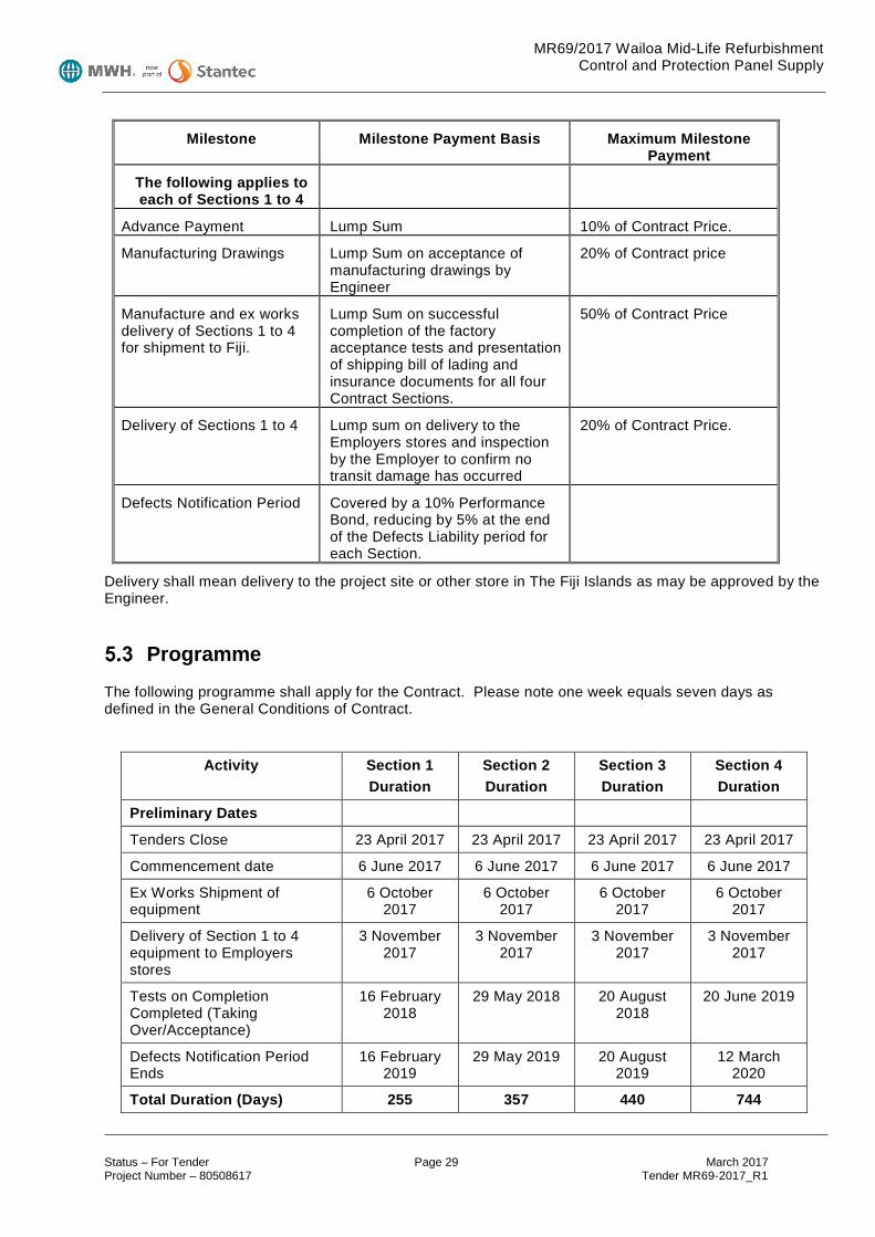
MR69/2017 Wailoa Mid-Life Refurbishment Control and Protection Panel Supply
Status – For Tender Page 29 March 2017 Project Number – 80508617 Tender MR69-2017_R1
Milestone Milestone Payment Basis Maximum Milestone Payment
The following applies to each of Sections 1 to 4
Advance Payment Lump Sum 10% of Contract Price.
Manufacturing Drawings Lump Sum on acceptance of manufacturing drawings by Engineer
20% of Contract price
Manufacture and ex works delivery of Sections 1 to 4 for shipment to Fiji.
Lump Sum on successful completion of the factory acceptance tests and presentation of shipping bill of lading and insurance documents for all four Contract Sections.
50% of Contract Price
Delivery of Sections 1 to 4 Lump sum on delivery to the Employers stores and inspection by the Employer to confirm no transit damage has occurred
20% of Contract Price.
Defects Notification Period Covered by a 10% Performance Bond, reducing by 5% at the end of the Defects Liability period for each Section.
Delivery shall mean delivery to the project site or other store in The Fiji Islands as may be approved by the Engineer.
Programme The following programme shall apply for the Contract. Please note one week equals seven days as defined in the General Conditions of Contract.
Activity Section 1 Duration
Section 2 Duration
Section 3 Duration
Section 4 Duration
Preliminary Dates
Tenders Close 23 April 2017 23 April 2017 23 April 2017 23 April 2017
Commencement date 6 June 2017 6 June 2017 6 June 2017 6 June 2017
Ex Works Shipment of equipment
6 October 2017
6 October 2017
6 October 2017
6 October 2017
Delivery of Section 1 to 4 equipment to Employers stores
3 November 2017
3 November 2017
3 November 2017
3 November 2017
Tests on Completion Completed (Taking Over/Acceptance)
16 February 2018
29 May 2018 20 August 2018
20 June 2019
Defects Notification Period Ends
16 February 2019
29 May 2019 20 August 2019
12 March 2020
Total Duration (Days) 255 357 440 744

MR69/2017 Wailoa Mid-Life Refurbishment Control and Protection Panel Supply
Status – For Tender Page 30 March 2017 Project Number – 80508617 Tender MR69-2017_R1
A detailed schedule must be provided 4 weeks after the Contract Acceptance.
Tests on Completion
5.4.1 Tests on Completion The Tests on Completion for each Section are detailed in Part 8.4 of the Specification.
5.4.2 Tests after Completion
It is expected that all Tests on Completion of the each panel assembly will as Tests after Completion owing to station operating requirements.
5.4.3 Acceptance Certificate
When the above tests are successfully completed the Engineer will issue an Acceptance Certificate confirming the tests have been carried out and the test criteria has been met.
5.4.4 Performance Shortfall during Defects Notification Period
Should any performance shortfall be identified during the Defects Notification Period, the Contractor shall be responsible for taking immediate steps to determine and effectively correct the fault. The performance test shall be repeated by the Contractor after any resulting plant modifications.
Delivery Procedures In the event of plant or sections thereof being supplied from outside The Fiji Islands, such plant shall be delivered to a port in the country of manufacture for direct shipment to the specified port in Fiji. Plant must not be shipped on deck unless in containers.
The Contractor shall: • Arrange for a mutually approved authority to inspect the manufacture, witness testing of the plant
and certify that materials, tests and specifications meet the Employer's requirements and comply with the requirements of those codes specified by the Employer;
• Arrange an independent survey certificate verifying that the packing is adequate and sufficient for the required land, ocean and/or air transit to the final destination determined by the Employer certifying in particular that the packing complies with Fiji Government Regulations;
• the wooden packing cases or timber used in packing machinery for shipment are free of bark and/or obvious insect damage, are certified and cleared by the overseas shippers and that all packing is clean and new;
• Supply to the Employer copies of both of these certificates with the shipping documents; and • Indemnify the Employer against all liabilities, claims, costs and expenses that may result from
failure of the Contractor to comply with the above mentioned conditions;
All wooden packing cases or timber used in packing machinery from overseas shall be fumigated prior to delivery to Site and following equipment unpacking it shall be delivered to a nominated Site area for incineration. This material shall not be used on Site for construction activities.

MR69/2017 Wailoa Mid-Life Refurbishment Control and Protection Panel Supply
Status – For Tender Page 31 March 2017 Project Number – 80508617 Tender MR69-2017_R1
Manuals and As-Built Drawings The Contractor shall provide three securely bound sets of Operating and Maintenance Manuals together with three copies of as built drawings including full process and instrumentation diagrams. A full draft manual shall be provided prior to the issue of a Taking-Over Certificate with three copies of the final revision provided, at least one copy to be on CD-ROM.
The information provided with each manual shall include but not necessarily be limited to:
• All manufacturers’ components design specifications, model numbers, manuals and information;
• Panel layout drawings;
• Shop test reports.
• List of critical and recommended spares.
The final format of all such manuals and drawings shall be agreed with the Engineer prior to their preparation.
Drawings shall also be supplied as hard copies and also in electronic form.
Documentation and Approvals The Contractor shall allow 14 days for the approval by the Engineer of all drawings, schedules and documents as required under this Contract unless such lesser time is agreed in writing by the Engineer. The Contractor shall allow for up to four copies of each and every drawing and document necessary for the approval of the proposed plant and for the subsequent operation and maintenance of the plant. Electronic copies of CAD drawings shall also be provided in AutoCAD format.
Substitutions
All components and engineering specifications shall comply with the technical specification unless agreed to in writing by the Engineer.
Substitutions of alternative equipment or brands of component types shall be approved by the Engineer in writing prior to commitment and installation. Substitutions of the Protective Relay and PLC hardware specified will not be permitted and tenders based on alternatives will be rejected without further evaluation.
Quality Systems and Standard Compliance The Contractor shall implement full Quality Management System procedures on all aspects of the Work from and including initial design to final documentation.
The Engineer reserves the right to arrange an independent assessment of the Contractor's or Plant Suppliers Quality Management System if quality systems procedures in use on the Contract are considered by the Engineer to be deficient.
Manufacturing Photographs During the manufacturing progress on any part of the Works, the Contractor shall take photographic records and include these in progress reports to the Engineer.
Advertising The Contractor shall treat the Contract and everything within it as private and confidential. In particular the Contractor shall not publish any information, drawing or photograph relating to the Works and shall not use

MR69/2017 Wailoa Mid-Life Refurbishment Control and Protection Panel Supply
Status – For Tender Page 32 March 2017 Project Number – 80508617 Tender MR69-2017_R1
the Site for advertising purposes except with the written consent of the Engineer and subject to such conditions as the Engineer may prescribe.
Protection of Works
Where required, the Contractor shall cover and protect the Works and all plant and equipment from inclement weather and damage as the Works proceeds. Any work, materials, plant or equipment suffering damage shall be made good at the Contractor's expense.
MR69/2017 Wailoa Mid-Life Refurbishment Control and Protection Panel Supply
Status – For Tender Page 33 March 2017 Project Number – 80508617 Tender MR69-2017_R1
6 Specification - Introduction Scope of Supply
The Contractor shall furnish all labour, materials and equipment (except ‘free issue’ equipment) required to design, manufacture, factory test and deliver to the Site or Employers store protective relaying, and control panel assemblies as follows:-
• Four (4) turbine generator unit main protection panels. • Four (4) turbine generator unit backup protection panels. • Four (4) turbine generator unit control panel suites (2 panels per suite). • One (1) power station common services control panel. • One (1) intake control panel. • One (1) computer server panel.
Equipment used shall be a type having an established reputation of two years or more of satisfactory and reliable service, designed for auxiliary power and motor control to hydroelectric generators 20 MVA and larger. The requirements of this specification for the design apply to all units.
Equipment and accessories shall be, to the greatest extent practicable, of a type which is readily available in the domestic market or which can be readily imported from Australia or New Zealand. The names of manufacturers of mechanical and electrical auxiliary equipment to be incorporated into the Work, together with performance characteristics, and other significant information, including specification sheets, equipment data, shall be submitted to the Employer for review and acceptance. Equipment shall not be incorporated into the Work without prior review and acceptance by the Employer.
The Contractor will provide equipment for incorporation into the panel assemblies as detailed in this Specification. As an Option, the Employer may elect to provide the items scheduled in Part 9 as “Free issue”. The Employer will elect whether or not to exercise this option prior to the Commencement Date.
The erection, field testing and commissioning of the control and protection equipment will be performed by others.
MR69/2017 Wailoa Mid-Life Refurbishment Control and Protection Panel Supply
Status – For Tender Page 34 March 2017 Project Number – 80508617 Tender MR69-2017_R1
7 General Requirements The following sections and paragraphs written in the singular form for one control and protection panel system shall apply equally to all control and protection panel systems furnished, except where specifically indicated otherwise.
The basic materials and methods shall be in accordance with the Common Requirements Specification.
Submittals Submittals shall be provided in accordance with the requirements of Part 1.3 of the Common Requirements Specification.
7.1.1 Design The following design documents shall be provided by the Employer:
a) Outline Panel Layout Drawings (Included with tender) b) Schematic/Elementary Diagrams (Provided on Contract award) c) Relay Assembled Forms Diagrams (Provided on Contract award). d) Nameplate Schedules (Provided on Contract award).
Based on the Employers Drawings the Contractor shall provide “shop” drawings for manufacturing purposes including:
a) Detail Drawings: • Panel front, rear and side views. • Inside view of equipment arrangements, including terminal blocks and cable entrance
details for external cables. b) Wiring tables (if considered necessary by the Contractor)
7.1.2 Records and Instructions The following records and instructions shall be provided:
a) Shop Test Reports. b) Operating and Maintenance Instructions for all sub-components supplied by the Contractor. c) As manufactured drawings (red-pen markup for Employer provided drawings and amended CAD
drawings for Contractor provided drawings.
References, Specifications, Codes and Standards The Contractor shall comply with requirements of the Common Requirements Specification and the latest revisions of applicable industry standards, specifically including the following:
AS/NZS 3000 Electrical Installations
AS/NZS 3100 Approval and Test Specification – General Requirements for Electrical Equipment
AS/NZS 3111 Approval and Test Specification – Miniature Overcurrent Circuit-Breakers
AS/NZS IEC 61439 Low-voltage Switchgear and Controlgear Assemblies
IEC 60255 Measuring relays and protection equipment - All Relevant Parts
IEC 61000 Electromagnetic Compatibility

MR69/2017 Wailoa Mid-Life Refurbishment Control and Protection Panel Supply
Status – For Tender Page 35 March 2017 Project Number – 80508617 Tender MR69-2017_R1
8 Panel Descriptions General
The following drawings and schematics are provided as part of the Tender package:-
W4-BAY-E001 Unit 4 Single Line Relay Diagram (Unit 3 identical)
W4-BAY-E002 Unit 4 CT & VT Diagram Part 1 (Unit 3 identical)
W4-BAY-E003 Unit 4 CT & VT Diagram Part 2 (Unit 3 identical)
W4-BAY-E004 Unit 4 CT & VT Diagram Part 3 (Unit 3 identical)
W4-BAY-E005 Unit 4 CT & VT Diagram Part 4 (Unit 3 identical)
W4-BAY-E006 Unit 4 CT & VT Diagram Part 5 (Unit 3 identical)
W2-CHA-E001 Unit 2 Protection Panel +2CHA10 Layout (Unit 1 identical)
W4-CHA-E001 Unit 4 Protection Panel +4CHA20 Layout (Unit 3 identical)
W1-CJA-SK01 Unit 1 Control Panel +1CJA01 Layout (Sketch) (Units 2, 3 & 4 identical)
W1-CJA-SK02 Unit 1 Control Panel +1CJA02 Layout (Sketch) (Units 2, 3 & 4 identical)
W1-CJA-SK03 Unit 1 PLC Architecture Sheet 1 (Sketch) (Units 2, 3 & 4 identical)
W1-CJA-SK04 Unit 1 PLC Architecture Sheet 2 (Sketch) (Units 2, 3 & 4 identical)
W1-CJA-SK05 Unit 1 Tripping Scheme (Sketch) (Units 2, 3 & 4 identical)
W0-CKA-SK01 Control system architecture (Sketch)
W0-CKA-SK02 Protection System communications architecture (Sketch)
The Unit 1 and 2 protection systems differ from units 3 & 4 in that:-
• Units 1 & 2 have no SEL387L relay. • Units 1 & 2 have no auxiliary transformer.
Detailed schedules of required protection relay and PLC hardware are provided in Part 9 of this specification.
As noted in Part 7.1.1 the Employer will provide full schematics of the protection and control panel wiring to the Contractor for manufacturing purposes. These will be provided one week following the Commencement Date.
Units 1&2 Main Protection Panel (2 panels in total) +01CHA10 & +02CHA10
Each comprising:-
1 x 600mm (Wide) x 800mm (Deep) x 2100mm (High) rack front cubicle.
1 x SEL 700G generator main protection relay - K101
1 x SEL 487E transformer main protection relay - K105
1 x SEL 387L tie line protection relay - K106
1 x SEL 2505 remote IO module - FCT
9 x GE MMLG 01 test blocks. - TB01, 03, 04, 06, 09, 11, 12, 13, 32
1 x SEL-2730M Ethernet Switch - K108
1 x Fibre Optic termination box, with 12 x SC Simplex adapters.
1 x set sundry items as detailed in Clause 3.10.

MR69/2017 Wailoa Mid-Life Refurbishment Control and Protection Panel Supply
Status – For Tender Page 36 March 2017 Project Number – 80508617 Tender MR69-2017_R1
Units 3&4 Main Protection Panel (2 panels in total) +03CHA10 & +04CHA10
Each comprising:-
1 x 600mm (Wide) x 800mm (Deep) x 2100mm (High) rack front cubicle.
1 x SEL 700G main generator protection relay - K101
1 x SEL 487E main transformer protection relay - K105
1 x SEL 2505 remote IO module - K106
8 x GE MMLG 01 test blocks. - TB01, 03, 04, 06, 09, 11, 12, 32
1 x SEL-2730M Ethernet Switch - K108
1 x Fibre Optic termination box, with 12 x SC Simplex adapters.
1 x set sundry items as detailed in Clause 3.10.
Units 1-4 Backup Protection Panel (4 panels in total) +01CHA20, +02CHA20, +03CHA20, +04CHA20
Each comprising:-
1 x 600mm (Wide) x 800mm (Deep) x 2100mm (High) rack front cubicle.
1 x SEL 700G generator backup protection relay - K102
1 x SEL 751 excitation protection relay - K103
1 x SEL 2533 annunciator - K104
1 x SEL 351S transformer backup protection relay - K107
5 x GE MMLG test blocks. - TB02, 05, 07, 08, 10
1 x set sundry items as detailed in Clause 3.10.
Units 1-4 Unit Control Panel 1/2 (4 panels in total) +01CJA01, +02CJA01, +03CJA01, +04CJA01
Each comprising:-
1 x 800mm (Wide) x 800mm (Deep) x 2100mm (High) rack front cubicle.
2 x Schneider M580 PLC Processor racks as further detailed in Part 9.
2 x Schneider M580 PLC IO racks as further detailed in Part 9.
1 x Advantech PPC-4151W-P5AE 15” Panel PC, complete with MS Windows (64 bit), rack mounting kit and 500Gb SSD.
2 x 110V/24V 240W DC/DC convertors – Phoenix Contact QUINT-PS/1AC/24DC/10/CO or equal.
1 x 24V diode redundancy module – Phoenix Contact QUINT-ORING/24DC/2X10/1X20 or equal.
1 x SEL-2730M Ethernet Switch
1 x Fibre Optic termination box, with 12 x SC Simplex adapters.
1 x Remote/Off/Local selector switch.
1 x 22.5mm Estop/lockout switch.
3 x 22.5mm pushbuttons.
5 x 22.5mm led lamps.
1 x set sundry items as detailed in Clause 3.10.

MR69/2017 Wailoa Mid-Life Refurbishment Control and Protection Panel Supply
Status – For Tender Page 37 March 2017 Project Number – 80508617 Tender MR69-2017_R1
Units 1-4 Unit Control Panel 2/2 (4 panels in total) +01CJA02, +02CJA02, +03CJA02, +04CJA02
Each comprising:-
1 x 800mm (Wide) x 800mm (Deep) x 2100mm (High) rack front cubicle.
2 x Schneider M580 PLC IO racks as further detailed in Part 9.
2 x 110V/24V 240W DC/DC convertors – Phoenix Contact QUINT-PS/1AC/24DC/10/CO or equal.
1 x 24V diode redundancy module – Phoenix Contact QUINT-ORING/24DC/2X10/1X20 or equal.
2 x Revenue meter - Shark 200-50Hz-2-V1-D2-INP100S-X.
1 x Multifunction meter - Schneider PM1200 - METSEPM1200.
2 x Metering test blocks - Rudolf or equal.
1 x Manual synchroniser – Iskra SQ0214-D-L-2-1-0-0-0 or equal.
1 x Auto/Off/Manual selector switch.
1 x Circuit breaker trip/close discrepancy switch – Comelectric DR20 or equal.
2 x lockout trip relays – ABB RXMB4 RK251-402-AN plus red flag RK251-900-XR
10 x auxiliary relays – Finder 55.34.9.110.0040 plus 94.04 base or equal
1 x Tachpak T77530-10 digital tachometer (Recovered from existing panel on site – will be fitted to this panel on site).
1 x set sundry items as detailed in Clause 3.10.
Each of the lockout trip (86A & B) relays located in Unit Control Panel 2/2 shall be wired to provide the generator shutdown circuits as indicated schematically in Drawing W1-CJA-SK03. The 86 relays shall be energised to trip and the activating conditions shall be wired in parallel. Two terminal blocks shall be provided for the field side connection of each activating condition external to the Unit Control Panel. Each lockout trip relay shall be supplied from a 10A, dual pole 110V DC MCB, with auxiliary contact. A power supply monitoring relay shall be provided to monitor each 110V supply. The lockout trip relay contacts shall be wired to terminal blocks for connection to the field isolating devices (inlet valve, generator circuit breaker etc).
Two dual pole 110V DC MCBs, each with auxiliary contact and power supply monitoring relay shall be provided for the 11kV generator circuit breaker trip and close controls.
Common Services Control Panel (1 panels in total) +00CMA01
Comprising:-
1 x 800mm (Wide) x 800mm (Deep) x 2100mm (High) rack front cubicle.
2 x Schneider M580 PLC Processor racks as further detailed in Part 9.
2 x Schneider M580 PLC IO racks as further detailed in Part 9.
2 x 110V/24V 240W DC/DC convertors – Phoenix Contact QUINT-PS/1AC/24DC/10/CO or equal.
1 x 24V diode redundancy module – Phoenix Contact QUINT-ORING/24DC/2X10/1X20 or equal.
1 x SEL-2488 Network clock.
1 x SEL2032 communications processor (Recovered from existing panel on site – will be fitted to this panel on site).
2 x SEL-2730M Ethernet Switches
1 x Fibre Optic termination box, with 12 x SC Simplex adapters.
5 x 22.5mm led lamps.
1 x set sundry items as detailed in Clause 3.10.
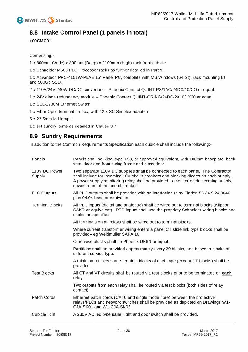
MR69/2017 Wailoa Mid-Life Refurbishment Control and Protection Panel Supply
Status – For Tender Page 38 March 2017 Project Number – 80508617 Tender MR69-2017_R1
Intake Control Panel (1 panels in total) +00CMC01
Comprising:-
1 x 800mm (Wide) x 800mm (Deep) x 2100mm (High) rack front cubicle.
1 x Schneider M580 PLC Processor racks as further detailed in Part 9.
1 x Advantech PPC-4151W-P5AE 15” Panel PC, complete with MS Windows (64 bit), rack mounting kit and 500Gb SSD.
2 x 110V/24V 240W DC/DC convertors – Phoenix Contact QUINT-PS/1AC/24DC/10/CO or equal.
1 x 24V diode redundancy module – Phoenix Contact QUINT-ORING/24DC/2X10/1X20 or equal.
1 x SEL-2730M Ethernet Switch
1 x Fibre Optic termination box, with 12 x SC Simplex adapters.
5 x 22.5mm led lamps.
1 x set sundry items as detailed in Clause 3.7.
Sundry Requirements In addition to the Common Requirements Specification each cubicle shall include the following:-
Panels Panels shall be Rittal type TS8, or approved equivalent, with 100mm baseplate, back steel door and front swing frame and glass door.
110V DC Power Supply
Two separate 110V DC supplies shall be connected to each panel. The Contractor shall include for incoming 10A circuit breakers and blocking diodes on each supply. A power supply monitoring relay shall be provided to monitor each incoming supply, downstream of the circuit breaker.
PLC Outputs All PLC outputs shall be provided with an interfacing relay Finder 55.34.9.24.0040 plus 94.04 base or equivalent
Terminal Blocks All PLC inputs (digital and analogue) shall be wired out to terminal blocks (Klippon SAKR or equivalent). RTD inputs shall use the propriety Schneider wiring blocks and cables as specified.
All terminals on all relays shall be wired out to terminal blocks.
Where current transformer wiring enters a panel CT slide link type blocks shall be provided– eg Weidmuller SAKA 10.
Otherwise blocks shall be Phoenix UK6N or equal.
Partitions shall be provided approximately every 20 blocks, and between blocks of different service type.
A minimum of 10% spare terminal blocks of each type (except CT blocks) shall be provided.
Test Blocks All CT and VT circuits shall be routed via test blocks prior to be terminated on each relay.
Two outputs from each relay shall be routed via test blocks (both sides of relay contact).
Patch Cords Ethernet patch cords (CAT6 and single mode fibre) between the protective relays/PLCs and network switches shall be provided as depicted on Drawings W1-CJA-SK01 and W1-CJA-SK02.
Cubicle light A 230V AC led type panel light and door switch shall be provided.

MR69/2017 Wailoa Mid-Life Refurbishment Control and Protection Panel Supply
Status – For Tender Page 39 March 2017 Project Number – 80508617 Tender MR69-2017_R1
Cubicle heater A 230V cubicle heater and thermostat shall be provided.
Degree of ingress protection:
Minimum Enclosure IP42 (doors closed), IP2X (doors opened).
Cabling: Bottom cable entry, front controls and component access and rear cable connection access. Gland plates shall be provided at the top and bottom of the cubicle.
Factory Inspection and Testing The panels shall be completely assembled in the factory and tested, insofar as practicable.
Tests shall include:
• All control, instrument, CT, VT and relay wiring shall be subjected to a dry dielectric withstand test of 2,500-V to ground for one minute.
• Secondary injection tests to demonstrate correct operation of all protection settings (Settings provided by Employer).
• Function tests to demonstrate the correct operation of all wiring, including protective relay and PLC IO, auxiliary relays etc.
Installation, Testing and Commissioning The equipment shall be installed, field tested, and placed in operation by the Employer.
Spare Parts 8.12.1 Specified Spare Parts 1 x 110V/24V 240W DC/DC convertors – Phoenix Contact QUINT-PS/1AC/24DC/10/CO or equal.
1 x 24V diode redundancy module – Phoenix Contact QUINT-ORING/24DC/2X10/1X20 or equal.
1 x Schneider M580 PLC components as further detailed in Part 9.
8.12.2 Optional Spare Parts The Contractor shall furnish a list of recommended Optional additional spare parts.
Panel Data Provide catalogue data for each major component of the panel system and ancillary devices showing ratings and characteristics proposed.
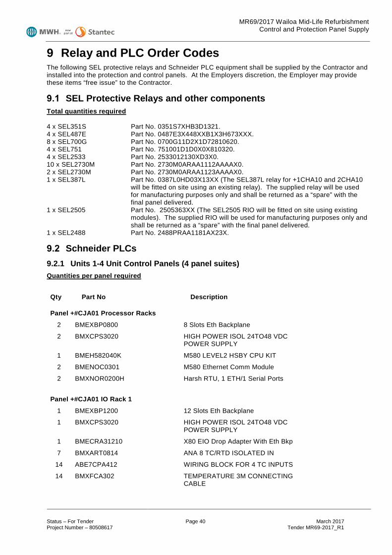
MR69/2017 Wailoa Mid-Life Refurbishment Control and Protection Panel Supply
Status – For Tender Page 40 March 2017 Project Number – 80508617 Tender MR69-2017_R1
9 Relay and PLC Order Codes The following SEL protective relays and Schneider PLC equipment shall be supplied by the Contractor and installed into the protection and control panels. At the Employers discretion, the Employer may provide these items “free issue” to the Contractor.
SEL Protective Relays and other components Total quantities required 4 x SEL351S Part No. 0351S7XHB3D1321. 4 x SEL487E Part No. 0487E3X448XXB1X3H673XXX. 8 x SEL700G Part No. 0700G11D2X1D72810620. 4 x SEL751 Part No. 751001D1D0X0X810320. 4 x SEL2533 Part No. 2533012130XD3X0. 10 x SEL2730M Part No. 2730M0ARAA1112AAAAX0. 2 x SEL2730M Part No. 2730M0ARAA1123AAAAX0. 1 x SEL387L Part No. 0387L0HD03X13XX (The SEL387L relay for +1CHA10 and 2CHA10
will be fitted on site using an existing relay). The supplied relay will be used for manufacturing purposes only and shall be returned as a “spare” with the final panel delivered.
1 x SEL2505 Part No. 2505363XX (The SEL2505 RIO will be fitted on site using existing modules). The supplied RIO will be used for manufacturing purposes only and shall be returned as a “spare” with the final panel delivered.
1 x SEL2488 Part No. 2488PRAA1181AX23X.
Schneider PLCs 9.2.1 Units 1-4 Unit Control Panels (4 panel suites) Quantities per panel required
Qty Part No Description
Panel +#CJA01 Processor Racks
2 BMEXBP0800 8 Slots Eth Backplane
2 BMXCPS3020 HIGH POWER ISOL 24TO48 VDC POWER SUPPLY
1 BMEH582040K M580 LEVEL2 HSBY CPU KIT
2 BMENOC0301 M580 Ethernet Comm Module
2 BMXNOR0200H Harsh RTU, 1 ETH/1 Serial Ports
Panel +#CJA01 IO Rack 1
1 BMEXBP1200 12 Slots Eth Backplane
1 BMXCPS3020 HIGH POWER ISOL 24TO48 VDC POWER SUPPLY
1 BMECRA31210 X80 EIO Drop Adapter With Eth Bkp
7 BMXART0814 ANA 8 TC/RTD ISOLATED IN
14 ABE7CPA412 WIRING BLOCK FOR 4 TC INPUTS
14 BMXFCA302 TEMPERATURE 3M CONNECTING CABLE
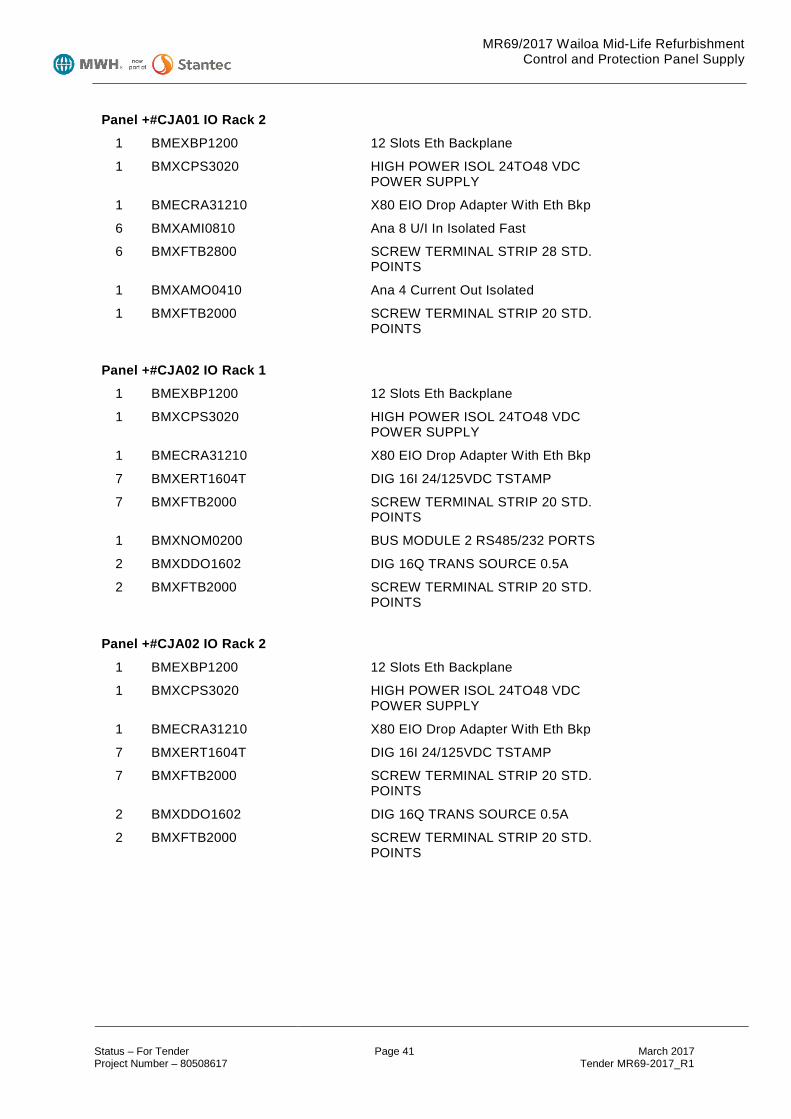
MR69/2017 Wailoa Mid-Life Refurbishment Control and Protection Panel Supply
Status – For Tender Page 41 March 2017 Project Number – 80508617 Tender MR69-2017_R1
Panel +#CJA01 IO Rack 2
1 BMEXBP1200 12 Slots Eth Backplane
1 BMXCPS3020 HIGH POWER ISOL 24TO48 VDC POWER SUPPLY
1 BMECRA31210 X80 EIO Drop Adapter With Eth Bkp
6 BMXAMI0810 Ana 8 U/I In Isolated Fast
6 BMXFTB2800 SCREW TERMINAL STRIP 28 STD. POINTS
1 BMXAMO0410 Ana 4 Current Out Isolated
1 BMXFTB2000 SCREW TERMINAL STRIP 20 STD. POINTS
Panel +#CJA02 IO Rack 1
1 BMEXBP1200 12 Slots Eth Backplane
1 BMXCPS3020 HIGH POWER ISOL 24TO48 VDC POWER SUPPLY
1 BMECRA31210 X80 EIO Drop Adapter With Eth Bkp
7 BMXERT1604T DIG 16I 24/125VDC TSTAMP
7 BMXFTB2000 SCREW TERMINAL STRIP 20 STD. POINTS
1 BMXNOM0200 BUS MODULE 2 RS485/232 PORTS
2 BMXDDO1602 DIG 16Q TRANS SOURCE 0.5A
2 BMXFTB2000 SCREW TERMINAL STRIP 20 STD. POINTS
Panel +#CJA02 IO Rack 2
1 BMEXBP1200 12 Slots Eth Backplane
1 BMXCPS3020 HIGH POWER ISOL 24TO48 VDC POWER SUPPLY
1 BMECRA31210 X80 EIO Drop Adapter With Eth Bkp
7 BMXERT1604T DIG 16I 24/125VDC TSTAMP
7 BMXFTB2000 SCREW TERMINAL STRIP 20 STD. POINTS
2 BMXDDO1602 DIG 16Q TRANS SOURCE 0.5A
2 BMXFTB2000 SCREW TERMINAL STRIP 20 STD. POINTS

MR69/2017 Wailoa Mid-Life Refurbishment Control and Protection Panel Supply
Status – For Tender Page 42 March 2017 Project Number – 80508617 Tender MR69-2017_R1
9.2.2 Station Common Services Control Panel Quantities per panel
Qty Part No. Description
+00CMA01 Processor Racks
2 BMEXBP0800 8 slots Eth backplane
2 BMXCPS3020 HIGH POWER ISOL 24TO48 VDC POWER SUPPLY
1 BMEH582040K M580 LEVEL2 HSBY CPU KIT
2 BMENOC0301 M580 Ethernet Comm Module
2 BMXNOR0200H Harsh RTU, 1 ETH/1 Serial ports
+00CMA01 IO Rack
1 BMEXBP1200 12 slots Eth backplane
1 BMXCPS3020 HIGH POWER ISOL 24TO48 VDC POWER SUPPLY
1 BMECRA31210 X80 EIO Drop adapter with Eth Bkp
4 BMXERT1604T DIG 16I 24/125VDC TSTAMP
4 BMXFTB2000 SCREW TERMINAL STRIP 20 STD. POINTS
4 BMXDDO1602 DIG 16Q TRANS SOURCE 0.5A
4 BMXFTB2000 SCREW TERMINAL STRIP 20 STD. POINTS
2 BMXAMI0810 Ana 8 U/I In Isolated Fast
2 BMXFTB2800 SCREW TERMINAL STRIP 28 STD. POINTS
9.2.3 Intake Services Control Panel Quantities per panel
Qty Part No. Description
+00CMA01 Processor & IO Rack
1 BMXXBP0800 8 SLOTS BACKPLANE
1 BMXCPS3020 HIGH POWER ISOL 24TO48 VDC POWER SUPPLY
1 BMXP342020 CPU340-20 MODBUS ETHERNET
2 BMXERT1604T DIG 16I 24/125VDC TSTAMP
2 BMXFTB2000 SCREW TERMINAL STRIP 20 STD. POINTS
1 BMXDDO1602 DIG 16Q TRANS SOURCE 0.5A
1 BMXFTB2000 SCREW TERMINAL STRIP 20 STD. POINTS
1 BMXAMI0810 Ana 8 U/I In Isolated Fast

MR69/2017 Wailoa Mid-Life Refurbishment Control and Protection Panel Supply
Status – For Tender Page 43 March 2017 Project Number – 80508617 Tender MR69-2017_R1
1 BMXFTB2800 SCREW TERMINAL STRIP 28 STD. POINTS
9.2.4 Spare Parts
Qty Part No. Description
1 BMEXBP800 8 Slots Eth Backplane
1 BMEXBP1200 12 Slots Eth Backplane
2 BMXCPS3020 HIGH POWER ISOL 24TO48 VDC POWER SUPPLY
1 BMEH582040K M580 LEVEL2 HSBY CPU KIT
1 BMENOC0301 M580 Ethernet Comm Module
1 BMXART0814 ANA 8 TC/RTD ISOLATED IN
1 BMXAMI0810 Ana 8 U/I In Isolated Fast
1 BMXERT1604T DIG 16I 24/125VDC TSTAMP
1 BMXDDO1602 DIG 16Q TRANS SOURCE 0.5A
1 BMXNOR0200H Harsh RTU, 1 ETH/1 Serial ports

MR69/2017 Wailoa Mid-Life Refurbishment Control and Protection Panel Supply
Status – For Tender Page 44 March 2017 Project Number – 80508617 Tender MR69-2017_R1
Schedule 1 – Tender Forms

MR69/2017 Wailoa Mid-Life Refurbishment Control and Protection Panel Supply
Status – For Tender Page 45 March 2017 Project Number – 80508617 Tender MR69-2017_R1
Tender Form 1 – Letter of Tender
Name of Contract: Wailoa Mid Life Refurbishment Project, Control and Protection Panel Supply Contract No. MR69/2017 Tender To: Fiji Electricity Authority 2 Marlow St Private Mail Bag Suva Republic of the Fiji Islands 1. This tender is made by ____________________________________________________
[insert full name and registered address of tenderer]. 2. Capitalised terms used in this letter have the meaning given to them in the Instructions to tenderers
dated [insert date] (“Instructions”) unless otherwise defined. 3. Having examined and understood the Tender Documents relating to the Works (including the
Instructions and all documents attached thereto, including but not limited to the Particular Conditions of Contract, the General Conditions of Contract, the Specification and the Employer’s Drawings) we, the undersigned, hereby offer to design, execute, complete and remedy defects in the whole of the Works in conformity with the said documents for the sum of:
…....................................................................................................................... ........................................................................................, ($...........................), Exclusive of VAT, WHT or such other sum as may be ascertained in accordance with the Contract. 4. This offer is made on the terms and conditions set out in this Tender and the Instructions. 5. We attach the following documents which form part of this tender:
(a) Completed tender forms; (b) Technical description of the plant offered; (c) Proposed programme; (d) Any supplementary information;
6. We agree to abide by this Tender for a period of 60 days after the Tender Closing Date and that this Tender it shall remain binding upon us and may be accepted by you at any time before the expiration of that period.
7. We confirm that you may rely upon all statements made by us in response to the Instructions or in subsequent correspondence, discussions or negotiations with you.
8. We certify that: (a) The entry into, and performance of the obligations under, the Contract by us will not violate any
laws provided that you obtain all consents and authorisations you are required to obtain under the Contract;
(b) We have corporate power to enter into and perform our obligations under the Contract and we have taken all necessary corporate action to authorise the entry into, and execution of, this offer and (if required) entry into, and execution of, the Contract;
(c) The rates and prices in our offer have been arrived at independently, without consultation or agreement with any other tenderer; and
(d) No attempt has been made, nor will be made, by us to influence any other tenderer to submit or not submit a tender or to alter the proposed content of that tenderer's tender.
9. We acknowledge that this tender, and any contract arising upon its acceptance, shall be governed by and construed in accordance with the laws of The Fiji Islands.
10. Unless and until a formal agreement is prepared and executed, this Letter of Tender, together with your written acceptance thereof, shall constitute a binding contract between us.
We understand that you are not bound to accept the lowest or any tender you may receive. Dated this day of 2016 Signature in the capacity of __________________________________ duly authorised to sign Tenders for and on behalf of: ___________________________ Witness _______________________________________________

MR69/2017 Wailoa Mid-Life Refurbishment Control and Protection Panel Supply
Status – For Tender Page 46 March 2017 Project Number – 80508617 Tender MR69-2017_R1
Address _______________________________________________ Occupation _______________________________________________

MR69/2017 Wailoa Mid-Life Refurbishment Control and Protection Panel Supply
Status – For Tender Page 47 March 2017 Project Number – 80508617 Tender MR69-2017_R1
Tender Form 2 – Tender Price and Price Breakdown
Item Amount Fijian Dollars (FJD)
excluding VAT
Amount Foreign Currency
(Nominated by Tenderer)
Protection Panels
Unit 1 Main Protection Panel +01CHA10
Unit 2 Main Protection Panel +02CHA10
Unit 3 Main Protection Panel +03CHA10
Unit 4 Main Protection Panel +04CHA10
Unit 1 Backup Protection Panel +01CHA20
Unit 2 Backup Protection Panel +02CHA20
Unit 3 Backup Protection Panel +03CHA20
Unit 4 Backup Protection Panel +04CHA20
Control Panels
Unit 1 Control Panel 1/2 +01CJA01
Unit 2 Control Panel 1/2 +02CJA01
Unit 3 Control Panel 1/2 +03CJA01
Unit 4 Control Panel 1/2 +04CJA01
Unit 1 Control Panel 2/2 +01CJA02
Unit 2 Control Panel 2/2 +02CJA02
Unit 3 Control Panel 2/2 +03CJA02
Unit 4 Control Panel 2/2 +04CJA02
Common Services Control Panel +00CMA01
Intake Control Panel +00CMC01
Spare parts
Delivery to Site
As Manufactured Drawings
Total Tendered Price The above scheduled prices shall include for the SEL protection relays and Schneider PLC hardware.
Item Prices for SEL Protective Relays and Schneider PLC Equipment
Amount Fijian Dollars (FJD)
excluding VAT
Amount Foreign Currency
(Nominated by Tenderer)
SEL 0700G1
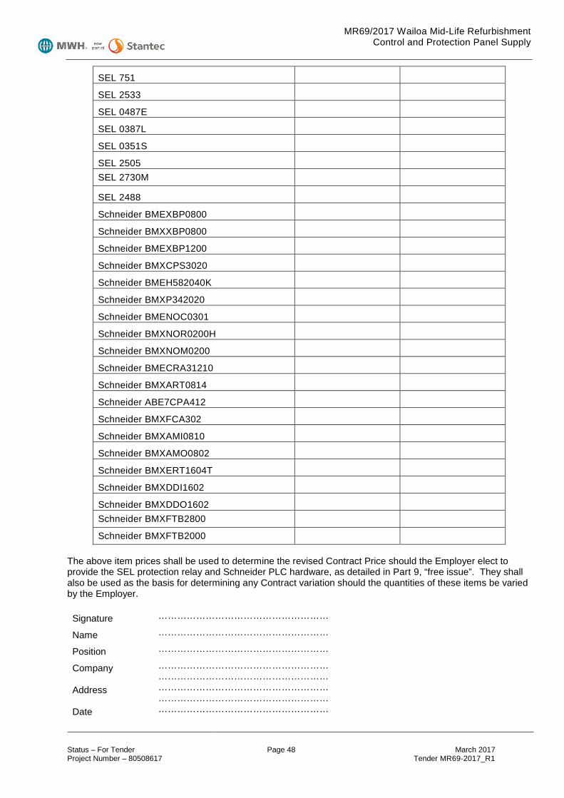
MR69/2017 Wailoa Mid-Life Refurbishment Control and Protection Panel Supply
Status – For Tender Page 48 March 2017 Project Number – 80508617 Tender MR69-2017_R1
SEL 751
SEL 2533
SEL 0487E
SEL 0387L
SEL 0351S
SEL 2505
SEL 2730M
SEL 2488
Schneider BMEXBP0800
Schneider BMXXBP0800
Schneider BMEXBP1200
Schneider BMXCPS3020
Schneider BMEH582040K
Schneider BMXP342020
Schneider BMENOC0301
Schneider BMXNOR0200H
Schneider BMXNOM0200
Schneider BMECRA31210
Schneider BMXART0814
Schneider ABE7CPA412
Schneider BMXFCA302
Schneider BMXAMI0810
Schneider BMXAMO0802
Schneider BMXERT1604T
Schneider BMXDDI1602
Schneider BMXDDO1602
Schneider BMXFTB2800
Schneider BMXFTB2000 The above item prices shall be used to determine the revised Contract Price should the Employer elect to provide the SEL protection relay and Schneider PLC hardware, as detailed in Part 9, “free issue”. They shall also be used as the basis for determining any Contract variation should the quantities of these items be varied by the Employer. Signature ………………………………………………
Name ………………………………………………
Position ………………………………………………
Company ……………………………………………… ………………………………………………
Address ……………………………………………… ………………………………………………
Date ………………………………………………
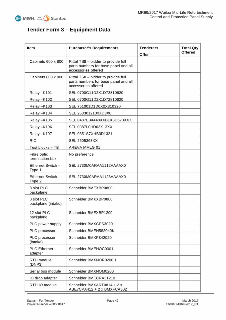
MR69/2017 Wailoa Mid-Life Refurbishment Control and Protection Panel Supply
Status – For Tender Page 49 March 2017 Project Number – 80508617 Tender MR69-2017_R1
Tender Form 3 – Equipment Data
Item Purchaser’s Requirements Tenderers
Offer
Total Qty Offered
Cabinets 600 x 800 Rittal TS8 – bidder to provide full parts numbers for base panel and all accessories offered
Cabinets 800 x 800 Rittal TS8 – bidder to provide full parts numbers for base panel and all accessories offered
Relay –K101 SEL 0700G11D2X1D72810620
Relay –K102 SEL 0700G11D2X1D72810620
Relay –K103 SEL 751001D1D0X0X810320
Relay –K104 SEL 2533012130XD3X0
Relay –K105 SEL 0487E3X448XXB1X3H673XXX
Relay –K106 SEL 0387L0HD03X13XX
Relay –K107 SEL 0351S7XHB3D1321
RIO SEL 2505363XX
Test blocks – TB AREVA MMLG 01
Fibre optic termination box
No preference
Ethernet Switch – Type 1
SEL 2730M0ARAA1112AAAAX0
Ethernet Switch – Type 2
SEL 2730M0ARAA1123AAAAX0
8 slot PLC backplane
Schneider BMEXBP0800
8 slot PLC backplane (intake)
Schneider BMXXBP0800
12 slot PLC backplane
Schneider BMEXBP1200
PLC power supply Schneider BMXCPS3020
PLC processor Schneider BMEH582040K
PLC processor (intake)
Schneider BMXP342020
PLC Ethernet adapter
Schneider BMENOC0301
RTU module (DNP3)
Schneider BMXNOR0200H
Serial bus module Schneider BMXNOM0200
IO drop adapter Schneider BMECRA31210
RTD IO module Schneider BMXART0814 + 2 x ABE7CPA412 + 2 x BMXFCA302

MR69/2017 Wailoa Mid-Life Refurbishment Control and Protection Panel Supply
Status – For Tender Page 50 March 2017 Project Number – 80508617 Tender MR69-2017_R1
AI IO module Schneider BMXAMI0810 + BMXFTB2800
AO IO module Schneider BMXAMO0802 + BMXFTB2000
SOE IO module Schneider BMXERT1604T + BMXFTB2000
DI IO module Schneider BMXDDI1602 + BMXFTB2000
DO IO module Schneider BMXDDO1602 + BMXFTB2000
110V/24V DC/DC convertor
Phoenix Contact QUINT-PS/1AC/24DC/10/CO
24V DC redundancy module
Phoenix Contact QUINT-ORING/24DC/2X10/1X20
HMI monitor Advantech PPC-4151W-P5AE 15” Panel PC, complete with MS Windows (64 bit), rack mounting kit and 500Gb SSD
Revenue meter Shark 200-50Hz-2-V1-D2-INP100S-X
Multifunction Meter Schneider PM1200 - METSEPM1200
Manual synchroniser
Iskra SQ0214-D-L-2-1-0-0-0
CB discrepancy switch
Comelectric DR20
PLC IO terminal block type
SAKR
CT terminal block type
SAKA 10
Other terminal block type
UK6N
Trip lockout relays ABB RXMB4 RK251-402-AN plus red flag RK251-900-XR
110V DC coil auxiliary relays
Finder 55.34.9.110.0040 plus 94.04 base
24V DC coil auxiliary relays
Finder 55.34.9.24.0040 plus 94.04 base
Auto/Off/Manual selector switch
No preference
Remote/Off/Local selector switch.
No preference
22.5mm Estop/lockout switch
No preference
22.5mm pushbutton No preference
22.5mm led lamps No preference
CAT6 patch leads No preference
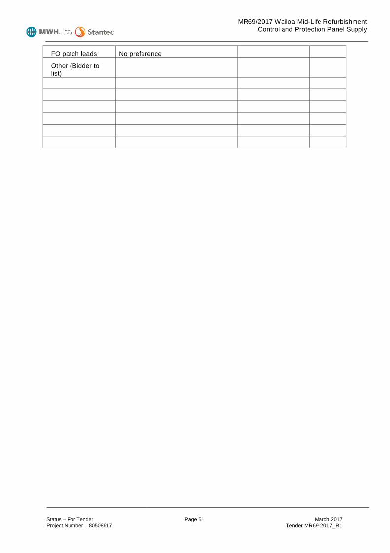
MR69/2017 Wailoa Mid-Life Refurbishment Control and Protection Panel Supply
Status – For Tender Page 51 March 2017 Project Number – 80508617 Tender MR69-2017_R1
FO patch leads No preference
Other (Bidder to list)

MR69/2017 Wailoa Mid-Life Refurbishment Control and Protection Panel Supply
Status – For Tender Page 52 March 2017 Project Number – 80508617 Tender MR69-2017_R1
Tender Form 4 – Proposed Suppliers and Sub-Contractors
…………………………………………………
…………………………………………………
…………………………………………………
………………………………………………… Signature ………………………………………………
Name ………………………………………………
Position ………………………………………………
Company ……………………………………………… ………………………………………………
Address ……………………………………………… ………………………………………………
Date ………………………………………………

MR69/2017 Wailoa Mid-Life Refurbishment Control and Protection Panel Supply
Status – For Tender Page 53 March 2017 Project Number – 80508617 Tender MR69-2017_R1
Tender Form 5 – Percentage On-Costs
Item Description Percentage on Cost 1. Equipment and materials supplied on cost plus basis
(including transport). .............................. 2. Sub-contractors employed on cost plus basis. .............................. 3. Equipment hire. .............................. 4. Contractor’s profit. ..............................
Explanatory Notes (a) The Tenderer shall complete the Percentage on Costs form to show the percentage on cost applicable
for supplying extra equipment and materials, employing extra Sub-contractors on a cost plus basis and for arranging extra equipment hire.
(b) The percentage on costs shall allow for all costs incurred by and profits for the Contractor in arranging for the supply of any extra equipment and materials or hire of any extra equipment.
(c) The percentage on costs shall allow for all costs incurred by and profits for the Contractor in arranging and managing any extra Sub-contractors employed on the job.
(d) Invoices shall be supplied by the Contractor to substantiate any claim for costs associated with work performed on a cost plus basis.
(e) The percentage on costs and invoices will be used as a basis for agreeing costs associated with any variations to the contract.
Signature ………………………………………………
Name ………………………………………………
Position ………………………………………………
Company ……………………………………………… ………………………………………………
Address ……………………………………………… ………………………………………………
Date ………………………………………………

MR69/2017 Wailoa Mid-Life Refurbishment Control and Protection Panel Supply
Status – For Tender Page 54 March 2017 Project Number – 80508617 Tender MR69-2017_R1
Tender Form 6 – Statement of Conformance We have read and understood the Tender documentation for the generator rehabilitation contract, and confirm that: Tick 1 Box as Applicable
Our Tender is in full compliance with the requirements and we have no exceptions to note.
Our Tender does not fully comply with the requirements. The following exceptions apply:
……………………………………………………………………………………… ……………………………………………………………………………………… ……………………………………………………………………………………… ……………………………………………………………………………………… ……………………………………………………………………………………… ……………………………………………………………………………………… ……………………………………………………………………………………… ………………………………………………………………………………………
Signature ………………………………………………
Name ………………………………………………
Position ………………………………………………
Company ……………………………………………… ………………………………………………
Address ……………………………………………… ………………………………………………
Date ………………………………………………

MR69/2017 Wailoa Mid-Life Refurbishment Control and Protection Panel Supply
Status – For Tender Page 55 March 2017 Project Number – 80508617 Tender MR69-2017_R1
Schedule 2 – Form of Contract Agreement This Agreement is made this day of 2016 Between The Fiji Electricity Authority, (Herein called the Employer) And , (Herein called the Contractor) Whereas A. The Employer requires that certain Works be provided and executed by the Contractor set out in
clause 2 below, the Works being more particularly defined in the Contract documents: B. The Contractor has submitted a Tender to the Employer for the provision and execution of the
Works by the Contractor for the sum of FJ$ plus FX$ (foreign Currency to be nominated at time of tender) (the Contract Price) and the Employer has accepted such Tender:
C. The Employer has appointed Mr Robin Spittle to be the Engineer for the purpose of the Works: NOW THEREFORE the parties are agreed as follows: 1. In this Contract Agreement words and expressions shall have the same meanings as are
respectively assigned to them in the Conditions of Contract hereinafter referred to. 2. The following documents shall be deemed to form and be read and construed as part of this
Agreement:
• Contract Agreement • The Letter of Acceptance • Appendix to Tender • The completed Tender Schedules • Notice to Tenderers (NTT) • Particular Conditions of Contract • General Conditions of Contract • Specifications (with Part 3 taking precedence over Part 4) • Letter of Tender • Contractor's Proposal • Instructions to Tenderers. Should there be any ambiguity or discrepancy between these documents the documents shall take precedence in the order of priority listed above.
3. In consideration of the payments to be made by the Employer to the Contractor in accordance with the Contract, the Contractor shall design, execute and complete the Works and remedy defects therein in conformity in all respects with the provisions of the Contract.
4. The Employer shall pay the Contractor in consideration of the design, execution and completion of
the Works and the remedying of defects therein the Contract Price or such other sum as may come payable under the provisions of the Contract at the times and in the manner prescribed by the Contract.
5. The parties have entered into this Agreement in accordance with their respective laws and statutes or constitutions on the date hereof by their fully authorised signatories.
Binding signature on behalf of the Employer Title: ......................................... ............................................................ Dated: .......................................
MR69/2017 Wailoa Mid-Life Refurbishment Control and Protection Panel Supply
Status – For Tender Page 56 March 2017 Project Number – 80508617 Tender MR69-2017_R1
Binding signature on behalf of the Contractor Title: ......................................... ............................................................ Dated: .......................................

MR69/2017 Wailoa Mid-Life Refurbishment Control and Protection Panel Supply
Status – For Tender Page 57 March 2017 Project Number – 80508617 Tender MR69-2017_R1
Appendix A Employers Drawings
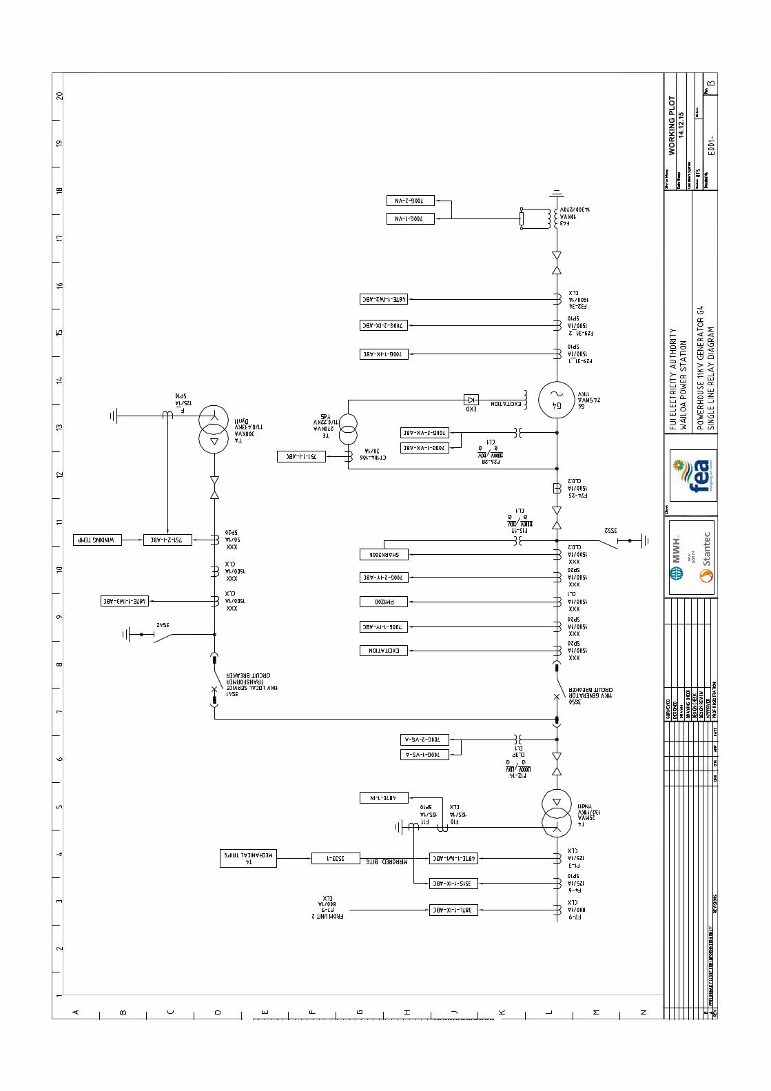
WO
RK
ING
PLO
T14
.12.
15
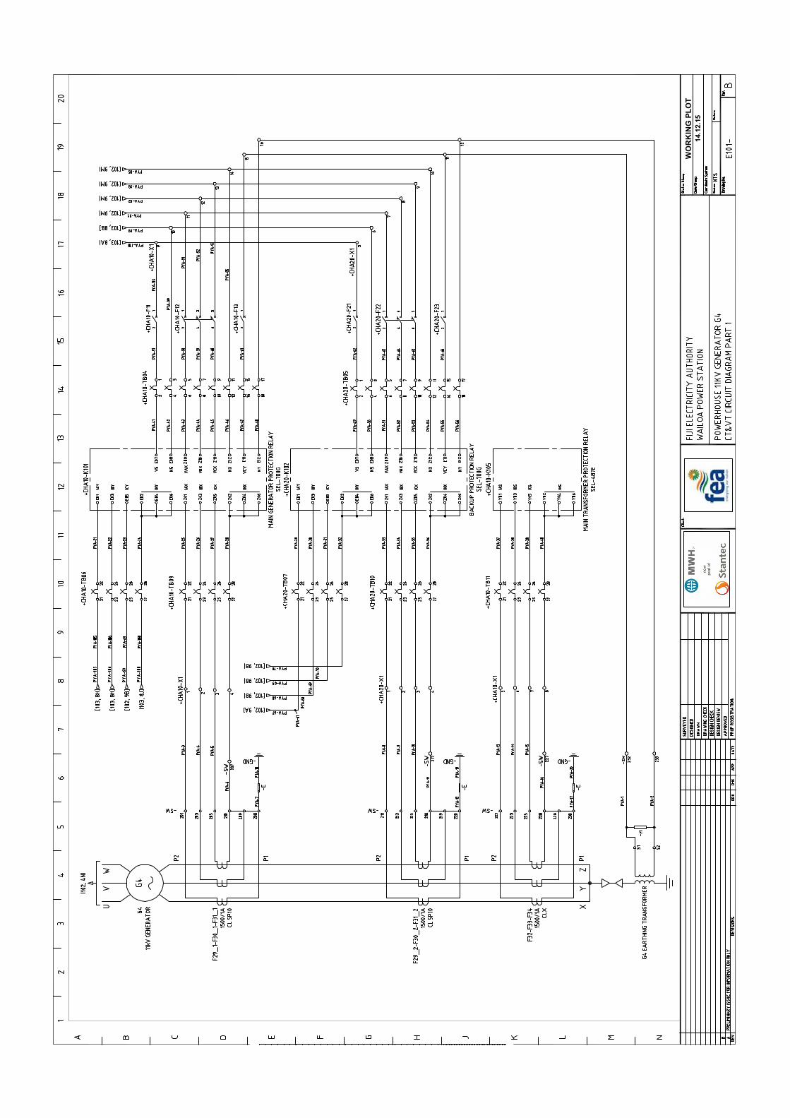
WO
RK
ING
PLO
T14
.12.
15

WO
RK
ING
PLO
T14
.12.
15

WO
RK
ING
PLO
T14
.12.
15

WO
RK
ING
PLO
T14
.12.
15

WO
RK
ING
PLO
T14
.12.
15
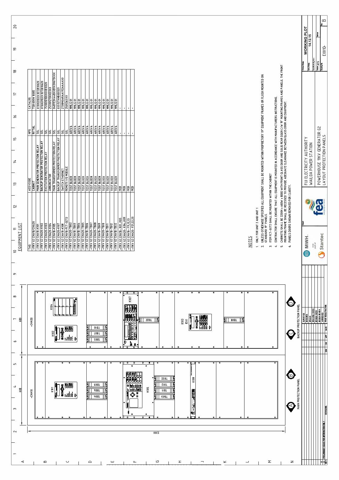
–
–
WO
RK
ING
PLO
T14
.12.
15

REMOTE I/O MODULE
SEL-
2505
LABORATORIES
ENGINEERING
SCHWEITZER
WO
RK
ING
PLO
T14
.12.
15

WO
RK
ING
PLO
T14
.12.
15
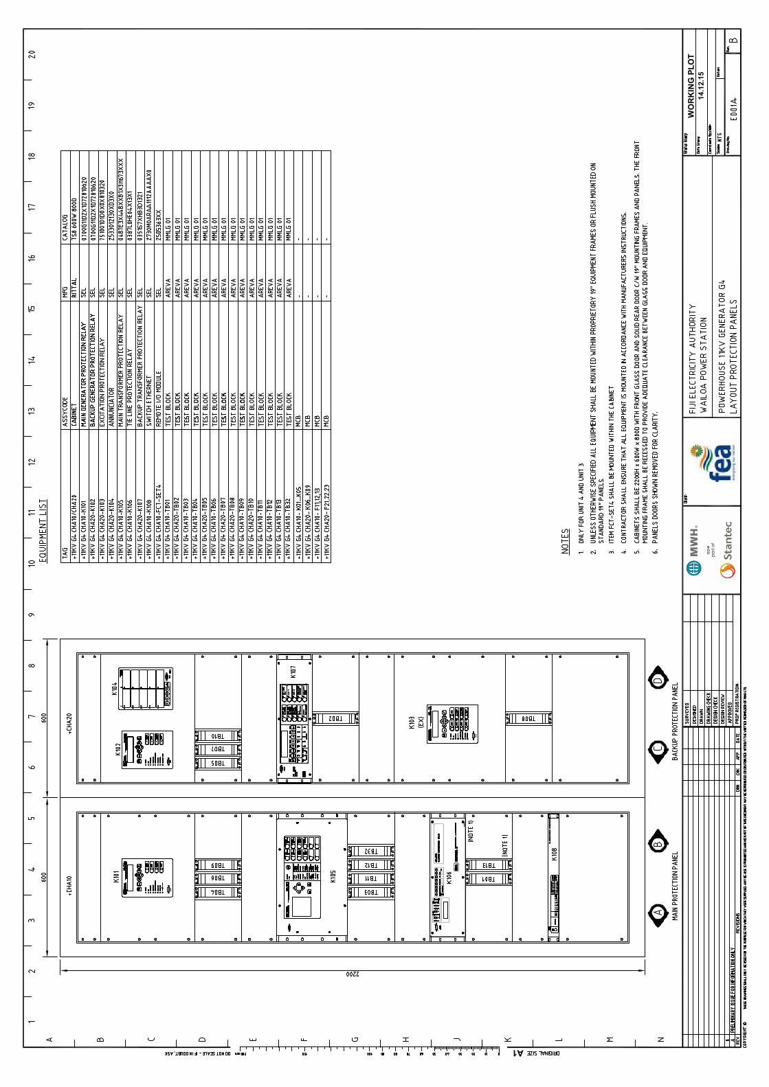
–
–
A1
WO
RK
ING
PLO
T14
.12.
15

REMOTE I/O MODULE
SEL-
2505
LABORATORIES
ENGINEERING
SCHWEITZER
A1
WO
RK
ING
PLO
T14
.12.
15

WO
RK
ING
PLO
T14
.12.
15
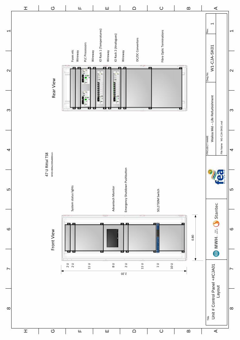
87
65
43
21
H G F E D C B A
87
65
43
21
H G F E D C B A
Title Uni
t # C
ontro
l Pan
el +
#CJA
01
Layo
utFi
le N
ame
W1-
CJA
-SK
01.v
sd
PR
OJE
CT
NAM
E
Wai
loa
Mid
– L
ife R
efur
bish
men
tD
wg.
No.
W1-
CJA
-SK
01R
ev.
1
4 U
PLC Processors
2 U
System
status lights
2 U
8 U
Advantech Mon
itor
1 U
SEL273
0M Switch
2.20
0.80
10 U
HPv18
5wAu
toMen
u
2 U
Emergency Shutdo
wn Pu
shbu
tton
11 U
11 U
47 U Rittal TS8
WHD=
800x2200x800mm
2 U
Wire
way
2 U
Fuses etc
2 U
Wire
way
4 U
IO Rack 1 (Tem
peratures)
2 U
Wire
way
4 U
IO Rack 2 (Analogues)
2 U
Wire
way
10 U
DC/DC Co
nvertors
12 U
Fibre Optic Terminations
Fron
t View
Rear View

87
65
43
21
H G F E D C B A
87
65
43
21
H G F E D C B A
Title Uni
t # C
ontro
l Pan
el +
#CJA
02
Layo
utFi
le N
ame
W1-
CJA
-SK
02.v
sd
PR
OJE
CT
NAM
E
Wai
loa
Mid
– L
ife R
efur
bish
men
tD
wg.
No.
W1-
CJA
-SK
02R
ev.
1
4 U
IO Rack 3 (Digita
ls)
9 U
2.20
0.80
5 U
Multifun
ction Meter, M
anual synchroniser
& con
trols
47 U Rittal TS8
WHD=
800x2200x800mm
2 U
Wire
way
2 U
Fuses etc
2 U
Wire
way
4 U
IO Rack 4 (Digita
ls)
2 U
Wire
way
10 U
DC/DC Co
nvertors
19 U
Relays
5 U
Energy M
eters
5 U
Trip Relays 8
6A and
86B
18 U
Fron
t View
Rear View
4 U
Meter Test B
locks

87
65
43
21
H G F E D C B A
87
65
43
21
H G F E D C B A
Title
Uni
t 1 P
LC A
rchi
tect
ure
Shee
t 1
File
Nam
eW
0-C
JA-S
K03
.vsd
PR
OJE
CT
NAM
E
Wai
loa
Mid
– L
ife R
efur
bish
men
tD
wg.
No.
W1-
CJA
-SK
03R
ev.
1

87
65
43
21
H G F E D C B A
87
65
43
21
H G F E D C B A
Title
Uni
t 1 P
LC A
rchi
tect
ure
Shee
t 2
File
Nam
eW
0-C
JA-S
K04
.vsd
PR
OJE
CT
NAM
E
Wai
loa
Mid
– L
ife R
efur
bish
men
tD
wg.
No.
W1-
CJA
-SK
04R
ev.
1

87
65
43
21
H G F E D C B A
87
65
43
21
H G F E D C B A
Title
Uni
t 1 T
rippi
ng S
chem
e
File
Nam
eW
0-C
JA-S
K05
.vsd
PR
OJE
CT
NAM
E
Wai
loa
Mid
– L
ife R
efur
bish
men
tD
wg.
No.
W1-
CJA
-SK
05R
ev.
1
132kV Tie Line
Protectio
nSEL387L ‐K106
Unit 1
86A
Lockou
t Re
lay
132kV CB
Trip Coil 1
Hardwire
d Trips 1
Main
Transformer
Main Protectio
nSEL487
E ‐K105
Main
Transformer
Mechanical
Trips
SEL2533 ‐K104
Unit 3
86A
Excitatio
nTransformer
Protectio
nSEL751
‐K103
Unit 1
PLC
Brake Jet
Gen
erator M
ain
Protectio
nSEL700G ‐K
101
Gen
erator
Backup
Protectio
nSEL700G ‐K
102
Main
Transformer
Backup
Protectio
nSEL351S ‐K107
Unit 1
86B
Lockou
tRe
lay
“Mechanical”
Trips
Inlet V
alve
Close 1
Gov
Shutdo
wn 1
Excitatio
n Trip 1
GCB
Trip 1
Inlet V
alve
Close 2
Gov
Shutdo
wn 2
Excitatio
n Trip 2
GCB
Trip 2
Hardwire
d Trips 2
Mirror bits
Via SEL2505
‐ Estop
(Governo
r panel)
‐ Estop
(Con
trol Pan
el)
‐ Estop
(NCC
)‐ O
verspe
ed (M
echanical)
‐ PLC W
atchdo
g‐ G
overno
r Watchdo
g‐ Statio
n Floo
ded
‐ Estop
(Governo
r panel)
‐ Estop
(Con
trol Panel)
‐ Estop
(NCC
)‐ O
verspe
ed (E
lectric
al)
‐ Governo
r Oil Pressure
Low
= Eq
uipm
ent In Main Protectio
n Panel
= Equipm
ent In Ba
ckup
Protection Pane
l
= Eq
uipm
ent In PLC Pane
l
Mechanical Trip
sInitiating Co
ndition
Unloade
dEm
ergencyBraking
Estop at Governo
rX
Estop at Con
trol Panel
XPenstock Pressure Ab
norm
alX
Inlet V
alve Not Open
XTurbine Distrib
utor Pressure Low
XTurbine Bearing Oil Level A
bnormal
XTurbine Bearing Oil Temperature High
XX
Turbine Bearing Metal Tem
perature High
XX
Turbine Bearing Co
oling Water Flow Fail
XX
Turbine Bearing Co
oling Water Tem
perature High
XX
Turbine Bearing Vibration High
XX
Mechanical O
verspeed
XX
Governo
r Oil Temperature High
XGoverno
r Fault
XGoverno
r Accum
ulator Pressure Ab
norm
alX
Governo
r HPU
Pressure Low
XGoverno
r HPU
Tem
perature High
XExcitatio
n Trip
XExcitatio
n Transformer Tem
perature High
XElectrical Overspeed
XStator W
inding
Tem
perature High
XGenerator Coo
ler A
ir Temperature High
XGenerator Coo
ler W
ater Tem
perature High
XGenerator Bearin
g Oil Level A
bnormal
XGenerator Bearin
g Oil Temperature High
XX
Generator Bearin
g Metal Tem
perature High
XX
Generator Bearin
g Co
oling Water Flow Fail
XX
Generator Bearin
g Co
oling Water Tem
perature High
XX
Generator Bearin
g Vibration High
XX
Generator HP Oil System
Fail
XX

87
65
43
21
H G F E D C B A
87
65
43
21
H G F E D C B A
Title
Con
trol S
yste
m A
rchi
tect
ure
File
Nam
eW
0-C
KA-S
K01.
vsd
PR
OJE
CT
NAM
E
Wai
loa
Mid
– L
ife R
efur
bish
men
tD
wg.
No.
W1-
CK
A-S
K01
Rev
.
1

87
65
43
21
H G F E D C B A
87
65
43
21
H G F E D C B A
Title Pr
otec
tion
Sys
tem
Com
mun
icat
ions
Ar
chite
ctur
eFi
le N
ame
W0-
CKA
-SK0
2.vs
d
PR
OJE
CT
NAM
E
Wai
loa
Mid
– L
ife R
efur
bish
men
tD
wg.
No.
W1-
CK
A-S
K02
Rev
.
1

MR69/2017 Wailoa Mid-Life Refurbishment Control and Protection Panel Supply
Status – For Tender Page 58 March 2017 Project Number – 80508617 Tender MR69-2017_R1
Appendix B Common Requirements Specification

Fiji Electricity Authority
Wailoa Mid-Life Refurbishment Project Common Requirements
June 2016
Fiji Electricity Authority Wailoa Mid-Life Refurbishment Project
Common Requirements
Status Final Apr 2016
Project Number 80507610 Our Ref − Wailoa Mid-Life Refurbishment Common Requirements_R1
Contents 1 Design Requirements.............................................................................................................. 1
1.1 Design Responsibility ........................................................................................ 1
1.2 Project Procedures ............................................................................................ 1
1.3 Submittals ........................................................................................................ 1 1.3.1 Drawing Standards ....................................................................................... 3 1.3.2 Outline Drawings .......................................................................................... 3 1.3.3 Detail Drawings ............................................................................................ 3 1.3.4 Line Diagrams.............................................................................................. 4 1.3.5 Schematic/Elementary Diagrams ................................................................... 4 1.3.6 Wiring Diagrams........................................................................................... 4 1.3.7 Panel Layouts .............................................................................................. 4 1.3.8 Nameplate Schedules, Meter Scales, Engravings and Switch Handles.............. 4 1.3.9 Design Calculations ...................................................................................... 4 1.3.10 Bills of Material............................................................................................. 5 1.3.11 Cable Schedules .......................................................................................... 5 1.3.12 Pipe Schedules ............................................................................................ 5 1.3.13 Functional Block Diagrams ............................................................................ 5 1.3.14 Block diagrams shall be provided that show the functional configuration of the
main components of a system including the communication network and paths interconnecting them. The functional block diagram shall be presented in a manner that conveys the functionality of the system. Termination Drawings/Schedules ..................................................................................... 5
1.3.15 Logic Diagrams ............................................................................................ 5 1.3.16 Erection Schedule ........................................................................................ 6 1.3.17 Instructions .................................................................................................. 6 1.3.18 Operating and Maintenance Instructions......................................................... 7 1.3.19 Field Commissioning Procedures of Check-Out, Start-Up, Initial Operation,
Testing and Test Run ..................................................................................10 1.3.20 Reports 10 1.3.21 Photographs ...............................................................................................10
1.4 Quality Control & Testing Plans .........................................................................11 1.4.1 Witnessing of Shop Assembly and Tests .......................................................11 1.4.2 Factory Tests ..............................................................................................12
Fiji Electricity Authority Wailoa Mid-Life Refurbishment Project Common Requirements

Fiji Electricity Authority Wailoa Mid-Life Refurbishment Project
Common Requirements
Status Final Apr 2016
Project Number 80507610 Our Ref − Wailoa Mid-Life Refurbishment Common Requirements_R1
1.4.3 Test and Commissioning Plan ......................................................................12 1.4.4 Training Program ........................................................................................12 1.4.5 Materials 12 1.4.6 Supplier Information ....................................................................................12 1.4.7 Purchase Orders .........................................................................................13 1.4.8 Spare Parts Lists .........................................................................................13 1.4.9 Notice(s) of Equipment Inspections ...............................................................13 1.4.10 Shop Inspection and Test Reports ................................................................13 1.4.11 Quality Control Reports ................................................................................13 1.4.12 Manufacturer Field Service Reports ..............................................................13 1.4.13 As-Built Drawings ........................................................................................13
1.5 Drawings Furnished by the Employer .................................................................13
1.6 Units of Measurement .......................................................................................14
1.7 Site Conditions .................................................................................................14 1.7.1 General Conditions ......................................................................................14 1.7.2 Transport Limitations ...................................................................................14 1.7.3 Water Conditions and Corrosion ...................................................................14
1.8 Spare Parts .....................................................................................................15 1.8.1 Specified Spare Parts ..................................................................................15 1.8.2 Optional Spare Parts and Maintenance Equipment .........................................15
1.9 Tools and Appliances .......................................................................................15
1.10 Labels and Plates .............................................................................................15
1.11 Standards ........................................................................................................16 1.11.1 Australian/New Zealand Standards ...............................................................17 1.11.2 International Electrotechnical Commission (IEC) ............................................17 1.11.3 American National Standards Institute (ANSI) ................................................19 1.11.4 Institute of Electrical and Electronic Engineers (IEEE).....................................19 1.11.5 British Standards (BS) .................................................................................19 1.11.6 ASTM 20 1.11.7 Other 20
2 Mechanical Requirements ......................................................................................................22
2.1 Workmanship ...................................................................................................22
2.2 Handrails .........................................................................................................22
2.3 Materials .........................................................................................................22
2.4 Test of Materials...............................................................................................24 2.4.1 General 24 2.4.2 Impact and Bend Tests ................................................................................24 2.4.3 Test Certificates ..........................................................................................24
2.5 Safety Factors and Design Stresses ..................................................................25 2.5.1 General 25 2.5.2 Maximum Allowable Stresses .......................................................................25

Fiji Electricity Authority Wailoa Mid-Life Refurbishment Project
Common Requirements
Status Final Apr 2016
Project Number 80507610 Our Ref − Wailoa Mid-Life Refurbishment Common Requirements_R1
2.6 Tolerances.......................................................................................................25
2.7 Workmanship ...................................................................................................26
2.8 Welding ...........................................................................................................26 2.8.1 General 26 2.8.2 Edge Preparation ........................................................................................26 2.8.3 Welding Qualifications .................................................................................26 2.8.4 Field-Weld-Filler Metal .................................................................................27 2.8.5 Documentation ............................................................................................27
2.9 Fabrication.......................................................................................................27
2.10 Non-destructive Testing ....................................................................................27 2.10.1 General 27 2.10.2 Examination of Welds ..................................................................................27 2.10.3 Examination of Castings ..............................................................................28 2.10.4 Examination of Forgings ..............................................................................28
2.11 Steel Castings..................................................................................................28 2.11.1 General 28 2.11.2 Inspection ...................................................................................................29 2.11.3 Repair Welding ...........................................................................................29 2.11.4 Dimensions.................................................................................................29
2.12 Surface Finish of Equipment Parts and Welds.....................................................30 2.12.1 Weld Finish.................................................................................................30 2.12.2 Hydraulic Packing........................................................................................30 2.12.3 Auxiliary Equipment and Data.......................................................................30 2.12.4 Nameplates ................................................................................................30
2.13 Piping..............................................................................................................31 2.13.1 General 31 2.13.2 Water Piping ...............................................................................................31 2.13.3 Oil Piping ....................................................................................................32 2.13.4 Piping Integral with Turbine Water Passages .................................................32 2.13.5 Piezometer and Pressure Tap Piping ............................................................32 2.13.6 Compressed Air Piping ................................................................................32 2.13.7 Instrument Piping ........................................................................................32 2.13.8 Governor and Inlet Valve Oil Pressure Piping.................................................32 2.13.9 Carbon Dioxide Piping .................................................................................33 2.13.10 Pipe Supports and Piping Materials...............................................................33 2.13.11 Piping Connections......................................................................................33
2.14 Pumps.............................................................................................................33
2.15 Foundation Materials ........................................................................................35 2.15.1 General 35 2.15.2 Design 35 2.15.3 Anchor Bolts ...............................................................................................35
2.16 Handling Devices .............................................................................................35
Fiji Electricity Authority Wailoa Mid-Life Refurbishment Project
Common Requirements
Status Final Apr 2016
Project Number 80507610 Our Ref − Wailoa Mid-Life Refurbishment Common Requirements_R1
2.17 Protection, Cleaning and Painting ......................................................................36 2.17.1 General 36 2.17.2 Employers Colour Scheme ...........................................................................37 2.17.3 Surface Preparation.....................................................................................38 2.17.4 Application Procedure ..................................................................................38 2.17.5 Surfaces Not to be Painted...........................................................................38 2.17.6 Galvanising.................................................................................................38 2.17.7 Paint Schedule ............................................................................................39
2.18 Lubricants and Hydraulic Fluid...........................................................................39
2.19 Ventilation and Air Condit ioning Systems............................................................40 2.19.1 Ductwork 40 2.19.2 Fans 43
3 Electrical Requirements .........................................................................................................46
3.1 General ...........................................................................................................46
3.2 System Conditions ...........................................................................................46
3.3 Phase Rotation ................................................................................................46
3.4 Control Equipment Electrical Ratings .................................................................46 3.4.1 Voltage Ratings...........................................................................................46 3.4.2 Electrical Contact Ratings ............................................................................47
3.5 Motors .............................................................................................................47 3.5.1 Standards ...................................................................................................47 3.5.2 Ratings and Characteristics ..........................................................................47 3.5.3 Service Factor.............................................................................................47 3.5.4 Bearings 48 3.5.5 Starting 48 3.5.6 Finish 48
3.6 Cabling Installation Practice ..............................................................................48 3.6.1 General 48 3.6.2 Cable Identification ......................................................................................49 3.6.3 Underground Cables....................................................................................49 3.6.4 Cable Ladder ..............................................................................................49 3.6.5 Cable Installat ion Practice (HV Cables) .........................................................50 3.6.6 Cabling Installation Practice (LV Cables) .......................................................50 3.6.7 Cable Installat ion Practice (Instrumentation Cables) .......................................51
3.7 Cable Selection ................................................................................................52 3.7.1 240/415V Cables.........................................................................................52 3.7.2 Instrumentation Cabling ...............................................................................52 3.7.3 Control Cabling ...........................................................................................53
3.8 Earthing and Equipotential Bonding ...................................................................53 3.8.1 Building Structure ........................................................................................53 3.8.2 External Foundation Pads ............................................................................53 3.8.3 External Fencing .........................................................................................53

Fiji Electricity Authority Wailoa Mid-Life Refurbishment Project
Common Requirements
Status Final Apr 2016
Project Number 80507610 Our Ref − Wailoa Mid-Life Refurbishment Common Requirements_R1
3.9 Panel Construction ...........................................................................................54 3.9.1 Metalwork ...................................................................................................54 3.9.2 Terminals ...................................................................................................54 3.9.3 Neutral & Earth Bars ....................................................................................55 3.9.4 Busbars & Connections................................................................................55 3.9.5 Fuses 55 3.9.6 Miniature Circuit Breakers (MCBs) ................................................................56 3.9.7 Moulded Case Circuit Breakers (MCCBs) ......................................................56 3.9.8 Relays 56 3.9.9 Contactors ..................................................................................................56 3.9.10 Isolators 57 3.9.11 Pushbuttons and Pushbutton Switches..........................................................57 3.9.12 Control and Selector Switches ......................................................................57 3.9.13 Electrical Digital and Analogue Indicating Instruments ....................................58 3.9.14 Motor Starters .............................................................................................59 3.9.15 Heaters 60 3.9.16 Lighting and Receptacles .............................................................................61 3.9.17 Panel Wiring ...............................................................................................61 3.9.18 Panel Earthing ............................................................................................62 3.9.19 Panel Labelling ...........................................................................................62
3.10 Small Power requirements ................................................................................63 3.10.1 Outlet Boxes ...............................................................................................63 3.10.2 Receptacles and Switches ...........................................................................63 3.10.3 Fixtures 63 3.10.4 Ballasts 64 3.10.5 Lamps 64 3.10.6 Lighting Panel Boards ..................................................................................64 3.10.7 Lighting Contactor Cabinets .........................................................................64 3.10.8 Photocells...................................................................................................64
3.11 Switchboards ...................................................................................................64 3.11.1 General 64 3.11.2 Metalwork ...................................................................................................65 3.11.3 Construction ...............................................................................................65 3.11.4 Busbars and Connections ............................................................................65 3.11.5 Neutral & Earth Bars ....................................................................................66 3.11.6 Moulded Case Circuit Breakers (MCCBs) ......................................................66 3.11.7 Miniature Circuit Breakers (MCBs) ................................................................68 3.11.8 Cable Details ..............................................................................................69 3.11.9 Contactors ..................................................................................................69 3.11.10 Control Relays ............................................................................................69 3.11.11 Control Wiring .............................................................................................69 3.11.12 Selector Switches ........................................................................................70 3.11.13 Terminals – Control Wiring ...........................................................................70 3.11.14 Earthing 70 3.11.15 Labels 70 3.11.16 Manufacture................................................................................................71

Fiji Electricity Authority Wailoa Mid-Life Refurbishment Project
Common Requirements
Status Final Apr 2016
Project Number 80507610 Our Ref − Wailoa Mid-Life Refurbishment Common Requirements_R1
3.12 Distribution Boards ...........................................................................................71 3.12.1 General 71 3.12.2 Cabinet Construction ...................................................................................71 3.12.3 Busbars & Connections................................................................................72 3.12.4 Circuit Breakers ..........................................................................................72 3.12.5 Isolators 72 3.12.6 Manufacture................................................................................................72
3.13 Battery Charger Panel Construction ...................................................................72 3.13.1 Control Panel Terminals...............................................................................73 3.13.2 Fuses 73 3.13.3 Relays 73

Fiji Electricity Authority Wailoa Mid-Life Refurbishment Project
Common Requirements
Status Final Page 1 Apr 2016 Project Number 80507610 Our Ref − Wailoa Mid-Life Refurbishment Common Requirements_R1
1 Design Requirements
1.1 Design Responsibility
The Contractor shall assume full responsibility for a coordinated and adequate design of all equipment specified and shall ensure that such equipment conforms to the best engineering practice for the operating conditions specified. When requested by the Engineer, the Contractor shall furnish complete information as to the maximum stresses and other criteria used in the design. All equipment shall be proportioned and arranged to fit with proper clearances into the nominated spaces.
1.2 Project Procedures
The Contractor shall issue a set of Project Procedures within 28 days from the Commencement Date for Engineer's review and approval. Such document shall give the procedures which shall govern the relationship between Employer and Contractor, document distribution, lines of communication (including contact information), responsibility of project participants, etc.
1.3 Submittals
The following drawings and document listing is intended to summarize the information and data to be submitted by the Contractor to the Engineer. In the case of differences between this list and the specific submittal descriptions of the Employer’s Requirements, or the Particular Conditions of Contract, the specific descriptions or particular conditions shall govern. Table 1.1
Document Submittal Schedule Submitted for A. Basic Design Drawings All documents as detailed in the “Basic Design” section of the Technical Specification.
Note 2 Review/Approval
B. Detailed Design All documents as detailed in the “Detailed Design” section of the Technical Specification.
Note 2 Review/Approval
C. Other Documents Quality control plan Within 10 days of
Commencement Review/Approval
Contractor progress reports Monthly Materials test certificates As received. Info/Record QA/QC procedures Shop test/inspection reports
Note 2 Review/Approval Review/Approval

Fiji Electricity Authority Wailoa Mid-Life Refurbishment Project
Common Requirements
Status Final Page 2 Apr 2016 Project Number 80507610 Our Ref − Wailoa Mid-Life Refurbishment Common Requirements_R1
Document Submittal Schedule Submitted for On completion of each test/inspection
Operating and Maintenance Manuals Note 3 Review/Approval Field Commissioning Procedures Note 4 Review/Approval Shop drawings Note 2 Info/Record As-Built design drawings Note 2 Info/Record Recommended spare parts and maintenance equipment list
Note 2
Review
Notes: 1. Submittals
a. ''Info/Record“ refers to documentation that normally will not be reviewed by Engineer during the design phase but is required for the testing, commissioning and operation phase.
b. “Review” refers to documents that Engineer will receive and comment on during the design, construction or testing, commissioning and testing phase, as applicable.
c. ''Approval“ refers to documents Engineer shall approve or give acceptance as set forth in the Contract. d. If documents are required earlier to support Engineer related activities such as: permitting interface with
other Employer contractors' activities, etc., Contractor shall use all reasonable efforts to support these requirements.
2. Design Drawings and Documents
a. The Basic Design provided with the Tender shall be updated and issued as follows: (1) Issue for comments from the Engineer (2) Engineer comment period is 14 days (3) Incorporate comments and issue for final review within 14 days (4) Engineer's final review period is 14 days (5) Basic Design issued within 14 days.
b. Detailed Design to be issued as follows:
(1) Issue for comments from the Engineer (2) Engineer comment period is 14 days (3) Incorporate comments and issue for Construction (4) Engineer will comment again if necessary and the Contractor will revise the document if required.
c. Design drawings and documents shall be transmitted to Engineer upon issuance of the drawing/document, or any revision thereof, or when “Issued for Construction“ or “issued for Manufacture”.
d. Shop drawings and documents to be transmitted to Engineer for “Info/Record“ shall be transmitted to Engineer within 1 month after shipment of the plant to which the Shop drawing relates.
e. As Built or As Constructed drawings and documents to be transmitted to Engineer for “Info/Record“ shall be transmitted to Engineer on within 2 weeks after shipment of the plant to which the As Built drawing relates or within one month after construction is completed. Red pen markups of all

Fiji Electricity Authority Wailoa Mid-Life Refurbishment Project
Common Requirements
Status Final Page 3 Apr 2016 Project Number 80507610 Our Ref − Wailoa Mid-Life Refurbishment Common Requirements_R1
construction drawings showing any site modifications shall be retained on site until such time as the As Constructed records have been delivered.
3. Operating and Maintenance manuals shall be provided 4 weeks prior to ex works shipment of the plant to which the Operating and Maintenance manuals relates.
4. Field Commissioning Procedures shall be provided 3 months prior to the field testing and commissioning of the plant to which the Field Commissioning Procedures relates.
1.3.1 Drawing Standards
All drawings shall be prepared in accordance with ISO standards, and shall be based on the “A” series paper sizes as defined in ISO216.
Electrical drawings shall use the IEC symbol set as defined in IEC 60617. P&ID drawings shall use the symbol set defined in the Instrument Society of America standard S5.1. Electronic master files of all drawings shall be provided in Autocad DWG format. Each dwg file shall only contain one drawing sheet and shall have a unique file number that matches the number on the drawing sheet. The electronic file shall be saved such that, upon opening, the full drawing is depicted on the screen and the “Print Extents” command will print the entire drawing correctly aligned on the paper. All drawings shall include the following:- • Drawing title. • Logo for the Employer, Engineer and Contractor. • Original drawing size. • Revision Index. • Quality control verification for checked and approved. • Space for Employers Approval. • Drawing number using the Employers drawing numbering system.
All modifications made to a drawing shall be “clouded” and marked with the revision identification. Previous revision clouding shall be removed.
1.3.2 Outline Drawings
Outline drawings shall be drawn to scale and denoted with critical or major dimensions. Drawings shall include estimated weights, external forces, anchoring details and overall dimensions and information on installation requirements for the equipment.
1.3.3 Detail Drawings
Detail drawings shall consist of general assembly Drawings, subassembly Drawings and details to demonstrate fully that all parts will conform to the provisions and intent of the Employer’s Requirements and to the requirements of their installation, operation and maintenance.

Fiji Electricity Authority Wailoa Mid-Life Refurbishment Project
Common Requirements
Status Final Page 4 Apr 2016 Project Number 80507610 Our Ref − Wailoa Mid-Life Refurbishment Common Requirements_R1
1.3.4 Line Diagrams
• Electrical Single line diagrams showing the power connections, location of instrument and control transformers, and connections to transducers, meters, relays and instruments.
• Single line relay diagrams. Expanded single line diagrams showing all protective relay elements and tripping paths.
• Process and Instrumentation Diagrams (P&IDs) for all systems.
1.3.5 Schematic/Elementary Diagrams
Diagrams shall demonstrate the operation of the supplied control equipment. They shall include: • Electrical schematic drawings showing each individual component, terminal, interconnecting wiring,
associated terminal, conductor and cable identification; protective device ratings and settings; voltage levels.
Electrical schematic drawings shall be ladder style drawing to DIN standards, including an ‘assembled form’ depiction of each element with references identifying the drawing sheet on which each terminal is used.
1.3.6 Wiring Diagrams
Diagrams shall show the point-to-point interconnections of the control and power equipment. Control devices and terminal blocks shall be shown in their correct relative positions. One side of the terminal blocks shall be clearly identified for external wiring connections and shall be free of any manufacturer's wiring. Control devices and terminal blocks shall be identified in accordance with schematic/elementary diagrams.
1.3.7 Panel Layouts
Equipment and nameplates mounted on and within control cabinets and switchboards shall be shown. Diagrams shall be drawn to scale.
1.3.8 Nameplate Schedules, Meter Scales, Engravings and Switch Handles
Schedules for all front-of-panel devices and equipment shall be provided. Nameplate schedules shall include dimensions and lettering size. Scale markings for meters and other indicating instruments shall be shown. Escutcheon plate and legend plate engravings and type and color of switch handles shall be shown.
1.3.9 Design Calculations
The design calculations shall define the design approach, assumptions, criteria used and the calculated results in sufficient detail to demonstrate that the equipment meets the specified requirements and to provide adequate information for trouble-shooting of the equipment.

Fiji Electricity Authority Wailoa Mid-Life Refurbishment Project
Common Requirements
Status Final Page 5 Apr 2016 Project Number 80507610 Our Ref − Wailoa Mid-Life Refurbishment Common Requirements_R1
1.3.10 Bills of Material
A list of equipment shall be submitted for each major assembly or sub-assembly and shall include the names of manufacturers of articles and auxiliary equipment to be incorporated in the work, together with description, part number, ratings, performance characteristics and other significant information as necessary to allow the Employer to obtain replacement parts. A separate list of equipment shall be provided for each printed circuit board and sub-assembly incorporated into the work, identifying the individual components mounted on the board. Bills of Material shall be provided listing the spare parts, special tools and maintenance equipment.
1.3.11 Cable Schedules
Tabulations showing the routing of all cable and wire used for power, control and instrumentation circuits shall be provided. Cable tabulations shall be prepared showing the type, size and number of conductors in each cable. Each cable shall be given a unique cable identifier. The cable tabulations shall list the equipment to which each cable is connected (From/To) and the cable tray in which it is routed.
1.3.12 Pipe Schedules
Tabulations showing the routing of all piping shall be provided. Pipe tabulations shall be prepared showing the material, size, pressure and conveyed material of each pipe. Each pipe shall be given a unique pipe identifier. The pipe tabulations shall list the equipment to which each pipe is connected (From/To) and the pipe rack in which it is routed.
1.3.13 Functional Block Diagrams
1.3.14 Block diagrams shall be provided that show the functional configuration of the main components of a system including the communication network and paths interconnecting them. The functional block diagram shall be presented in a manner that conveys the functionality of the system. Termination Drawings/Schedules
All terminations of power, control and instrumentation cable external to an electrical component, panel or cabinet shall be shown either on termination drawings or on schedules. Information shall include the terminal block designation, cable identifier, cable characteristics (i.e., size, number conductors/pairs/triads, shielding) conductor identification (e.g., number, color), number of spare conductors and to where the other end of the cable is routed (with references).
1.3.15 Logic Diagrams
1.3.15.1 General A complete set of logic diagrams describing the software used in microprocessor-based controllers shall be provided. The logic diagrams shall be provided as follows: • Analog Control Loops. These diagrams shall be provided in accordance with ISA standard format.

Fiji Electricity Authority Wailoa Mid-Life Refurbishment Project
Common Requirements
Status Final Page 6 Apr 2016 Project Number 80507610 Our Ref − Wailoa Mid-Life Refurbishment Common Requirements_R1
• Sequencing Controls. Controls used for sequencing logic shall be provided in Boolean or ladder-type format.
Logic diagrams shall be drawing in accordance with IEC 61131-3.
1.3.15.2 Software Software updates or enhancements shall be supplied to the Employer at no charge within two (2) years after the last delivery of the equipment. After this period, updates shall be made available to the Employer at a negotiated fee.
1.3.16 Erection Schedule
A detailed erection schedule shall be prepared and submitted to the Engineer showing the estimated time needed for installation and listing the type and number of personnel and tools required by the Contractor. The schedule shall be submitted not later than two (2) months prior to delivery of the first piece of equipment. The schedule shall include the time required for field erection, installation, check-out, start-up, initial operation, testing and test run.
1.3.17 Instructions
1.3.17.1 General The Contractor shall submit written detailed instructions for factory assembly and testing; handling and storage; installation, operating and maintenance and field commissioning procedures of check-out, start-up, initial operation, testing and test run for each item of equipment. The instructions shall be submitted as early as possible so that final reviewed copies can be made available to the field for use in planning their work well in advance of actual installation and operation. After review, ten (10) complete, durable bound copies of the final instructions shall be furnished.
1.3.17.2 Shop Assembly and Testing Procedure A step-by-step procedure shall be submitted outlining the details of the checks to be made before and after factory assembly and testing of the equipment to demonstrate that the requirements of these Employer’s Requirements and other parts of the Contract have been fulfilled. The factory assembly and testing procedure shall be submitted in a tabular form itemizing each test, indicating the results expected in accordance with the design and leaving space for the actual observation during assembly and testing. The test procedures shall include test values to be used, maximum/minimum acceptable test results and reference to accepted industry standards. The limitations, if any, of the factory tests shall be fully explained and shall be approved by the Engineer.
1.3.17.3 Handling and Storage Instructions Detailed instructions, with illustrations, diagrams and weights, for handling, storage and care of equipment at the site shall be submitted. The instructions shall include:

Fiji Electricity Authority Wailoa Mid-Life Refurbishment Project
Common Requirements
Status Final Page 7 Apr 2016 Project Number 80507610 Our Ref − Wailoa Mid-Life Refurbishment Common Requirements_R1
• Identification of parts requiring special outdoor, indoor or temperature or humidity-controlled storage for both long- and short-term storage;
• Space requirements for outdoor, indoor and temperature- or humidity-controlled storage for both long-term and short-term storage;
• The procedures to be observed in unloading, placing, stacking and blocking of equipment; • Rigging and lifting procedures; • Maintenance procedures for both long- and short-term storage including maximum recommended
storage period for items stored outdoors; • Periodic rotation of components, where required; • Application of protective coatings; and • Cleaning of protective coatings and/or corrosion prior to installation.
1.3.17.4 Installation Instructions Detailed instructions for the installation of the equipment shall be submitted together with reduced-size copies of applicable Drawings showing the erection sequence. The instructions and Drawings shall include information on handling and slinging the major pieces of equipment including weights, erection tolerances and special precautions to be observed during installation.
1.3.18 Operating and Maintenance Instructions
2.1.1.1.1 General
The Contractor shall provide sets of well structured, comprehensive and coordinated manuals to fully describe all aspects of design, operating and maintenance of all plant, equipment and systems provided under the Contract.
The Contractor shall arrange his manuals in three separate parts, namely Design, Operation and Maintenance. The layout of each part should, as far as possible, be consistent throughout each of the three parts, with systems, plant and plant described in the same order in each section. Each section shall be divided into as many volumes as necessary for convenient handling and reference.
Comprehensive indexing and cross-referencing shall be included to ensure easy access to information as required. A master index covering all three parts of the manuals shall be included in each volume, in addition to the detailed index for the particular section. PDF manuals shall include bookmarks and hyperlinks to facilitate navigation through the manual.
The manual format shall be on standard metric A4 sheets. Drawings and schedules, which are to be bound into the manual, shall be either A4 or A3 folded to A4.
Manuals from all sub-contractors shall be written in the same format.
The manuals shall include instructions only for the actual plant supplied and not for alternative or optional plant. For instance, a pump may have several different shaft sealing systems, but reference shall be made only to the system supplied.

Fiji Electricity Authority Wailoa Mid-Life Refurbishment Project
Common Requirements
Status Final Page 8 Apr 2016 Project Number 80507610 Our Ref − Wailoa Mid-Life Refurbishment Common Requirements_R1
All plant identification shall be by means of description and numbering systems specific to the Project as approved by the Employer.
Three hardcopy, and one pdf electronic copy of each manual shall be provided.
2.1.1.1.2 Scope of Manuals
The information to be provided in the manuals shall include, but not be limited to, the material listed in the following sections. They shall provide all necessary information for plant and procedures.
Design Manuals The volume(s) comprising the design part of the manual should be laid out as follows:-
• Preliminary pages including index, preface, amendment record sheet and illustration of the complete plant. • General description of the system including:-
− System diagrams and block diagrams showing sub-systems and interconnection with other systems. − System description, including design basis, function, location and modes of operation. − Design data including calculations, performance curves, materials specification and running clearances and settings. − Instrument and valve lists itemising function, type, number, range and alarms.
Operation Manuals The volume(s) comprising the operation part of the manual should be laid out as follows:- Part A: Preliminary pages including index and amendment sheets. Part B: Operating procedures and instructions for commissioning, start-up, normal operation, shut-down, standby, emergency action, on load and off load testing procedures.
• Normal range of system variables. • Normal periodic servicing requirements. • Operating limits and hazards. • Procedures detailed under the heading of "Emergency Action" should include:-
i. Action Upon Receipt of Alarm o Alarm condition o Appropriate action
ii. Emergency Procedures (for each major fault situation) o Fault condition o Diagnostic procedure o Initial actions o Follow up action and operation
Part C: Testing and checking requirements. Part D: Effect of loss of normal power. Part E: System schematics and special diagrams should be included as necessary to enable operators to follow and understand the operating sequences; to perform safe isolations; and to become fully conversant with the plant without recourse to large-scale drawings.
Maintenance Manuals The volume(s) comprising the maintenance part of the manual should be laid out as follows:- Part A: Preliminary pages including index and amendment record sheets.
Fiji Electricity Authority Wailoa Mid-Life Refurbishment Project
Common Requirements
Status Final Page 9 Apr 2016 Project Number 80507610 Our Ref − Wailoa Mid-Life Refurbishment Common Requirements_R1
Part B: Maintenance data including the following:- i. A schedule detailing the frequency of maintenance activities and the checks/servicing that are to be undertaken on a
daily/weekly/monthly/annually basis. ii. Permissible limits of wear of components and clearance, together with maximum and minimum 'as fitted' clearances, shall be
shown for both preventive and overhaul procedures on specially prepared sectional diagrams. All points of measurement of radial and lateral clearances, and dimensions of components subject to wear under normal running conditions, should be identified by a lettered key. The key should provide in tabular form separate references for individual wearing dimensions and permissible clearances.
iii. Details and location of all springs. iv. Details and location of all ball and roller bearings. v. Details and location of all jointing materials, seals and 'O' rings. vi. Details of weld preparations; types of electrodes; and preheating and stress relieving procedures for all joints which have to
be broken and remade for normal overhaul and repairs. This information shall also be provided for other selected items, such as welded in valves.
Part C: Preventive Maintenance including list of tools required and list of component replacements normally required. All instructions should be submitted in a concise, tabular, check list form. Sufficient sketches or drawings shall be included, where necessary, to enable the craftsman to comply with the instructions without recourse to full size engineering drawings. Part D: Overhaul Maintenance including:-
i. A list of necessary engineering drawing numbers. ii. A list of special tools required. iii. A list of component spares normally required. iv. A list of component weights of 500 kg and above.
All procedures shall be arranged in a logical sequence generally in the following order:-
i. Check list of operations prior to dismantling. ii. Dismantling sequence, with details of any special methods to be adopted. iii. Check list of inspections, which should include checks of permissible tolerances. iv. Reconditioning, replacements and adjustments normally anticipated. v. Re-assembly sequence, with details of any special methods to be adopted. vi. Final checks pre-operational tests and special calibration tests.
Engineering drawings need not be included, but should be referred to as applicable. However, assembly drawings shall be included. Small illustrations and exploded views should, however, be inserted adjacent to the text concerned. Part E: Instrument and Control System Maintenance. A broad outline of the plant shall be included in the Design Manual. The detailed description together with data sheets, shall be included in the Maintenance Section for:-
i. System and component fault finding. ii. Component replacement and/or repair. iii. Instrument calibration requirements and procedures. iv. The requirements, as appropriate, specified for Mechanical and Electrical plant maintenance. v. Test plant shall be listed in the manner specified for special tools.
Part F: Special Diagrams and Illustrations shall be provided for as follows:-
i. Logic diagrams are required to illustrate both the major sequences and the detailed step by step operation logic and to aid comprehension of complicated systems.
ii. Complementary functional diagrams shall be included as necessary to show in more detail the operation of a system or systems. The layout of the functional diagrams shall simplify the understanding of the operation of the systems, and need not bear any relationship to the physical size or location of the items.
iii. Electronic and electrical circuit diagrams shall conform with the layout of best engineering practice, component values and references being also given on the illustration. For testing and fault finding purposes, circuits shall include typical waveforms and voltages at points throughout the circuit and state the test plant used to obtain the waveforms and voltages.
iv. A component layout or wiring diagram shall also accompany a circuit diagram to assist the location of test points and components. This layout illustration should be a line drawing showing the sub-units and components in outline with relative sizes and locations shown in correct proportion.
Part G: Part Lists. The lists shall be presented in a logical engineering sequence (ie, Main Assembly, Sub-assembly and Components), the components being listed under their respective subassemblies. The lists shall include all items which are subject to replacement or repair.

Fiji Electricity Authority Wailoa Mid-Life Refurbishment Project
Common Requirements
Status Final Page 10 Apr 2016 Project Number 80507610 Our Ref − Wailoa Mid-Life Refurbishment Common Requirements_R1
Each Main Assembly, Sub-assembly and Component shall be designated with its complete ordering description and its detail drawing number or basic part number.
i. Where a "set" of items is listed, the items comprising the set and the detail drawing number or basic part number of each component shall be stated.
ii. Applicable material specification references shall be provided. iii. The manufacturer's name, detail drawing number or basic part number shall be stated.
Exploded views shall be included where available, all parts being identified by item numbers. Part H: Lubrication Schedule showing requirements and specifications for all plant covered by this Specification. Part I: Cleaning and conservation procedures.
1.3.19 Field Commissioning Procedures of Check-Out, Start-Up, Initial Operation, Testing and Test Run
Manuals for the detailed procedures with applicable illustrations and diagrams for the sequential check-out, start-up, initial operation, testing and test run of the equipment after field installation shall be submitted. The instructions shall include:
• Components to be cleaned, checked and adjusted, with methods and precautions given; • Methods of checking all clearances and • Preliminary detailed operating and testing procedures for field check-out, start-up, initial operation,
testing and test-run of the equipment. • The procedures shall be submitted in a tabular form itemizing each operation and test, indicating the
results expected in accordance with the design and leaving space for the actual observation during commissioning.
1.3.20 Reports
The Contractor shall furnish six (6) bound copies of all final reports related to the equipment including testing, initial operation, load rejection and load acceptance tests and the index and capacity tests. The reports shall be bound for permanent reference use.
1.3.21 Photographs
The Contractor shall furnish progress photographs of the factory and field erection work done. Photographs shall be taken at approximately quarterly intervals. Photographs shall be approximately 200 mm by 250 mm in size including a margin on one 250 mm side for binding. Approximately twenty-five (25) views each of the turbines and generators and five (5) views each of the inlet valves, governing systems and excitation systems will be required. Each photograph shall contain upon its face the date, the name of the manufacturer and the title of the view taken.

Fiji Electricity Authority Wailoa Mid-Life Refurbishment Project
Common Requirements
Status Final Page 11 Apr 2016 Project Number 80507610 Our Ref − Wailoa Mid-Life Refurbishment Common Requirements_R1
1.4 Quality Control & Testing Plans
Within 10 days after the Commencement Date, the Contractor shall provide a Quality Control Plan applicable to this Project. The Contractor’s Quality Control Plan shall comprise procedures for Quality Control and Quality Assurance. The plans shall include both design requirements and construction materials and workmanship requirements. The Quality Control Plan shall define and document the Contractor’s commitment to and policy for quality. The Contractor shall ensure that the policy and the associated procedures are understood, implemented and maintained at all levels in his organization, including all subcontractors. The Contractor's Quality Control Plan shall be based on well-established principles and proven performance. The Quality Control Plan shall be supplemented as work proceeds with specific work and inspection procedures for all major activity. The work and inspection procedures shall include:
• Acceptance criteria, witness points and hold points specified in the construction requirements or in any standard or code adopted by the Contractor.
• Witness points for all the stages in the construction process where subsequent activities will disguise the quality and/or quantity of the previous activity thus making inspection and testing unfeasible, and/or where the subsequent activities will prevent correction of non-conformities.
• The Contractor shall issue relevant work procedures and inspection plans for the Engineer's review prior to the commencement of each main activity, unless stricter demands are specified in special cases.
The Contractor's Quality Control Plan shall be submitted to the Engineer for review. The Contractor shall monitor and approve his own work using the Quality Control Plan. The Engineer will monitor the Contractor's ability to follow approved plans and procedures throughout the entire project. The Contractor shall provide copies of review reports and test reports to the Engineer on a monthly basis. The Engineer may audit the Contractor's records at any time to verify that sufficient reviews, checks, and tests are being performed. The Engineer reserves the right to:
• Include further stages as witness or hold points if these are considered to have been omitted by the Contractor;
• Change the designation of any stage from a witness point to a hold point should this be deemed necessary.
• Require all materials to be identifiable and traceable, unless otherwise stated.
1.4.1 Witnessing of Shop Assembly and Tests
The factory assemblies and tests specified for the various items of equipment will be witnessed by a representative of the Engineer, and the completed factory inspection and test forms showing the results will be signed by him. Copies of all factory inspection and test records shall be furnished to the Engineer. No equipment shall be shipped from the factory until it has been inspected and tested, or the inspection has been waived in writing by the Engineer. However, the waiver of any test or the witnessing of factory assemblies and tests by the Engineer shall not constitute a release of the Contractor's responsibility to meet fully the

Fiji Electricity Authority Wailoa Mid-Life Refurbishment Project
Common Requirements
Status Final Page 12 Apr 2016 Project Number 80507610 Our Ref − Wailoa Mid-Life Refurbishment Common Requirements_R1
requirements of this Contract. Prior to major factory assemblies and tests, the Contractor shall submit an outline of the procedures and tests it plans, to demonstrate fulfilment of the requirements specified in subsequent Parts of the Employer’s Requirements under the heading “Shop Assembly and Tests” for the equipment.
1.4.2 Factory Tests
Factory tests shall be performed for main components and systems including but not limited to 11kV Switchgear. The Contractor shall inform the Engineer of all Factory Tests to be carried out and the Engineer shall have the right to inspect such factory tests. Certified test results for tests previously performed on similar equipment may be submitted in lieu of performing dedicated factory tests, subject to review and approval of the Engineer.
1.4.3 Test and Commissioning Plan
Contractor shall provide a plan to perform Testing and Commissioning of the Works.
1.4.4 Training Program
The Contractor shall provide a plan to train the Employer’s O&M personnel.
1.4.5 Materials
Current certificates of tests by manufacturers shall be available for inspection by the Engineer. Such certificates shall relate to the materials delivered to the Site and Contractor’s work areas. Certified true copies of certificates may be submitted if the original certificates cannot be obtained from the manufacturer. A letter from the supplier certifying that the certificates are related to the delivered materials shall be submitted with the certificates. Parts and/or materials which are to be assembled on the sites and Contractor’s work areas, shall be marked to identify the component parts. Materials which are specified by means of trade or proprietary names may be substituted by the equivalent materials from a different manufacturer provided that the materials are of the same or better quality and comply with the specified requirements. All materials and goods shall be stored strictly in accordance with the manufacturers instructions so as to insure no deterioration occurs prior to incorporation in the Works. Materials and goods shall be stored to prevent harm to people’s health or the environment.
1.4.6 Supplier Information
Contractor shall submit two (2) copies of technical data for major materials and equipment procured, including factory drawings, erection drawings, and supplier manuals.
Fiji Electricity Authority Wailoa Mid-Life Refurbishment Project
Common Requirements
Status Final Page 13 Apr 2016 Project Number 80507610 Our Ref − Wailoa Mid-Life Refurbishment Common Requirements_R1
1.4.7 Purchase Orders
Unpriced purchase orders, shall be submitted by the Contractor for all purchased materials and equipment and any subcontracted services. Every 30 days Contractor shall update and submit two (2) copies of the purchase order log.
1.4.8 Spare Parts Lists
Contractor shall provide a recommended priced spare parts list no later than 30 days after its placement of orders for materials and equipment.
1.4.9 Notice(s) of Equipment Inspections
Engineer will review purchase orders and advise Contractor of any tests or inspection hold points specified in the purchase orders that Engineer desires to witness. Contractor shall provide Engineer reasonable notice to witness these inspections and tests designated to be witnessed at suppliers' Works.
1.4.10 Shop Inspection and Test Reports
All factory inspection and test reports for Materials and Equipment shall be submitted to Engineer for review.
1.4.11 Quality Control Reports
The Contractor shall submit two (2) copies of quality control records such as, concrete test reports, structural steel bolting, weld inspections (visual, magnetic particle, X-ray), stress relieving, pump alignment, motor meggering, continuity wiring checks, etc.
1.4.12 Manufacturer Field Service Reports
All manufacturers’ field representatives shall provide field inspection reports upon completion of each Site visit. Contractor shall submit these reports to Engineer.
1.4.13 As-Built Drawings
Contractor shall provide three (3) copies and one (1) reproducible of final plans for the civil works, P&ID's, electrical single-line drawings, and control logic diagrams, prior to issuance of the Taking-Over Certificate.
1.5 Drawings Furnished by the Employer
Any drawings furnished by the Employer, are not to be considered as defining the design of the plant to be furnished but are merely illustrative to show the general layout of the plant and for clarifying the Employer’s Requirements. The Contractor shall provide standard proven designs, modified only to the extent required to comply with the Employer’s Requirements.

Fiji Electricity Authority Wailoa Mid-Life Refurbishment Project
Common Requirements
Status Final Page 14 Apr 2016 Project Number 80507610 Our Ref − Wailoa Mid-Life Refurbishment Common Requirements_R1
1.6 Units of Measurement
The units of measurement to be used throughout this Contract shall be metric in accordance with ISO 1000:1992 “SI units, etc.” On drawings or printed pamphlets where other units have been used, the equivalent metric measures shall also be shown.
1.7 Site Conditions
1.7.1 General Conditions
The equipment shall be suitable for operation at, and ratings shall be based on, the following conditions: • Maximum outdoor ambient temperature for design purposes 40°C • Minimum ambient air temperature 5°C • Maximum average of 24 hours 32°C • Relative Humidity 50 - 90% • Average annual rainfall 4800 mm • Thunder storm days per year (estimate) 50
1.7.2 Transport Limitations
The contractor shall be free to select the route for delivery of plant to site and shall be responsible for determining any limitations on route selections imposed by weight and/or size limits on roads, bridges, etc.
1.7.3 Water Conditions and Corrosion
1.7.3.1 Water Analyses The Contractor shall perform his own analyses and evaluation of the water in determining that suitable materials are used for the equipment.
1.7.3.2 Design Provisions Against Corrosion The Contractor shall design the equipment and provide materials that will give satisfactory service based upon his evaluation of the water characteristics.

Fiji Electricity Authority Wailoa Mid-Life Refurbishment Project
Common Requirements
Status Final Page 15 Apr 2016 Project Number 80507610 Our Ref − Wailoa Mid-Life Refurbishment Common Requirements_R1
1.7.3.3 Corrosion Resisting Bolts and Nuts Corrosion resisting stainless steel or bronze shall be used for bolts and nuts when either or both are subject to contact with river water and/or frequent adjustment or frequent removal, such as adjusting bolts for packing glands on removable screens or strainers, on adjustable bearings, etc.
1.8 Spare Parts
1.8.1 Specified Spare Parts
The Contractor shall be responsible for providing all spare parts as specified by the Employer in the Specifications.
1.8.2 Optional Spare Parts and Maintenance Equipment
As part of the Basic Design, the Contractor shall provide a list of any recommended, Optional spare parts and maintenance equipment, including prices, and shall indicate the time required for delivery of each item to the site. Prices shall be valid for 1 (one) year after submission of the Basic Design which time the Engineer will decide which, if any, of recommended spare parts and maintenance equipment will be purchased from the Contractor.
1.9 Tools and Appliances
The Contractor shall provide one set of all special tools and appliances, including lifting gear, required for the proper maintenance of all the plant to be supplied and installed. The term Special Tools shall include:- • Sockets and spanners over 25 mm • All tools requiring 20 mm (3/4 inch) square or hexagonal drives • All fabric or steel slings and shackles over 2 tonnes capacity • All torque, stretch or heat tightening equipment • All lifting gear • All special devices, jigs and instruments Each tool and appliance is to be clearly marked with its size and/or purpose, and shall be handed over in new condition. The tools and appliances with the appropriate boxes or display boards shall be handed to the Engineer store in good condition not less than one month prior to commencement of the Tests at Completion.
1.10 Labels and Plates
The Contractor shall supply all name plates, caution plates and labels for the safe and efficient operation of the plant. Each item of plant shall have permanently attached to it in a conspicuous position a nameplate or label of approved size and pattern. Before the manufacture of any nameplates or labels, the Contractor shall submit to

Fiji Electricity Authority Wailoa Mid-Life Refurbishment Project
Common Requirements
Status Final Page 16 Apr 2016 Project Number 80507610 Our Ref − Wailoa Mid-Life Refurbishment Common Requirements_R1
the Engineer a copy of the nameplate and label design standard for approval. All data, name plates and instruction plates on plant and cubicles shall be in the English language.
1.11 Standards
All design and construction work, including the materials used and methods applied, shall be in accordance with one or more internationally recognized standards of practice. By definition, such standards comprise organizations such as the IEC (International Electro-Technical Commission), ASTM (American Society for Testing and Materials), ISO (International Organization for Standardization), DIN (German Code), BS (British Standard), SS (Swedish Standard), EN (European Standard), or equivalent. Should the Contractor request alternatives to the above standards, other relevant standards may be used subject to Employer’s approval. Differences between the standards specified and the proposed alternative standards must be fully described in writing by the Contractor and submitted to the Employer for review and approval. The latest editions on the Base Date of the standards and codes, including amendments, shall be used by the Contractor, unless expressly stated otherwise. An English translation shall be submitted if the standards and codes proposed by the Contractor are in a language other than English. All specific references to standards and codes throughout these Employer’s Requirements are governed by this Part. The Works shall be constructed in accordance with the laws of Fiji and associated Acts and Regulations. These include:-
• The National Building Code of Fiji -1990 • The Electricity Act (Chapter 180) – 1985 • Health and Safety at Work Act – 1996 • Environment Management Act
In order to achieve Regulatory compliance under the Fiji Electricity Act, the Works shall comply with the Electricity Regulations and AS/NZS 3000:2000 “Wiring Rules”. The standards under which the work is to be performed or tested are specified throughout these Employer’s Requirements. Where such standards are in conflict with the provisions of these Employer’s Requirements, the Employer’s Requirements shall govern. In case of conflicting requirements that are not specified definitely in these Employer’s Requirements between the standards of above authorities, such disagreements shall be resolved by the Engineer, and the Engineer's decision shall be final. It is understood that the latest revision or edition of such standards at the time of Tender shall apply. In the absence of specific standards being nominated in the specifications, the following Standards shall apply:-

Fiji Electricity Authority Wailoa Mid-Life Refurbishment Project
Common Requirements
Status Final Page 17 Apr 2016 Project Number 80507610 Our Ref − Wailoa Mid-Life Refurbishment Common Requirements_R1
1.11.1 Australian/New Zealand Standards
AS/NZS 1170 Structural Design Actions AS/NZS 1359.5 Rotating electrical machines—General requirements. Part 5: Three-phase cage induction motors—
High efficiency and minimum energy performance standards requirements. AS/NZS 1429.1 Electric cables - Polymeric insulated - For working voltages 1.9/3.3 (3.6) kV up to and including 19/33
(36) kV AS 1824 Insulation coordination – Definitions, principles and rules AS 1940 The storage and handling of flammable and combustible liquids AS 2067 Switchgear Assemblies and Ancillary Equipment for Alternating Voltages above 1kV AS/NZS 2312 Guide to the protection of structural steel against corrosion by the use of protective coatings AS/NZS 2373 Electric cables – Twisted pair for control and protection circuits AS 2676.2 Guide to the installation, maintenance, testing and replacement of secondary batteries in buildings:
Sealed cells AS/NZS 3000 Wiring Rules AS/NZS 3008 Electrical installations – Selection of cables – Cables for alternating voltages up to and including 0.6/1
(1.2) kV. AS/NZS 3010 Electrical Installations – Generating Sets AS 3011.2 Electrical installations – Secondary batteries installed in buildings, Part 2: Sealed cells AS/NZS 3080 Telecommunications installations - Generic cabling for commercial premises AS/NZS 3155 Approval and test specification - Electric cables - Neutral screened - For working voltages up to and
including 0.6/1 kV AS/NZS 3439 Low voltage switchgear and control gear assemblies AS 4024 Safety of machinery, (all relevant parts) AS 4044 Battery chargers for stationary batteries AS/NZS 5000 Electric cables – Polymeric insulated – For working voltages up to and including 0.6/1 (1.2) kV. AS/NZS 60265 High-voltage switches AS 60529 Degrees of protection provided by enclosures (IP Code) AS 60870 Telecontrol equipment and systems (All parts) AS/NZS IEC 60947 Low voltage switchgear and controlgear
1.11.2 International Electrotechnical Commission (IEC)
IEC 60034 Rotating Electrical Machines – all relevant parts IEC 60038 IEC Standard Voltages
IEC 60041 Field acceptance tests to determine the hydraulic performance of hydraulic turbines, storage pumps and pump-turbines
IEC 60044 Instrument Transformers IEC 60051 Direct acting indicating analogue electrical measuring instruments and their accessories IEC 60060 High Voltage Test Techniques IEC 60071 Insulation Co-ordination IEC 60072 Dimensions and output series for rotating electrical machines

Fiji Electricity Authority Wailoa Mid-Life Refurbishment Project
Common Requirements
Status Final Page 18 Apr 2016 Project Number 80507610 Our Ref − Wailoa Mid-Life Refurbishment Common Requirements_R1
IEC 60076 Power Transformers IEC 60085 Thermal Evaluation And Classification of Electrical Insulation. IEC 60086 Primary Batteries IEC 60099 Surge Arrestors IEC 60193 Hydraulic turbines, storage pumps and pump-turbines - Model acceptance tests IEC 60228 Conductors of Insulated Cables IEC 60255 Measuring relays and protection equipment IEC 60269 Low-voltage fuses IEC 60304 Standard colours for insulation for low frequency cables and wires IEC 60308 Hydraulic turbines - Testing of control systems IEC 60354 Loading Guide For Oil Immersed Transformers IEC 60364 Low-voltage electrical installations
IEC 60446 Basic and safety principles for man-machine interface, marking and identification - Identification of conductors by colours or alphanumeric
IEC 60502 Power cables with extruded insulation and their accessories for rated voltages from 1 kV (Um = 1,2 kV) up to 30 kV (Um = 36 kV)
IEC 60534-4 Industrial Process Control Valve - Part 4: Inspection and routine testing IEC 60545 Guide for commissioning, operation and maintenance of hydraulic turbines IEC 60551 Determination Of Transformer And Reactor Sound Levels
IEC 60609-1 Hydraulic turbines, storage pumps and pump-turbines - Cavitation pitting evaluation - Part 1: Evaluation in reaction turbines, storage pumps and pump-turbines
IEC 60617 Graphical Symbols for Diagrams IEC 60654 Industrial-process measurement and control equipment - Operating conditions IEC 60664 Insulation coordination for equipment within low-voltage systems (All Parts) IEC 60715 Dimensions of low voltage switchgear and control gear IEC 60793 Optical fibres IEC 60794 Optical fibre cables IEC 60870 Telecontrol equipment and systems - All Relevant Systems IEC 60896 Stationary Lead-Acid Batteries IEC 60934 Circuit breakers for equipment
IEC 60994 Guide for field measurement of vibrations and pulsations in hydraulic machines (turbines, storage pumps and pump-turbines)
IEC 61000 Electromagnetic Compatibility IEC 61116 Electromechanical equipment guide for small hydroelectric installations IEC 61131-2 Programmable controllers IEC 61131-3 Programming languages IEC 61362 Guide to specification of hydraulic turbine governing systems IEC 61439 Low-voltage switchgear and controlgear assemblies
IEC 61634 High-voltage switchgear and controlgear - Use and handling of sulphur hexafluoride (SF6) in high-voltage switchgear and controlgear
IEC 61660 Short-circuit currents in DC auxiliary installations in power plants and substations IEC 61850 Power Utility Automation IEC 61869 Instrument Transformers IEC 61936 Power installations exceeding 1 kV a.c

Fiji Electricity Authority Wailoa Mid-Life Refurbishment Project
Common Requirements
Status Final Page 19 Apr 2016 Project Number 80507610 Our Ref − Wailoa Mid-Life Refurbishment Common Requirements_R1
IEC 62006 Hydraulic Machines - Acceptance tests of small hydroelectric installations IEC 62040 Uninterruptible power systems (UPS) IEC 62097 Hydraulic machines, radial and axial - Performance conversion method from model to prototype IEC 62270 Guide for computer-based control for hydroelectric power plant automation IEC 62271 High voltage switchgear and controlgear
IEC 62271-37-013 Alternating current generator circuit breakers
1.11.3 American National Standards Institute (ANSI)
ANSI/ISA S5.1 Instrumentation Symbols and Identification ANSI B49.1 Shaft Couplings, Integrally Forged Flange Type for Hydroelectric Units ANSI S82.03 Safety Standard for Electronic Test, Measuring Controlling and Related Plant ANSI B16.104 ANSI/FCI 70-2 Control Valve Seat Leakage
1.11.4 Institute of Electrical and Electronic Engineers (IEEE)
IEEE 80 IEEE Guide for Safety in AC Substation Grounding IEEE 485 Recommended Practice for Sizing Lead-Acid Batteries for Stationary Applications IEEE 802.1 AB Station and Media Access Control Connectivity Discovery IEEE 802.1 D Media Access Control Bridges IEEE 802.1 Q Virtual Bridged Local Area Networks IEEE 802.3 Ethernet IEEE 807 Recommended Practice for Unique Identification in Hydroelectric Facilities IEEE 810 Standard for Hydraulic Turbine and Generator Integrally Forged Shaft Couplings and Shaft Runout Tolerances IEEE 1095 Guide for Installation of Vertical Generators and Generator/Motors for Hydroelectric Applications IEEE 1207 Guide for the Application of Turbine Governing Systems for Hydroelectric Generating Units
IEEE 1613 Standard Environment and Testing Requirements for Communication Networking Devices in Electric Power Substations
1.11.5 British Standards (BS)
BS 148 Unused Mineral Insulating Oils For Transformers And Switchgear BS EN ISO 1461 Hot dip galvanized coatings on fabricated iron and steel articles BS 6231 Specification for PVC-insulated cables for switchgear and controlgear wiring BS 6651 Protection of structures against lightning. BS 7354 Code of Practice for Design of high-voltage open-terminals stations, Section 7: Earthing. BS 7430 Code of Practice for Earthing.

Fiji Electricity Authority Wailoa Mid-Life Refurbishment Project
Common Requirements
Status Final Page 20 Apr 2016 Project Number 80507610 Our Ref − Wailoa Mid-Life Refurbishment Common Requirements_R1
1.11.6 ASTM
ASTM A27 Specification for Mild to Medium-Strength Carbon-Steel Castings for General Application ASTM A36 Specification for Structural Steel ASTM A487 Specification for Steel Castings Suitable for Pressure Service.
ASTM A240 Specification for Chromium and Chromium-Nickel Stainless Steel Plate, Sheet, and Strip for Pressure Vessels and for General Applications
ASTM A275 Standard Method for Magnetic Particle Examination of Steel Forgings ASTM A282 Forged Stainless Steel Fittings, Socket-Welding and Threaded
ASTM A285 Specification for Low and Intermediate Tensile Strength Carbon Steel Plates for Pressure Vessels (Plates 50 mm and Under in thickness)
ASTM A312 Specification for Seamless and Welded Austenitic Stainless Steel Pipe ASTM A345 Specification for Flat Rolled Electrical Steel ASTM A388 Standard Practice for Ultrasonic Examination of Heavy Steel Forgings ASTM A403 Specification for Wrought Austenitic Stainless Steel Pipe Fittings
ASTM A420 Specification for Stainless and Heat-Resisting Chromium and Chromium-Nickel Steel Plate, Sheet, and Strip for Fusion-Welded Unfired Pressure Vessels
ASTM A516 Specification for Carbon Steel Plates for Pressure Vessels for Moderate and Lower Temperature Service ASTM A517 Specification for High Strength Alloy Steel Plates, Quenched and Tempered, for Pressure Vessels ASTM A582 Specification for Free-Machining Stainless and Heat- Resisting Steel Bars, Hot-Rolled or Cold-Finished ASTM A666 Specification for Annealed or Cold-Worked Austenitic Stainless Steel Sheet, Strip, Plate, and Flat Bar ASTM A668 Specification for Steel Forgings, Carbon and Alloy for General Industrial Use
ASTM A743 Specification for Casting, Iron-Chromium, Iron-Chromium-Nickel, and Nickel Base (Corrosion-Resistant) Alloy Castings for General Application
ASTM B21 Specification for Naval Brass Rod, Bar, and Shapes ASTM B31.1 Power Piping ASTM B42 Specification for Seamless Copper Pipe, Standard Sizes ASTM B88 Specification for Seamless Copper Water Tube ASTM B127 Specification for Nickel-Copper Alloy Plate, Sheet, and Strip ASTM R0027 Standards Related to Nondestructive Testing Developed by ASTM Committees Other Than Committee E-7 ASTM Vol 03.03 Nondestructive Testing
1.11.7 Other
ASME American Society of Mechanical Engineers, “Boiler and Pressure Vessel Code,” Division 2. ASME PTC Code 18 Hydraulic Turbines CCH 70-3 Specification for inspection of steel castings of hydraulic machines.
All other equipment furnished under this section shall conform to the requirements of applicable Standards. In addition to the Standards listed in the specification, and the Standards listed above all other aspects of the powerhouse and switchyard equipment shall be designed, manufactured and tested in accordance with the

Fiji Electricity Authority Wailoa Mid-Life Refurbishment Project
Common Requirements
Status Final Page 21 Apr 2016 Project Number 80507610 Our Ref − Wailoa Mid-Life Refurbishment Common Requirements_R1
pertinent provisions of the codes and standards of the following listed institutes, associations and other organizations:
Name Abbreviation
American National Standards Institute ANSI American Society of Mechanical Engineers ASME American Society for Testing and Materials ASTM Australian Standards Australia/New Zealand Standards Institute of Electrical and Electronics Engineers
AS AS/NZS IEEE
International Electrotechnical Commission Fijian Standards
IEC FJS
New Zealand Standards
NZS

Fiji Electricity Authority Wailoa Mid-Life Refurbishment Project
Common Requirements
Status Final Page 22 Apr 2016 Project Number 80507610 Our Ref − Wailoa Mid-Life Refurbishment Common Requirements_R1
2 Mechanical Requirements
2.1 Workmanship
All materials shall be new, of a first-class nature. All materials shall comply with the latest relevant authorised standards for Testing Materials unless otherwise specified or permitted by the Engineer. All workmanship shall be of highest class throughout to ensure smooth and vibration free operation under all possible operating conditions, and the design, dimensions and materials of all parts shall be such that the stresses to which they may be subjected shall not render them liable to distortion, undue wear, or damage under the most severe conditions encountered in service. All parts shall conform to the dimensions shown, and shall be built in accordance with, the approved drawings. All joints, datum surfaces and mating components shall be machined and all castings shall be spot faced for bolts and/or nuts. All machined finishes shall be shown on the approved drawings. All screws, bolts, studs and nuts and threads for pipe shall conform to the latest standards of the International Organization for Standardization (ISO) covering these components and shall all conform to the standards for metric sizes. The Contractor shall use exclusively the standard and size system presented in his Tender and accepted and incorporated in this Contract.
2.2 Handrails
Adequate safety handrails and guards shall be provided around the plant, where necessary, to afford protection from all moving and electrical parts. Such items shall be designed to facilitate easy removal to permit free access to various parts of the unit.
2.3 Materials
Materials shall be new and of first-class quality, suitable for the purpose, free from defects and imperfections, and of the classifications and grades listed herein or their equivalents. Materials not listed herein may be used subject to the Engineer's review of their acceptability, application, and the maximum allowable design stresses established by the Contractor. Material specifications, including grade or class, shall be shown on the appropriate detail Drawings submitted to the Engineer.
Material Specification
Carbon Steel Castings ASTM-A27, Specification for Mild to Medium-Strength Carbon-Steel Castings for General Application, Grade 65-35, Grade 70-36, and Grade 70-40.
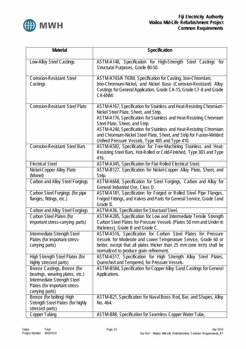
Fiji Electricity Authority Wailoa Mid-Life Refurbishment Project
Common Requirements
Status Final Page 23 Apr 2016 Project Number 80507610 Our Ref − Wailoa Mid-Life Refurbishment Common Requirements_R1
Material Specification
Low-Alloy Steel Castings ASTM-A148, Specification for High-Strength Steel Castings for Structural Purposes, Grade 80-50.
Corrosion-Resistant Steel Castings
ASTM-A743/A 743M, Specification for Casting, Iron-Chromium, Iron-Chromium-Nickel, and Nickel Base (Corrosion-Resistant) Alloy Castings for General Application, Grade CA-15, Grade CF-8 and Grade CA-6NM.
Corrosion-Resistant Steel Plate ASTM-A167, Specification for Stainless and Heat-Resisting Chromium-Nickel Steel Plate, Sheet, and Strip. ASTM-A176, Specification for Stainless and Heat-Resisting Chromium Steel Plate, Sheet, and Strip. ASTM-A240, Specification for Stainless and Heat-Resisting Chromium and Chromium-Nickel Steel Plate, Sheet, and Strip for Fusion-Welded Unfired Pressure Vessels, Type 405 and Type 410.
Corrosion-Resistant Steel Bars ASTM-A582, Specification for Free-Machining Stainless and Heat- Resisting Steel Bars, Hot-Rolled or Cold-Finished, Type 303 and Type 416.
Electrical Steel ASTM-A345, Specification for Flat Rolled Electrical Steel. Nickel-Copper Alloy Plate (Monel)
ASTM-B127, Specification for Nickel-Copper Alloy Plate, Sheet, and Strip.
Carbon and Alloy Steel Forgings ASTM-A668, Specification for Steel Forgings, Carbon and Alloy for General Industrial Use, Class D.
Carbon Steel Forgings (for pipe flanges, fittings, etc.)
ASTM-A181, Specification for Forged or Rolled Steel Pipe Flanges, Forged Fittings, and Valves and Parts for General Service, Grade I and Grade II.
Carbon and Alloy Steel Forgings ASTM-A36, Specification for Structural Steel. Carbon Steel Plates (for important stress-carrying parts)
ASTM-A285, Specification for Low and Intermediate Tensile Strength Carbon Steel Plates for Pressure Vessels (Plates 50 mm and Under in thickness), Grade B and Grade C.
Intermediate Strength Steel Plates (for important stress- carrying parts)
ASTM-A516, Specification for Carbon Steel Plates for Pressure Vessels for Moderate and Lower Temperature Service, Grade 60 or better, except that all plates thicker than 25 mm (one inch) shall be normalized to produce grain refinement.
High Strength Steel Plates (for highly stressed parts)
ASTM-A517, Specification for High Strength Alloy Steel Plates, Quenched and Tempered, for Pressure Vessels.
Bronze Castings, Bronze (for bearings, wearing plates, etc.) Intermediate Strength Steel Plates (for important stress- carrying parts)
ASTM-B584, Specification for Copper Alloy Sand Castings for General Applications.
Bronze (for bolting) High Strength Steel Plates (for highly stressed parts)
ASTM-B21, Specification for Naval Brass Rod, Bar, and Shapes, Alloy No. 464.
Copper Tubing ASTM-B88, Specification for Seamless Copper Water Tube,

Fiji Electricity Authority Wailoa Mid-Life Refurbishment Project
Common Requirements
Status Final Page 24 Apr 2016 Project Number 80507610 Our Ref − Wailoa Mid-Life Refurbishment Common Requirements_R1
Material Specification
Bronze Castings, Bronze (for bearings, wearing plates, etc.)
Type K.ASTM-B584, Specification for Copper Alloy Sand Castings for General Applications.
Copper Pipe ASTM-B42, Specification for Seamless Copper Pipe, Standard Sizes. Steel Pipe ASTM-A53, Specification for Welded and Seamless Steel Pipe. Stainless Steel Pipe ASTM A312, Type 316L Specification for Seamless and Welded
Austenitic Stainless Steel Pipe.. Stainless Steel Pipe Fittings ASTM A182, Type 316L Forged Stainless Steel Fittings, Socket-
Welding and Threaded. ASTM A403, Type 316L Specification for Wrought Austenitic Stainless Steel Pipe Fittings.
Stainless Steel Tubing ASTM A269 or ASTM A213, Grade TP316L Specification for Soft Annealed Stainless Steel Tubing.
Stainless Steel Tube Fittings Compression type stainless steel flareless tube fittings, suitable for 1200 psi working pressure. To SAE J514.
Steel Pipe Flanges and Flanged Fittings
ANSI-B16.5, Steel Pipe Flanges and Flanged Fittings.
2.4 Test of Materials
2.4.1 General
All materials or parts used in the equipment shall be new and shall be tested, in conformity with applicable methods prescribed by the ASTM, or such other equivalent authorized organizations.
2.4.2 Impact and Bend Tests
Materials for all principal parts shall be tested for impact resistance using the Charpy “V” notch specimen and shall have an impact resistance of not less than 2.1 kg·m at 10°C. Testing shall conform to the requirements of ASTM A370 and E23. Both longitudinal and transverse impact tests shall be performed for each heat on plate steel. Bend tests shall be performed on specimens of all major steel castings and forgings, in accordance with the applicable ASTM designation. The nil ductility transition temperature shall be the temperature at which the impact resistance is 2.1 kg·m as specified above. Where plate material used for the principal parts is of a type which experience has shown will consistently meet the impact-nil ductility requirements specified herein, impact testing of plates may be eliminated, subject to the Contractors submitting data demonstrating satisfactory evidence.
2.4.3 Test Certificates
Certified material test reports shall be submitted as soon as possible after the tests are made. The test certificates shall identify the component for which the material is to be used and shall contain all information necessary to verify compliance with these Employer’s Requirements.
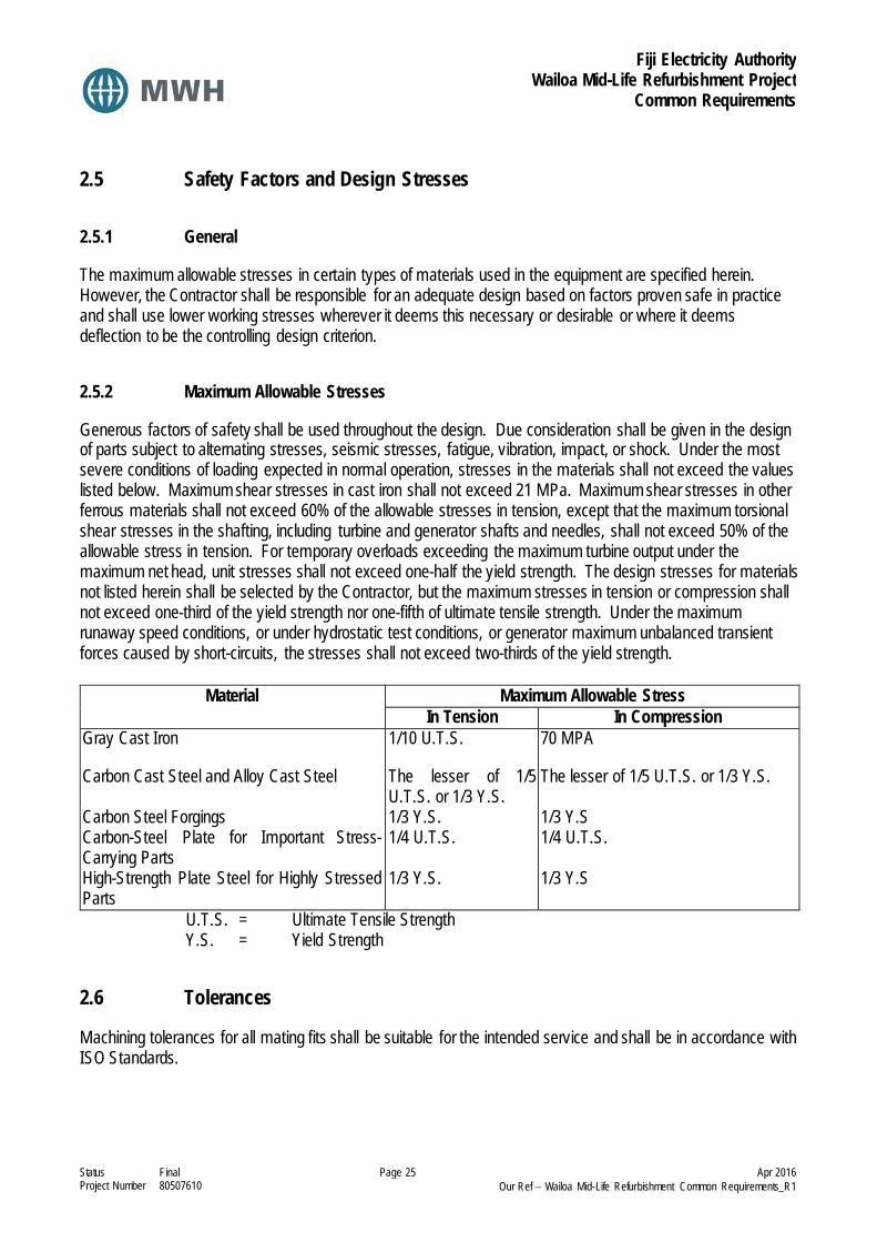
Fiji Electricity Authority Wailoa Mid-Life Refurbishment Project
Common Requirements
Status Final Page 25 Apr 2016 Project Number 80507610 Our Ref − Wailoa Mid-Life Refurbishment Common Requirements_R1
2.5 Safety Factors and Design Stresses
2.5.1 General
The maximum allowable stresses in certain types of materials used in the equipment are specified herein. However, the Contractor shall be responsible for an adequate design based on factors proven safe in practice and shall use lower working stresses wherever it deems this necessary or desirable or where it deems deflection to be the controlling design criterion.
2.5.2 Maximum Allowable Stresses
Generous factors of safety shall be used throughout the design. Due consideration shall be given in the design of parts subject to alternating stresses, seismic stresses, fatigue, vibration, impact, or shock. Under the most severe conditions of loading expected in normal operation, stresses in the materials shall not exceed the values listed below. Maximum shear stresses in cast iron shall not exceed 21 MPa. Maximum shear stresses in other ferrous materials shall not exceed 60% of the allowable stresses in tension, except that the maximum torsional shear stresses in the shafting, including turbine and generator shafts and needles, shall not exceed 50% of the allowable stress in tension. For temporary overloads exceeding the maximum turbine output under the maximum net head, unit stresses shall not exceed one-half the yield strength. The design stresses for materials not listed herein shall be selected by the Contractor, but the maximum stresses in tension or compression shall not exceed one-third of the yield strength nor one-fifth of ultimate tensile strength. Under the maximum runaway speed conditions, or under hydrostatic test conditions, or generator maximum unbalanced transient forces caused by short-circuits, the stresses shall not exceed two-thirds of the yield strength.
Material Maximum Allowable Stress In Tension In Compression
Gray Cast Iron 1/10 U.T.S. 70 MPA
Carbon Cast Steel and Alloy Cast Steel The lesser of 1/5 U.T.S. or 1/3 Y.S.
The lesser of 1/5 U.T.S. or 1/3 Y.S.
Carbon Steel Forgings 1/3 Y.S. 1/3 Y.S Carbon-Steel Plate for Important Stress-Carrying Parts
1/4 U.T.S. 1/4 U.T.S.
High-Strength Plate Steel for Highly Stressed Parts
1/3 Y.S. 1/3 Y.S
U.T.S. = Ultimate Tensile Strength Y.S. = Yield Strength
2.6 Tolerances
Machining tolerances for all mating fits shall be suitable for the intended service and shall be in accordance with ISO Standards.

Fiji Electricity Authority Wailoa Mid-Life Refurbishment Project
Common Requirements
Status Final Page 26 Apr 2016 Project Number 80507610 Our Ref − Wailoa Mid-Life Refurbishment Common Requirements_R1
2.7 Workmanship
All work shall be performed and completed in a thorough workmanlike manner and shall follow the best modern practices in the design and manufacture of the types of equipment specified herein. All Work shall be done by personnel skilled in the related professions and trades. All parts shall be made accurately to a standard gage, so as to facilitate replacement and repairs. All bolts, nuts, screws, rivets, threads, pipe, gauges, gears, and measurements or dimensions shown on the Drawings shall conform to customary standards. The Contractor shall provide and maintain in storage for at least 10 years, free of cost to the Employer, sufficient templates, gauges, patterns, and other records to enable the Contractor to make repair and replacement parts. All special gages and templates necessary for field erection shall be furnished and shall become the property of the Employer. Patterns will remain the property of the Contractor.
2.8 Welding
2.8.1 General
All welding shall be performed by the electric-arc method, by a process that excludes the atmosphere from the molten metal, and, where practicable, by automatic machines. After being deposited, all welds shall be cleaned of slag by shot blasting, unless otherwise approved, and shall be uniform, smooth, showing good fusion with the base metal, and free of voids, crack, and clinkers. Machined surfaces of parts affected by welding shall be machined to final dimensions after welding. Machined surfaces of parts requiring stress relief shall be machined to final dimensions after the parts have been stress relieved. Localized stress relieving will not be permitted for factory welded parts. All principal load carrying welds shall be full penetration type welds. Strength of welded joints shall be based upon the allowable stress of the parent materials specified in 2D.10, Safety Factors and Design Stresses.
2.8.2 Edge Preparation
Members to be joined by welding may be cut to shape and size by mechanical means such as shearing, machining, grinding, or by gas or arc cutting, to suit the conditions. Design of welded joints and selection of weld filler metal shall allow thorough penetration and good fusion of the weld with the base metal. The edges of surfaces to be welded shall be sound metal free of visible defects, such as laminations or defects caused by cutting operations, and free from rust, oil, grease and other foreign matter.
2.8.3 Welding Qualifications
The qualification of welding procedures, welders, and welding operators for all welding of pressure-containing components, including weld repairs and other high stressed components, shall conform to standards at least equal to Section IX of the ASME “Boiler and Pressure Vessel Code”. For welding of structural parts, the qualifications shall conform to standards at least equal to the AWS “Standard Qualification Procedure.” The Contractor shall furnish the facilities and all equipment, materials, and other articles required to perform qualification tests of its welders and welding operators. Certificates of welders' qualifications shall be furnished when requested. The procedure for qualification testing of the field welders shall be prepared by the Contractor, and the qualification tests shall be witnessed and accepted by the Contractor.
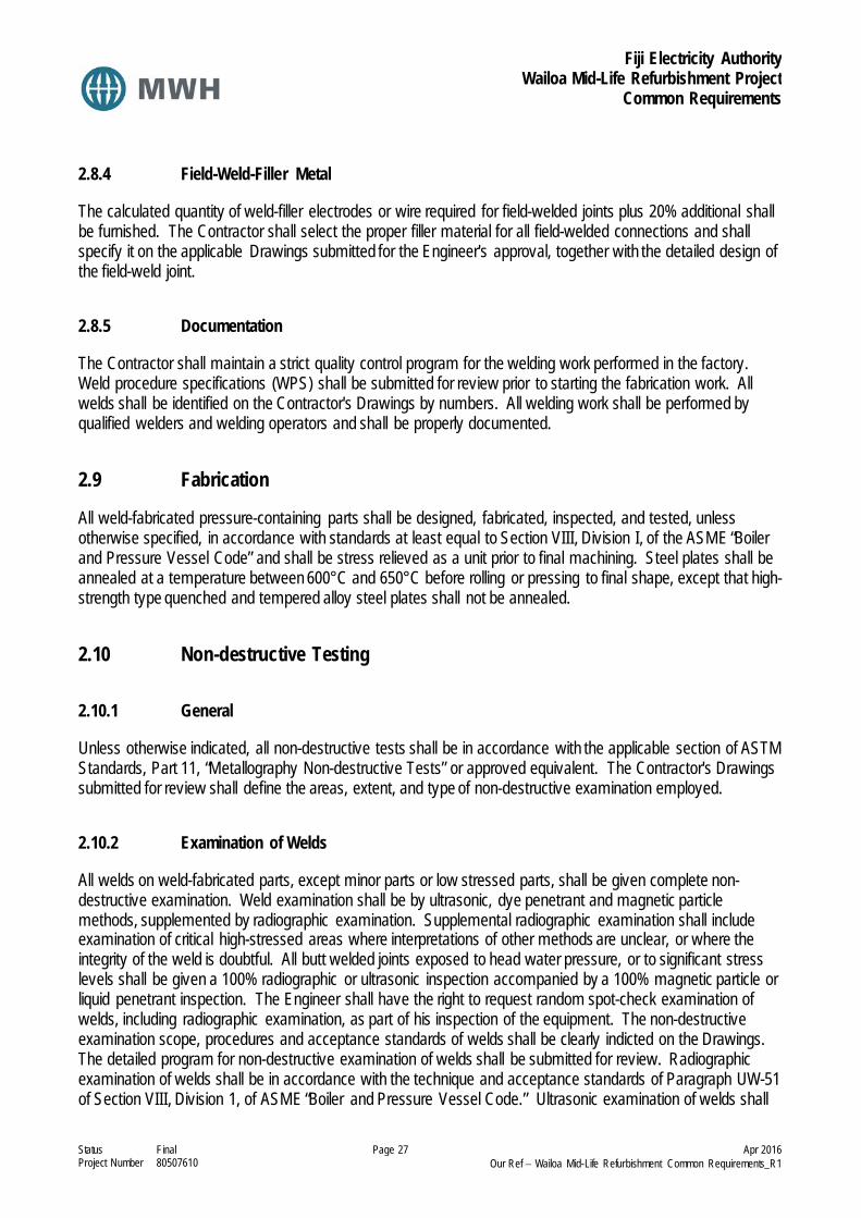
Fiji Electricity Authority Wailoa Mid-Life Refurbishment Project
Common Requirements
Status Final Page 27 Apr 2016 Project Number 80507610 Our Ref − Wailoa Mid-Life Refurbishment Common Requirements_R1
2.8.4 Field-Weld-Filler Metal
The calculated quantity of weld-filler electrodes or wire required for field-welded joints plus 20% additional shall be furnished. The Contractor shall select the proper filler material for all field-welded connections and shall specify it on the applicable Drawings submitted for the Engineer's approval, together with the detailed design of the field-weld joint.
2.8.5 Documentation
The Contractor shall maintain a strict quality control program for the welding work performed in the factory. Weld procedure specifications (WPS) shall be submitted for review prior to starting the fabrication work. All welds shall be identified on the Contractor's Drawings by numbers. All welding work shall be performed by qualified welders and welding operators and shall be properly documented.
2.9 Fabrication
All weld-fabricated pressure-containing parts shall be designed, fabricated, inspected, and tested, unless otherwise specified, in accordance with standards at least equal to Section VIII, Division I, of the ASME “Boiler and Pressure Vessel Code” and shall be stress relieved as a unit prior to final machining. Steel plates shall be annealed at a temperature between 600°C and 650°C before rolling or pressing to final shape, except that high-strength type quenched and tempered alloy steel plates shall not be annealed.
2.10 Non-destructive Testing
2.10.1 General
Unless otherwise indicated, all non-destructive tests shall be in accordance with the applicable section of ASTM Standards, Part 11, “Metallography Non-destructive Tests” or approved equivalent. The Contractor's Drawings submitted for review shall define the areas, extent, and type of non-destructive examination employed.
2.10.2 Examination of Welds
All welds on weld-fabricated parts, except minor parts or low stressed parts, shall be given complete non-destructive examination. Weld examination shall be by ultrasonic, dye penetrant and magnetic particle methods, supplemented by radiographic examination. Supplemental radiographic examination shall include examination of critical high-stressed areas where interpretations of other methods are unclear, or where the integrity of the weld is doubtful. All butt welded joints exposed to head water pressure, or to significant stress levels shall be given a 100% radiographic or ultrasonic inspection accompanied by a 100% magnetic particle or liquid penetrant inspection. The Engineer shall have the right to request random spot-check examination of welds, including radiographic examination, as part of his inspection of the equipment. The non-destructive examination scope, procedures and acceptance standards of welds shall be clearly indicted on the Drawings. The detailed program for non-destructive examination of welds shall be submitted for review. Radiographic examination of welds shall be in accordance with the technique and acceptance standards of Paragraph UW-51 of Section VIII, Division 1, of ASME “Boiler and Pressure Vessel Code.” Ultrasonic examination of welds shall

Fiji Electricity Authority Wailoa Mid-Life Refurbishment Project
Common Requirements
Status Final Page 28 Apr 2016 Project Number 80507610 Our Ref − Wailoa Mid-Life Refurbishment Common Requirements_R1
be in accordance with the methods and acceptance standards of the ASME Code, Section VIII, Division 1, Appendix 12. Magnetic particle examination of welds shall be in accordance with the methods and acceptance standards of the ASME Code, Section VIII, Division 1, Appendix 6. Liquid penetrant examination of welds shall be in accordance with the methods and acceptance standards of the ASME Code, Section VIII, Division 1, Appendix 8.
2.10.3 Examination of Castings
Major castings incorporated in the equipment or their components that are castings, shall be given complete non-destructive examination by ultrasonic, dye penetrant, and magnetic particle methods supplemented by radiographic examination. Supplemental radiographic examination shall include examination of critical high-stressed areas where interpretation of other methods is unclear or where the integrity of the casting is doubtful. Non-destructive examination of other castings shall be in accordance with accepted good practice to assure sound castings and shall be indicated on the Drawings. The non-destructive examination of steel castings shall be in accordance with the following methods and acceptance standards:
Examination Method Standard for Method Standard for Acceptance Radiographic ASME Sec. VIII, Div. 1, Appendix 7 ASME Sec. VIII, Div. 1, Appendix 7
Ultrasonic ASME Sec. V, Art. 5 ASME Sec. V, Art. 23, SA609 Magnetic Particle ASME Sec. VIII, Div. 1, Appendix 7 ASME Sec. VIII, Div. 1, Appendix 7
Liquid Penetrant ASME Sec. VIII, Div. 1, Appendix 7 ASME Sec. VIII, Div. 1, Appendix 7
2.10.4 Examination of Forgings
Forgings for the shafts, needles (if made of forgings), and shaft coupling bolts shall be given complete ultrasonic examination with liberal overlap and other approved non-destructive tests, to determine that they are sound. Non-destructive examination of other forgings shall be in accordance with accepted good practice to assure their soundness and shall be indicated on the Drawings. The structure of forgings shall be homogeneous and free from excessive non-metallic inclusions. An excessive concentration of impurities or separation of alloying elements at critical points in a forging will be cause for its rejection. Examination of steel forgings shall be in accordance with the methods and acceptance standards of ASTM A388, “Standard Practice for Ultrasonic Examination of Heavy Steel Forgings,” and of ASTM A275, “Standard Method for Magnetic Particle Examination of Steel Forgings.”
2.11 Steel Castings
2.11.1 General
Castings shall be free from injurious defects and shall be satisfactorily cleaned for their intended use. Surfaces of castings which do not undergo machining and which are exposed to view in the installation shall be dressed for good appearance and for painting. The locations of existing defects shall be determined, and all defects,

Fiji Electricity Authority Wailoa Mid-Life Refurbishment Project
Common Requirements
Status Final Page 29 Apr 2016 Project Number 80507610 Our Ref − Wailoa Mid-Life Refurbishment Common Requirements_R1
which impair the strength or utility of the casting, shall be removed to sound metal. The structure of the castings shall be homogeneous and free from excessive non-metallic inclusions. An excessive concentration of impurities or separation of alloying elements at critical points in a casting will be cause for its rejection. Bend tests shall be performed on all major castings as specified under 2D.9, Test of Materials.
2.11.2 Inspection
Castings shall be inspected visually at the foundry after they are cleaned, while test pieces are removed, and while defects are being removed. Castings shall also be inspected after repairs and after heat treatment. Radiographic or other non-destructive tests will be required as specified under 2D.15, Non-destructive Testing, and as otherwise approved by the Engineer when granting permission to repair major defects. The Engineer reserves the right to require non-destructive tests at the Contractor's expense to determine a) the full extent of defects, b) that the area is properly prepared for welding, and c) that the repairs are satisfactory.
2.11.3 Repair Welding
Before proceeding with repairs the Contractor shall submit a descriptive report on the casting defects, including Drawings showing the location and size of major and minor defects, supplemented with photos, sketches and metallurgical test reports, results of non-destructive examinations, dimensional stability, metal wall thickness, shrinkage, perforations, etc. The report shall define the type of defect, probable causes and the changes recommended in the design of the component or in the casting technique to prevent similar defects in consecutive castings. Similarly, the detailed repair procedure shall be submitted, including the non-destructive tests to be applied and the finished repair. Minor defects or imperfections that will not impair the strength or serviceability of the castings may be repaired by welding in accordance with accepted foundry practice without approval but in any case shall be reported to the Engineer. Defects shall be considered minor when the cavity properly prepared for welding is not greater than 25% of the actual wall thickness but in no case greater than 25 mm and when the area to be welded is not greater than 160 cm2. An accumulation or concentration of minor defects shall be considered as a major defect. The accumulation of major defects and/or concentration of minor defects which in the opinion of the Engineer casts doubt as to the quality of the casting may be cause for its rejection. If removal of the defects reduces the stress-resisting cross section of the casting by more than 30% or if the calculated stress in the remaining metal exceeds the allowable stress by more than 30%, the casting shall be rejected. All castings having major defects repaired or accumulation of minor defects after heat treatment, or any defects which will impair the strength of the stress-resisting cross section or the dimensional stability of the finished part repaired after heat treatment, shall be reheat treated.
2.11.4 Dimensions
Dimensions of castings shall not be reduced by factory or foundry practices by an amount sufficient either to impair by more than 10% the strength of castings (calculated from Drawing dimensions) or to cause the stresses to exceed those allowed under these Employer’s Requirements. Dimensions shall not be oversized to the extent that the castings interfere with processing operations or proper fit with other parts. Warped or otherwise distorted castings shall not be used in the Work without presenting complete details for review.

Fiji Electricity Authority Wailoa Mid-Life Refurbishment Project
Common Requirements
Status Final Page 30 Apr 2016 Project Number 80507610 Our Ref − Wailoa Mid-Life Refurbishment Common Requirements_R1
2.12 Surface Finish of Equipment Parts and Welds
2.12.1 Weld Finish
Welds shall in general be treated so that they will display good appearance and a surface suitable for painting. Structural welds shall be ground and blended, to avoid stress raisers. All welds which require radiographic or other non-destructive examination shall be dressed by chipping and grinding as required for good interpretation of radiographic film or interpretation by other weld examination methods. Welds exposed in water passages shall be ground to provide smooth-contoured hydraulic surfaces. The welded joints of the air receivers and oil pressure tanks shall not be ground to the extent that the tank is weakened structurally. Details of weld dressing and finishing and non-destructive testing (NDT) shall be shown on the Drawings submitted for approval.
2.12.2 Hydraulic Packing
Packing for seals shall be a high-grade commercial product and where feasible, with polytetrafluorethylene (PTFE) content suitable for the application and for long seal life. Packing grooves, which are exposed to river water, shall be protected from corrosion, by the use of corrosion-resistant materials.
2.12.3 Auxiliary Equipment and Data
Items of equipment such as pumps, motors, valves, and similar small pieces of equipment and accessories shall be, to the greatest extent practicable, of a type that is readily available or can be readily imported. The names of manufacturers of mechanical and electrical auxiliary equipment to be incorporated in the work, together with performance characteristics and other significant information, shall be submitted to the Engineer for review. Equipment incorporated in the work without prior review and approval shall be subject to rejection.
2.12.4 Nameplates
Each major and auxiliary item of equipment shall have a nameplate permanently affixed thereto showing in a legible and durable manner the serial number, name and address of the manufacturer, ratings, characteristics, weight, manufacturing date and other significant information, as applicable. Nameplates of distributing agents only shall not be acceptable. Additional nameplates shall be provided to indicate main operating instructions, caution or warning for personnel and operational safety. In addition, each panel-mounted instrument, position indicator, pushbutton, switch, light, or other similar device shall be identified by a permanently affixed nameplate describing the control functions. Electrical wiring and instruments including relays shall also be labelled to correspond to the numbers assigned on the electrical control schematics. The above general nameplate requirements shall be used in preparing nameplate lists and Drawings to be submitted to the Engineer for review. Drawings for nameplates, as they will appear on the finished equipment, shall be submitted for review.

Fiji Electricity Authority Wailoa Mid-Life Refurbishment Project
Common Requirements
Status Final Page 31 Apr 2016 Project Number 80507610 Our Ref − Wailoa Mid-Life Refurbishment Common Requirements_R1
All nameplates shall be in English and shall be suitably engraved and shall be weather-resistant. All nameplates shall be permanently attached to the respective parts, components, or equipment items in clearly visible locations. Nameplates for control equipment shall be screw mounted laminated plastic, white with black cores, with engraved capital letters 6 mm minimum height.
2.13 Piping
2.13.1 General
Piping, pipe materials, pipe supports, and hangers shall be in accordance with standards at least equal to ANSI B31.1.0, “Power Piping.” The arrangement of piping and locations of valves and joints shall be such that there will be minimum disturbance of the piping and interference with other equipment and systems when the turbine, generator, or other equipment is dismantled or parts are removed for inspection or repairs. Bolted flange connections or unions shall be provided at points where a piping system must be disconnected for dismantling.
2.13.2 Water Piping
Water piping shall be of welded grade 316L stainless steel pipe. Piping connection shall be of welded joints for embedded water piping and welded joints and flanged fittings for exposed water piping. Valves 75 mm and smaller shall be of stainless steel; valves 100 mm and larger shall be cast steel flanged valves with stainless steel trim, epoxy-coated inside. Sanitary water pipe downstream of the storage tank may be copper or polybutylene. Insulation Insulate all hot surfaces, pipe, valves, fittings to ensure surface temperature is low enough to be safe to touch and to prevent excessive heat loss. Insulate all cold surfaces to prevent condensation being formed on the surface and to prevent excessive heat gain. Insulation on cold surfaces shall be vapour sealed type to prevent migration of vapour from the warm side into the insulation. No insulation is to be applied to pipework until they have been proven to be water, air and gas tight as applicable. All thermal insulation and cladding systems shall be in accordance with the requirements of BS 5970 - Code of Practice for the Thermal Insulation of Pipework and Equipment. Thermal insulation shall be in-situ foamed polyurethane type with aluminium cladding. Foam glass ferrules shall be used at pipe support locations. Water lines shall be insulated and clad such that no condensation forms on the surfaces of the pipe, cladding or pipe supports under normally expected operating conditions and temperatures. All pipework and equipment insulation is to be neatly trimmed around valve bonnets, drain cocks, vents, etc. to enable normal operation and maintenance without the need to remove the insulating material.

Fiji Electricity Authority Wailoa Mid-Life Refurbishment Project
Common Requirements
Status Final Page 32 Apr 2016 Project Number 80507610 Our Ref − Wailoa Mid-Life Refurbishment Common Requirements_R1
2.13.3 Oil Piping
Pressure piping for jacks and servomotors shall be grade 316L stainless steel, of appropriate strength, with steel fittings and steel bodied valves. Valves shall have bronze seats and stems. Lubricating oil piping shall be seamless drawn copper or red brass with brass or bronze fittings and valves.
2.13.4 Piping Integral with Turbine Water Passages
Piping for the distributor drains turbine pit drain, and any other lines connected to the penstock, turbine, or distributor shall be welded steel pipe, epoxy-coated inside, with flanged fittings. Valves 75 mm and smaller shall be of grade 316L stainless steel; valves 100 mm and larger shall be cast steel, flanged, wedge disc gate valves with stainless steel trim, epoxy-coated inside.
2.13.5 Piezometer and Pressure Tap Piping
Piezometer and pressure tap piping on the turbine shall be 20 mm grade 316L stainless steel tubing and fittings, as specified in 2D.8, Materials. All piezometer taps shall be individually piped to valve panels provided at suitable locations. Each piezometer line shall be valved and labelled at the valve panel. Provisions for blowing out the lines with compressed air, for venting air from the lines and for connection to pressure measuring devices shall be included.
2.13.6 Compressed Air Piping
Compressed air piping for pressures up to 9 bar shall be ASTM-A53 Schedule 40 black steel pipe, welded grade, with screwed fittings for sizes up to 60 mm and with butt weld fittings for larger sizes. ASTM-A53 Schedule 80 black steel, seamless pipe shall be used for higher pressures with screwed or socket-weld forged steel fittings.
2.13.7 Instrument Piping
Piping exposed to river water shall be grade 316L stainless steel tubing with stainless steel compression type fittings and shut-off valves. All other piping shall be brass or copper with brass or bronze screwed fittings or of copper tubing. Shut-off valves shall be provided at pressure gauges and at points where the gauge piping connects to the main equipment, together with suitable blow-off valves and drain connections. Flexible tubing for the dial thermometers shall be armoured.
2.13.8 Governor and Inlet Valve Oil Pressure Piping
The governor and inlet valve shall be provided with interconnecting piping and valves between the various parts of the oil pressure systems and their respective operating servomotors. The piping shall be sized for a maximum oil velocity of 5.0 m/s for servomotor travel at the maximum rate. The main pressure oil piping shall be grade 316L stainless steel pipe with welded joints and bolted steel flanges, or threaded connections for any connections required to permit assembly and disassembly of the piping system. Threaded pipe connections shall use stainless steel connections complying with SAE J514. All piping shall be thoroughly cleaned by

Fiji Electricity Authority Wailoa Mid-Life Refurbishment Project
Common Requirements
Status Final Page 33 Apr 2016 Project Number 80507610 Our Ref − Wailoa Mid-Life Refurbishment Common Requirements_R1
pickling in the factory (removing all mill scale, loose or tight), oiled inside, painted on the outside and protected for shipment by wooden protectors on all flanges and protective closures on pipe ends. All valves, except valves built-in and forming an integral part of the governor pumping unit, shall be of the rising-stem, steel body type. Gate valves in the pressure lines shall be cast-steel, solid-wedge type, with close guide clearances to minimize vibration of the gates when operating at partial opening. Where feasible, long-radius pipe bends shall be used in place of pipe fittings. Piping shall be factory fabricated to the maximum extent possible, consistent with erecting, handling, and shipping requirements.
2.13.9 Carbon Dioxide Piping
Carbon dioxide system piping up to and including 20 mm shall be standard weight galvanized steel; carbon dioxide piping larger than 20 mm shall be extra heavy galvanized steel.
2.13.10 Pipe Supports and Piping Materials
Adequate pipe supports shall be provided for all piping included in the supply. Supports, pipe hangers, wall brackets, pipe clamps, fastening devices and all necessary studs, bolts, nuts, washers, oil-resistant gaskets, packing, etc., required for the piping systems shall be furnished. These items shall be supplied as finished products requiring no field fabrication such as welding, cutting and drilling.
2.13.11 Piping Connections
On connections for all equipment, pipes may be threaded or flanged with the flanges faced and drilled in accordance with standards selected by the Contractor. All flanged external connections shall be provided with bolts, nuts and gaskets for connection to piping furnished by others. All governor and inlet valve oil piping, generator oil lubricating piping, high pressure oil lift piping, generator brakes and jack piping, generator oil mist piping, generator CO2 piping, generator brake dust collection piping, etc. shall be furnished as a part of a complete system.
2.14 Pumps
2.14.1.1 General Pumps shall be installed strictly according to the pump manufacturer's requirements. Every effort shall be made to ensure that the minimum number of pump vendors are used as suppliers, and that pumps with identical duties are interchangeable in every respect. The pump and motor combination shall be selected so that non-overloading operation is ensured under all flow conditions.

Fiji Electricity Authority Wailoa Mid-Life Refurbishment Project
Common Requirements
Status Final Page 34 Apr 2016 Project Number 80507610 Our Ref − Wailoa Mid-Life Refurbishment Common Requirements_R1
2.14.1.2 General Requirements for Pumps Pumps shall be of a design and capacity capable of maintaining the fluid flow rate at the actual system resistance. The material and construction of the pump shall be suitable for the type, temperature and pressure of the fluid to be handled. All moving parts of the pump shall be statically and dynamically balanced. All pumps shall either be fitted with mechanical seals or be of canned construction so there is no liquid path past a moving surface. Mechanical seals shall be used wherever possible. The preferred sealing face combination is carbon on silicon carbide. Seals shall be water flushed wherever practicable.
2.14.1.3 Centrifugal Type Pumps for General Use Pump installations shall consist of pump casing, impeller, suction and discharge connections, driven shaft, couplings and motor as stated. Pumps shall be complete with all necessary water seals. Pump installations shall comprise suction and discharge pipe reducers and expansion pieces directly connected to the pump connections, vibration isolation equipment, and motor terminal box suitable for connection to a flexible conduit system. Generally, pump base plates shall be constructed from cast iron, however unit constructed close coupled pumps may be mounted on mild steel rails or a fabricated mild steel flat bed plate if full corrosion resistant surface treatment is provided. Pump flanges shall be tapped and plugged to receive gauge connections. Volute casings shall be drilled, tapped and plugged at the bottom to enable complete drainage to be carried out. Spherical roller bearings, or in light load applications deep groove ball bearings, are required on all pumps using rolling element bearings and shall be arranged to operate either within an oil reservoir or with grease lubrication. Parallel roller bearings are not permitted. Bearing lubricators shall be fitted with drain plugs and oil content indication. Impellers and couplings shall be keyed to the drive shaft, the impeller being retained by a hexagonal nut. Shafts shall be fitted with water deflectors. Unless specifically indicated elsewhere in this document, motor enclosures shall be totally enclosed fan cooled. Belt driven pumps shall not be permitted, except in the case of gear pumps. Unit-constructed close coupled pumps shall be of the back pull-out type, enabling the motor, drive and impeller to be withdrawn from service without disturbing the volute casing connections, piping, etc. Where pumps are to be coupled to their prime mover on site, the motor and pump shall be carefully levelled on shims and packing to achieve a close order of alignment. Dial gauges shall be used to achieve this end and the maximum permitted eccentricity shall be 0.05 mm.

Fiji Electricity Authority Wailoa Mid-Life Refurbishment Project
Common Requirements
Status Final Page 35 Apr 2016 Project Number 80507610 Our Ref − Wailoa Mid-Life Refurbishment Common Requirements_R1
Care shall be taken that the connecting pipe is so arranged as to ensure that no stresses are transmitted through the connections to the pump casing.
2.14.1.4 Performance The Contractor shall provide pump characteristics, power and efficiency curves certified by an internationally recognised authority to the Engineer for approval. All pumps shall operate with no cavitation. In the case of pumps operating at elevated temperatures, the Contractor shall demonstrate to the Engineers satisfaction, the no cavitation will occur under all normal operation conditions. Detailed NPSH calculations shall be submitted for approval by the Engineer.
2.15 Foundation Materials
2.15.1 General
All permanent foundation materials including all anchor bolts, jacks, tie rods, turnbuckles, anchor loops, levelling screws, supporting columns made of pipe or structural steel, soleplates, embedded anchor plates, bracing, and all other foundation materials required for anchoring and/or supporting the parts during concreting, shall be furnished with the equipment.
2.15.2 Design
Tie-down rods and bracing for the distributor shall be designed to firmly hold it in place while it being embedded. Tie rods for the wheel pit liner and pit liner shall be similarly designed. The necessary bars required to transfer the uplift or downpull on the turbine components into the surrounding concrete shall be designed and furnished. All jacks shall have steel bases and steel caps so that they can be welded to the parts which they support and to the jack supports.
2.15.3 Anchor Bolts
All anchor bolts and anchoring materials, including pipe sleeves, nuts, and plate washers required for anchoring the equipment and accessories, shall be furnished. Calculations showing the stresses in the anchor bolts for the needle servomotors and their operating cylinders shall be submitted for review.
2.16 Handling Devices
The rotor lifting device for attaching to the powerhouse crane shall be provided. Lifting brackets for attaching to the top of the turbine shaft, and the generator shaft shall also be provided. In addition, upending shoes required to upend the shafts from the horizontal to the vertical position shall be furnished. The Contractor shall coordinate the rotor and shaft handling details with the Engineer.

Fiji Electricity Authority Wailoa Mid-Life Refurbishment Project
Common Requirements
Status Final Page 36 Apr 2016 Project Number 80507610 Our Ref − Wailoa Mid-Life Refurbishment Common Requirements_R1
Lifting lugs, brackets, eyes etc., as required for attaching lifting devices shall be provided on all of the major components of the equipment. All slings and lifting devices required for attachment to the components and assemblies and to the powerhouse crane-hook for handling during erection and disassembly shall be furnished.
2.17 Protection, Cleaning and Painting
2.17.1 General
All ferrous parts shall be protected, cleaned and painted in accordance with AS/NZS2312 “Guide to the protection of structural steel against corrosion by the use of protective coatings”. Where the requirements of this Standard differ from the requirements of the specification, the more onerous requirement shall apply. All parts which will ultimately be embedded in concrete shall be cleaned and protected by a cement wash or other approved method before forwarding from the Contractor's factory. Before being installed, they shall be thoroughly de-scaled and cleaned of all rust and adherent matter. Such cleaning must not affect the strength or final operation or function of the plant. All machined parts or bearing surfaces shall be cleaned and protected from corrosion by the application of an approved rust preventive lacquer or a peelable plastic film before forwarding from the Contractor's factory. Where the latter is impractical, such parts shall be heavily covered with high melting point grease. After erection, such parts shall be cleaned with solvent and wiped or polished bright. All parts, other than machined parts that will be exposed after erection, shall be thoroughly cleaned and given two coats of best quality approved primer and one coat of best quality approved finish paint before being forwarded from the Contractor's factory. One further coat of paint of an approved quality and colour shall be applied after erection and touching up on the Site (except such apparatus as panels and instruments which shall be finish painted in the factory). Paint colours shall be submitted to the Engineer for approval by presentation of RAL ‘Classic’ or equivalent colour samples or colour chips Primer shall be applied to surfaces prepared in accordance with the paint Contractor's instructions. The surface shall be wiped clean immediately prior to applying the paint. The primer and finish coats of paint shall be applied using the methods and plant recommended by the manufacturer. The internal surface of all pipelines shall be cleaned out by approved methods before installation and again prior to commissioning, to ensure freedom from dirt, rust, scale, welding slag, etc. All exposed pipes shall be coloured for identification after erection is completed. The colour for each classified pipeline shall be approved by the Engineer. The final colour of all plant shall be approved by the Engineer. The Contractor shall comply with this colour scheme for the plant. All plant shall be painted as specified herein. The painting of plant shall include the preparation of the metal surfaces, paint application, protection and drying of the paint coatings, as well as the supplying of all tools, labour and materials necessary for the entire painting work.

Fiji Electricity Authority Wailoa Mid-Life Refurbishment Project
Common Requirements
Status Final Page 37 Apr 2016 Project Number 80507610 Our Ref − Wailoa Mid-Life Refurbishment Common Requirements_R1
Paint shall be the product of reputable manufacturers and its selection shall be approved by the Engineer. Sufficient paint shall be provided for site painting.
2.17.2 Employers Colour Scheme
The Employers Colour Scheme for the Wailoa powerhouse and appurtenant facilities is as follows:- Item Colour RAL Powerhouse Building Cladding Mist Green/Pale Eucalypt Steel Frame Caulfield Green/Cottage Green Handrails Signal Yellow RAL1003 Stairway Bearers Signal Yellow RAL1003 Ladders Signal Yellow RAL1003 Doors and frames Karaka Green Roller Door Mist Green/Pale Eucalypt Powerhouse & Laydown floor Signal Grey RAL7004 Powerhouse & Laydown floor "walkway markings" Signal Yellow RAL1003 Control Building Interior Walls Papyrus White RAL9018 Control Building Interior Ceilings Cream RAL9001 Control Panels Grey RAL 7032 11kV Switchgear Grey RAL 7032 Distribution Boards Grey RAL 7032 Turbine Light Blue RAL5012 Generator Mellon Yellow RAL1028 HPU Patina Green RAL6000 Main Inlet valve Patina Green RAL6000 Dewatering Valve Patina Green RAL6000 Lube Oil Patina Green RAL6000 Penstock Stub Section Patina Green RAL6000 Fire Pipework Signal Red RAL3001 Transformers Green Grey RAL7009 Crane and rails Signal Yellow RAL1003 Flood Pump Piping Patina Green RAL6000 Switchyard Building Cladding Mist Green/Pale Eucalypt Doors and frames Karaka Green Roller Door Mist Green/Pale Eucalypt Floor Signal Grey RAL7004 Interior Walls Papyrus White RAL9018

Fiji Electricity Authority Wailoa Mid-Life Refurbishment Project
Common Requirements
Status Final Page 38 Apr 2016 Project Number 80507610 Our Ref − Wailoa Mid-Life Refurbishment Common Requirements_R1
Interior Ceilings Cream RAL9001 Control Panels Grey RAL 7032 Transformers Green Grey RAL7009
2.17.3 Surface Preparation
All oil, paraffin, grease and dirt shall be removed from the surfaces to be painted using solvents. All weld spatters, slags, burrs, loose rusted mill scale and other foreign substances shall be removed by shot or sandblasting to "white" metal. The interior surface of the steel pipe shall be mechanically cleaned or sandblasted to a commercial standard. Special attention shall be given to cleaning of corners and converging angles. If rust forms or the surfaces become contaminated in the interval between cleaning and painting, re-cleaning to the same degree appropriate is required. Effective means shall be provided for removing all free oil and moisture from the air supply lines of blasting plant. All surface preparations shall be subject to the approval of the Engineer before any paint is applied.
2.17.4 Application Procedure
All paint, when applied, shall provide a satisfactory film and a smooth, even surface. Paint shall be thoroughly stirred, stained, and kept at the uniform consistency during application. Paint shall not be applied when the temperature of the metal or of the surrounding air is below 10°C. Surfaces that will be coated shall be performed by brushing or spraying. Each coat shall be allowed to dry or harden thoroughly before the succeeding coat is applied.
2.17.5 Surfaces Not to be Painted
Bronze, brass, surfaces of gear teeth, finished ferrous surfaces, surfaces in rolling or sliding contact after field assembly and wire ropes shall not be painted. All corrosion resisting steel surfaces for bearings and machinery parts shall not be painted. On completion of cleaning, such surfaces shall be coated with an adhesive plastic film to protect the surfaces from minor mechanical damage and corrosion during shipment and storage at the site. The film shall be stripped off immediately prior to field erection of the plant.
2.17.6 Galvanising
Unless specifically mentioned to the contrary, iron and steel shall be effectively galvanised after all fabrication is completed. The zinc coating shall be uniform, clean, smooth and as free from spangle as possible. Galvanising shall be applied by the hot dip process for all parts other than steel wires. All steel wires shall be galvanised by an approved method before stranding.

Fiji Electricity Authority Wailoa Mid-Life Refurbishment Project
Common Requirements
Status Final Page 39 Apr 2016 Project Number 80507610 Our Ref − Wailoa Mid-Life Refurbishment Common Requirements_R1
The minimum quantities of zinc coating shall be 350 g/m² for bolts and nuts and 550 g/m² for all other parts except steel wires. The uniformity of zinc coating, tested by dipping the sample into the solution of sulphate of copper, shall be such that no surface of iron or steel shall expose until four times of dipping for bolts and nuts and six times for all other parts. The preparation for galvanising and the galvanising itself shall not distort or adversely affect the mechanical properties of the materials. After galvanising, holes shall be free from nodules of splatter. Galvanised parts are subject to the formation of white rust during shipment or storage on the Site, and special treatment shall be made during the galvanising process to prevent the formation of white rust.
2.17.7 Paint Schedule
The painting shall be performed as follows:- Epoxy resin paint, total thickness of 0.15 - 0.25 mm shall be applied to the following items:- • Interior & external surfaces of steel conduits and valves • Interior & exterior surfaces of turbine housings All unfinished surfaces of ferrous metal except those specified in the above shall be given phthalic acid resin paint of alkyl resin enamel or other approved paints. Total thickness of these paints including primer coat shall be 0.12 - 0.15 mm. Commercial plant shall be painted in accordance with the manufacturer's standard practice. All finished surfaces of ferrous metals including screw threads that will be exposed during transportation or while awaiting installation shall be cleaned and given a heavy uniform coating of gasoline soluble, rust preventive compound.
2.18 Lubricants and Hydraulic Fluid
Oil for the hydraulic power units, for the governing systems, inlet valves, and the thrust and guide bearings shall be of the same type. Grease, lubricating oil and hydraulic fluid required for initial filling of all of the equipment plus 10% shall be furnished. Upon completion of the design, a tabulation confirming the quantities of lubricating oil, grease, and hydraulic fluid required for initial application for each item of equipment shall be furnished. Final selection of the grease, lubricating oil, and hydraulic fluid shall be coordinated with the Engineer to rationalize the oil inventory and to ensure that the selected brands are available locally.

Fiji Electricity Authority Wailoa Mid-Life Refurbishment Project
Common Requirements
Status Final Page 40 Apr 2016 Project Number 80507610 Our Ref − Wailoa Mid-Life Refurbishment Common Requirements_R1
2.19 Ventilation and Air Conditioning Systems
2.19.1 Ductwork
2.19.1.1 General Fabricate all ductwork in accordance with the appropriate Duct Manual produced by the Sheet Metal and Air Conditioning Contractor’s National Association (SMACNA). Install all ductwork in accordance with the recommendation of SMACNA and the American Society of Heating, Refrigerating and Air Conditioning Engineers (ASHRAE). Unless otherwise specified, ductwork shall be designed for a minimum operating static pressure of 500 Pa.
2.19.1.2 Duct Materials Rigid Rectangular Duct - unless otherwise specified, duct material shall be galvanised sheet steel for indoor ductwork. Duct material shall be aluminium, or where specifically called for, stainless steel, for ductwork outside the building exposed to weather, or sheltered but not enclosed. Flexible Connections - flexible connections shall be barium or lead loaded fabric, suitably rated for the specific application to limit noise breakout. Flexible connection shall be secured as follows:-
• On circular ducts : “Jubilee” type fasteners. • On rectangular ducts : Secure with approved “Soft” sealing compound and
metal strip, fastened at not less than 80mm centres by self taping screws.
Flexible Ductwork - Ensure that the radii of bends in these ducts does not exceed the manufacturer’s recommendations. Flexible ductwork shall only be used for a maximum total length of 3 m of in any branch.
2.19.1.3 Duct Construction & Installation Ducts shall be constructed to the requirement of SMACNA. Pressure rating of ductwork shall exceed maximum operating pressure of the duct work system. All rectangular ductwork shall be suitably stiffened in accordance with SMACNA recommendation. Flat panels of ducts shall be cross-broken. Unless otherwise stated, ductwork shall be constructed with galvanised sheet steel. Duct supports shall be at centres needed for rigidity and absence of noise, but in no case more than 2.5 m apart for ducts up to 600 mm wide, and 3 m apart for ducts over 600 mm size. Duct supports shall be of galvanised steel construction.

Fiji Electricity Authority Wailoa Mid-Life Refurbishment Project
Common Requirements
Status Final Page 41 Apr 2016 Project Number 80507610 Our Ref − Wailoa Mid-Life Refurbishment Common Requirements_R1
Suitable spacer shall be provided at support insulated duct to maintain insulation thickness and integrity of vapour seal. Duct supports shall incorporate vibration isolation pads. Comply with the details shown on the drawings for bends, branches etc. where detail is insufficient and in other cases, bends and branches shall be made of “easy sweep” wherever possible to a curve-ratio of not less than 0.5. Contractor shall thoroughly clean the supply ducting by rubbing down internally, and vacuuming cleaning out all dust, debris and other foreign materials immediately before balancing and commissioning of the system. Arrangements for installation of ductwork shall be made in good time before ceiling lining etc. are fixed, and all dimensions, length etc., shall be checked against actual site conditions before fabrication. Ductwork installed outside the building shall be sealed to water tight. Insulated ductwork outside the building shall be internally insulated.
2.19.1.4 Ductwork Accessories General Unless specified elsewhere in this specification to the otherwise, the following ductwork accessories shall be provided by the Contractor at locations as specified in the following, irrespective of whether such accessories have been shown on the drawing or not. a. Fire Dampers - provide fire dampers or fire collars at all duct penetrations through fire rated partitions, floors,
and ceilings. Fire dampers shall be of the same or higher than the fire rating as the compartmentation on which damper is installed.
b. Regulating Dampers - provide regulating dampers at the following locations:-
i Branch duct take-off from main distribution duct or distribution plenum. ii Exhaust outlet, fresh air intake and return air connection of each air handling system iii Air supply and exhaust grille iv Duct branch serving one grille; in this case, the grille damper should be omitted v At all direct driven fan discharge or suction ductwork
c. Test Openings - provide test openings at the following locations: i Upstream or downstream of regulating dampers. Where possible flow measurement opening shall be
located at the shorter side of the straight ductwork and shall be at a distance of not less than five times the shorter dimension of the duct downstream of the damper and any fitting to ensure that the air velocity profile is uniform across the duct section.
In the absence of such a location in the duct system due of physical constraint, a flow laminator shall be provided upstream of the flow measurement opening.
ii At all fan discharge or suction ductwork iii Upstream or downstream of all coils.

Fiji Electricity Authority Wailoa Mid-Life Refurbishment Project
Common Requirements
Status Final Page 42 Apr 2016 Project Number 80507610 Our Ref − Wailoa Mid-Life Refurbishment Common Requirements_R1
Provide test openings at no more than 300 mm intervals across the shortest dimension of the duct. Locate opening(s) as close to the mid section of the duct as possible.
d. Access Openings - provide access opening through duct wall at the following locations.
i. Adjacent to all fire dampers so that:-
• Fusible link can be checked or replaced • The operation of the fire damper can be tested periodically • Damper can be reopened after closing
ii Adjacent to all duct mounted coils, regulating damper and filter, at no more than 3 metre intervals along
the length of duct or between duct obstructions or fittings, for cleaning purposes.
Access openings shall be located at accessible side of the ductwork. Mountings of access doors shall be suitable for externally insulated duct work. Access doors shall be big enough for proper access.
e. Turning Vane and Splitter Damper - provide short chord turning vanes at all square elbows.
Provide splitter damper at all right angles branches from duct to grille. Provide long chord air turns at round elbow when the turning radius is less than 1½ times the width of the elbow.
All turning vanes at high velocity greater than 10 m/s shall be of aerofoil design.
f. Backdraught dampers - provide backdraught dampers at all duct entry into common exhaust plenum. Air
velocity over the backdraught damper shall not be higher than 3 m/s. g. Air tight dampers - air tight dampers shall be multi-blade type with interlocking trim fitted with silicon gasket. h. Fire Dampers - fire dampers shall be constructed with galvanised sheet steel of certified fire resistance period
of not less than two hours, and certified air leakage rate not more than 2% of the designed air flow rate when subject to air pressure of not less than 1.24 kPa.
Curtain type fire dampers shall be gravity closed when closed vertically and shall be spring closed when closed horizontally. Blade type fire damper shall be gravity closed. Damper shall be held in open position by fusible link set for 71°C to 79°C. Fusible link shall be so arranged that the link shall always be exposed in the air stream. The link holding mechanism MUST NOT interfere with the closing of the damper. Allow in the tender price for all costs incurred for the Employer to test all fire dampers by actually setting off the fusible link. Provide hot air blower and all ancillaries for the testing.

Fiji Electricity Authority Wailoa Mid-Life Refurbishment Project
Common Requirements
Status Final Page 43 Apr 2016 Project Number 80507610 Our Ref − Wailoa Mid-Life Refurbishment Common Requirements_R1
Unless otherwise specified the type of fire damper to be used shall be Curtain type. Where possible, the clear opening of the fire damper shall equal the air way dimension of the connecting ductwork.
i. Regulating Damper
i. Manual Regulating Damper - manual regulating damper shall be provided with an externally mounted quadrant type locking device. Damper with spindle type multi-turn adjusting rod shall have removable handle at spindle so that adjustment can not be tampered with by an unauthorised persons.
All regulating dampers shall be of rigid construction and shall be installed free from vibration and noise generation during normal operation. All regulating dampers shall be proprietary units, site fabricated dampers will not be acceptable.
ii. Automatic Regulating Damper - automatic dampers shall be of the balanced type, tight closing with
interlocking edges. Where the dampers are used for smoke dampers they shall be the motorised type with spring return. Solenoid type requiring manual reset are not acceptable.
Multi-blade automatic regulating damper shall be opposed blade type. Multi-blade automatic mixing damper shall be of parallel blade type. Damper blades in high velocity system shall be of aerofoil design.
2.19.2 Fans
2.19.2.1 General Fans shall be of a design and capacity capable of maintaining the required air flow volume at the actual system resistance with filters dirty. Provide certified fan characteristic, power and efficiency curves to Engineer for approval. Provide fans having noise levels under design output not exceeding those specified. Test certificates of noise level are to be provided before fans are installed. Provide fans with anti-vibration mounts. All moving parts of the fan shall be statically and dynamically balanced. Provide fan complete with motor and drive. Finish all fan castings either hot dip galvanised or two coats red lead primer, undercoat and gloss enamel top coat. A rotation direction arrow shall be painted on the housing fan. Where mounted on outside wall or roof, fan shall be provided with approved weatherproofing and bird mesh.

Fiji Electricity Authority Wailoa Mid-Life Refurbishment Project
Common Requirements
Status Final Page 44 Apr 2016 Project Number 80507610 Our Ref − Wailoa Mid-Life Refurbishment Common Requirements_R1
2.19.2.2 Centrifugal Fans Casting shall be of heavy gauge mild steel plate with angle stiffeners and base angles. Fans are to be quiet in operation and free from drumming. Inspection panels are required only if access to the impeller cannot be obtained through a panel in the ductwork. All impellers and/or shafts shall be capable of convenient removal after installation, and split-casing type fans shall be provided if necessary. Impellers shall be of mild steel construction with a streamline cast hub of robust design. The blades shall be securely attached to a shroud ring and back plate. The fan impeller and shaft shall be dynamically balanced. Centrifugal fans shall have motor suitable for variable speed drive operation.
2.19.2.3 Roof Supply/Extract Fans Supply all roof mounted fans complete with bird protection mesh. Supply all roof extract fans with integral anti-backdraught shutter. Provide speed regulator where specified. All roof extractors shall be curb mounted type. Provide steel ring guard at underside of fan when fan is not duct connected.
2.19.2.4 Vibration Control Provide all moving equipment with minimum out-of-balance forces. Control vibration amplitude by increasing static mass of vibrating equipment. Isolate vibration by provision of vibration energy absorbing resilient mounting or separation. Provide constraint to prevent excessive movement of equipment resulting from earthquake or fault conditions. a. Equipment Isolation from Duct or Pipe
Provide vibration eliminators in the suction and delivery connections to pumps and fans to effectively prevent transmission of vibrations from the equipment to the pipework. Vibration eliminator shall consist of suitably rated flanged cord reinforced rubber or equal approved stainless steel bellows. When possible eliminators shall be installed normal to the direction of vibration. Pipework shall be rigidly supported on the side of the bellows remote from the vibrating equipment. Where an in-line pump is directly supported by the connecting pipework, the piping system shall be supported with anti-vibration hangers until no perceptible noise and vibration is transmitted through the pipework. Provide approved flexible connection between the suction and delivery outlets of fans and their associated ductwork. Support ductwork rigidly on the side of the neoprene coated canvas connector remote from the fan. Allow at least 50 mm axial length between ductwork and fan flanges with the flexible connection 50% longer.
b. Equipment vibration isolation

Fiji Electricity Authority Wailoa Mid-Life Refurbishment Project
Common Requirements
Status Final Page 45 Apr 2016 Project Number 80507610 Our Ref − Wailoa Mid-Life Refurbishment Common Requirements_R1
Isolate moving equipment such as fans, pumps, chillers, cooling towers and condensing units from building structure by anti-vibration devices. The anti-vibration devices shall be selected in accordance with the Selection Guide for Vibration Isolation as published on the ASHRAE Application Handbook.

Fiji Electricity Authority Wailoa Mid-Life Refurbishment Project
Common Requirements
Status Final Page 46 Apr 2016 Project Number 80507610 Our Ref − Wailoa Mid-Life Refurbishment Common Requirements_R1
3 Electrical Requirements
3.1 General
Unless otherwise specified, auxiliary electrical equipment shall conform to all applicable standards of the authorities as specified in 2D.6 Standards. Note that in the Fiji Islands the requirements of the Australian wiring regulations AS/NZ3000:2000 and referenced standards are the paramount requirements.
3.2 System Conditions
System Particulars for 132kV, 33kV & 11kV system applicable in Fiji Islands are stated in the table below: Normal system voltage 132kV 33 kV 11 kV System Highest voltage 145kV 36 kV 12 kV Frequency 50 Hz 50 Hz 50 Hz Earthing of Neutral point
Directly earthed Earthed through earthing Transformer
Directly earthed with or without resistor
Design Symmetrical fault level
1000MVA 1125MVA 250MVA 31.5 kA 31.5 kA 31.5 kA
3.3 Phase Rotation
Generator and motor phase rotation will be designated as R for the 1st phase (U-X), S the 2nd phase (V-Y), and T for the 3rd phase (W-Z). Power phase rotation will be designed as R-S-T. R-S-T type bus arrangements, left-to-right, top-to-bottom and front-to-rear, will be used throughout to assure convenient and safe testing and maintenance.
3.4 Control Equipment Electrical Ratings
3.4.1 Voltage Ratings
Control equipment shall be designed for operation at the following voltages: • Nominal rating 24-V DC with an operating range of 19.2-V DC to 28.8-V DC, ungrounded. • Nominal rating 110-V DC with an operating range of 88 to 110 V DC, ungrounded from the station
battery. • Nominal rating 415/240-V AC, 50-Hz, grounded, with an operating range of ±10%.
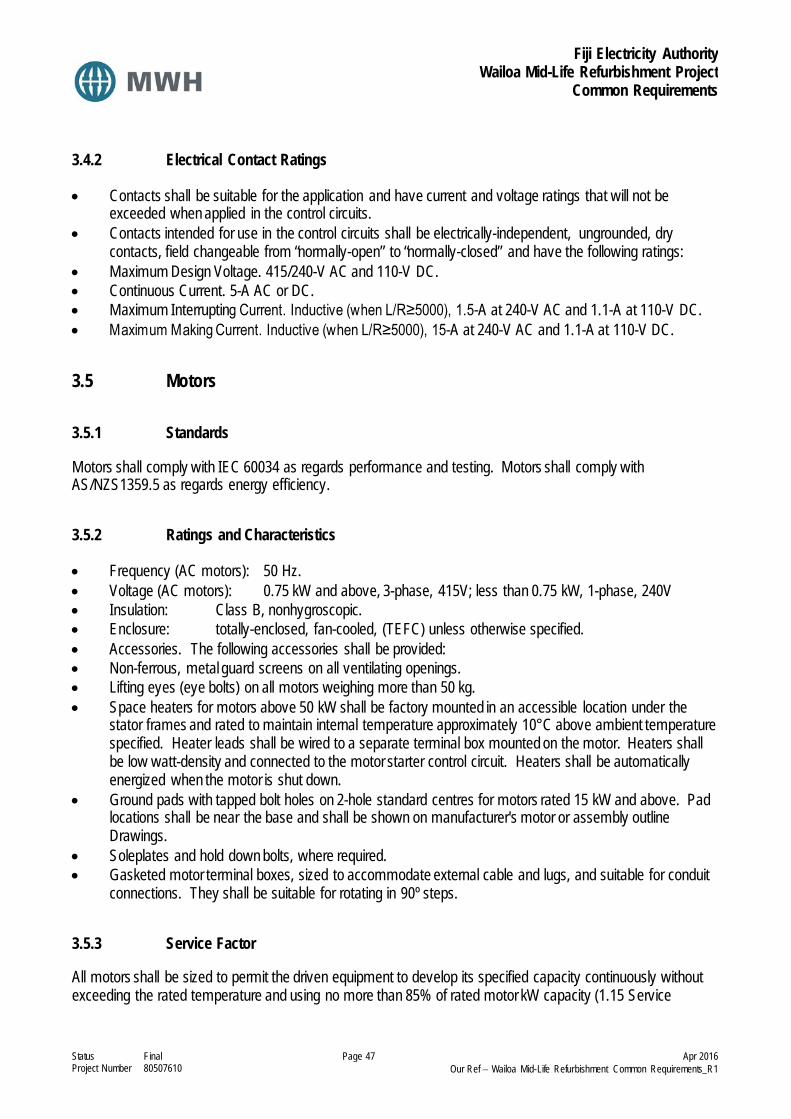
Fiji Electricity Authority Wailoa Mid-Life Refurbishment Project
Common Requirements
Status Final Page 47 Apr 2016 Project Number 80507610 Our Ref − Wailoa Mid-Life Refurbishment Common Requirements_R1
3.4.2 Electrical Contact Ratings
• Contacts shall be suitable for the application and have current and voltage ratings that will not be exceeded when applied in the control circuits.
• Contacts intended for use in the control circuits shall be electrically-independent, ungrounded, dry contacts, field changeable from “normally-open” to “normally-closed” and have the following ratings:
• Maximum Design Voltage. 415/240-V AC and 110-V DC. • Continuous Current. 5-A AC or DC. • Maximum Interrupting Current. Inductive (when L/R≥5000), 1.5-A at 240-V AC and 1.1-A at 110-V DC. • Maximum Making Current. Inductive (when L/R≥5000), 15-A at 240-V AC and 1.1-A at 110-V DC.
3.5 Motors
3.5.1 Standards
Motors shall comply with IEC 60034 as regards performance and testing. Motors shall comply with AS/NZS1359.5 as regards energy efficiency.
3.5.2 Ratings and Characteristics
• Frequency (AC motors): 50 Hz. • Voltage (AC motors): 0.75 kW and above, 3-phase, 415V; less than 0.75 kW, 1-phase, 240V • Insulation: Class B, nonhygroscopic. • Enclosure: totally-enclosed, fan-cooled, (TEFC) unless otherwise specified. • Accessories. The following accessories shall be provided: • Non-ferrous, metal guard screens on all ventilating openings. • Lifting eyes (eye bolts) on all motors weighing more than 50 kg. • Space heaters for motors above 50 kW shall be factory mounted in an accessible location under the
stator frames and rated to maintain internal temperature approximately 10°C above ambient temperature specified. Heater leads shall be wired to a separate terminal box mounted on the motor. Heaters shall be low watt-density and connected to the motor starter control circuit. Heaters shall be automatically energized when the motor is shut down.
• Ground pads with tapped bolt holes on 2-hole standard centres for motors rated 15 kW and above. Pad locations shall be near the base and shall be shown on manufacturer's motor or assembly outline Drawings.
• Soleplates and hold down bolts, where required. • Gasketed motor terminal boxes, sized to accommodate external cable and lugs, and suitable for conduit
connections. They shall be suitable for rotating in 90º steps.
3.5.3 Service Factor
All motors shall be sized to permit the driven equipment to develop its specified capacity continuously without exceeding the rated temperature and using no more than 85% of rated motor kW capacity (1.15 Service

Fiji Electricity Authority Wailoa Mid-Life Refurbishment Project
Common Requirements
Status Final Page 48 Apr 2016 Project Number 80507610 Our Ref − Wailoa Mid-Life Refurbishment Common Requirements_R1
Factor). The intent of this requirement is that the motor kW capacity be sized above the maximum continuous duty required by the driven equipment.
3.5.4 Bearings
• Bearings shall be liberal in size, suitable for continuous service under the conditions specified, sealed against the entrance of dirt and the escapement of the lubricant.
• Fitted openings shall be provided on the bearing housing for applying and draining the lubricant. Filler and drain extensions shall be furnished where necessary to give ready accessibility.
• Wherever necessary, the bearings shall be insulated to prevent the passage of shaft currents through the bearings.
• The thrust bearing for vertical motors shall be of the antifriction type, capable of supporting the weight of the motor and driven equipment rotating parts plus hydraulic thrust due to load. Bearings shall be grease lubricated with provisions for greasing. Provisions shall be made to prevent over-greasing where excess lubrication may cause damage.
3.5.5 Starting
• Except where specifically indicated otherwise, motors shall be suitable for full-voltage, across-the-line starting.
• Motors shall accelerate the driven equipment to rated speed with 80% of the motor nameplate voltage applied at the terminals. Unless otherwise approved, the maximum starting current shall not exceed 6 times the rated full-load current.
• Motors shall withstand without adverse effects, a full voltage, dead-bus transfer from one source to another. The minimum “dead time” for this transfer shall be considered to be 1 second.
• Where repetitive starting is necessary, the permissible number of starts shall be clearly indicated on the nameplate.
3.5.6 Finish
Motors for use indoors shall have the manufacturer's standard finish unless otherwise specified. Motors for outdoor use shall have corrosion-resisting hardware and corrosion-resisting finish on the rotor and shaft.
3.6 Cabling Installation Practice
3.6.1 General
All cables shall be run parallel to walls and either truly vertical or horizontal as appropriate. Agree all exposed cable routes with the Engineer prior to commencing work. All holes through structural members shall be approved by the Engineer before drilling commences. Ensure that all cables are supported to avoid undue strain on cables or on terminations. All cabling shall be neatly dressed, run in single layers and identified as to function at terminating points. All cabling shall be installed in a manner which permits its convenient withdrawal and replacement. No cable shall be cast directly into concrete.

Fiji Electricity Authority Wailoa Mid-Life Refurbishment Project
Common Requirements
Status Final Page 49 Apr 2016 Project Number 80507610 Our Ref − Wailoa Mid-Life Refurbishment Common Requirements_R1
Sharp edges to steel or sheet metal shall be removed and such work shall be arranged to avoid accidental injury to personnel, or damage to insulation. Provide insulated bushes at all points where cables enter metal enclosures.
3.6.2 Cable Identification
Each cable shall be labelled with a permanent identification number as indicated on the Contractors cable schedules. All cable cores shall be numbered.
3.6.3 Underground Cables
All underground cables are to be buried in a trench at a minimum depth of 600mm, bedded on not less than 100mm of fine washed sand and covered by a further 100mm of sand. The cables are to be laid free of kinks and twists and laid in flat formation without interlacing. The trench shall be backfilled with 150mm of soil, consolidated and a protective layer of 150 x 25 RS ground retention tanalith treated timber, or approved proprietary cable protection covering is to be placed over the full length of the trench. Cabling is to be completed covered by timber or equal protection. Lay on Orange PVC signal strip 100mm wide with “Electric cable below” or equal labelling, above cables over fully length of route, at a depth of 250mm. Locations of underground cables are to be accurately marked on the Contract drawings. Where underground cables enter building a warning sign indicating “danger buried cable” is to be fastened to the building 200mm above ground level.
3.6.4 Cable Ladder
Provide all necessary cable ladder to support cables. All cable ladder width shall be sufficient for the work plus 30% spare capacity. Cable ladder shall be manufactured from aluminium and shall be of NEMA 12A type. Cable ladder shall be stood off the wall on galvanised spacers or brackets or suspended from the ceiling on purpose made angle iron brackets galvanised after fabrication. Maximum spacing of supports, brackets and hangers shall be 2 meter. Cable ladder shall be capable of supporting 12.5 kg/m per 100mm, i.e. a 600mm wide cable ladder must be capable of supporting 75 kg/m. All runs of ladders shall be continuously bonded and earthed. For all HV cabling, proprietary cable clamps must be used. Ladders shall not be mounted directly onto flat surfaces. Install on suitable brackets clear of the surface to allow for cleaning and sufficient space for air circulation around and through the ladders.

Fiji Electricity Authority Wailoa Mid-Life Refurbishment Project
Common Requirements
Status Final Page 50 Apr 2016 Project Number 80507610 Our Ref − Wailoa Mid-Life Refurbishment Common Requirements_R1
3.6.5 Cable Installation Practice (HV Cables)
i General Single core cables shall be laid in trefoil formation using approved trefoil clamps at intervals of no more than 1m. All cables shall be pulled, supported and terminated in accordance with manufacturer’s instructions. All copper wire screens and steel wire armour shall be bonded and earthed at both ends. Joints in cable runs shall not be permitted (except for the aerial bundled conductor line). All exposed cables shall be run parallel to walls and either truly vertical or horizontal as appropriate. Cables to transformers may be supported as necessary using galvanised saddles fixed to the equipment frame but on no account shall penetrations be made in tanks containing oil. ii Terminations At termination boxes cables shall be glanded. All terminations shall use compression terminals. The Contractor shall ensure that: a. All cables shall be glanded using stainless steel glands incorporating a waterproofing seal. All terminations
shall use pressure crimp lugs, compressed using the correct tool. b. Glanding and termination of cable is carried out strictly in accordance with manufacturer’s instructions. c. All bolts used in termination shall be stainless steel fitted with plain washer and two nuts. The torque of all
bolted connections for cables over 70mm2 shall be recorded. d. PVC shrouds are fitted to outdoor cables and/or that any future creepage will not leave armouring exposed.
e. Two locknuts are fitted to each gland and that each gland is fitted to a gland plate or bracket.
f. Bushes are fitted on each gland.
g. Cable glands and cable sheaths are effectively connected to the earthing system. Earth connections must
have a cross section not less than 50% of the cross section of a core of the associated cable. h. Under no circumstances shall copper and aluminium conductors be directly connected.
3.6.6 Cabling Installation Practice (LV Cables)
i. General
Fiji Electricity Authority Wailoa Mid-Life Refurbishment Project
Common Requirements
Status Final Page 51 Apr 2016 Project Number 80507610 Our Ref − Wailoa Mid-Life Refurbishment Common Requirements_R1
All exposed cables shall be run parallel to walls and either truly vertical or horizontal as appropriate. Cables shall be run on either cable ladder or floor ducts as appropriate. Cables shall be sized to achieve a voltage drop of less than 2.5% of the nominal voltage between the distribution board and fitting. The maximum voltage drop from the station services transformers to the final sub circuit shall be no more than 5%. Ensure that all cables are supported to avoid undue strain on cables or on terminations. All cabling shall be neatly dressed, run in single layers and identified as to function at terminating points. All cabling shall be installed in a manner which permits its convenient withdrawal and replacement. No cable shall be cast directly into concrete. In such areas install cables in conduit or ducting. Draw wires shall be installed in conduits or pipes where necessary for later cable installation. Sharp edges to steel or sheet metal shall be removed and such work shall be arranged to avoid accidental injury to personnel, or damage to insulation. Provide insulated bushes at all points where cables enter metal enclosures. After installation but before connection, all power cables shall be tested for insulation resistance. Cabling shall be cleated at centres not exceeding:-
: 450 mm horizontally : 900 mm vertically On no account shall plastic sheathed cables be run in any situation where timbers have been treated or likely to be treated with tar-oil, creosote or allied products. No ordinary grade PVC insulated cables shall be run in any location where the temperature is likely to exceed 45oC. No high temperature grade PVC shall be run in locations where the temperature is likely to exceed 75oC. Mineral insulated cable shall be used where the temperature may exceed 75°C. Wiring which supplies equipment liable to overheat and cause rapid deterioration of the wiring, shall have the tails made off with heat resisting sleeves to protect the permanent wiring in a conduit box. The conduit box shall be fitted with terminals and mounted adjacent to the fitting or equipment with a run of heat resistant cabling from the box.
3.6.7 Cable Installation Practice (Instrumentation Cables)
The following installation practice shall be used: Cable shields shall be electrically continuous. When two lengths of shielded cable are connected together at a terminal block, an insulated point on the terminal block shall be used for connecting the shields. Shields shall be isolated and insulated except at their selected grounding point to prevent stray and multiple grounds to the shield. At the point of termination, the shield shall not be stripped back any further than necessary from the terminal block. For signal circuits, the shield must not be part of the signal circuit.

Fiji Electricity Authority Wailoa Mid-Life Refurbishment Project
Common Requirements
Status Final Page 52 Apr 2016 Project Number 80507610 Our Ref − Wailoa Mid-Life Refurbishment Common Requirements_R1
Signal circuits shall be grounded at only one point. Digital signal circuits shall be grounded only at the power supply. Analogue signal circuits shall be grounded only at the control panel and on a clean earth. Analogue signal cables shall be physically segregated from all power and control cables and from unshielded cables carrying digital or pulse type signals.
3.7 Cable Selection
3.7.1 240/415V Cables
Cables shall be a minimum of 600/1,000 volt rating for 415 line voltage use. All low voltage power cables shall have stranded copper conductors, shall be installed in accordance with AS/NZS 3000 and shall be rated in accordance with AS/NZS 3008.1.2.. Cables shall comply with the following standards:- PVC insulated : NZS 6401 : AS/NZS 4961 : AS/NZS 5000.1 XLPE insulated : AS/NZS 5000.1 : AS/NZS 4026 : AS/NZS 4961 Neutral Screened : AS/NZS 3155
3.7.2 Instrumentation Cabling
Type. Twisted pairs or triads (RTD's) with an overall shield. Conductor Stranded, tinned copper, 0.5 mm2 or larger. Insulation Type PVC Rated Voltage (not less than) 150V DC Continuous operating temperature 105°C (dry)
The insulated conductors shall have an overall aluminium foil shield bonded to a mylar or polyester film with a stranded, tinned copper, continuous drain wire outside of the shield. Each pair/triple wire shall be marked with indelible numbering.
Fiji Electricity Authority Wailoa Mid-Life Refurbishment Project
Common Requirements
Status Final Page 53 Apr 2016 Project Number 80507610 Our Ref − Wailoa Mid-Life Refurbishment Common Requirements_R1
3.7.3 Control Cabling
Type Unarmoured, circular, multicore with an integral earth conductor.
Conductor Stranded, copper, 1.5 mm2 or larger. Insulation Type PVC Rated Voltage (not less than) 1000-V AC Continuous operating temperature 90°C
Each core shall be marked with indelible numbering.
3.8 Earthing and Equipotential Bonding
Effective protective earthing and equipotential bonding shall be provided, in accordance with the Fijian Electricity Act and AS/NZS 3000, for all electrical equipment installed under this contract. The Contractor must ensure all metal work encasing electrical work is bonded to earth. This shall include bonding all trays, ladders, trunking and electrical equipment.
3.8.1 Building Structure
The building structural reinforcing, metal cladding, metal roofing, metal doors, hand railing and supporting steel work shall be securely bonded. Connections to the building reinforcing are to be made at 5m intervals. Connections to the foundation reinforcing must be made via a copper strip brazed to the reinforcing.
3.8.2 External Foundation Pads
Earthing of reinforcing of small external foundation pads of size less than or equal to 2 x 2m is not required. However, steel reinforcing of larger pads shall be bonded with the earth mat at two points to provide equipotential bonding.
3.8.3 External Fencing
All metallic fence supports and wire mesh shall be securely bonded. Each section of the fence shall be earthed using 16 x 2.5mm copper strap and long sections of the fence shall be earthed at intervals not greater than 20m. Earthing terminals shall be provided on metal fence posts by welding a lug with 2 x 14mm dia. holes at 50mm vertical centres. The lug shall be located on the inside of the fence.

Fiji Electricity Authority Wailoa Mid-Life Refurbishment Project
Common Requirements
Status Final Page 54 Apr 2016 Project Number 80507610 Our Ref − Wailoa Mid-Life Refurbishment Common Requirements_R1
3.9 Panel Construction
3.9.1 Metalwork
All enclosures used to house electrical equipment shall be gasketed, vermin proof and protected to the class specified in accordance with AS/NZS IEC 60947-1. The maximum height above floor level of all instruments, control switches and relays shall allow for easy operation of the plant and shall not exceed 1.80 m. Enclosures shall consist of rigid, self-supporting, steel panels with a minimum thickness of 1.5 mm steel that have full-length, hinged and gasketed doors, located to provide easy access to the equipment. A tamper-proof lock shall be provided on each door of the enclosure. Interior panels shall be provided inside the enclosures for mounting items of electrical equipment. All panels shall be located on a 75mm high plinth made of steel or concrete, as applicable to the general construction. Panels inside a switchroom or other outdoor enclosure that affords the same protection as a switchroom may be made of coated mild steel sheet construction. Steel shall be passivated, powder coated finished with baked enamel paint. Panels housed within an outdoor weatherproof enclosure shall be multi-compartmented with a compartment for each functional unit. All fastenings shall be integral with the panel or door and provision made for locking. Doors shall be rigid and fitted with weatherproof sealing material suitable for the climatic conditions specified. No door shall be wider than 1200mm without the permission of the Engineer. Panel positions in general and door sizes and positions when open, shall not impinge on the safety and operability requirements of these clauses. Outdoor panels shall be well ventilated through vermin-proof louvres comprising a filter screen attached to a frame and secured to the inside of the panel. Divisions between compartments within the panel shall be perforated to assist air circulation. If required, ventilation fans shall be used.
3.9.2 Terminals
Panel, including all terminations and other current carrying parts shall have a minimum IP rating of 2X with the panel doors open. All terminals shall be mounted in accessible positions. Adjacent terminals shall be adequately spaced to each other and to the incoming cable gland plate. Separate terminations shall be provided on each terminal strip for the cores of incoming and outgoing cables including all spare cores. All terminals having a circuit voltage of 240V or higher shall be separated from lower voltages by a space created with partitions or end plates combined with end brackets and shall be shielded with an insulated cover marked with a warning notice "Danger ..... Volts". Where necessary, the different 240V / 415V phases shall be shielded from each other with partitions (i.e. where the in-service or under-maintenance breaking of a phase-wire can result in a phase to phase short circuit due to the type of terminal used).

Fiji Electricity Authority Wailoa Mid-Life Refurbishment Project
Common Requirements
Status Final Page 55 Apr 2016 Project Number 80507610 Our Ref − Wailoa Mid-Life Refurbishment Common Requirements_R1
Terminal blocks shall not be located less than 200mm from cable gland plates. Only one conductor shall be terminated in each side of the terminal block. Shorting straps shall be used between terminal blocks to bridge identical conductor terminals. Cubicles shall have at least 10% spare terminals and enough extra space on mounting bars for another 20% terminals.
3.9.3 Neutral & Earth Bars
These shall be a generous size to enable convenient termination of all neutral and earth conductors. Neutral and earth bars shall be provided with purpose made terminations sufficient for all connections with 25% spare. The bars shall be brass, tunnel type with slotted grub screw termination fixing and shall be rated at not less than the full current carrying capacity of the main supply. Terminations are to be provided for incoming neutral and earth cables of sizes shown on the drawings or as required by AS/NZS 3000. Busbars and connected circuits shall be capable of carrying continuously a total load equal to the rated capacity of the incoming switch isolator without the temperature rise of any component mounted with or on a board exceeding 20°C. The earth and neutral bar shall be located well clear of incoming cables and other connections.
3.9.4 Busbars & Connections
Busbars and connections thereto shall be fully insulated and shall comply with AS/NZS 3439.2. Busbars shall be capable of carrying the continuous rated current with a maximum temperature rise of 30°C above an ambient temperature of 40°C. Clearances are to be maintained when a current equal to the specified short circuit rating is flowing in the busbars and connections and shall be capable of withstanding the specified test voltages. Busbars shall be rated at not less than the maximum current rating as indicated on the drawings and braced to withstand fault levels, which can be safely cleared by the section isolators.
3.9.5 Fuses
Fuses shall be high rupturing capacity and type gG as defined in IEC 60269-1, IEC 60269-2-1 and have minimum breaking capacities equal to 80kA or greater. Fuses to be used for motor protection may be type aM. In any case fuses shall have a minimum interrupting volt-ampere capacity at least equal to the fault rating at the switchboard specified herein.

Fiji Electricity Authority Wailoa Mid-Life Refurbishment Project
Common Requirements
Status Final Page 56 Apr 2016 Project Number 80507610 Our Ref − Wailoa Mid-Life Refurbishment Common Requirements_R1
Fuse ratings and the phase to which they are connected are to be legibly marked on holder and base. Provide (6) spare fuse links of each size and type used on the switchboard and locate in a purpose made compartment. Provide all spare fuse bases as indicated.
3.9.6 Miniature Circuit Breakers (MCBs)
Miniature circuit breakers (MCBs) shall be the trip-free type category “C” with instantaneous release under heavy fault conditions. They shall comply fully with AS/NZS 60898.1 and be mounted to be removable without removing adjacent circuit breakers. Circuit breakers shall have a fault rating of not less than the fault level of the distribution system at the point of connection in the switchboard but not less than 10kA. A minimum of 25% spare ways shall be provided to allow for the future MCBs.
3.9.7 Moulded Case Circuit Breakers (MCCBs)
Moulded case circuit breakers shall comply with AS/NZS IEC 60947-2. The ultimate breaking capacity of the circuit breakers shall be at least equal to the prospective fault level at the point of the distribution system where the breakers are installed. The service breaking capacity shall be 100% of the ultimate breaking capacity. The breakers shall be operated by a toggle, which shall clearly indicate the three fundamental positions ON and OFF and TRIPPED. For breakers up to 250A, each MCCB shall be fitted with an interchangeable trip unit incorporating a bi-metallic element for overload protection and magnetic protection for short-circuit. MCCBs above 250A shall be provided with an interchangeable electronic trip unit. In all cases a range of adjustable settings shall be provided on the trip unit.
3.9.8 Relays
All relays are to be of best quality with contacts rated for a continuous duty of not less than 10A. They shall be encased in hermetically sealed enclosures and shall be free from discernible noise when energised. Auxiliary contacts are to be self-cleaning.
3.9.9 Contactors
All contactors are to be of best quality with contacts rated for a continuous duty of not less than 16A. They shall be free from discernible noise when energised.

Fiji Electricity Authority Wailoa Mid-Life Refurbishment Project
Common Requirements
Status Final Page 57 Apr 2016 Project Number 80507610 Our Ref − Wailoa Mid-Life Refurbishment Common Requirements_R1
3.9.10 Isolators
Every functional unit shall be provided with effective means of isolation. All live side terminals of these isolators shall be shrouded to prevent accidental contact. Isolators shall be rated for the continuous load current and for the maximum fault duty, which may be reached. Isolators shall not be smaller than sizes shown on the drawings. Isolators shall be capable of being locked in the open or closed position. Isolators shall comply with AS/NZS IEC 60947-3 for AC 23 duty.
3.9.11 Pushbuttons and Pushbutton Switches
i. Type Pushbuttons and pushbutton switches shall be heavy-duty, oil-tight, complete with engraved legend plates, operators, and contact blocks. Legend plate engravings shall be selected by the Contractor and will be subject to the Engineer's approval. ii. Contact Ratings • Maximum Design Voltage. 500/300-V AC and 110-V DC. • Continuous Current. 10-A AC or DC. • Maximum Interrupting Current, Inductive. 3-A at 240-V AC and 2.2-A at 110-V DC. • Maximum Making Current, Inductive. 30-A at 240-V AC and 2.2-A at 110-V DC.
3.9.12 Control and Selector Switches
i. General Manually-operated switches provided and mounted on the front of switchboards and control cubicles shall be as specified herein. ii. Type Switches shall be heavy-duty, rotary type complying with the requirements of AS/NZS IEC 60947-5-1 for AC 11 duty. Ratings Maximum Design Voltage. 500/300-V AC and 240-V DC. Continuous Current. 10-A AC or DC. Maximum Interrupting Current, Inductive. 3-A at 240-V AC and 2.2-A at 110-V DC. Maximum Making Current, Inductive. 30-A at 240-V AC and 2.2-A at 110-V DC. iii. Escutcheon Plates Each switch shall be provided with an escutcheon plate clearly marked to show each operating position. Escutcheon plate markings shall be selected by the Contractor and will be subject to the Engineer's approval.

Fiji Electricity Authority Wailoa Mid-Life Refurbishment Project
Common Requirements
Status Final Page 58 Apr 2016 Project Number 80507610 Our Ref − Wailoa Mid-Life Refurbishment Common Requirements_R1
iv. Handles The type and colour of the switch handle shall be selected by the Contractor and will be subject to the Engineer's approval.
3.9.13 Electrical Digital and Analogue Indicating Instruments
3.9.13.1 Type and Construction Instruments shall be of the flush mounting type with non-reflecting glass. They shall be calibrated and suitable for the application. Electrical measuring instruments generally shall be 96 x 96 mm but may be 72 x 72 mm if approved by the Engineer. Analogue instruments shall be of the 270° full-scale deflection type. Digital instruments shall have the following features: • Bright orange LED display. • Minimum 4-digit, 12 mm-high, readout. • Black bezel with hardware and accessories for front-of-panel mounting. • 1% accuracy i. Standards Indicating instruments shall conform to IEC 60051, class index 1.5. ii. Scale Markings Scale markings shall be selected by the Contractor and will be subject to the Engineer's approval. Where instruments are connected to instrument transformer secondaries, the scale markings shall be selected to read the electrical quantities on the transformer primary.
3.9.13.2 Transducers and Transmitters Transducers and transmitters shall be suitable for accurately measuring the specified quantities. Outputs shall be a dc current signal ranging from 4 to 20-mA full scale, suitable for termination in a load resistance up to 750Ω. Unless specified otherwise, the maximum allowable error shall not exceed ±0.25% of full scale at 25°C, and the error resulting from a temperature variation between -20°C and 60°C shall not exceed ±0.5% of full scale. AC output ripple shall not exceed 1%. The units shall be provided with a 10% full scale calibration adjustment, and the response time shall be 400 ms or better from 0 to 99%. There shall be electrical isolation between input, output, external power supply if used, and the case ground connection. All transducers and transmitters shall have a dielectric test voltage rating conforming to IEC SWC test requirements.
3.9.13.3 Indicating Lamps i. Type Lamps shall be light emitting diode (led) type, 22.5mm diameter with press to test facility. ii. Ratings

Fiji Electricity Authority Wailoa Mid-Life Refurbishment Project
Common Requirements
Status Final Page 59 Apr 2016 Project Number 80507610 Our Ref − Wailoa Mid-Life Refurbishment Common Requirements_R1
The indicating lamps and resistors shall be rated to operate at 240-V AC or 24-V DC.
3.9.14 Motor Starters
Low voltage motor starters shall be of the combination type as defined in AS/NZS IEC 60947 - Part 4 and shall comprise: • Fused combination unit (disconnector and fuse switch) or moulded case circuit breaker (AC23 minimum
utilisation category). • AC contactor (AC3 minimum utilisation category). The operating mechanism of the isolating device shall be mounted on the front of the cubicle, operated by a pistol grip type handle. The mechanism shall be interlocked with the door to prevent opening when in the on position. The mechanism shall be padlockable in the off position. The rated operational current of the starter (Ie) shall be not less than the full-load current of the motor. The starter shall be rated for uninterruptible duty. Thermal overload relays shall be Type 3c as defined AS/NZS IEC 60947-4-1. Time/current characteristics shall be supplied, by the manufacturer, on 28mm x 56mm logarithmic decades. These curves shall have a tolerance not exceeding + 10%. Co-ordination of short circuit and overload protective devices shall be type 2 fully co-ordinated as defined in AS/NZS IEC 60947-4-1 for a prospective short-circuit current not less than the value determined by the electrical system design. For this purpose the short circuit protection device shall be fitted with the maximum rating of motor circuit fuse. Motor starters shall be suitable for both automatic and non-automatic methods of control. Unless otherwise specified, motor starter control circuits shall be operated from a 24V AC supply, derived from an individual, integral starter control transformer. Power factor correction capacitors shall be provided in motor starters to correct the motor power factor to a minimum of 0.93. Separate contactors shall be used to switch the motor circuit and power factor correction equipment. Where assisted start motor starters are required in order to reduce motor starting currents, electronic soft start units shall be used. Electronic soft start units shall be provided complete with bypass contactor. Assisted start operation shall be automatic changeover with adjustable time delays to suit the motor conditions. Contactors shall be provided with auxiliary contacts to provide all required control and signalling functions and shall be provided with two additional spare normally open and two spare normally closed contacts. Each starter shall be provided with the following controls and indications as a minimum:- • Door interlocked isolator.

Fiji Electricity Authority Wailoa Mid-Life Refurbishment Project
Common Requirements
Status Final Page 60 Apr 2016 Project Number 80507610 Our Ref − Wailoa Mid-Life Refurbishment Common Requirements_R1
• Running lamp. • Stopped lamp. • Fault lamp. • Run/off/auto selector switch, • Auto-control interposing relay 24V DC operated from plant control system. • Plant trips relay 24V DC operated from plant control system. • Ammeter. • Hours run meter. • Number of starts counter. • Emergency stop pushbutton. • Trips reset pushbutton. • Lamp test pushbutton. Each starter shall be provided with the following volt free contacts to provide interface with the plant control system:- • Running/stopped. • Machine available for auto control. • Fault. Each starter shall be provided with a test facility, which shall energise the control circuit when operated. The test switch shall be arranged to automatically release when the starter door is closed. The test facility shall enable the control circuits to be operated for testing purposes with the main motor circuit isolated. Each starter shall be provided with the facility to disconnect the controls via a remote emergency stop pushbutton. Where a pushbutton is not installed the connection facility shall still be provided, but linked out. All emergency stop operations shall require resetting by the starter/drive reset pushbutton to restart the machine. Each starter shall be provided with the facility to disconnect the controls via a remote early break contact on an isolator located adjacent to the motor. Where a motor is supplied with auxiliary protective devices (e.g. thermistor protection or moisture protection), the protective relays and associated controls shall be incorporated into the design of the starter. Control circuits shall be provided with a power on delay timer which shall make the starter available for automatic or manual control on restoration of the power supply without requiring operation of the reset pushbutton, unless another fault condition exists. Where a motor is supplied with an anti-condensation heater, an on/off switch shall be provided on the front of the starter to isolate the heater. The heater shall be switched via an auxiliary contact on the main contactor, operating so that the heater is energised whenever the motor is off.
3.9.15 Heaters
Enclosures containing electrical control and switching equipment shall be equipped with electric space heaters for moisture control. The construction of the enclosures and the placement of the heaters shall assure effective circulation of air and prevent damage to equipment by overheating. Heaters shall be rated 240-V AC, single-
Fiji Electricity Authority Wailoa Mid-Life Refurbishment Project
Common Requirements
Status Final Page 61 Apr 2016 Project Number 80507610 Our Ref − Wailoa Mid-Life Refurbishment Common Requirements_R1
phase. They shall be provided with thermostatically operated controls with “on-off” switches mounted inside the enclosure.
3.9.16 Lighting and Receptacles
Enclosures larger than 1.0 m2 (vertical, front-of-panel surface area) shall be provided with a light and receptacle inside the enclosure to facilitate operation and maintenance. The light shall be incandescent type, with wire-guard and “on-off” switch. The receptacle shall be a duplex type, 2-pole, 3-wire. Power supply to the light and receptacle will be from a single-phase, 240-V AC, circuit.
3.9.17 Panel Wiring
All panel wiring shall be carried out in a neat and systematic manner with cable supported clear of the panels and other surfaces at all points to obtain free circulation of air. All PVC insulated panel wiring shall comply with the requirements of BS 6231 Type BK. Conductors shall generally have a minimum cross section equivalent to 3/0.77mm (1.5mm²), 7/0.67mm (2.5mm²) but single stranded conductors should only be employed for rigid connections which are not subject to movement or vibration during shipment, operation or maintenance. Wire colours shall be as follows:
415V AC Red
A-phase connections in current and voltage transformer circuit only
415V AC White
B-phase connections in current and voltage transformer circuits only.
415V AC Blue C-phase connections in current and voltage transformer circuits only
415/240V AC Green with Yellow stripes
Connections to earth.
415/240V AC Black AC neutral connections, earthed or unearthed, connected to the secondary circuits of current and voltage transformers
240V AC Red Single phase AC connections other than those above
Positive Negative 24V DC Grey Pink 12V DC Purple Pink
Current Loops Purple Pink
24V AC Brown Phase wires 24V AC Orange Neutral wires
Provide segregation between LV and ELV outgoing terminals.

Fiji Electricity Authority Wailoa Mid-Life Refurbishment Project
Common Requirements
Status Final Page 62 Apr 2016 Project Number 80507610 Our Ref − Wailoa Mid-Life Refurbishment Common Requirements_R1
Wiring to doors shall be anchored at the panel side and sufficient length shall be provided to enable the door to swing fully open without strain on cabling. All wiring shall be identified with slip on ferrules with indelibly printed letters and numbers. All outgoing control / controlled field wiring shall be brought out to terminals to facilitate ease of termination. Termination of all wiring at these terminals shall be effected using pre-insulated crimped ferrules or lugs of the correct size to suit cable and terminal capacity. No wires may be teed or jointed between terminal points. Electrical wiring and instruments shall be so located that leakage of oil or water cannot affect them. Bus wiring between panels, cubicles, etc, shall be fully insulated and be completely segregated from the main panel wiring. All metallic cases of instruments, control switches, relays, etc, mounted in panels, steel or otherwise, shall be connected by means of green with yellow stripes PVC insulated copper conductors of not less than 2.5mm² cross section to the nearest earth bar.
3.9.18 Panel Earthing
All metallic cases of instruments, control switches, relays, etc, mounted in panels, steel or otherwise, shall be connected by means of green with yellow stripes PVC insulated copper conductors of not less than 2.5mm² cross section to the nearest earth bar. All metalwork shall be bonded to the main earth bar. All hinged panels shall be bonded with flexible copper. All cable sheaths and earthing conductors shall be bonded to the earth bar. Use compression type conductor lugs for all earth connections with bolted joints. Ensure that all connections are tightened. Earth continuity shall not depend upon metal joints. For panel earthing use starred washers between screw and panel.
3.9.19 Panel Labelling
All panels shall be fitted with an identification/rating plate displaying the following information: site name; rated voltage, phasing, frequency, current, etc; panel/equipment manufacturer; and contract number. All items, including exterior items, shall be identified with a white engraved laminate label with black lettering. All panel labels shall be fixed by two cadmium plated or stainless steel screws. The requirement for labels includes, but is not limited to, the following: • All panels, boxes, cabinets, cubicles or enclosures.
Fiji Electricity Authority Wailoa Mid-Life Refurbishment Project
Common Requirements
Status Final Page 63 Apr 2016 Project Number 80507610 Our Ref − Wailoa Mid-Life Refurbishment Common Requirements_R1
• Equipment mounted in or on the above items including relays, contactors, starters, sounders, motors, switches, sockets, controllers and luminaires.
3.10 Small Power requirements
3.10.1 Outlet Boxes
Each fixture or continuous row of fixtures and all switches, receptacles, and other wiring devices shall be provided with suitable outlet boxes. Boxes for use in dry locations shall be constructed of galvanized sheet steel. Covers shall be held in place with stainless steel screws. Boxes located outdoors shall be cast metal or alloy, fitted with screw-fastened covers and gaskets and with threaded conduit connections. Outlet box extension rings shall be provided for exposed conduit extensions from embedded outlet boxes. Extension rings shall match the embedded boxes. Where extension rings are mounted on cast type boxes, neoprene gaskets shall be used.
3.10.2 Receptacles and Switches
Duplex receptacles shall be 3-wire, grounding type, rated 20-A, 240-V AC, with ground connection wired to separate ground conductor in raceway. Switches used for the control of lighting fixtures shall be rated 20-A, 240-V AC, single-pole, two-pole, 3-way, or 4-way, as required. Wall switches and receptacles shall be covered with device plates suitable for the type and number of devices enclosed. Covers mounted on boxes containing 2 or more devices shall be of the combination type. Device plates shall be stainless steel in all indoor, dry locations. Device plates for duplex receptacles installed outdoors shall be provided with spring-type gasketed covers. Power outlets shall consist of one single gang receptacle integrally mounted with a safety switch. The safety switch and receptacle shall be interlocked so as to prevent the insertion or removal of a plug from the receptacle with the switch in the “ON” position. Both the switch and the receptacle shall be rated 415-V AC, 100 A. The safety switch shall be a heavy duty 3-pole switch with visible blades and a quick make-and-break mechanism. The receptacle shall be 3 phase, 4 wire grounded through the extra pole and shell. Power receptacle plugs shall be for 100-A service.
3.10.3 Fixtures
Fixtures shall be furnished complete with mounting brackets, fixture mounting stems, poles, or hangers, together with steel supports and/or channels as required, and fixture wires. All fixtures shall be subject to approval by the Engineer.

Fiji Electricity Authority Wailoa Mid-Life Refurbishment Project
Common Requirements
Status Final Page 64 Apr 2016 Project Number 80507610 Our Ref − Wailoa Mid-Life Refurbishment Common Requirements_R1
3.10.4 Ballasts
Ballasts shall be provided with fixtures as required and have a high power factor and shall be of required voltage and frequency.
3.10.5 Lamps
Lamps shall be furnished for all lighting fixtures. Lamps shall be of the required type, length, and wattage.
3.10.6 Lighting Panel Boards
Lighting panel boards shall be rated 415/240-V, 3-phase, 4-wire, 50 Hz, with 200-A (minimum) main bus and shall be provided with 3-pole main circuit breaker and 42 single-pole, 20-A branch circuit breakers. Each lighting cabinet shall consist of a panel board, box, and cover together with main circuit breaker, branch circuit breakers, buses, and other accessories as specified herein. They shall be of dead front construction. All lighting panel boards shall be the product of the same manufacturer and shall be completely built, assembled, and tested in the factory.
3.10.7 Lighting Contactor Cabinets
Lighting contactor cabinets shall be provided for manual/automatic control of outside lighting. The cabinets shall be furnished with all required equipment to make the installation complete.
3.10.8 Photocells
Photocells shall be furnished as required.
3.11 Switchboards
The Contractor shall submit layout and manufacturing drawings for all switchboards for review by the Engineer. The Contractor shall receive the Engineer’s comments before manufacture commences. The Contractor shall include all reasonable alterations required by the Engineer.
3.11.1 General
Switchboards are that part of the electrical installation as defined by AS/NZS3000. Switchboards may include control panel sections and distribution board sections. Control panel sections and distribution board sections shall be built to the same panel standard as the switchboard in which they are mounted. Distribution boards within switchboards shall otherwise agree with the Distribution Board section that follows. Assemblies shall be designed and built to comply with the following standards:

Fiji Electricity Authority Wailoa Mid-Life Refurbishment Project
Common Requirements
Status Final Page 65 Apr 2016 Project Number 80507610 Our Ref − Wailoa Mid-Life Refurbishment Common Requirements_R1
AS/NZS IEC 60947: Low-voltage switchgear and controlgear assemblies.
3.11.2 Metalwork
Panels shall be of rigid sheet metal construction and the minimum thickness of the sheets employed shall be 1.5 mm. The front of the panels shall have a smooth well-finished surface. Panels mounted indoors shall, as a minimum, be manufactured from coated mild sheet steel. The steel shall be passivated, powder coated and finished with baked enamel paint. Colour to be confirmed by Engineer.
3.11.3 Construction
Switchboards shall be cubicle types, flush front switchboard accommodating all equipment shown on the drawings and described herein. • Switchboards shall be Form 3a as a minimum. • Switchboards shall be IP 42 as a minimum. Switchboards shall be built up out of welded mild steel framework, fitted with removable sheet metal covers. Alternatives based on proprietary bolt-together frame-systems are subject to the approval of the Engineer. Steel covers shall be made from minimum 1.2mm material. All metal work shall be bonded to the earth bar. All connections shall be capable of being terminated without disconnecting other items and shall provide sufficient room for all required cable turns without exceeding cable minimum “during installation” and “set” radiuses as appropriate in each case. The switchboard shall have a separate steel-channel mounting base in a continuous length drilled for fixing to the floor with 10 mm diameter bolts. No door shall be wider than 800mm without the permission of the Engineer. Also refer to AS/NZS 3000 clause 2.9.8 “Location of Switchboards” and clauses 2.9.9 and 2.9.10. Panel positions in general and door sizes and positions when open, shall not impinge on the safety and operability requirements of these clauses. Starred washers shall be used to provide earth continuity between adjacent steel surfaces. Provide all necessary ventilation to ensure that heat build-up does not occur. Panels shall be well ventilated through vermin-proof louvers comprising a filter screen attached to a frame and secured to the inside of the panel. Divisions between compartments within the panel shall be perforated to assist air circulation, but not if this negates the section isolation requirements of AS/NZS 3439. If required to achieve satisfactory operating temperatures, thermostatically controlled ventilation fans shall be used.
3.11.4 Busbars and Connections
The main busbars shall be rated as required and braced to withstand fault levels as specified or 22kA rms for 1s, whichever is the larger. The busbar system shall be capable of withstanding thermal and magnetic stresses consistent with AS/NZS 3439.

Fiji Electricity Authority Wailoa Mid-Life Refurbishment Project
Common Requirements
Status Final Page 66 Apr 2016 Project Number 80507610 Our Ref − Wailoa Mid-Life Refurbishment Common Requirements_R1
Busbars and connections thereto shall be fully insulated. Clearances shall be maintained when a current equal to the specified short circuit rating is flowing in the busbars and connections, and must be capable of withstanding the specified test voltages. Bolted links shall be provided to allow for easy replacement of all current transformers. The design of busbars shall permit convenient future extension of the switchboard. Busbars shall be drilled, shall be copper and shall be fully tinned.
3.11.5 Neutral & Earth Bars
Neutral and earth bars shall be generously sized to enable convenient termination of all neutral and earth conductors. Busbars and connected circuits shall be capable of carrying continuously a total load equal to the rated capacity of the incoming switch isolator (or circuit breaker) without the temperature rise of any component mounted within or on a board exceeding 20°C. Neutral and earth bars shall be provided with purpose made terminations sufficient for all connections with 25% spare. The bars shall be brass, tunnel type with slotted grub screw termination fixing. Terminations shall be provided for incoming neutral and earth cables of sizes shown on the drawings or as required by the Regulations.
3.11.6 Moulded Case Circuit Breakers (MCCBs)
Moulded case circuit breakers shall comply with AS/NZS IEC 60947-2. The service breaking capacity (Ics) shall be 100% of the ultimate breaking capacity (Icu). The rated ultimate breaking capacity (Icu) of each moulded-case circuit breaker shall be equal to at least the value of the short-circuit current (Isc) at the point of installation on the electric circuit, unless the upstream circuit breaker makes it possible to ensure coordination as defined in Appendix A of AS/NZS IEC 60947-2. All MCCBs shall be designed for horizontal or vertical mounting without any adverse effect on electrical performance. It shall be possible to reverse feed the breaker without reduction in its performance. MCCBs shall be available in fixed, plug-in or withdrawable models and in 3 pole or 4 pole versions. MCCBs shall be of circuit breaker disconnector type. The breakers shall have a rated operational voltage of 690V AC (50/60Hz). The rated insulation voltage of the circuit breakers shall be 750V AC (50/60Hz). The MCCBs shall provide class II insulation (to IEC 664) between the front and internal power circuits. The operating mechanism shall be of the quick make quick break type, with the speed of operation independent of the operator, and shall be trip free.
Fiji Electricity Authority Wailoa Mid-Life Refurbishment Project
Common Requirements
Status Final Page 67 Apr 2016 Project Number 80507610 Our Ref − Wailoa Mid-Life Refurbishment Common Requirements_R1
The breakers shall be operated by a toggle or a handle as specified which shall clearly indicate the three fundamental positions ON, and OFF and TRIPPED. If required, rotary handles shall be fitted to the breaker. MCCBs of the same range shall have a common depth. The operating mechanism shall be designed in such a way that the position of the operating handle of the circuit breaker indicates the real position of the main contacts (i.e. positive contact indication), even if the circuit breaker is equipped with a rotary handle. Isolation shall be provided by a double break on the main circuit. It shall be possible to lock the circuit breaker in the isolated position only with the use of a locking device and padlocks. MCCBs shall have clearly accessible from the front face: • Markings of rating • Marked as suitable for isolation • Push-to-trip test button to test operation of poles • Contact position indicator The MCCB shall provide double insulation of the front face to allow on-site installation of auxiliaries without de-energising the installation or circuit. All electrical auxiliaries and accessories including voltage releases (shunt or under-voltage) and auxiliary contacts shall be designed for easy on-site installation. All electrical auxiliaries shall be equipped with terminal blocks and shall be of the snap-in type. All electrical auxiliaries shall be separated from power circuits and their addition shall not increase the MCCB volume. It shall be possible to fit the MCCB with a motor mechanism without affecting the circuit breaker characteristics.
3.11.6.1 Protection Function Each MCCB shall be provided with an integral trip unit that shall be easily interchanged with standard tools. The trip-setting area shall be able to be sealed off. All MCCBs shall include the option of, or be fitted standard with, an electronic trip unit. These shall be true RMS sensing and shall withstand temperatures of up to 125°C. For MCCBs up to and including 250A rating, standard trip units may be thermal-magnetic types, with at least 36 long-time current adjustments and pre-set short-time and instantaneous tripping. The optional electronic trip units shall provide as a minimum : • Long-time protection with 48 current threshold adjustments • Short-time protection with 8 current threshold adjustments • Pre-set instantaneous protection • 40A, 80A, 100A, 160A and 250A protection units.

Fiji Electricity Authority Wailoa Mid-Life Refurbishment Project
Common Requirements
Status Final Page 68 Apr 2016 Project Number 80507610 Our Ref − Wailoa Mid-Life Refurbishment Common Requirements_R1
For example, the 250A MCCB can be fitted with a 40A-body trip unit that provides 48 long-time current settings at and below 40A. For MCCBs above 250A rating and up to 630A, standard electronic trips shall provide as a minimum : • Long-time protection with 48 current threshold adjustments • Short-time protection with 8 current threshold adjustments • Pre-set instantaneous protection • 150A, 250A, 400A, and 630A protection units. For MCCBs above 250A rating and up to 630A, there shall also be an optional higher specified trip unit
available that offers, in addition to the above :
• Long-time tripping delay adjustments • Short-time tripping delay adjustments • Instantaneous protection with 8 current threshold adjustments • Instantaneous current threshold tripping delay adjustments • Indication of fault types • Optional communications capabilities with Modbus or other industry standard communications • Optional digital true RMS ammeter display For example, the 630A MCCB can be fitted with a 150A body trip unit that provides 48 long-time current settings at and below 150A.
3.11.6.2 Discrimination Function Discrimination shall be provided to comply with AS/NZS IEC 60947-2 and shall be total discrimination. This means that for faults from overloads up to the full prospective short circuit level of the system, only the circuit breaker immediately upstream of the fault shall operate to clear the fault and all other circuit breakers shall remain closed. The circuit breaker manufacturer may be asked by the Engineer to provide computer-generated calculations in the form of an easily read report that proves discrimination. In the short circuit region, the results shall be based on tests that the manufacturer has carried out that have been incorporated into computer model.
3.11.7 Miniature Circuit Breakers (MCBs)
Miniature circuit breakers (MCBs) shall comply fully with AS/NZS 4898. They shall be removable from the in-service position without removing adjacent circuit breakers and shall be of the trip-free type. The range available shall include breakers with B, C, D and MA tripping curves and shall be available in 6kA, 10kA and 15kA fault ratings. The breaker combinations of MCCB followed by MCB and further downstream MCBs shall provide full discrimination right through the circuit breaker installation.

Fiji Electricity Authority Wailoa Mid-Life Refurbishment Project
Common Requirements
Status Final Page 69 Apr 2016 Project Number 80507610 Our Ref − Wailoa Mid-Life Refurbishment Common Requirements_R1
MCBs shall have a fault rating of not less than the fault level of the distribution system at the point of connection in the switchboard but not less than 6KA. The use of cascading is permitted to provide an increase in a breaker’s fault rating. MCBs shall be capable of being padlocked open using suitable attachments. Spare MCBs shall be fitted as shown on the DB schedules. Blanking covers shall be fitted to all empty ways.
3.11.8 Cable Details
Cable access shall be from the top and from the bottom of the switchboard. Non-ferrous gland plates shall be fitted to each compartment for cable access. All cables shall be terminated via bolted compression type terminal lugs. Provide all necessary copper-work to facilitate this. Separation and insulation shall be provided between incoming and outgoing cable terminations.
3.11.9 Contactors
All contactors are to be of best quality with contacts rated for a continuous duty of not less than 16 amps (AC3).
3.11.10 Control Relays
All relays are to be of best quality with contacts rated for a continuous duty sufficient for the application. They shall be encased in sealed enclosures and shall be free from discernible noise when energised.
3.11.11 Control Wiring
All control panel wiring shall be carried out in a neat and systematic manner with cable supported clear of the panels and other surfaces at all points to obtain free circulation of air. Conductors shall generally have a minimum cross section equivalent to 3/0.77mm (1.5mm²), 7/0.67mm (2.5mm²) but single stranded conductors should only be employed for rigid connections which are not subject to movement or vibration during shipment, operation or maintenance. Wiring to doors shall be anchored at the panel side and sufficient length is to be provided to enable the door to swing fully open without strain on cabling. Full height doors shall be provided with door stays to prevent swinging when open. All panel doors shall be hinged and shall be provided with T’bar locks. At least one T’bar on each compartment shall be key lockable. The same key pattern shall be used for every lock on the whole assembly and a set of keys (minimum of 10) shall be provided with the assembly. All wires shall be number ferruled using Grafoplast, Critchley type K or Memocab type cable markers or other exactly equivalent system. Do not use industry standard ‘C’ and ‘D’ type ferrules. All outgoing control/controlled field wiring is to be brought out to terminals to facilitate ease of termination. All outgoing control / controlled field wiring is to be brought out to terminals to facilitate ease of termination.
Fiji Electricity Authority Wailoa Mid-Life Refurbishment Project
Common Requirements
Status Final Page 70 Apr 2016 Project Number 80507610 Our Ref − Wailoa Mid-Life Refurbishment Common Requirements_R1
Termination of all wiring at these terminals is to be effected using pre-insulated crimped ferrules or lugs of the correct size to suit cable and terminal capacity. No wires may be teed or jointed between terminal points. Bus wiring between panels, cubicles, etc, shall be fully insulated and be completely segregated from the main panel wiring. All wiring of different voltages shall be segregated. All metallic cases of instruments, control switches, relays, etc, mounted in panels, steel or otherwise, shall be connected by means of green with yellow stripes PVC insulated copper conductors of not less than 2.5mm² cross section to the nearest earth bar.
3.11.12 Selector Switches
Rotary selector switches shall comply with the requirements of AS/NZS IEC 60947-5-1 for AC 11 duty.
3.11.13 Terminals – Control Wiring
All terminals shall be mounted in accessible positions. Adjacent terminals shall be adequately spaced to each other and to the incoming cable gland plate. Separate terminations shall be provided on each terminal strip for the cores of incoming and outgoing cables including all spare cores. • Terminal blocks shall not be located less than 200 mm from cable gland plates. • Provide segregation between LV and ELV terminals. • Only one conductor shall be terminated in each side of the terminal block. • Shorting straps shall be used between terminal blocks to bridge identical conductor terminals. • AC supply connections shall be shielded at the terminal block by means of insulated covers. • Cubicles shall have space on mounting bars for at least another 20% terminals.
3.11.14 Earthing
Bond all metalwork to main earth bar. Bond all hinged panels with braided flexible copper.
3.11.15 Labels
Panel labels shall be provided to describe the operations of all devices to the Engineer’s approval. Labels shall consist of white lettering engraved on black traffolyte. Lettering shall be 12 mm high for main panel labels and 5 mm high for circuit descriptive labels. All labels shall be fixed with chromium plated or stainless steel screws. Each cubicle shall be provided with an engraved black and white designation label, and a typed or stencilled chart mounted inside the door giving full particulars of all circuits controlled. Cover chart with 1.6 mm clear Perspex fixed on a rigid frame. The chart shall show all circuit numbers and the location of circuit outlets.

Fiji Electricity Authority Wailoa Mid-Life Refurbishment Project
Common Requirements
Status Final Page 71 Apr 2016 Project Number 80507610 Our Ref − Wailoa Mid-Life Refurbishment Common Requirements_R1
Phases are to be identified by phase colours.
3.11.16 Manufacture
A recognised and approved manufacturer of switchboards, control panels and distribution boards shall be engaged to manufacture all panels.
3.12 Distribution Boards
The Contractor shall submit layout and manufacturing drawings for all distribution boards for review by the Engineer. The Contractor shall receive the Engineer’s comments before manufacture commences. All reasonable alterations required by the Engineer shall be included.
3.12.1 General
Distribution boards (DBs) may be included in switchboards to feed local final circuits, in which case the panel construction techniques are to comply with the switchboard requirements. Particular care is to be taken to ensure that adequate cable termination space is provided. Circuit description cards are required for each distribution board. These shall be typed and laid out in a way that clearly corresponds to the actual layout of the board. A copy of the circuit card shall be installed in a plastic sleeve mounted on the inside of the cabinet door and additional copies shall be placed in each Maintenance and Operation Manual.
3.12.2 Cabinet Construction
Provide sheet metal, enclosed type, fitted with lockable side hinged doors. They shall be folded 1.6 mm quality baked enamel finish internally and externally. The metalwork on the complete distribution board shall be thoroughly cleaned of all rusting, degreased and primed with zinc chromate. Internal colour is to be white. External colour as specified by the Engineer. Provide adequate terminal space on neutral and earth bars and adequate wiring space between DBs and ceiling and floor spaces to enable the addition of future sub-circuits up to the full capacity of the board. All metalwork shall be bonded to the earth bar and starred washers shall be used to provide earth continuity between adjacent steel surfaces. Boards shall be flush or surface mounted as indicated on the drawings. No handles shall protrude beyond the front cover/door. All mechanisms likely to rust shall be cadmium plated or otherwise rust proofed.

Fiji Electricity Authority Wailoa Mid-Life Refurbishment Project
Common Requirements
Status Final Page 72 Apr 2016 Project Number 80507610 Our Ref − Wailoa Mid-Life Refurbishment Common Requirements_R1
3.12.3 Busbars & Connections
Busbars shall be capable of carrying the continuous rated current with a temperature rise not exceeding 20°C above ambient. Clearances shall be maintained when a current equal to the specified short circuit rating is flowing in the busbars and connections, and shall be capable of withstanding the specified test voltages. Busbars shall be rated at not less than 100 amps each phase.
3.12.4 Circuit Breakers
MCCBs and MCBs shall agree with the requirements above for Switchboards.
3.12.5 Isolators
Every DB shall be provided with effective means of switch-isolation. All live-side terminals of these switches are to be shrouded to prevent accidental contact. Isolators shall be rated for the continuous load current and for the maximum fault level that may be reached. Isolators shall not be smaller than sizes shown on the drawings or schedules.
3.12.6 Manufacture
A recognised and approved manufacturer of switchboards, control panels and distribution boards shall be engaged to manufacture all panels.
3.13 Battery Charger Panel Construction
The Contractor shall supply a standard charger control panel that has been fully wired and tested at the manufacturer’s works. The panel shall be altered as required to agree with this specification. The control panels shall provide IP 42 or better in accordance with AS1939. Control panels shall consist of a single panel of rigid sheet metal construction and a minimum steel thickness of 1.2 mm. A hinged and tool-locked or key-locked door shall afford access to the panel and shall have a smooth well-finished surface. The panel shall be well ventilated through vermin-proof louvers comprising a filter screen attached to a frame and secured to the inside of the panel.

Fiji Electricity Authority Wailoa Mid-Life Refurbishment Project
Common Requirements
Status Final Page 73 Apr 2016 Project Number 80507610 Our Ref − Wailoa Mid-Life Refurbishment Common Requirements_R1
3.13.1 Control Panel Terminals
All terminals shall be mounted in accessible positions. Adjacent terminals shall be adequately spaced to each other and to the incoming cable gland plate. Separate terminations shall be provided on each terminal strip for the cores of incoming and outgoing cables. All terminals having a circuit voltage of 240 V or higher shall be shielded with an insulated cover marked with a warning notice “Danger Volts”. Only one conductor shall be terminated in each side of the terminal block. Shorting straps shall be used between terminal blocks to bridge identical conductor terminals. AC supply connections shall be shielded at the terminal block by means of insulated covers. Provide segregation between LV and ELV outgoing terminals.
3.13.2 Fuses
Fuses shall be high rupturing capacity type and have minimum capacities equal to that of class AC 80, Q1. They shall have a maximum fusing factor of 1.5 fusing. Fusing factors greater than 1.5 may be used for motor protection only with the approval of the Employer’s Representative.
3.13.3 Relays
All relays shall be of best quality with contacts rated for a continuous duty of minimum 10 amps. Auxiliary contacts are to be self-cleaning.