filler wires for gtaw process - 3.imimg.com · f c - mo codification : aws : er70s-a1...
TRANSCRIPT

FILLER WIRES FOR GTAW PROCESS

F 70 S2
CODIFICATION : AWS : ER70S-2
CHARACTERISTICS AND APPLICATIONS:F 70 S2 is triple deoxidized copper-coated mild steel wire available in bright finish, gives smooth flow, stable arc and spatter free under optimum welding conditions. It gives radiographic quality welds. Suitable for root run of mild steel pipes. Ideal for welding A36, A285 grade C, A515-55, A516-70, etc.
TYPICAL CHEMICAL COMPOSITION OF SOLID WIRE:Element C Mn Si P S Ti Zr AI Cu Ni Cr Mo% 0.05 1.25 0.55 0.02 0.02 0.10 0.09 0.09 0.06 0.10 0.10 0.10
TYPICAL MECHANICAL PROPERTIES OF ALL WELD METAL UTS YS Elongation CVN Impact strength
o(MPa) (MPa) (L=4d) % at -30 C (Joules)530 440 28.0 60
SHIELDING GAS : Argon for TIG welding, Argon/CO for MIG and CO 2 2
welding.
STANDARD WIRE : 1.2 mm and 1.6 mm diameter available in cut lengths.
Other diameter can be supplied on request.
PACKING : Cut lengths of 1000 mm and 500 mm.
Cut lengths supplied in 5 kgs.Coils in required weight.Robust cardboard cartons or plastic tubes.
APPROVALS : BV, PDIL, NPCIL
F 70 S2 (NACE)
CODIFICATION : AWS : ER70S-2
CHARACTERISTICS AND APPLICATIONS:F 70 S2 (NACE) is triple deoxidized copper coated mild steel wire available in bright finish, gives smooth flow, stable arc and spatter free under optimum welding conditions. It gives radiographic quality welds. Suitable for root run of mild steel pipes. Ideal for welding A36, A285 grade C, A515-55, A516-70, etc.
TYPICAL CHEMICAL COMPOSITION OF SOLID WIRE:Element C Mn Si P S Ti Zr AI Cu Ni Cr Mo% 0.05 1.25 0.55 0.010 0.008 0.10 0.09 0.09 0.06 0.10 0.10 0.10
TYPICAL MECHANICAL PROPERTIES OF ALL WELD METAL UTS YS Elongation CVN Impact strength at
o(MPa) (MPa) (L=4d) % minus 30 C (Joules)530 440 28.0 85
CORROSION TEST : Passes corrosion test as per NACE standard TM-01-77-96 (SSCC) and TM-02-84-96 (HIC)
HARDNESS OF WELD METAL : 200 HV5 Max.
SHIELDING GAS : Argon for TIG welding, Argon/CO for MIG and CO 2 2
welding.
STANDARD WIRE : 1.2 mm and 1.6 mm diameter available in cut
lengths. Other diameter can be supplied on request.
PACKING : Cut lengths of 1000 mm and 500 mm.
Cut lengths supplied in 5 kgs.Coils in required weight.Robust cardboard cartons or plastic tubes.

F C - Mo
CODIFICATION : AWS : ER70S-A1
CHARACTERISTICS AND APPLICATIONS:F C-Mo is a copper-coated solid wire available in bright finish, gives smooth flow, stable arc and spatter free under optimum welding conditions. It gives radiographic quality welds. It is ideally suited for welding of low alloy ferritic steels of similar composition. The weld metal possesses good high temperature properties. Typical applications include the welding of Carbon Molybdenum steels such as, ASTM Grade F1 of SA-182 & SA-336, Grade A of SA-204, Grade T1/T1a/T1b of SA-209, Grade WC1 of SA-217, Grade A of SA-302, Grade P1 of SA-335, Class 1 of A grades of SA-533, etc.
TYPICAL CHEMICAL COMPOSITION OF SOLID WIRE:Element C Mn Si S P Mo Cu% 0.06 1.2 0.45 0.010 0.012 0.55 0.10
TYPICAL MECHANICAL PROPERTIES OF ALL WELD METAL 0(UNDER ARGON GAS SHIELDING) : After PWHT at 620 C for 1 hour
UTS YS Elongation(MPa) (MPa) (L=4d) %560 450 25.0
SHIELDING GAS : Argon
CURRENT CONDITION : DCEN
WELDING POSITION : H, F, VU, OH
PACKING :
STANDARD SIZE 1.6 mm, 2.0 mm, 2.5 mm & 3.2 mm in cut lengths
of 500 mm / 1000 mm each.
QUANTITY 5 kg wire put in an airtight polythene bag and finally packed in a plastic container.Identification : Brand name & AWS code is punched on each wire.
FMn-Mo
CODIFICATION : AWS : ER80S-G
CHARACTERISTICS AND APPLICATIONS:F Mn-Mo is a copper-coated solid wire available in bright finish, gives smooth flow, stable arc and spatter free under optimum welding conditions. It gives radiographic quality welds. It is suitable for welding high strength fine-grained structural steels containing ~0.5%Mo. The wire is also suitable for welding of penstock pipe-line, fabrication of earth moving equipments, etc. where high tensile strength property is desired from the weld metal. Suitable for welding of ASTM steels: SA-455/ SA-455M, Gr.60, Gr.65 steels of SA-515/ SA-515M, Gr.60, Gr.65 steels of SA-516/ SA-516M, Class 1 of A, B, C, D grades of SA-533/ SA-533M, etc.
TYPICAL CHEMICAL COMPOSITION OF SOLID WIRE:Element C Mn Si S P Mo Cu% 0.06 0.55 0.53 0.010 0.015 0.50 0.15
TYPICAL MECHANICAL PROPERTIES OF ALL WELD METAL
(UNDER ARGON GAS SHIELDING) :UTS YS Elongation(MPa) (MPa) (L=4d) %640 540 23.0
SHIELDING GAS : Argon
CURRENT CONDITION : DCEN
WELDING POSITION : H, F, VU, OH
PACKING :
STANDARD SIZE 1.6 mm, 2.0 mm, 2.5 mm & 3.2 mm in cut lengths
of 500 mm / 1000 mm each.
QUANTITY 5 kg wire put in an airtight polythene bag and finally packed in a plastic container.Identification : Brand name & AWS code is punched on each wire.

F Cr-Mo 1
CODIFICATION : AWS : ER80S-B2
CHARACTERISTICS AND APPLICATIONS:F Cr-Mo 1 is a copper-coated solid wire available in bright finish, gives smooth flow, stable arc and spatter free under optimum welding conditions. It gives radiographic quality welds. It is suitable for welding 1.25Cr - 0.5Mo steel. The weld metal possesses good high temperature properties. It deposits notch free weld deposit with excellent mechanical properties. Especially suitable for welding of pipes & tubes of matching composition in Power plants, Refineries, Petrochemicals, Fertilizer plants, etc. Suitable for welding of ASTM steels: Grade F2, F11, F12 class 1 & 2 of SA-182, Grade T11of SA-199, Grade T2, T11 & T12 of SA-213, Grade WC6 of SA-217, Grade P2, P11 & P12 of SA-335, Grade FP2, FP11 & FP12 of SA-369, Grade 2, 11 & 12 of SA-387, Grade CP2, CP11 & CP12 of SA-426, etc.
TYPICAL CHEMICAL COMPOSITION OF SOLID WIRE:Element C Mn Si S P Cr Mo Cu% 0.08 0.50 0.55 0.010 0.012 1.30 0.55 0.10
TYPICAL MECHANICAL PROPERTIES OF ALL WELD METAL 0(UNDER ARGON GAS SHIELDING) : After PWHT at 620 C for 1 hour
UTS YS Elongation(MPa) (MPa) (L=4d) %620 550 24
SHIELDING GAS : Argon
CURRENT CONDITION : DCEN
WELDING POSITION : H, F, VU, OH
PACKING :
STANDARD SIZE 1.6 mm, 2.0 mm, 2.5 mm & 3.2 mm in cut lengths
of 500 mm / 1000 mm each.
QUANTITY 5 kg wire put in an airtight polythene bag and finally packed in a plastic container.Identification : Brand name & AWS code is punched on each wire.
F Cr-Mo 2
CODIFICATION : AWS : ER90S-B3
CHARACTERISTICS AND APPLICATIONS:F Cr-Mo 2 is a copper-coated solid wire available in bright finish, gives smooth flow, stable arc and spatter free under optimum welding conditions. It gives radiographic quality welds. It is suitable for welding 2.25Cr - 1Mo steel. The weld metal possesses good high temperature properties. It deposits notch free weld deposit with excellent mechanical properties. Especially suitable for welding of pipes and tubes of matching composition in Power plants, Refineries, Petrochemicals, Fertilizer plants, etc. Suitable for welding of ASTM steels: Grade F22 (class 1 & 3) of SA-182 and SA-336, Grade T4, T22 of SA-199, Grade T22 of SA-213, Grade WC9 of SA-217, Grade P22 of SA-335, Grade FP22 of SA-369, Grade 22, 22L of SA-387, Grade CP22 of SA-426, Grade 22 of SA-541, Class 1 of A, B types of SA-542, etc.
TYPICAL CHEMICAL COMPOSITION OF SOLID WIRE:Element C Mn Si S P Cr Mo Cu% 0.09 0.50 0.55 0.010 0.012 2.50 1.10 0.10
TYPICAL MECHANICAL PROPERTIES OF ALL WELD METAL 0(UNDER ARGON GAS SHIELDING) : After PWHT at 690 C for 1 hour
UTS YS Elongation(MPa) (MPa) (L=4d) %680 600 20
SHIELDING GAS : Argon
CURRENT CONDITION : DCEN
WELDING POSITION : H, F, VU, OH
PACKING :
STANDARD SIZE 1.6 mm, 2.0 mm, 2.5 mm & 3.2 mm in cut lengths
of 500 mm / 1000 mm each.
QUANTITY 5 kg wire put in an airtight polythene bag and finally packed in a plastic container.Identification : Brand name & AWS code is punched on each wire.

F Cr-Mo 5
CODIFICATION : AWS : ER80S-B6
CHARACTERISTICS AND APPLICATIONS:F Cr-Mo 5 is a copper-coated solid wire available in bright finish, gives smooth flow, stable arc and spatter free under optimum welding conditions. It gives radiographic quality welds. It is suitable for welding 5Cr-0.5Mo steel. The weld metal possesses good high temperature properties. The weld metal possesses excellent creep
0property up to 550 C. Especially suitable for welding of pipes and tubes of matching composition in Power plants, Refineries, Petrochemicals, Fertilizer plants, etc. Suitable for welding of ASTM steels: Grade F5/ F5a & F21 of SA-182, Grade T4, T22 of SA-199, Grade T22 of SA-213, Grade C5 of SA-217, Grade P22 of SA-335, Grade F5 & F21 (class 1&3) of SA-336, Grade FP5, FP21 of SA-369, Grade 5, 21 & 21L of SA-387, Grade CP5, CP21 of SA-426, Class 4, 4a of E types of SA-542, etc.
TYPICAL CHEMICAL COMPOSITION OF SOLID WIRE:Element C Mn Si S P Cr Mo Cu% 0.06 0.50 0.40 0.010 0.012 5.20 0.55 0.10
TYPICAL MECHANICAL PROPERTIES OF ALL WELD METAL 0(UNDER ARGON GAS SHIELDING) : (AFTER PWHT AT 750 C FOR 1
HOUR)UTS YS Elongation(MPa) (MPa) (L=4d) %600 520 25
SHIELDING GAS : Argon
CURRENT CONDITION : DCEN
WELDING POSITION : H, F, VU, OH
PACKING :
STANDARD SIZE 1.6 mm, 2.0 mm, 2.5 mm & 3.2 mm in cut lengths
of 500 mm / 1000 mm each.
QUANTITY 5 kg wire put in an airtight polythene bag and finally packed in a plastic container.Identification : Brand name & AWS code is punched on each wire.
F Cr-Mo 91
CODIFICATION : AWS : ER90S-B9
CHARACTERISTICS AND APPLICATIONS:F Cr-Mo 91 is a copper-coated solid wire yielding 9% Cr-1% Mo and modified with Niobium, Vanadium and Nitrogen designed to provide improved creep strength, toughness, fatigue life, oxidation and corrosion resistance at elevated temperatures. The wire gives stable arc, smooth welding performances and deposits radiographic quality welds. It is designed to weld the materials in power plant and refineries etc. Following are some of the steels that can be welded with this wire.I) Plate: A 387 Gr.91 (II) Pipes: A 335-P91 (III) Tubes: A 213 - T91
TYPICAL CHEMICAL COMPOSITION OF SOLID WIRE:Element C Mn Si P S Cr Ni Mo V Nb N AI% 0.11 1.10 0.30 0.01 0.01 9.35 0.90 1.00 0.20 0.03 0.03 0.01
TYPICAL MECHANICAL PROPERTIES OF ALL WELD METAL 0(UNDER ARGON GAS SHIELDING) : (AFTER PWHT AT 740 C FOR 1
HOUR)UTS YS Elongation CVN Impact strength at
o(MPa) (MPa) (L=4d) % 20 C (Joules)810 700 19.0 50
SHIELDING GAS : Argon
CURRENT CONDITIONS : DCEN
WELDING POSITION : H, F, VU, OH
PACKING :
STANDARD SIZE 1.6 mm, 2.0 mm, 2.5 mm & 3.2 mm in cut lengths
of 500 mm / 1000 mm each.
QUANTITY 5 kg wire put in an airtight polythene bag and finally packed in a plastic container.Identification : Brand name & AWS code is punched on each wire.

APPLICATIONNi OTHERS
10.6 - Su i tab le for we ld ing AISI 304 and s imi la r compositions.
10.6 - Ideal for welding similar ELC versions. The deposit possesses excellent corrosion resistance.
13.8 - For welding carbon steel to stainless steels, clad steels, etc.
13.8 - For welding carbon steels to low carbon stainless steels, clad steels, etc.
21.3 - For welding dissimilar steels, heat resistant castings, etc.
12.5 Mo : 2.3 For welding AISI 316 and similar compositions.
12.5 Mo : 2.3 For welding AISI 316L and similar composition. The depos i t possesses exce l l en t co r ros ion resistant.
13.1 Mo : 2.50 Deposits fully austenitic welds for excellent N : 0.13 resistance to corrosion especially in urea service.
9.5 Cb+Ta : 0.75 Deposits stabilized weld metal for welding stainless steels of type AISI 347, 321, etc.
9.5 Cb+Ta : 0.70 Ideal for welding stabilized, low carbon version of 18/8 type.
BRAND AWS TYPICAL CHEMICAL COMPOSITION OF WIRE (%)NAME CLASSIF- C Mn Si S P Cr
ICATION
STAINLESS STEELS
FW 308 ER308 0.040 1.20 0.34 0.010 0.016 20.0
FW 308 L ER 308L 0.025 1.20 0.34 0.010 0.016 20.0
FW 309 ER 309 0.050 1.75 0.35 0.010 0.020 23.3
FW 309 L ER 309L 0.020 1.75 0.35 0.010 0.020 23.3
FW 310 ER310 0.080 1.65 0.34 0.005 0.015 26.6
FW 316 ER316 0.040 1.50 0.50 0.010 0.012 19.5
FW 316L ER316L 0.020 1.50 0.50 0.010 0.012 19.5
FW 316L-LF - 0.020 1.87 0.34 0.010 0.012 18.5
FW 347 ER347 0.040 2.00 0.37 0.010 0.015 19.5
FW 347L ER347L 0.020 2.00 0.37 0.010 0.015 19.5
FILLER WIRES FOR GTAW PROCESS

APPLICATIONNi OTHERS
0.5 - For welding straight chromium stainless steels of similar composition.
0.5 - For welding ferritic stainless steels.
8.5 Mo : 3.0 For welding duplex stainless steels of the 22Cr-N :0.10 9Ni- 3Mo types such as UNS S31803
5.0 Mo : 3.2 For welding super duplex stainlessN : 0.15 steels having minimum 25%Cr.
63.8 Cu : 31.0 For welding monel to itself and to carbon steels.Ti : 2.56
96.2 Ti : 2.6 For welding nickel to itself and to carbon steels.
71.0 Fe : 2.5 For welding a range of Inconel 600,601, 690,Cb+Ta : 2.5 Incoloy 800, 800H, 800HT and 9% Nickel steel.
Used for dissimilar applications joining Inconel 600 or Incoloy 800 with carbon steels and stainless steels, also for 200 and 400 type alloys.
BRAND AWS TYPICAL CHEMICAL COMPOSITION OF WIRE (%)NAME CLASSIF- C Mn Si S P Cr
ICATION
FW 410 ER410 0.080 0.55 0.45 0.010 0.025 12.6
FW 430 ER430 0.050 0.50 0.40 0.010 0.025 16.2
FW 2209 ER2209 0.025 1.10 0.60 0.025 0.025 22.0
FW 2553 ER2553 0.030 1.10 0.60 0.025 0.030 25.0
NICKEL AND ITS ALLOYS
FW 1250 ERNiCu-7 0.025 0.87 0.16 0.006 0.010 -
FW 1280 ERNi-1 0.025 0.44 0.20 0.010 0.007 -
FW NiCr-3 ERNiCr-3 0.035 3.00 0.30 0.010 0.025 20.0
NOTE :SIZES AVAILABLE : Any standard size from 1.2 mm to
4.0 mm diameter.FORM : Cut lengths of 1000 mm or Coils
of required weight.PACKING : Cut lengths supplied in 5 kgs.
robust cardboard cartons.
FILLER WIRES FOR GTAW PROCESS

SOME COMMON ASME MATERIAL SPECIFICATIONS
STEEL TYPE TYPICAL CHEMICAL ANALYSIS
SPEC. C Mn Si Mo Ni
SA 36 Structural steel - - - - -
SA 202 Gr-A Cr-Mn-Si alloy plates 0.17 0.97-1.52 0.54-0.96 - -
B for pressure vessels 0.25 0.97-1.52 0.54-0.96 - -
SA 203 Gr-A Ni-alloy steel plates 0.17* 0.78* 0.13-0.45 - 2.03-2.57
B for pressure vessels 0.21* 0.78* 0.13-0.45 - 2.03-2.57
D 0.17* 0.78* 0.13-0.45 - 3.18-3.82
E 0.20* 0.78* 0.13-0.45 - 3.18-3.82
SA 204 Gr-A C-Mo alloy steel 0.18* 0.98 0.13-0.45 0.41-0.64 -
B plates for pressure 0.20* 0.98 0.13-0.45 0.41-0.64 -
C vessels 0.23* 0.98 0.13-0.45 0.41-0.64 -
SA285 Gr-A Low and intermediate 0.17 0.98 - - -
B tensile strength 0.22 0.98 - - -
C C-steel plates for 0.28 0.98 - - -
pressure vessels
SA 299 C-Mn-Si steel plates 0.28* 0.84-1.52* 0.13-0.45 - -
for pressure vessels
SA 302 Gr-A Mn-Mo-and 0.20* 0.87-1.41 0.13-0.45 0.41-0.64 -
B Mn- Mo-Ni alloy 0.20* 1.07-1.62 0.13-0.45 0.41-0.64 -
C steel plates for 0.20* 1.07-1.62 0.13-0.45 0.41-0.64 0.37-0.73
D pressure vessels 0.20* 1.07-1.62 0.13-0.45 0.41-0.64 0.67-1.03
SA 353 9% Ni steel double 0.13 0.98 0.13-0.45 - 8.4-9.6
normalized and
tempered for
pressure vessel
SA 387 Gr-2 Pressure vessels 0.21 0.50-0.88 0.13-0.45 0.40-0.65 -
12 plates, alloy steel, 0.17 0.35-0.73 0.13-0.45 0.40-0.65 -
11 Cr-Mo 0.17 0.35-0.73 0.44-0.86 0.40-0.70 -
22 0.15* 0.25-0.66 0.50 0.85-1.15 -
21 0.15* 0.25-0.66 0.50 0.85-1.15 -
5 0.15 0.25-0.66 0.55 0.40-0.70 -
OTHERS UTS (ksi) RECOMMENDED
Cr ELECTRODE
- - - Medio / Supratherme
0.31-0.64 - 75-95 Tensal
0.31-0.64 - 85-110 Tensal
- - 65-85 Nitherme 2.5
- - 70-90 Nitherme 2.5
- - 65-85 Nitherme 3.5
- - 70-90 Nitherme 3.5
- - 65-85 Molytherme
- - 70-90 Molytherme
- - 75-95 Molytherme
- - 45-65 Medio / Exobel (for T< 16 mm)
- - 50-70 Supratherme (for T > 16 mm)
- - 55-75
- - 75-95 Tensal
- - 75-95 Nimotherme-1/Molytherme- Extra
- - 80-100 Do
- - - 80-100 Nimotherme-1
- - 80-100 Nimotherme-1
- CVN Impact strength at 100-120 D&H 12120
-195 C and Lateral
expansion specified
Cl.1 / Cl.2
0.46-0.85 - 55-80 / 70-90 Cromotherme
0.74-1.21 - 55-80 / 65-85 Cromotherme-1
0.94-1.56 - 60-85 / 75-100 Cromotherme-1
1.88-2.62 - 60-85 / 75-100 Cromotherme-2
2.63-3.37 - 60-85 / 75-100 Cromotherme-2
4.00-6.00 - 60-85 / 75-100 Cromotherme-5
*Indicates variation with thickness

STEEL TYPE TYPICAL CHEMICAL ANALYSIS
SPEC. C Mn Si Mo Ni
SA 515 Gr 55 C-steel plates for 0.20* 0.98 0.13-0.45 - -
60 pressure vessels for 0.24* 0.98 0.13-0.45 - -
65 intermediate and higher 0.28* 0.98 0.13-0.45 - -
70 temperature service 0.31* 1.30 0.13-0.45 - -
SA 516 Gr 55 C-steel plates for 0.18* 0.54-0.98* 0.13-0.45 - -
60 pressure vessels for 0.21* 0.54-0.98* 0.13-0.45 - -
65 moderate and lower 0.24* 0.79-1.30* 0.13-0.45 - -
70 temperature service 0.27* 0.79-1.30* 0.13-0.45 - -
SA 517 Gr A High strength alloy 0.13-0.23 0.74-1.20 0.34-0.86 0.15-0.31 -
B steel plates, 0.13-0.23 0.64-1.10 0.13-0.37 0.12-0.28 -
D quenched and 0.11-0.22 0.35-0.78 0.08-0.45 0.12-0.28 -
E tempered for pressure 0.10-0.22 0.35-0.78 0.08-0.45 0.36-0.64 -
F vessels 0.08-0.22 0.55-1.10 0.13-0.37 0.36-0.64 0.67-1.03
J 0.10-0.23 0.40-0.78 0.18-0.37 0.46-0.69 -
P 0.10-0.23 0.40-0.78 0.18-0.37 0.41-0.64 1.15-1.55
SA 533 Gr A Mn-Mo and 0.25 1.07-1.62 0.13-0.45 0.41-0.64 -
B Mn-Mo-Ni alloy steel 0.25 1.07-1.62 0.13-0.45 0.41-0.64 0.37- 0.73
C plates Q&T for 0.25 1.07-1.62 0.13-0.45 0.41-0.64 0.67-1.03
D pressure vessels 0.25 1.07-1.62 0.13-0.45 0.41-0.64 0.17-0.43
SA 537 Cl 1 C-Mn-Si steel plates, 0.24 0.61-1.46* 0.13-0.55 - -
2 heat treated for 0.24 0.61-1.46* 0.13-0.55 - -
pressure vessels
SA 553 Gr I 8 &9% Ni alloy steel 0.13 0.98 0.13-0.45 - 8.4-9.6
II plates Q&T for pressure 0.13 0.98 0.13-0.45 - 7.4-8.6
vessels
SA 612 Pressure vessels plates 0.29* 0.92-1.46* 0.13-0.45* - -
C- steel, high strength,
for moderate and lower
temperature service
SA 645 5% Ni alloy steel plate 0.15 0.25-0.66 0.18-0.45 0.17-0.38 4.65-5.35
specially heat treated
for pressure vessels
OTHERS UTS ksi RECOMMENDED
Cr ELECTRODE
- - 55-75
- - 60-80
- - 65-85 Supratherme
- - 70-90
- - 55-75
- - 60-80
- - 65-85 Supratherme(Spl)
- - 70-90
0.46-0.84 Zr: 0.04-0.16
0.36-0.69 V: 0.02-0.09;Ti:0.01-0.04
0.79-1.26 Ti:0.03-0.11
1.34-2.06 Ti:0.03-0.11 115-135* Ultratensal-MH
0.36-0.69 V: 0.02-0.09,Cu:0.12-0.53
- -
0.79-1.26 -
- - C1 C2 C3
- - 80 90 100 Class 1: Nimotherme-1
- - to to to Class 2 : Tensal
- - 100 115 125 Class 3 : Ultratherme-H
- - 70-90 Supratherme(Spl)
- - 80-100 Supratherme-Ni(Spl)
- CVN Impact strengtho- at -195 C for type I
oand- 170 C for type II and 100-120 D&H 1212
lateral expn. specified
- - 83-105* Tensal / Ultratherme-H
- CVN Impact strength 95-115 D&H 1212o
- at -170 C and lateral expn.
Specified
*Indicates variation with thickness

C
HE
MIC
AL
AN
ALY
SIS
(%)
AIS
IC
Mn
Si
Cr
Ni
Oth
erR
ecom
men
ded
Typ
e N
o.E
lem
ents
Ele
ctro
de
20
10
.15
5.5
/7.5
1.0
16
/18
3.5
/5.5
N: 0
.25
Max
.R
utox
-A
20
20
.15
7.5
/10
.01
.01
7/1
94
/6N
: 0.2
5 M
ax.
Rut
ox-A
30
10
.15
2.0
1.0
16
/18
8/1
0-
Rut
ox-A
30
20
.15
2.0
1.0
17
/19
8/1
0-
Rut
ox-A
30
2B
0.1
52
.02
/31
7/1
98
/10
-R
utox
-A
30
40
.08
2.0
1.0
18
/20
8/1
2-
Rut
ox-A
30
4 L
0.0
32
.01
.01
8/2
08
/12
-R
utox
-B
30
50
.12
2.0
1.0
17
/19
10
/13
-R
utox
-A
30
80
.08
2.0
1.0
19
/21
10
/12
-R
utox
-A
31
00
.25
2.0
1.5
24
/26
19
/22
-D
&H
31
0-1
6
31
0S
0.0
82
.01
.52
4/2
61
9/2
2-
D&
H 3
10
-16
31
60
.08
2.0
1.0
16
/18
10
/14
Mo:
2.0
/3.0
Rut
ox-M
o
31
6L
0.0
32
.01
.01
6/1
81
0/1
4M
o :2
.0/3
.0R
utox
-D
31
70
.08
2.0
1.0
18
/20
11
/15
Mo:
3/4
Rut
ox-M
o(Ex
tra)
SO
ME
CO
MM
ON
AIS
I S
TA
IN
LE
SS S
TE
EL
S
C
HE
MIC
AL
AN
ALY
SIS
(%)
AIS
IC
Mn
Si
Cr
Ni
Oth
erR
ecom
men
ded
Typ
e N
o.E
lem
ents
Ele
ctro
de
31
7L
0.0
32
.01
.01
8/2
01
1/1
5M
o: 3
/4R
utox
-E3
21
0.0
82
.01
.01
7/1
99
/12
Ti :
5xC
Min
Rut
ox-A
(St)
34
70
.08
2.0
1.0
17
/19
9/1
3(C
b+T
a) :
Rut
ox-A
(St)
10
XC
Min
3
48
0.0
82
.01
.01
7/1
99
/13
(Cb+
Ta)
:R
utox
-A(S
t)1
0xC
Min
40
30
.15
1.0
0.5
11
.5/1
3-
-D
&H
-41
0/
D&
H-1
3C
r4
05
0.0
81
.01
.01
1.5
/14
.5-
Al:
0.1
0/0
.30
D&
H-4
10
/D
&H
-13
Cr
41
00
.15
1.0
1.0
11
.5/1
3.5
--
D&
H-4
10
/D
&H
-13
Cr
41
40
.15
1.0
1.0
11
.5/1
3.5
1.2
5/2
.50
-D
&H
-41
0/
D&
H-1
3C
r
42
00
.15
1.0
1.0
12
/14
--
D&
H-4
10
/
D
&H
-13
Cr
43
10
.20
1.0
1.0
15
/17
1.2
5/2
.50
-D
&H
-43
0/
D&
H-1
7 C
r5
01
0.1
01
.01
.04
/6-
Mo:
0.4
0/0
.65
Cro
mot
herm
e-5
50
20
.10
1.0
1.0
4/6
-M
o:0
.40
/0.6
5C
rom
othe
rme-
54
30
0.1
21
.01
.01
4/1
8-
-D
&H
-43
0/
D&
H-1
7C
r
No
te:
De
pe
nd
ing
on
ap
plic
ati
on
, th
e e
lect
rod
es
reco
mm
en
de
d ca
n va
ry.

ST
AN
DA
RD
CA
ST
IN
G
SP
EC
IF
IC
AT
IO
NS
DE
SIG
NA
TIO
N
GR
AD
E C
HE
MIC
AL
CO
MP
OS
ITIO
N(%
)
E
LEC
TR
OD
E
CM
nS
iN
iC
rM
oO
ther
s
A2
17
WC
10
.25
05
-0.8
0.6
--
0.4
5-0
.65
-M
olyt
herm
e
Mar
tens
itic
W
C4
0.2
00
5-0
.80
.60
.7-1
.10
.5-0
.80
.45
-0.6
5-
CN
M
stai
nles
s st
eel
WC
50
.20
0.4
-0.7
0.6
0.6
-1.0
0.5
-0.9
0.9
-1.2
-C
NM
& a
lloy
cast
ing
WC
60
.20
0.5
-0.8
0.6
-1
.0-1
.50
.45
-0.6
5-
Cro
mot
herm
e-1
for
pres
sure
WC
90
.18
0.4
-0.7
0.6
-2
.0-2
.75
0.9
0-1
.20
-C
rom
othe
rme-
2
cont
aini
ngC
50
.20
0.4
-0.7
0.7
5-
4.0
-6.5
0.4
5-0
.65
-C
rom
othe
rme-
5
part
s su
itab
le
C1
20
.20
0.3
5-0
.65
1.0
-8
.0-1
0.0
0.9
-1.2
0-
Cro
mot
herm
e-9
for
HT
serv
ice
C1
50
.15
1.0
1.5
0-
11
.5-1
4.0
0.5
-
D&
H 1
3C
r/D
&H
41
0
A7
43
CF
80
.08
1.5
2.0
8.0
-11
.01
8.0
-21
.0-
-R
utox
-A
Cor
rosi
onC
G-1
20
.12
1.5
2.0
10
.0-1
3.0
20
.0-2
3.0
--
Cro
nith
-25
/12
resi
stan
tC
F-2
00
.20
1.5
2.0
8.0
-11
.01
8.0
-21
.0-
-R
utox
-A
Fe-C
r,Fe
-Cr-
Ni
CF-
8M
0.0
81
.52
.09
.0-1
2.0
18
.0-2
1.0
2.0
-3.0
-R
utox
-Mo
& N
i bas
e al
loy
CF-
8C
0.0
81
.52
.09
.0-1
2.0
18
.0-2
1.0
-C
b st
abili
sed
Rut
ox-A
(St)
Cas
ting
for
CH
-20
0.2
01
.52
.01
2.0
-15
.02
2.0
-26
.0-
- C
roni
th-2
5/1
2
gene
ral
CK
-20
0.2
02
.02
.01
9.0
-22
.02
3.0
-27
.0-
-D
&H
31
0-1
6
appl
icat
ion
CE3
00
.03
1.5
2.0
8.0
-11
.02
6.0
-30
.0-
-D
&H
88
8
CA
15
M0
.15
1.0
0.6
51
.01
1.5
-14
.00
.15
-1.0
-D
&H
13
Cr
CF-
30
.03
1.5
2.0
8.0
-12
.01
7.0
-21
.0-
-R
utox
-B
Not
e: D
epen
ding
on
appl
icat
ion,
the
ele
ctro
des
reco
mm
ende
d ca
n va
ry.
DE
SIG
NA
TIO
N G
RA
DE
CH
EM
ICA
L C
OM
PO
SIT
ION
(%)
ELE
CT
RO
DE
CM
nS
iN
iC
rM
oO
ther
s
CF-
3M
0.0
31
.51
.59
.0-1
3.0
17
.0-2
1.0
2.0
-3.0
-R
utox
-D
CG
-8M
0.0
81
.51
.59
.0-1
3.0
18
.0-2
1.0
3.0
-4.0
-R
utox
-E
CN
-7M
0.0
71
.51
.52
9.5
-30
.51
9.0
-22
.02
.0-3
.0C
u:3
.0-4
.0D
&H
15
0L
CA
6N
M0
.06
1.0
1.0
3.5
-4.5
11
.5-1
4.0
0.4
-1.0
-D
&H
44
4L
A2
97
HF
0.2
0-0
.40
2.0
2.0
8.0
-12
.01
8.0
-23
.00
.5-
Rut
ox-A
Hea
t re
sist
ant
HH
0.2
0-0
.50
2.0
2.0
11
.0-1
4.0
24
.0-2
8.0
0.5
-
C
rom
ithe
rme2
5/1
2
Fe-C
r&Fe
-Cr-
HK
0.2
0-0
.60
2.0
2.0
18
.0-2
2.0
24
.0-2
8.0
0.5
-D
&H
31
0H
C
Ni a
lloy
HE
0.2
0-0
.50
2.0
2.0
8.0
-11
.02
6.0
-30
.00
.5-
D&
H8
88
cast
ings
for
H
T0
.35
-0.7
52
.02
.53
3.0
-37
.01
3.0
-17
.00
.5-
D&
H3
30
C
gene
ral
HX
0.3
5-0
.75
2.0
2.5
64
.0-6
8.0
15
.0-1
9.0
0.5
-D
&H
12
12
appl
icat
ions
A 3
52
Ferr
ic s
teel
LCA
0.2
50
.70
.6-
--
-S
upra
ther
me(
Spl
)
cast
ings
for
LC
B0
.30
1.0
0.6
--
--
-do-
pres
sure
LC
C0
.25
1.2
0.6
--
--
-do-
cont
aini
ngLC
20
.25
0.5
-0.8
0.6
2.0
-3.0
--
-N
ithe
rme-
2.5
Par
tsLC
30
.15
0.5
-0.8
0.6
3.0
-4.0
--
-N
ithe
rme-
3.5

TH
E I
S -
CL
AS
SIF
ICA
TIO
N
(IS 8
14
-20
04
)
Typ
e of
cov
erin
gA
-A
cid
B-
Bas
icC
-C
ellu
losi
cR
-R
utile
RR
-R
utile
, H
eavy
co
ated
SB
-S
emi B
asic
Str
engt
h C
har
acte
rist
ics
UT
SY
S2
2(N
/mm
)(N
/mm
)4
-41
0-5
10
33
05
-51
0-6
10
40
0
X -
indi
cate
sre
diog
raph
ic q
ual
ity
EX
XX
XX
XX
X
Indi
cate
sC
over
ed
Ele
ctro
de
% E
long
atio
n &
Im
pact
Str
engt
h
Dig
it%
Elo
ngat
ion
Impa
ct S
tren
gth
0M
inJo
ules
at
C, M
in2
For
Ten
sile
41
0-5
10
N/m
m
01
6N
ot R
equi
red
12
04
7 at
+ 2
72
22
47
at +
03
24
47
at -
20
42
42
7 at
- 3
02
For
Ten
sile
51
0-6
10
N/m
m
01
6N
ot R
equi
red
11
84
7 at
+ 2
72
18
47
at +
03
20
47
at -
20
42
02
7 at
- 3
05
20
27
at -
40
62
02
7 at
- 4
6
Wel
din
g P
osit
ion
1.
All
posi
tion
s.
2.
All
p
os
itio
ns
ex
cept
ve
rtic
al
dow
n.
3.
Flat
bu
tt
wel
d,
fla
t fi
lle
t &
h
or
izo
nt
al/
ve
rtic
al fi
llet.
4.
Flat
but
t & fi
llet.
5.
Ver
tica
l dow
n,
flat
fill
et, b
utt,
ho
rizo
ntal
&
vert
ical
fill
et.
6.
Any
oth
ers.
Cur
rent
con
diti
ons
Dig
itD
CA
C0
(+)
Not
re
com
m.
1+
/-5
02
-5
03
+5
04
+/-
70
5-
70
6+
70
7+
/-9
08
-9
09
+9
0
Dif
fusi
ble
Hyd
roge
nH
1 =
up
to 1
5 m
lH
2 =
up
to 1
0 m
lH
3 =
up
to 5
ml
Met
al R
ecov
ery
Indi
cate
dby
J,K
,L

AWS CLASSIFICATION SFA 5.1 A FOUR OR A FIVE DIGIT CODING
XE X X X XX X X X
AWS TYPE OF COVERING WELDING TYPE OF CURRENTCLASSIFICATION POSITION
E6010 High cellulose sodium F,V,OH,H DC(+)E6011 High cellulose potassium F,V,OH,H AC/DC(+)E6012 High titania sodium F,V,OH,H AC/DC(-)E6013 High titania potassium F,V,OH,H AC/DC(+)/DC(-)E6019 Iron oxide titania potassium F,V,OH,H AC/DC(+)/DC(-)E6020 High Iron oxide H-fillets AC/DC(-)
F AC/DC(+)/DC(-)E6022 High Iron oxide F,H AC/DC(-)E6027 High Iron oxide, Iron powder H-fillets AC/DC(-)
F AC/DC(+)/DC(-)E7014 Iron powder, titania F,V,OH,H AC/DC(+)/DC(-)E7015 Low hydrogen sodium F,V,OH,H DC(+)E7016 Low hydrogen potassium F,V,OH,H AC/DC(+)E7018 Low hydrogen potassium F,V,OH,H AC/DC(+)
iron powderE7018M Low hydrogen iron powder F,V,OH,H DC(+)E7024 Iron powder titania H-fillets, F AC, DC(+)/DC(-)E7027 High iron oxide, iron powder H-fillets AC, DC(-)
F AC, DC(+)/DC(-)
E7028 Low hydrogen potassium Iron powder H-fillets, F AC, DC(+)E7048 Low hydrogen potassium F,OH,H AC, DC(+)
iron powder V-down
INDICATES THE MINIMUM UTS OFTHE UNDILUTEDWELDMETAL IN ksiCAN BE 60,70,80,90,100,110 ETC.
INDICATES WELDINGPOSITION
INDICATES THE TYPE OFCOATING ANDCURRENTCONDITION

CONVERSION TABLE
PROPERTY TO CONVERT FROM TO MULTIPLY BY
2Area dimension in² mm² 6.451 600 x 10-3mm² in² 1.550 033 x 10-3Current density A/in² A/mm² 1.550 033 x 102A/mm² A/in² 6.451 600 x 10
Deposition rate lb/h kg/h 0.45*kg/h lb/h 2.2*
-1Flow rate ft³/h Litre/minute 4.719 475 x 10-2 gallon/hour litre/minute 6.309 020 x 10
gallon/minute litre/minute 3.785 4123 -3cm /min litre/minute 1.000 000 x 10
3litre/minute ft /h 2.118 880-3cm³/min ft³/h 2.118 880 x 10
Heat input J/in J/m 3.937 008 x 10–2J/m J/in 2.540 000 x 10
Linear measurement in mm 2.540 000 x 102Ft mm 3.048 000 x 10-2mm in 3.937 008 x 10-3mm ft 3.280 840 x 10-3Tensile strength psi Pa 6.894 757 x 10
2lb/ft Pa 4.788 026 x 102 6N/mm Pa 1.000 000 x 10
-4Pa psi 1.450 377 x 102 -2Pa lb/ft 2.088 543 x 10
2 -6Pa N/mm 1.000 000 x 10–1Travel speed, in/min mm/s 4.233 333 x 10
Wire feed speed mm/s in/min 2.362 205Energy J ft.lb.f 0.737
J kgf.m 0.102
* Approximate conversion
HA RDNESS CONVERSION TABLE
65 - 852 774 - 19 98.1 235 226 22063 - 793 732 - 17 96.9 227 218 21061 - 740 693 - 15 95.5 219 210 20159 - 694 657 - 13 94.1 211 202 19357 - 650 621 - 11 92.6 203 195 18655 - 611 588 - 9 91.2 196 187 18053 - 573 554 - 7 89.7 189 180 17451 - 539 523 500 5 88.3 183 174 16849 - 508 494 476 3 87.0 177 169 16247 - 479 465 453 1 85.5 171 163 15845 - 452 440 430 - 83.2 162 153 15043 - 428 415 408 - 80.5 153 144 14041 - 406 394 387 - 77.5 143 134 13139 - 386 375 367 - 74.0 135 126 12237 - 367 356 347 - 70.0 125 116 11335 - 348 337 327 - 66.0 116 107 10433 - 330 319 309 - 61.0 108 100 9631 - 312 302 294 - 55.0 99 91 8729 - 296 286 279 - 47.0 91 83 7927 - 281 271 265 - 39.0 84 76 7225 - 267 258 253 - 30.0 76 67 6423 - 255 246 241 - 20.0 69 61 5721 99.5 245 236 230 - 05.0 62 54 50
C-1
50
kg.L
oad
Dia
mon
d
B-1
00
kg. L
oad
1/1
6"
Bal
l
Dia
mon
d P
yram
id
Tun
gste
n C
arbi
de B
all
Ste
el B
all
C-1
50
kg. l
oad
Dia
mon
d
B-1
00
kg. L
oad
1/1
6"
Bal
l
Dia
mon
d P
yram
id
Tun
gste
n C
arbi
de B
all
Ste
el B
all
Rockwell Vickers Brinell Rockwell Vickers Brinell

CONVERSION TABLE FOR CORROSION DATA
Where d = metal density
18/8 steel = 7.9 gms/cc
Titanium = 4.5 gms/cc
Aluminium = 2.7 gms/cc-3mils = inch x 10
Corrosion Conversion Factors2data Units g/m h mm/year mils/year
2g/m h 1.0 8.64/d 340/d2g/m /24h 0.042 0.360/d 14.2/d
2g/dm /24h 4.17 36.0/d 1420.0/d2mg/dm /24h 0.004 0.036/d 1.42/d2mg/cm /24h 0.417 3.60/d 142/d
2lbs/ft /24h 203 1760/d 69200/d2lbs/ft /year 0.564 4.88/d 192/d
mm/year 0.116xd 1.0 39.4mm/month 1.39xd 12.0 473.0um/48h 0.021xd 0.180 7.18in/year 2.95xd 25.4 1000.0in/month 34.8xd 305 12000.0mils/year 0.003xd 0.025 1.0mils/month 0.035xd 0.305 12.0
0 0 0 0C=5/9( F-32) and F =(9/5) C+32
To use the tables below, enter the central column with the number to be converted. If converting Fahrenheit degrees, read the Celsius equivalent in column headed
0“ C” to the left. If converting Celsius degrees, read the Fahrenheit equivalent in the 0column headed " F” to the right.
0 0C F-196 -320-168 -270 -454-140 -220 -364-112 -170 -274-84 -120 -184-57 -70 -94-40 -40 -40-17.8 0 32.0-12.2 10 50.0-6.7 20 68.0-1.1 30 86.04.4 40 104.010 50 122.015.6 60 140.021.1 70 158.028.9 84 183.234.4 94 201.249.0 120 248.077.0 170 338.0100.0 212 414.0
TEMPERATURE CONVERSION

0 0C F127.7 260 500154.0 310 590182.0 360 680221 430 806249 480 896277 530 986304 580 1076332 630 1166360 680 1256388 730 1346416 780 1436454 850 1562482 900 1652510 950 1742538 1000 1832566 1050 1922593 1100 2012621 1150 2102649 1200 2192677 1250 2282704 1300 2372732 1350 2462738 1360 2480760 1400 2552788 1450 2642816 1500 2732843 1550 2822871 1600 2912
0 0C F899 1650 3002927 1700 3092954 1750 3182982 1800 32721010 1850 33621038 1900 34521066 1950 35421093 2000 36321121 2050 37221149 2100 38121177 2150 39021204 2200 39921232 2250 40821260 2300 41721288 2350 42621316 2400 43521343 2450 44421371 2500 45321399 2550 46221427 2600 47121454 2650 48021482 2700 48921510 2750 49821538 2800 50721566 2850 51621593 2900 52521621 2950 53421649 3000 5432

STANDARD REBAKING PROCEDURE FOR LOW HYDROGEN ELECTRODES
0i) Rebake the electrodes at 250-300 C for one hour.0ii) Cool them in the same oven to 100 C.
0iii) Transfer them to a holding oven maintained at 60-70 C.
iv) Draw from this oven for use.
v) Do not keep rutile type electrodes in the same oven.
REPAIR WELDING OF CAST IRONS
- Grind the area to be welded so that the casting skin is removed.
- Clean the area free of all contaminates by degreasing, burning, brushing, grinding, etc.
- If a crack has to be repaired drill crack arrester holes at the end of the cracks. Remove the crack completely by gouging, grinding, etc. and ensure complete removal by a dye penetrant test.
- Deposit the welds in small lengths of 50 mm at a time.
- Peen the welds.
- After welding allow the casting to cool slowly.
- These are the general steps in cast iron welding. However, the procedures may have to be modified depending on the job. For complete welding procedure details contact our technical service personnel.
CAUSES AND REMEDIES FOR FUSION WELD DISCONTINUITIES
CAUSES CORRECTIVE ACTION
A. POROSITY1. Contamination of work piece - Clean joint area2. Excessive moisture pickup in - Store electrodes properly
electrode covering - Follow manufactures recommended rebaking procedure
3. Moisture on work surfaces - Use preheating/warm up work piece.4. High Sulphur content - Use basic coated base metal electrodes5. a) Long arc length - Change welding parameters and
b) Excessive current techniquec) Higher travel speed
6. High solidification rate - Use preheat- Increase heat input
B INCLUSIONS1. Improper cleaning procedure - Clean work surfaces and each weld run
thoroughly. Wherever necessary use power wire brush, grinders, chisels to ensure a thorough removal of slag
2. Improper welding techniquea) Excessive weaving - Improve welding techniqueb) High travel speed - Reposition work to prevent loss of
slag control wherever possiblec) Slag flooding ahead of - Restrict weaving to a minimum welding arc
3. Narrow, inaccessible joints - Increase groove angle

CAUSES AND REMEDIES FOR FUSION WELD DISCONTINUTIES
CAUSES CORRECTIVE ACTION
C INCOMPLETE FUSION
1. Improper joint design - Increase included angle of groove joint
- Change the groove design
to a 'J' or
a 'U' type
2. Presence of slag or oxide film - Clean weld surfaces prior to welding
3. Incorrect electrode position - Maintain proper electrode position and
and operating current current
4. Improper manipulation of arc - Use correct manipulation techniques to
melt the joint faces properly
D INADEQUATE PENETRATION
1. Improper joint preparation
a) Excessively thick root face Use proper joint geometry
b) Insufficient root opening Reduce root face height
c) Bridging of root opening Use wider root opening
2. Electrode diameter too large - Use smaller electrode in root
- Increase root opening
3. Inadequate current - Follow correct welding current and
technique
CAUSES AND REMEDIES FOR FUSION WELD DISCONTIUTIES
CAUSES CORRECTIVE ACTION
E. CRACKS
1. High rigidity of joint - Use preheating
- Relieve residual stresses
- Minimise shrinkage stresses, using back step
or block welding sequences
2. Poor joint fit up - Adjust root opening all alignment
3. higher carbon content of weld - Use proper electrode
metal and/or hardenable - Use buttering layers wherever necessary
base material
4. Too small a weld bead - Decrease travel speed to increase
cross section of bead
- Increase electrode size
5. High sulphur content in base - Use filler with high level of sulphur fixing
or weld metal element like Mn
6. Hot cracking - Reduce the heat input.
- Minimum joint restraints
7. Cracking at the crater - Filling up the crater before withdrawing
the electrode
- use taper power control device
- use back step welding technique
8. Higher hardenability - preheat the job
- Post weld heat treatment without
cooling to room temperature
CAUSES AND REMEDIES FOR FUSION WELD DISCONTINUTIES
CAUSES CORRECTIVE ACTION
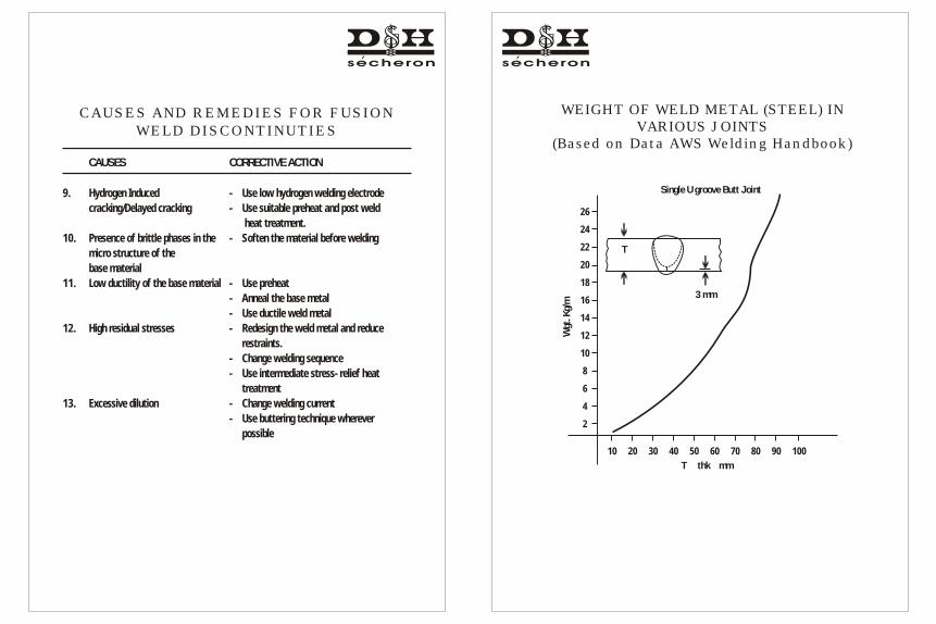
9. Hydrogen Induced - Use low hydrogen welding electrode
cracking/Delayed cracking - Use suitable preheat and post weld
heat treatment.
10. Presence of brittle phases in the - Soften the material before welding
micro structure of the
base material
11. Low ductility of the base material - Use preheat
- Anneal the base metal
- Use ductile weld metal
12. High residual stresses - Redesign the weld metal and reduce
restraints.
- Change welding sequence
- Use intermediate stress- relief heat
treatment
13. Excessive dilution - Change welding current
- Use buttering technique wherever
possible
WEIGHT OF WELD METAL (STEEL) IN VARIOUS JOINTS
(Based on Data AWS Welding Handbook)
Single U groove Butt Joint
26
24
22
20
18
16
14
12
10
8
6
4
2
Wgt
. Kg/
m
T thk mm
10 20 30 40 50 60 70 80 90 100
3 mm
T

WEIGHT OF WELD METAL (STEEL)IN VARIOUS JOINTS
(Based on Data AWS Welding Handbook)
Double V groove joint
17
16
15
14
13
12
11
10
9
8
7
6
5
4
3
2
1
Wgt
. Kg/
m
T thk mm
5 10 15 20 25 30 35 40 45 50 55 60 65 70 75
060
3mm
WEIGHT OF WELD METAL (STEEL) IN VARIOUS JOINTS
(Based on Data AWS Welding Handbook)
Single V groove Butt joint
4.75
4.35
3.95
3.55
3.15
2.75
2.35
1.95
1.55
1.15
0.75
0.35
Wgt
. Kg/
m
T thk mm
2 4 6 8 10 12 14 16 18 20 22 24 26
3 mm T>82 mm T>_ 8
T
060
S

WEIGHT OF WELD METAL (STEEL) IN VARIOUS JOINTS
(Based on Data AWS Welding Handbook)
Single bevel groove joint
2.50
2.30
2.10
1.90
1.70
1.50
1.30
110
0.90
0.70
0.50
0.30
0.10
Wgt
. Kg/
m
T thk mm
2 4 6 8 10 12 14 16 18 20 22 24 26
045
3mm
WEIGHT OF WELD METAL (STEEL) IN VARIOUS JOINTS
(Based on Data AWS Welding Handbook)
Fillet welds3.15
2.95
2.75
2.55
2.35
2.15
1.95
1.75
1.55
1.35
1.15
0.95
0.75
0.55
0.35
0.15
Wgt
. Kg/
m
Weld size mm T
2 4 6 8 10 12 14 16 18 20 22 24

USEFUL FORMULAE
1. Carbon Equivalent :
C : C + Mn/6 + (Cr + Mo +V)/5 + (Ni + Cu) /15E
2. % Delta Ferrite :
% F : 3[Cr - 0.93 Ni - 6.7]eq eq
3. Heat Input :
H (KJ/mm) : V x l x 60
V x 1000s
Where V = Voltage
I = Current
V = Welding speed in mm/min.s
4. Preheating
C = C + Mn + Ni + Cu + Cr + Mo + VC
6 15 5
C = C x 0.005 x tt C mm
C = C + CE C t
0Preheat temperature C : 350 C -0.25E
A-
NU
MB
ER
CL
AS
SIF
ICA
TIO
N O
F F
ER
RO
US W
EL
D M
ET
AL
AN
AL
YS
IS F
OR
PR
OC
ED
UR
E Q
UA
LIF
ICA
TIO
N
A N
o.T
ype
of w
eld
Dep
osit
W
eigh
t %
CC
rM
oN
iM
nS
i
1.
Mild
ste
el0
.15
--
-1
.60
1.0
0
2.
C-M
o0
.15
0.5
00
.40
/0.6
5-
1.6
01
.00
3.
Cr
(0.4
-2%
)-M
o0
.15
0.4
0/2
.00
0.4
0/0
.65
-1
.60
1.0
0
4.
Cr(
2%
-6%
)-M
o0
.15
2.0
0/6
.00
0.4
0/1
.5-
1.6
2.0
0
5.
Cr(
6%
-10
.5%
)-M
o0
.15
6/1
0.5
00
.40
/1.5
-1
.20
2.0
0
6.
Chr
ome-
Mar
tens
itic
0.1
51
1.0
0/1
5.0
00
.70
-2
.00
1.0
0
7.
Chr
ome-
Ferr
itic
0.1
51
1.0
0/3
0.0
01
.00
-1
.00
3.0
0
8.
Cr-
Ni
0.1
51
4.5
/30
.00
4.0
07
.5/1
5.0
02
.51
.00
9.
Cr-
Ni
0.3
02
5.0
0/3
0.0
04
.00
15
/37
.00
2.5
1.0
0
10
.N
icke
l (0
.8 t
o 4
%)
0.1
5-
0.5
50
.8/4
.00
1.7
1.0
0
11
.M
n-M
o0
.17
-0
.25
/0.7
50
.85
1.2
5/2
.25
1.0
0
12
.N
i-C
r-M
o0
.15
1.5
0.2
5/0
.81
.25
/2.8
1.7
5/2
.25
1.0
0
: S
ingl
e va
lues
sh
own
abov
e ar
e m
axim
um
.
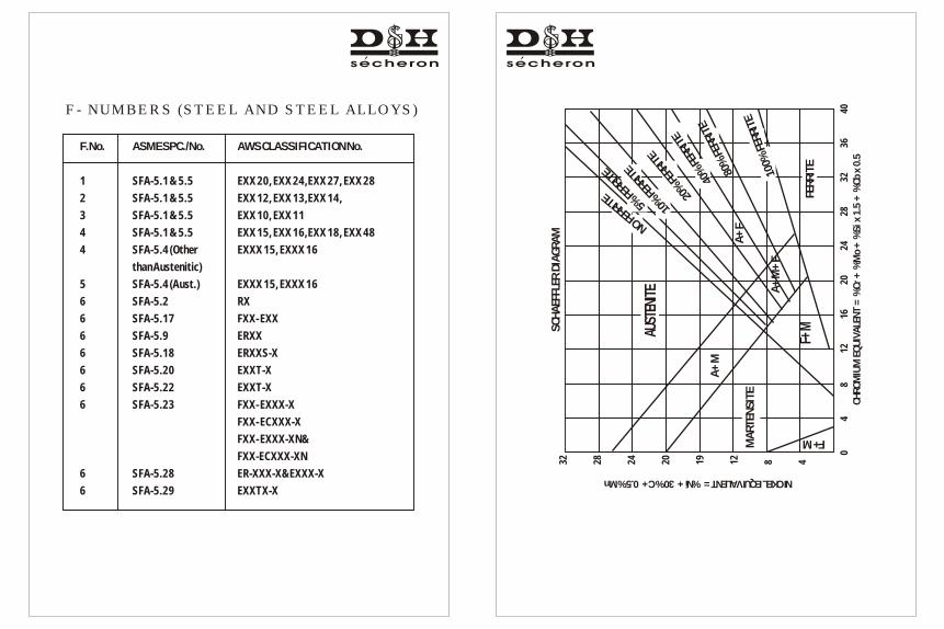
F- NUMBERS (STEEL AND STEEL ALLOYS)
F.No. ASME SPC./No. AWS CLASSIFICATION No.
1 SFA-5.1 & 5.5 EXX 20, EXX 24,EXX 27, EXX 28
2 SFA-5.1 & 5.5 EXX 12, EXX 13,EXX 14,
3 SFA-5.1 & 5.5 EXX 10, EXX 11
4 SFA-5.1 & 5.5 EXX 15, EXX 16,EXX 18, EXX 48
4 SFA-5.4 (Other EXXX 15, EXXX 16
than Austenitic)
5 SFA-5.4 (Aust.) EXXX 15, EXXX 16
6 SFA-5.2 RX
6 SFA-5.17 FXX- EXX
6 SFA-5.9 ERXX
6 SFA-5.18 ERXXS-X
6 SFA-5.20 EXXT-X
6 SFA-5.22 EXXT-X
6 SFA-5.23 FXX- EXXX-X
FXX- ECXXX-X
FXX- EXXX-XN&
FXX-ECXXX-XN
6 SFA-5.28 ER-XXX-X&EXXX-X
6 SFA-5.29 EXXTX-X
NICKEL EQUIVALENT = %Ni + 30% C + 0.5% Mn
A+
M
A+
F
F+M
F+M
SC
HA
EFFL
ER D
IAG
RA
M
CH
RO
MIU
M E
QU
IVA
LEN
T =
%C
r +
%M
o +
%S
i x 1
.5 +
%C
b x
0.5
32 28 24 20 19 12 8 4
0
4
8
12
1
6
20
2
4
28
3
2
36
4
0
AUST
ENIT
E
MA
RTE
NS
ITE
A+
M+
F
FER
RIT
E0%
1
0FE
RRIT
E
%80
FER
ITE
R0
T
4%
ER
RIE
F20
% F
RT
ERI
E
O FEN
RRITE
R
5 FE
RIT
%
E
10 FE
RTE
%R
I

18 16 14 12 10
18 16 14 12 10
18
20
2
2
24
26
28
3
0
18
20
2
2
24
26
28
3
0
A
AF FA
F
0
24
812
1620
2428
3545
55
65
75
85
95
610
1418
2226
0340
5060
0780
90
00 1
Ni = Ni + 35 C + 20 N + 0.25 Cu eq
Cr
= C
r +
Mo
+ 0
.7 N
beq
WR
C -
199
2 D
IAG
RA
M

SU
GG
ES
TE
D C
ON
SU
MA
BLE
S F
OR
VA
RIO
US
B
AS
E M
ET
AL C
OM
BIN
AT
ION
S
BA
SE
ME
TA
LS
C.
S.
C-M
o1
.25
Cr-
Mo
2 &
2.2
5 C
r-M
o3
& 5
Cr-
Mo
7 C
r-M
o9
Cr-
Mo
9 C
r-M
o-V
3X
X-S
S
C. S
teel
C-M
o
1.2
5 C
r-M
o
2 &
2.2
5 C
r-M
o
3 &
5 C
r-M
o
7 C
r-M
o
9 C
r-M
o
9 C
r-M
o-V
3XX-S
S
C. S
teel
C-M
o
1.2
5 C
r-M
o
2 &
2.2
5 C
r-M
o
3 &
5 C
r-M
o
7 C
r-M
o
9 C
r-M
o
9 C
r-M
o-V
3XX-S
S
A A A A A A A A IA A A A A A A A I
A B B B B B B B IA B B B B B B B I
A B C C C C C C IA B C C C C C C I
A B C D D D D D IA B C D D D D D I
A B C D E E E E IA B C D E E E E I
A B C D E F F F IA B C D E F F F I
A B C D E F G G IA B C D E F G G I
A B C D E F G H IA B C D E F G H I
I I I I I I I I -I I I I I I I I -
NO
TE
: P
lease
see t
he A
, B,
C,
D,
E,
F, G
, H
, &
I d
eta
ils
are
as
above.
NO
TE
: P
lease
see t
he A
, B,
C,
D,
E,
F, G
, H
, &
I d
eta
ils
are
as
above.
PR
OD
UC
T S
EL
EC
TIO
N C
HA
RT
A B C D E F G H I
Le
tte
rC
om
po
sit
ion
C-S
teel
C-M
o
1.2
5Cr-
Mo
2.2
5Cr-
Mo
5Cr-
Mo
7Cr-
Mo
9Cr-
Mo
9Cr-
Mo-V
Ni-Cr-
Fe
SM
AW
Bra
nd
Supra
therm
e/
Supra
therm
e (
Mod)
Moly
therm
e
Moly
therm
e (
Mod)
Cro
moth
erm
e-1
Cro
moth
erm
e-1
(M
od)
Cro
moth
erm
e-1
(Spl)
Cro
moth
erm
e-1
L
Cro
moth
erm
e-1
L (M
od)
Cro
moth
erm
e-2
Cro
moth
erm
e-2
(M
od)
Cro
moth
erm
e-2
(Spl)
Cro
moth
erm
e-2
L
Cro
moth
erm
e-2
L (M
od)
Cro
moth
erm
e-5
Cro
moth
erm
e-5
(M
od)
Cro
moth
erm
e-5
(Spl)
Cro
moth
erm
e-5
L
Cro
moth
erm
e-5
L (M
od)
Cro
moth
erm
e-7
AW
S C
lass
E7018
E7018-A
1
E8018-B
2
E7018-B
2L
E9018-B
3
E8018-B
3L
E8018-B
6 o
r
E502-1
5
E8018-B
6L
E8018-B
7 o
r
Bra
nd
Bra
nd
AW
S C
lass
AW
S C
lass
GT
AW
FC
AW
F 7
0S-2
Auto
therm
e C
-Mo
F C
-Mo
Auto
therm
e C
r-M
o 1
F C
r-M
o 1
Auto
therm
e C
r-M
o 2
F C
r-M
o 2
Auto
therm
e C
r-M
o 5
F C
r-M
o 5
- - F C
r-M
o 9
1
FW
NiC
r-3
FW
309
(For
non c
yclic
therm
al se
rvic
e)
ER70S-2
ER70S-A
1
ER80S-B
2
ER90S-B
3
ER80S-B
6 o
r
ER502
- - ER90S-B
9
ERN
iCr-
3
ER309
Maxf
il 31B
Maxf
il 70A1
Maxf
il 81R
Maxf
il 41R
Maxf
il 56
- - - -
E70T-5
E70T5-A
1
E81T1-B
2
E91T1-B
3
E80T5-B
6
- - - -
Cro
moth
erm
e-7
L
Cro
moth
erm
e-9
Cro
moth
erm
e-9
L
Cro
moth
erm
e-9
(M
od)
D&
H 1
200T
Cro
nitherm
e 2
5/1
2
D&
H 3
09M
o
(For
non c
yclic
therm
al
serv
ice)
E7Cr-
15
E8018-B
8 o
rE505-1
5E8018-B
8L
E9018-B
9
EN
iCrF
e-2
E309-1
6
E309M
o-1
6
E8018-B
7L

SU
MM
AR
Y O
F C
OR
RO
SIO
N T
ES
T A
S P
ER
AS
TM
A2
62
-02
a(I
nclu
din
g c
han
ges
made i
n t
he y
ear
20
04
-20
05
)
Pra
ctic
eA
BC
EF
Me
diu
mO
xalic
Aci
dF
err
ic S
ulp
ha
te S
ulp
hu
ric
65
% N
itric
Aci
d in
bo
ilin
g
Co
pp
er-
cop
pe
r S
ulp
ha
te
Co
pp
er-
cop
pe
r S
ulp
ha
te
Aci
d in
bo
ilin
g c
on
diti
on
con
diti
on
16
% s
ulfu
ric
Aci
d5
0%
Su
lfuric
Aci
d in
b
oili
ng
co
nd
itio
n
Du
ratio
nR
ap
id M
eth
od
1
20
Ho
urs
Te
st2
40
Ho
urs
Te
st1
5
Ho
urs
Te
st1
20
Ho
urs
Te
st
Eva
lua
tion
by
Etc
he
d s
urf
ace
is
exa
min
ed
We
igh
t lo
ss in
che
s p
er
mo
nth
We
igh
t lo
ss in
che
s p
er
mo
nth
Be
nd
te
st. T
he
te
st s
pe
cim
en
W
eig
ht lo
ss in
che
s p
er
on
me
tallu
rgic
al m
icro
sco
pe
2
87
X W
02
87
X W
sha
ll b
e b
en
t th
rou
gh
18
0
mo
nth
a
t 2
50
X to
50
0 X
. T
his
te
st is
=
---
----
----
----
= -
----
----
----
--a
nd
ove
r a
d
iam
ete
r e
qu
al to
2
87
X W
use
d fo
r a
cce
pta
nce
of
A
x t x
d A
x t x
dth
e th
ickn
ess
of th
e
spe
cim
en
= -
----
----
----
--m
ate
ria
l.b
ein
g b
en
t. T
he
be
nt sp
eci
me
n
A x
t x
dsh
all
be
exa
min
ed
un
de
r lo
w
(20
X)
ma
gn
ific
atio
n. T
he
a
pp
ea
ran
ce o
f fis
sure
s o
r cr
ack
s in
dic
ate
s th
e p
rese
nce
of
inte
r g
ran
ula
r a
tta
ck.
Su
ita
ble
fo
rA
ISI: 2
01
, 2
02
, 3
01
, 3
04
, D
ete
cts
De
tect
sD
ete
cts
De
tect
s3
04
L, 3
04
H, 3
16
, 3
16
L,
Inte
rgra
nu
lar
atta
ck a
sso
cia
ted
Ch
rom
ium
ca
rbid
e in
30
4,
Ch
rom
ium
ca
rbid
e in
20
1, 2
02
,C
hro
miu
m c
arb
ide
in3
16
H, 3
17
, 3
17
L, 3
21
, 3
47
with
ch
rom
ium
ca
rbid
e3
04
L, C
F-8
an
d c
hro
miu
m3
01
,
No
te: t =
tim
e o
r e
xpo
sure
ho
urs
.
2A
= A
rea
cm
W =
we
igh
t lo
ss in
'g'
3 d
= d
en
sity
g/c
m
3D
en
sity
fo
r C
r N
i ste
els
= 7
.9 g
/cm
3D
en
sity
fo
r C
r-N
i-M
o =
8 g
/cm

Name of Agency Brand Name
NPCIL Batox-B, Cromotherme-2, Cronitherme-25/12, D&H 309L, Exobel,
F 70S2, FW 308L, FW 309L, Medio, Molytherme, Rutox-A, Rutox-A(St),
Rutox-B, Rutox-D, Rutox-E, Rutox-Mo, Supratherme, Supratherme-Ni,
Supratherme(Spl)
RD & SO Cronitherme-25/12, Econotherme, Ferrovite, Indotherme, LoTherme-
210R, LoTherme-352(R), LoTherme-468(Spl), LoTherme-801R,
LoTherme-802R, Medio, Medio-R, Molytherme-R, Norma, Rapidex,
Rutox-A, Supratherme, Supratherme-R, Unitherme
BIS Econotherme, Exobel, Indotherme, Medio, Medio-V, Norma, Norma-V, P-4,
Popular, Supratherme
CIB-MP Autotherme-1, Cromotherme-1, Cromotherme-2, Cromotherme-9,
Cromotherme-9(Mod), Exobel, Indotherme, Medio, Medio-Cr-/Mo,
Medio-2Cr-/Mo, Molytherme, Molytherme(Extra), Norma, Supratherme,
Supratherme-Ni(Spl), Supratherme(Spl), Tensal
IRS Exobel, Medio, Supratherme
ABS Indotherme, Medio, Norma, Supratherme, Supratherme (Spl)
DNV Exobel, Indotherme, Medio, Norma, Supratherme
BV Cellutherme, F 70 S2, Indotherme, Medio, Norma, P-4,Supratherme,
Supratherme (Spl) H4R
BRAND APPROVAL FROM VARIOUS AGENCIES
LRS Exobel, Indotherme, Medio, Medio-S, Norma, P-4, Rapidex, Supratherme
EIL Cellutherme, Cromotherme-1, Cromotherme-1L,Cromotherme-2,
Cromotherme-5, Cronitherme-25/12, D&H 309L, D&H 309Mo,
Indotherme, Medio, Molytherme, Norma, Rutox-A, Rutox-A(St), Rutox-B,
Rutox-D, Rutox-E, Rutox-Mo, Rutox-Mo(St), Supratherme,
Supratherme-Mod, Supratherme (Spl), Supratherme-Ni (Spl),
PDIL Batox-F(U), Batox-F(U)M, Cellutherme, Cromotherme-1, Cromotherme-2,
Cronitherme-25/12, D&H 150L, D&H 309Mo, D&H 310-16, D&H 1200T,
D&H 1212, F 70S-2, Indotherme, Medio, Molytherme, Norma, Rutox-A,
Rutox-A(St), Rutox-B, Rutox-C, Rutox-D, Rutox-F, Rutox-Mo,
Supratherme, Supratherme-Ni (Spl), Supratherme (Spl),
Toyo Cellutherme, Cromotherme-1, Cromotherme-2, Cronitherme-25/12,
D&H 309L, D&H 1212, Exobel, FW308, FW308L, FW309, FW309L,
FW316, FW347, Medio, Medio-S, Molytherme, Norma, Rutox-A,
Rutox-A(St), Rutox-B, Rutox-D, Rutox-Mo, Supratherme,
Supratherme-Ni, Supratherme(Spl)
CIM - Ichapur Rutox-Mo, Rutox-Mo(St), Ultratherme
MDL Corotherme (Spl)
Stamicarbon & Batox-F(U)M
Snamprogetti