filling the model die casting mould – analysis …imim.pl/files/archiwum/vol3_2010/19.pdf · 781...
TRANSCRIPT
A R C H I V E S O F M E T A L L U R G Y A N D M A T E R I A L S
Volume 55 2010 Issue 3
J. DAŃKO∗ R. DAŃKO∗, J. STOJEK∗∗, M. GÓRNY∗
FILLING THE MODEL DIE CASTING MOULD – ANALYSIS BY MEANS OF THE LEICA QWIN 2.2 PROGRAM
ANALIZA ZAPEŁNIENIA MODELOWEJ FORMY CIŚNIENIOWEJ ZA POMOCĄ PROGRAMU LEICA QWIN 2.2
The problem of broadly understood model investigations of the die casting process is one of the current researchsubjects undertaken by the Faculty of Foundry Engineering together with the Department of Process Automation ofthe Faculty of Mechanical Engineering and Robotics of AGH, University of Science and Technology. The undertakenresearch is aimed on elaboration of mathematical model of die cavity filling process in accordance with geometricfeatures of modelled casting, and its gating system able to reduce the molten metal stream dispersion degree in coldchamber die-casting machine.
The LEICA QWIN V. 2.2. program for the automatic image analysis was applied for measuring the area taken upby liquid during filling the flat mould in the model system of die casting cold-box machine. Utilizing the recording,obtained by means of filming the model moulds filling, which enabled the analysis of the mould cavity filling degree,realised at various injection velocities the suitability of the LEICA QWin v. 2.2. program for the automatic imageanalysis (for the rectangular model mould, gate hole 4.7 x 48 mm, two venting modes and two viscosities of modelliquid) was verified.
Keywords: die casting, mould filling, model investigations, LEICA QWin v. 2.2 Program
Zagadnienie szeroko rozumianych badań modelowych procesu odlewania ciśnieniowego jest jednym z aktualnych,tematów badawczych prowadzonych na Wydziale Odlewnictwa wspólnie z Katedrą Automatyzacji Procesów na WydzialeInżynierii mechanicznej i Robotyki Akademii Górniczo-Hutniczej w Krakowie. Realizowany wspólnie program badańmodelowych, ma na celu opracowanie opisu matematycznego procesu zapełniania wnęki formy ciśnieniowej adekwat-nego do geometrycznej charakterystyki modelowanego odlewu oraz jego systemu zasilania, zdolnego do ograniczeniazjawiska rozpraszania dyspersyjnego strugi metalu w zimnokomorowych maszynach ciśnieniowych.
Program LEICA QWIN V. 2.2. do automatycznej analizy obrazu zastosowano do pomiarów powierzchni zajętejprzez ciecz w trakcie zapełniania płaskiej formy w modelowym układzie maszyny ciśnieniowej zimnokomorowej.Wykorzystując rejestrację procesu zapełniania badanych form modelowych za pomocą filmowania, która umożliwiłaanalizę stopnia zapełnienia wnęki formy, realizowanego przy różnych prędkościach wtrysku sprawdzono przydatnośćprogramu LEICA QWin v. 2.2. do automatycznej analizy obrazu dla prostopadłościennej formy modelowej, dla szczelinywlewowej 4,7 x 48 mm, dwóch sposobów odpowietrzenia i dwóch lepkości cieczy modelowej.
1. Experimental stand
The experimental stand for model testing of thedie casting process and the physical model of thepressing system were presented in papers [3, 5]. Thefollowing systems are included in the experimentalstand:• Physical model of a die mould,• Physical model of a shot sleeve,• Electro-hydraulic steering system,• Hydraulic feeder.
In model investigations presented in reference[1] the physical model of the die mould with a
rectangular cavity of external dimensions: 280 mm(height) x 190 mm (width) x 10 mm (depth) wasused. Moulds models of 3 versions of the mouldcavity were made:• Rectangular cavity- version I,• Rectangular cavity with 2 circular inner elements
– version II,• Rectangular cavity with 2 inner elements of a
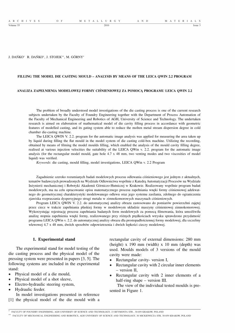
half-ring shape – version III.The view of the individual tested moulds is pre-
sented in Figure 1.
∗ FACULTY OF FOUNDRY ENGINERING, AGH UNIVERSIY OF SCIENCE AND TECHNOLOGY, 23 REYMONTA STR , 30-059 KRAKOW, POLAND∗∗ FACULTY OF MECHANICAL ENGINEERING AND ROBOTICS, AGH UNIVERSIY OF SCIENCE AND TECHNOLOGY, 30 MICKIEWICZA STR, 30-059 KRAKOW, POLAND

780
Fig. 1. Fig. 1. View of tested experimental moulds; a) Mould version I, external dimensions of mould cavity: 280×190×10 mm, mouldvolume Vf = 0.532 dm3, b) Mould version II, mould volume Vf = 0.441 dm3, c) Mould version III, mould volume, Vf=0.456 dm3
Each mould version had venting openings on theupper surface. The following markings were used forventing modes in the presented tests:O-O-O – full venting – total surface of ventingopenings 52 mm2, venting degree 2.73%,Z-O-Z – reduced venting – total surface of ventingopenings 8 mm2, venting degree 0.47%.
2. Measuring method
Two Newtonian fluids of a different viscosityand density obtained by the appropriate dilution ofglycerine by distilled water were used as model liq-uids. The presented investigations were performedfor the model liquid of a kinematic viscosity equal1.39·10−6 m2/s (1.39 cSt) – marked: “LIQUID 7%”,which approximately corresponds to the viscosity ofaluminium alloys at die casting. The second liquidhad viscosity 9.46·10−6 m2/s (9.46 cSt) – marked:“LIQUID 80%”, can represent viscosity similar tothe one of other aluminium alloys at casting in astate of partial crystallisation known as SSM (SemiSolid Metal).
The method of digital recording with a rate of30 frames per second was applied for the recordingof flow effects occurring during a mould filling [1].
Transparent elements of instrumentation appliedin tests and liquids allowed for the observation andrecording of flow effects, which created a new as-sessment possibility of a flow character, indepen-
dent of the Reynolds number. Applying, describedin papers [2, 3], the recording of the model mouldsfilling by means of filming, the analysis of the fillingdegree of the mould cavity as a function of time atvarious liquid injection velocities, was performed.The filling degree of the mould cavity was also per-formed – in analogical conditions – by measuringthe occupied surface by means of the LEICA QWinv. 2.2. program for the automatic image analysis [1,7].
3. The obtained results
The presented investigations were performed forthe model mould, version I – III, for the filling hole4.7×48 mm, two modes of ventilation and two vis-cosities of the model liquid. The example of a singleframes of the filling process filming for model liquidmarked “LIQUID 7%” and venting mode O-O-O isshown in Fig. 2, while in Fig. 3 the result of its planemap obtained by the LEICA QWin v. 2.2 program.
Analogous situation is shown in Fig. 4 and 5,where a three single frames of the filling processfilming for model liquid marked “LIQUID 80%” andventing mode Z-O-Z are combined with the resultsof their plane map obtained by the LEICA QWin v.2.2 program.
The results of surface area measurements madeby the LEICA QWin v. 2.2 microscope are presentedin Figs. 6-8.
Fig. 2. Single frames of the filling process filming. Version I, model liquid: “LIQUID 7%”, filling time: a) τ = 0,26(6) s,b) τ = 0,66(6) s, c) τ = 1,0 s; plunger velocity vp = 0.08 [m/s]; full venting mode O-O-O (52 mm2, venting degree 2.73%). Moulddrawing turned 90 degrees to the left in relation to the actual working position [1]

781
Fig. 3. Plane map of the single frames picture from Fig. 2, after the image analysis made by LEICA Qwin v. 2.2.program
Fig. 4. Single frames of the filling process filming. Version I, model liquid: “LIQUID 80%”, filling time: a) τ = 0,26(6) s,b)τ = 0,66(6) s, c)τ = 1,0 s; plunger velocity vp = 0.08 [m/s]; Z-O-Z – reduced venting mode (surface of venting openings 8 mm2,venting degree 0.47%). Mould drawing turned 90 degrees to the left in relation to the actual working position [1]
Fig. 5. Plane map of the single frame pictures from Fig. 4, after the image analysis made by LEICA Qwin v. 2.2.program
Fig. 6. Surface areas taken up by “LIQUID 80%”vs. filling time, calculated by means of the LEICA QWin v. 2.2 program, version Iof the mould [1, 7]

782
The analysis of data indicates a much more in-tensive evolution of a stream surface in the case ofusing the model liquid: “LIQUID 7%” of a lowerviscosity as compared with: “LIQUID 80%”. Thisindirectly points out a higher mobility and an in-clination for turbulences of the liquid of a lowerviscosity.
The cavity filling process of the moulg versionI at total venting (O-O-O) and at reduced vent-ing (Z-O-Z) are marked in Fig. 6 for version I ofthe mould and “LIQUID 80%”. Analogous data formodel liquid “LIQUID 7%” are given in Fig. 7.
A more significant influence of venting on thecavity filling degree by the model liquid of a lowerviscosity can be observed.
Fig. 7. Surface areas taken up by “LIQUID 7%” vs. filling time, calculated by means of the LEICA QWin v. 2.2 program, version Iof the mould [1]
Fig. 8. Surface areas taken up by “LIQUID 80%” vs. filling time, calculated by means of the LEICA QWin v. 2.2 program, versionIII of the mould, venting mode O-O-O

783
4. Analysis and interpretation of the obtainedresults
It can be pointed out that the ratio of the in-stantaneous liquid volume V(τ) to the total cavityvolume Vtotal fulfils the condition:
V(τ)
Vtotal=
F(τ) · g(τ)
Ftotal · g =Qact(τ) · τ(τ)
Qact · τz(1)
where:F(t) and Ftotal – surface of the mould cavity taken
up by liquid metal (calculated by the LEICA QWinv. 2.2 program) and the total observed surface [m2]– respectively,
Qact(t) and Qact – actual volumetric rate of fillinginstantaneous and average [m3/s] – respectively,
k = g(t)/g – quotient of the actual thickness ofthe liquid layer g(t) and the depth (thickness) of themould cavity (g) – which means the filling degreeof the mould cavity cross-section,
τ(τ) and τz – current and the total filling timedetermined by filming [s].
It can be assumed, that for the given conditionsof the mould filling, its instantaneous (Qact(t)) andaverage value (Qact) are equal to each other, and Eq.(1) can be presented in the form allowing to combinethe interesting quantities:
F(τ)
Ftotal· k =
τ(τ)
τz(2)
Quotient k is determined by:
k = 1 − ε =τ(τ)
τz· Ftotal
F(τ)(3)
The velocity of the model liquid (υcwlew) at the cavitygate was determined from the equation:
vtotal = vp · Fsleeve
Fgate; m/s (4)
where: Fsleeve, Fgate – surface of the shot sleeveand the mould filling gate [m2] – respectively, υp –average velocity of a plunger, [m/s].
The actual volumetric rate of filling, determinedon the basis of the cavity filling times by liquids ofthe determined viscosity is listed in Table 2.
The relation between the instantaneous apparentdensity of the mixture liquid – air, physical densityof the liquid phase and porosity of the mixture aregiven by the following equations:
ρ(τ) = ρ f · (1 − ε) = ρ f · k = ρ f ·τ(τ)
τz· Ftotal
F(τ)(5)
ε = 1 − k = 1 − τ(τ)
τz· Ftotal
F(τ)(6)
The expression ’a dispersion of a model liquidstream’ occurs in problems concerning filling of themould cavity at die casting. According to the def-inition the value of this expression is the ratio ofthe surface of the liquid to its volume. It can beassumed, in simplification, that in a flat system – inpractice two dimensional – the measure of the ex-pansion surface is the ratio of the scanned liquid sur-face (F(t)) to the observed surface Fcałk (240×190×10mm), in a similar fashion as given in Equation (2).Denoting by DD – dispersion degree of the liquidstream in the mould cavity, by F(t) – surface deter-mined by means of the LEICA QWin v. 2.2 program,by V(τ) instantaneous, geometric volume of the liq-uid, and by Vact – its actual volume, the equationfor the dispersion degree can be written as:
DD =F(t)
Vact(t)=
F(t)
V(t) · (1 − ε) =F(t)
F(t) · (1 − ε) · g =1
k · g ;
[1/cm](7)
or – when taking into account equations (3), (5) and(6)
DD =F(t)
Vact(t)=
1k · (1 − ε) =
ρ f
ρ(t) · k ; [1/cm] (8)
The calculation performed, as an example, fordata contained in Table 1 indicates, that in the rangeof obtained values for k = 0.44 – 1.0 value of DD =2.27 – 1.0 [1/cm], which means that only at the verybeginning of filling (when there is a full swellingof a liquid in the shot sleeve) and when liquid isfully forced through to venting channels its densi-ty is equal or nearly equal the nominal values. Inthe remaining time we are dealing with a mixtureof phases: model liquid – air of a dispersion de-gree higher than unity, characterising the presenceof dispersed gas bubbles.
The fragment of calculations of factors k, ρ(t)εfor data obtained from the process film analysis andby means of the LEICA QWin v. 2.2 program ispresented in Table 1.
5. Conclusions
An assessment of suitability of the LEICAQWin v. 2.2. program for automatic image analysis
in investigations of flow effects requires taking intoaccount the fact that the degree of covering a flatsurface of mould cavity by liquid – recorded by thismethod – does not inform about the thickness of this

784
TABLE 1The values of factors k, ρ(t),ε determined on the basis of the surface area measurement using the LEICA QWin v. 2.2 program
and the actual volumetric rate of filling by the model liquid – determined by filming. Filling gate 4.7×48 mm, venting areaFvent = 52 mm2 for venting mode O - O - O and Fvent = 8 mm2 for reduced venting mode Z -O -Z
ParametersSurface area taken up by model liquid [%] determined
by using LeicaQWin v. 2.2 program
Model mould Version I of the model mould
Filling time [s]: 0,26(6) 1,00 2,083
Value of tested factor k ρ(t) ε k ρ(t) ε k ρ(t) ε
vp =0.08 [m/s];venting mode O-O-O;“LIQUID 7%”
0.66 0.77 0.77 0.77 0.79 0.22 1.00 1,01 0.00
vp=0,163 [m/s];venting mode O-O-O;“LIQUID 7%”
0.47 0.54 0.54 0.54 0.55 0.46 1.00 1,01 0.00
vp=0,08 [m/s];venting mode O-O-O;“LIQUID 80%”
0.53 0.68 0.68 0.68 0.83 0.32 1.00 1,21 0.00
vp=0,163 [m/s];venting mode O-O-O;“LIQUID 80%”
0.49 0.63 0.63 0.63 0.76 0.37 1.00 1,209 0.00
vp=0,08 [m/s];venting mode Z-O-Z;“LIQUID 7%”
0.85 0.83 0.83 0.83 0.84 0.17 1.00 1,015 0.00
vp=0,163 [m/s];venting mode Z-O-Z;“LIQUID 7%”
– 0.58 0.58 0.58 0.58 0.42 1.00 1,01 0.00
vp=0,08 [m/s];venting mode Z-O-Z;“LIQUID 80%”
0.62 0.77 0.77 0.77 0.93 0.23 1.00 1,21 0.00
vp=0,163 [m/s];venting mode Z-O-Z;“LIQUID 80%”
0.45 0.59 0.59 0.59 0.72 0.41 1.00 1,21 0.00
TABLE 2The list of empiric formulas for the determination of the actual volumetric rate of model liquid during filling
– mould versions I-III – experiment concerns different model liquids, venting modes and velocities in filling gate.Shot sleeve filling degree 50% (ϕ = 0.5)
Actual average volumetric rate of filling determined by filming Qfilm [cm3/s].
Average volumetric rate of filling by model liquid “LIQUID 80%”Venting mode O-O-O;4.7×48 mm Qact = −23, 732 v2
total + 239,12 vtotal; R2 = 0,99
Venting mode O-O-O;3,0×48 mm Qact = −12,748 v2
total + 163,24 vtotal; R2 = 0,99
Venting mode Z-O-Z;4,7×48 mm Qact = −23,121 v2
total + 221,7 vtotal; R2 = 0,99
Venting mode Z-O-Z;3,0×48 mm Qact = −10,112 v2
total + 131,7 vtotal; R2 = 0,98
Average volumetric range of filling by model liquid “LIQUID 7%”Venting mode O-O-O;4,7×48 mm Qact = −18,48 v2
total + 181,21 vtotal; R2 = 0,99
Venting mode O-O-O;3,0×48 mm Qact = −12,697v2
total + 153,83 vtotal; R2 = 0,99
Venting mode Z-O-Z;4,7×48 mm Qact = −20,198 v2
total + 178,99 vtotal; R2 = 0,98
Venting mode Z-O-Z;3,0×48 mm Qact = −9,15 v2
total + 117,27 vtotal; R2 = 0,99

785
liquid layer (under the given area), what is essen-tial for the determination of the actual volumetric,or mass, rate of filling. In the case of thin-walledmoulds, fulfilling in practice the two-dimensionalcondition, the applicability of the method is doubt-less.
The condition for the proper using of thismethod is the simultaneous application of the film-ing method for the time of the filling process deter-mination. This allows to determine not only the areabut also the volumetric concentration of the modelliquid stream being introduced into the mould, thusenabling the determination of instantaneous densityof the two-phase mixture liquid-air (ρ(τ)), its porosity(ε(τ)) and dispersion degree DD.
As results from the given data, the thicknessof the filmed stream calculated on the basis of thesurface scanned by the LEICA QWin v. 2.2. pro-gram and reduced to the initial liquid density is ofa lower value than the mould cavity depth. At theprocess end the calculated liquid density increasesto the nominal value.
Acknowledgements
The authors acknowledge The Polish Ministry of Scienceand Higher Education for financed support under Project No3TO 8B 025 28 (Project AGH No. 18.25.170.266)
REFERENCES
[1] J. D a ń k o, et. al: “Model testing of hydrodynamicproperties of metal stream and mould filling in cold– chamber die casting machines. Research ProjectNo 3TO 8B 025 28 finansed by Polish Ministry ofScience and Higher Education in years 2005-2007.
[2] J. D a ń k o, J. S t o j e k, R. D a ń k o, Model test-ing of II phase of die casting process At central po-sitioning of running gate. Proceedings of the XXXIScientific Conference, Foundry Engineering Facul-ty, 2007, Kraków, pp. 161-168 (in Polish).
[3] J. D a ń k o, J. S t o j e k, R. D a ń k o, Modeltesting of casting process in cold-chamber die cast-ing machine. Archives of Metallurgy and Materials,vol. 52, is.3, pp. 503-513 (2007).
[4] I. W. G a r b e r, Theoretical analysis and experi-mental observation of air entrapment during coldchamber filling. Die Casting Engineer, May-June1982, pp. 161-22.
[5] J. D a ń k o, R. D a ń k o, J. S t o j e k, Cognis-able effect of model investigations of die castingprocesses. Foundry Engineering – Quarterly of Pol-ish Academy of Sciences, The Katowice Branch,Commission of Foundry Engineering, vol. 8, spe-cial issue 1, ISNN (1897-3310), p. 57-62 (2008).
[6] J. D a ń k o, R. D a ń k o, J. L e l i t o, Modellingof flow phenomena in the process of filling the diemould – an application of the Nova Flow Program.Foundry Engineering – Quarterly of Polish Acad-emy of Sciences, The Katowice Branch, Commis-sion of Foundry Engineering, vol. 8, special issue4, ISNN (1897-3310), p. 31-36 (2008).
[7] J. D a ń k o, Z. J ę d r z y k i e w i c z, The testingstand for investigation of flow phenomena occur-ring during filling the die cavity by means of coldchamber die-casting machine. Archives of Foundry, vol. 52, issue 3, pp. 301-306 (2006).
[8] J. D a ń k o, R. D a ń k o, M. G ó r n y, The LE-ICA QWin v. 22 program for automatic Pictureanalysis applied for measurement the surface tak-en by liquid during the filling of the model mouldin cold chamber die casting machine. ArchiwumTechnologii Maszyn i Automatyzacji. Poznań, Vol.28 nr 3, s.15-24 (2008) (in Polish).
[9] J.-Ch. L e e, H.-K. S e o k, H.-I. L e e, Influenceof the gating geometry and the injection rate onthe flow character of the aluminium alloy A356in the state of its partial crystallization. PrzeglądOdlewnictwa nr 2 (2004).
[10] L. F r o m m e r, Handbuch der Spritzgusstechnik.Julius Springer, Berlin 1933.
[11] W. K o s t e r, K. G o h r i n g, Uber den Einstromund Fullvorgang. Giesserei 1941, H2, Nr 26.
[12] H. K. B a r t o n, The Injection of Metal intoDiecastings. Machinery, 1944, serie L., vol. 64, nr1642, vol. 65, nr 1664.
Received: 10 February 2010.