film coextrusion - lyondellbasell industries | lyondellbasell · pdf file ·...
TRANSCRIPT

lyb.com
Film Coextrusion A Troubleshooting Guide

Film Coextrusion:A Troubleshooting Guide
Successful production of coextruded products depends on several key factors, including polymer selections, hardware design (screw, feedblock/die, handling equipment, layer construction and optimal processing conditions). Proper selection and adjustment of each factor will minimize difficulties and ensure high quality coextrusion results.
Troubleshooting methods for coextrusion become increasingly complex as the number of layers in the structure increases, as the asymmetry of multi-layer construction grows, or as processing and rheological characteristics of coextruded materials differ greatly from one another. Understanding the problems associated with non-uniform layer distribution and interfacial instability between layers or on film surfaces is very important when troubleshooting the coextrusion process.
1
(This article originally appeared in Converting Magazine, November 1994.)

The Uniformity Problem
Non-uniform layer distribution is one of the more common problems encountered in film coextrusion. This non-uniformity may appear in either the direction of extrusion or tangential to the direction of film production.
2
Layer uniformity in the machine direction can be influenced by die imperfections, poor die design or adjustment, excessive extruder pressure variation, variable film tension, or film bubble or web instability.
Layer uniformity tangential to machine direction can be influenced by poor melt temperature uniformity, viscosity mismatch between layers, poor hardware design, or viscoelastic flow characteristics induced by excessive shear stress.
Poor layer uniformity tangential to machine direction is caused by non-uniform melt temperature across a melt pipe, feedblock and/or die, as well as poor melting in an extruder. Melt temperature variance alters viscosity uniformity, which exhibits a change in flow characteristics and layer distribution. Melt temperature of a single polymer stream can often vary by as much as 30°F. A general rule of thumb is
to achieve ±2°F or less variation in melt temperature for each extruder.
Homogeneous melt temperatures can be achieved through installation of a static mixer in the melt pipe, a dynamic mixer on the extrusion screw or a more efficient screw design, or through adjustment of pipe, feedblock and/or die temperatures.
Variation in the thickness of a film, which eventually reaches a steady-state condition of non-uniformity (assuming homogeneous melt temperature conditions for each polymer), can be caused by a viscosity mismatch between layers. In a coextrusion system, lower-viscosity polymers migrate to the region of highest shear stress (nearest the die wall) and tend to encapsulate higher-viscosity polymers. The amount of migration is dependent on the degree of viscosity mismatch, the length of the flow path, and the shear stress in the system.

Improving Layer Variation
Improvements in layer variations that are caused by viscosity-induced flow behavior can be achieved through adjustment of melt temperature, modification of distribution channels in the feedblock or die, or selection of a polymer with different viscosity characteristics which most commonly are measured by melt index. Also, annular dies typically are more tolerant of viscosity mismatch than flat-die systems.
3
Non-uniform layer distribution in the direction tangential to extrusion can also be caused by poor hardware design. Improperly designed flow channels of the feedblock or die can cause poor steady-state layer distribution of materials, even with the most closely matched viscosities.
Non-uniform distribution of layers, in the form of parabolic flow lines, intermixing of layers, roughness between polymer boundaries, melt fracture, or uncharacteristically high haze, can be caused by interfacial instability between layers or on film surfaces. The instabilities are believed to be a result of the viscoelastic behavior of polymers at the die land or region of highest shear stress.
Improvements in layer instabilities can be achieved by reducing the shear stress between coextrusion layers and/or the
die-land surfaces. Shear stress can be reduced by decreasing total output rate, increasing skin-layer melt temperature (decrease in viscosity), increasing the die gap, adding a process lubricant to the skin material, or selecting a lower viscosity material.
An increase in the thickness of the skin layer can also reduce instability between polymer layers by moving the interface further from the high-shear-stress die wall. This is especially significant for asymmetric coextrusion constructions.
Finally, if coextrusion layers exhibit dramatic differences in melt elasticity, then choose materials that match more closely in extrudate elasticity as measured by extrudate swell.

Troubleshooting At A Glance
4
Problem Possible Cause Solution
Lines in the film surface Die imperfections
• Clean die buildup
• Remove contaminants from polymer melt channel
• Repair die nicks and burrs
Gauge bands on film roll
Poor die design
• Install spiral-channel die design to eliminate weld lines
• Install rotating nip assembly in tower
Poor die adjustment• Adjust concentricity of die gap
• Center air ring in relation to die gap
Repeating pattern of variation in thickness of layer(s)
Excessive extruder pressure variation (surging)
• Achieve ±1 percent or less variation in total head pressure for each extruder
• Adjust extruder temperature profile (feed and transition zones)
• Increase back pressure with restrictor flow plug
• Increase back pressure by installing fine-mesh screen pack
• Change screw design of surging extruder(s)
• Check for worn screw(s) and replace if needed
• Check extruder feedthroat(s) for bridging and correct if needed
Variable film tension • Eliminate variability in drive speed
Film bubble instability
• Protect bubble from atmospheric air turbulence
• Correct pressure instability of air ring and/or internal air flow

5
Problem Possible Cause Solution
Intermittent and somewhat random variation in thickness of layer(s)
Poor melt temperature uniformity
• Achieve ±2°F or less variation in melt temperature for each extruder
• Adjust extruder temperature profile to ensure complete melting of extrudate
• Install new screw design with dynamic mixer for more efficient melting capacity
• Reduce screw speed for increased residence time to complete melting of the polymer(s)
• Adjust temperature of feed channels, die and/or feedblock
Variation in thickness of layer(s) that reaches steady-state distribution
Viscosity mismatch of polymer layers
• Select polymers with matching viscosities
• Adjust temperature of polymers to aid in matching viscosities
Poor hardware design • Change die and/or feedblock design
Uncharacteristically high film hazeViscoelastic flow characteristics induced by excessive shear stress between layers and/or feedblock/die surfaces
• Select lower-viscosity skin layer(s)
• Increase melt temperature of skin-layer polymers
• Increase die temperatures
• Reduce total extrusion output
• Increase die-gap opening
• Add process lubricant to skin-layer polymer
• Increase thickness of skin layers
• Select polymer(s) that exhibit similar melt elasticity behavior (extrudate swell)
Parabolic-shaped flow lines in direction of extrusion
Same as for uncharacteristically high, film-haze problem
• Same as for uncharacteristically high, film-haze problem
Intermixing of polymer layersSame as for uncharacteristically high, film-haze problem
• Same as for uncharacteristically high, film-haze problem
Roughness between polymer-layer boundaries
Same as for uncharacteristically high, film-haze problem
• Same as for uncharacteristically high, film-haze problem
Melt fracture of film surfaceSame as for uncharacteristically high, film-haze problem
• Same as for uncharacteristically high, film-haze problem

Coextrusion Processing Defined
Successful Production of Coextruded Products Depends on Three Key Factors
The conversion of multiple thermoplastics, flowing through separate streams, that are combined into a common primary passage and then shaped by a die. Multiple layers provide properties that cannot be provided by a single material for high barrier coextrusion processing. The main classes are: film; sheet; tubing; coating; and blowmolded shapes.
1. Polymer Selections
2. Design of Hardware Screws, Feedblock/Die, Handling
3. Coextrusion Layer Construction
4. Optimal Processing Conditions
6

Layer Uniformity is Influenced by:
Interfacial Flow Instabilityis Caused by:
• Variations in extrusion pressure
• Nominal extrusion melt temperature
• Viscosity-induced web flow
• Bubble or melt instability
• Variable film tension
• Poor die design or improper adjustment
• Die imperfections or contaminants
• Interfacial critical shear stress
7

Extrusion Pressure Variations
Variation in extrusion pressure, often referred to as surging, is directly related to feeding stability of an extruder.
Improving layer uniformity caused by pressure variation can be achieved through:
• Adjustment of back pressure
– Screen pack
– Restrictor flow plug
• Extrusion screw design of feed and transition sections
• Adjustment of extrusion screw-temperature profile
• Prevent polymer bridging in feed throat
• Replace/repair worn extrusion screw
8

Head Pressure Trace
Layer Thickness Instability Caused by Pressure Variation
9
Stable Flow Uniform thickness
Onset of Instability Small gauge variation
Severe Instability Large gauge variation
FLOWDIRECTION
FLOWDIRECTION
FLOWDIRECTION

Extrusion Flange Back Pressure Adjustment
Typical Arrangement of Coarse and Fine Screens Between the Screw and Breaker Plate
10

Melt Temperature Variations
Melt Thermocouple Trace
Non-uniform melt temperature across a melt pipe, as well as poor polymer melting in an extruder, cause poor layer uniformity.
11
Homogeneous polymer melt temperatures can be achieved through:
• Static and/or dynamic mixers
• Adjustment of pipe and die temperatures
• Adjustment of extrusion screw temperature profile
• Replace/repair worn extrusion screw

Typical Temperature Profile of Polymer Melt Stream in Pipe
Layer Thickness Instability Caused by Non-uniform Melt Temperature
Stable Flow Uniform thickness
Onset of Instability Small gauge variation
Severe Instability Large gauge variation
12
BARREL WALL
0 1/8 1/4 3/8 1/2 5/8 3/4 7/8 0
ºF
BARREL CENTER LINE
BARREL WALL
414º
410º
406º
402º
398º
394º
390º
386º
382º
378º
374º
FLOWDIRECTION
FLOWDIRECTION
FLOWDIRECTION

Adjustable Depth Probe Melt Thermocouple
Distributive Mixing Sections
Dulmadge mixing section (Dow)
Pineapple mixing section
Saxton mixing section (DuPont)
Cavity-transfer mixing section (Davis-Standard)
Pin mixing section (Barmag)
Slotted-screw flight (Axon)
Two types of static mixers (Kenics and Ross ISG)
13
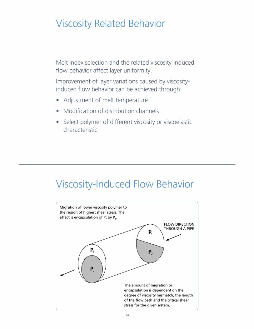
Viscosity Related Behavior
Viscosity-Induced Flow Behavior
Melt index selection and the related viscosity-induced flow behavior affect layer uniformity.
Improvement of layer variations caused by viscosity-induced flow behavior can be achieved through:
• Adjustment of melt temperature
• Modification of distribution channels
• Select polymer of different viscosity or viscoelastic characteristic
Migration of lower viscosity polymer to the region of highest shear stress. The effect is encapsulation of P2 by P1.
The amount of migration or encapsulation is dependent on the degree of viscosity mismatch, the length of the flow path and the critical shear stress for the given system.
14

Viscosity vs. Shear Rate for Various Polymers @ 230°C
Interfacial Flow Instability
Excessive shear stress between layers, feedblock and/or die surfaces causes interfacial flow instability. Drag flow and differences in polymer velocities of multiple layers create shear stresses.
Reduction of interfacial shear stress near a die wall can be achieved through:
15
• Decreasing skin-layer viscosity or increasing melt temperature
• Increasing die temperature
• Increasing skin-layer thickness
• Reducing total extrusion output
• Increasing die-gap opening
• Adding process lubricant to skin layer
• Selecting polymers that exhibit similar melt elasticity

Critical Shear Stress of Polymers Viscosity vs. Shear Rate
Interfacial Instability in Coextrusion Caused by Critical Shear Stress
Stable Flow Smooth interface
Onset of Instability Wavy interface develops
Severe Instability Propagation of waviness to surface
16
FLOWDIRECTION
FLOWDIRECTION
FLOWDIRECTION
LOG Shear Rate (1/sec)
LOG
Vis
cosi
ty (
po
ise)

Polymer Interfaces and Critical Shear Stresses Encountered in Coextrusion
Coextrusion Melt-Flow Model
17
POLYMER 1
Melt Velocity
Shear Rate
POLYMER 3
POLYMER 2
A = Stable Behavior
B = Critical Behavior (Occurrence of Instability)
Theoretical Shear Stress
Highest
Intermediate
ZeroPOLYMER 2
METAL
METAL
POLYMER 1
POLYMER 1

An Important Note
Pressure variation, non-uniform melt temperatures, viscosity mismatch and the effects of critical shear rate instabilities seldom occur independently of one another. They most often occur simultaneously, with variance in the degree of severity.
18

LyondellBasell Tower, Suite 700 1221 McKinney Street Houston, TX 77010 P.O. Box 3646 (77253-3646) Tel: +1 713 309 7200
lyb.com
7832/0715
Before using a product sold by a company of the LyondellBasell family of companies, users should make their own independent determination that the product is suitable for the intended use and can be used safely and legally. SELLER MAKES NO WARRANTY; EXPRESS OR IMPLIED (INCLUDING ANY WARRANTY OF MERCHANTABILITY OR FITNESS FOR A PARTICULAR PURPOSE OR ANY WARRANTY) OTHER THAN AS SEPARATELY AGREED TO BY THE PARTIES IN A CONTRACT.
LyondellBasell prohibits or restricts the use of its products in certain applications. For further information on restrictions or prohibitions of use, please contact a LyondellBasell representative.
Users should review the applicable Safety Data Sheet before handling the product.
Adex, Adstif, Adsyl, Akoaoor, Akoalit, Alathon, Alkylate, Amazing Chemistry, Aquamarine, Aquathene, Arcopure, Arctic Plus, Arctic Shield, Avant, Catalloy, Clyrell, CRP, Crystex, Dexex, Duopac, Duoprime, Explore & Experiment, Filmex, Flexathene, Glacido, Hifax, Hiex, Histif, Hostacom, Hostalen, Ideal, Integrate, Koattro, LIPP, Lucalen, Luexen, Lupolen, Lupolex, Luposim, Lupostress, Lupotech, Metocene, Microthene, Moplen, MPDIOL, Nerolex, Nexprene, Petrothene, Plexar, Polymeg, Pristene, Prodex, Pro-Fax, Punctilious, Purell, SAA100, SAA101, Sequel, Softell, Spherilene, Spheripol, Spherizone, Starflex, Stretchene, Superex, TBAc , Tebol, T-Hydro, Toppyl, Trans4m, Tuo, Ultrathene, Vacido and Valtec are trademarks owned or used by the LyondellBasell family of companies.
Adsyl, Akoaoor, Akoalit, Alathon, Aquamarine, Arcopure, Arctic Plus, Arctic Shield, Avant, CRP, Crystex, Dexex, Duopac, Duoprime, Explore & Experiment, Filmex, Flexathene, Hifax, Hostacom, Hostalen, Ideal, Integrate, Koattro, Lucalen, Lupolen, Metocene, Microthene, Moplen, MPDIOL, Nexprene, Petrothene, Plexar, Polymeg, Pristene, Pro-Fax, Punctilious, Purell, Sequel, Softell, Spheripol, Spherizone, Starex, Tebol, T-Hydro, Toppyl, Tuo and Ultrathene are registered in the U.S. Patent and Trademark Office.