final pcs 7 apacs+ os symbols and faceplates v6.1 · pdf filepcs 7/apacs+ dba uses these...
TRANSCRIPT

s
Preface, Contents Common HMI Elements 1 SINGLE_LOOP_AFB 2 Other Faceplates 3
SIMATIC
PCS 7/APACS+ OS Symbols and Faceplates Users Guide for V6.1 Manual
Edition 11/2005 A5E00595267-01

Siemens AG Automation and Drives Postfach 4848 90437 NÜRNBERG GERMANY
Copyright © Siemens AG 2005 A5E00595267-01 Siemens AG 2005 Technical data subject to change.
Safety Guidelines This manual contains notices you have to observe in order to ensure your personal safety, as well as to prevent damage to property. The notices referring to your personal safety are highlighted in the manual by a safety alert symbol, notices referring to property damage only have no safety alert symbol. The notices shown below are graded according to the degree of danger.
! Danger indicates that death or severe personal injury will result if proper precautions are not taken.
! Warning indicates that death or severe personal injury may result if proper precautions are not taken.
! Caution with a safety alert symbol indicates that minor personal injury can result if proper precautions are not taken.
Caution
without a safety alert symbol indicates that property damage can result if proper precautions are not taken.
Notice
indicates that an unintended result or situation can occur if the corresponding notice is not taken into account.
If more than one degree of danger is present, the warning notice representing the highest degree of danger will be used. A notice warning of injury to persons with a safety alert symbol may also include a warning relating to property damage.
Qualified Personnel The device/system may only be set up and used in conjunction with this documentation. Commissioning and operation of a device/system may only be performed by qualified personnel. Within the context of the safety notices in this documentation qualified persons are defined as persons who are authorized to commission, ground and label devices, systems and circuits in accordance with established safety practices and standards.
Prescribed Usage Note the following:
! Warning This device and its components may only be used for the applications described in the catalog or the technical description, and only in connection with devices or components from other manufacturers which have been approved or recommended by Siemens. Correct, reliable operation of the product requires proper transport, storage, positioning and assembly as well as careful operation and maintenance.
Trademarks All names identified by ® are registered trademarks of the Siemens AG. The remaining trademarks in this publication may be trademarks whose use by third parties for their own purposes could violate the rights of the owner.
Disclaimer of Liability We have reviewed the contents of this publication to ensure consistency with the hardware and software described. Since variance cannot be precluded entirely, we cannot guarantee full consistency. However, the information in this publication is reviewed regularly and any necessary corrections are included in subsequent editions.

PCS 7/APACS+ OS Symbols and Faceplates for V6.1 AE00595267-01 iii
Preface
Purpose of the Manual This manual provides information about the PCS 7/APACS+ OS Symbols and Faceplates.
Required Basic Knowledge Readers are presumed to be knowldedgable in the use of APACS+ HMI software.
Where is this Manual valid? This manual is valid for the software package PCS 7/APACS+ OS Options V6.1.
Training Centers Siemens Technical Training Center provides extensive training for all levels of plant personnel to ensure optimal performance from APACS+ and PCS 7 control systems. Classes include extensive hands-on activities using appropriate equipment, making the training directly and immediately applicable. On-line information is available: http://www.sea.siemens.com/sitrain Siemens also offers a number of training courses to familiarize you with the SIMATIC S7 automation system. Please contact your regional training center or our central training center in D 90327 Nuremberg, Germany for details: Telephone: +49 (911) 895-3200. Internet: http://www.sitrain.com

Preface
PCS 7/APACS+ OS Symbols and Faceplates for V6.1 iv AE00595267-01
A&D Technical Support Worldwide, available 24 hours a day:
Beijing
Nürnberg
Johnson City
United States: Johnson City, TN Worldwide: Nürnberg Asia / Australia: Beijing Technical Support 24 hours a day, 365 days a year Phone:+49 (180) 5050-222 Fax:+49 (180) 5050-223 E-Mail: [email protected] GMT:+1:00
Technical Support and Authorization Local time: Monday to Friday 8:00 AM to 5:00 PM Telephone:+1 (423) 262 2522 or +1 (800) 333-7421 (USA only) Fax:+1 (423) 262 2289 Mail to: [email protected] GMT: -5:00
Authorization Local time: Monday to Friday 8:00 AM to 5:00 PM Phone: +49 (180) 5050-222 Fax: +49 (180) 5050-223 Mail to: [email protected] GMT: +1:00
Technical Support and Authorization Local time: Monday to Friday 8:00 AM to 5:00 PM Phone:+86 10 64 75 75 75 Fax:+86 10 64 74 74 74 Mail to:[email protected] GMT:+8:00
Automation and Drives Service and Support International http://www.siemens.com/automation/service&support
The languages of the SIMATIC Hotlines and the authorization hotline are generally German and English.

PCS 7/APACS+ OS Symbols and Faceplates for V6.1 A5E00595267-01 v
Contents 1 Common HMI Elements 1-1
1.1 Symbols.......................................................................................................... 1-1 1.2 Analog Input Dialog Box ................................................................................. 1-3 1.3 Discrete Input Dialog Box ............................................................................... 1-4 1.4 Time Input Dialog Box .................................................................................... 1-4 1.5 Confirmation Dialog Box ................................................................................. 1-5 1.6 Operator Change Confirmation....................................................................... 1-5 1.7 Global HMI Elements .PDL Files .................................................................... 1-6 1.8 Displayed Decimal Points ............................................................................... 1-7 1.9 Common Faceplate Elements ........................................................................ 1-8 1.10 Redundant Server Architecture ...................................................................... 1-8 1.11 APACS Source Address ................................................................................. 1-9 1.12 Synchronization and Persistence of HMI Tag Values ................................... 1-10 1.13 Disabled Alarm List....................................................................................... 1-13
2 SINGLE_LOOP_AFB 2-1 2.1 SINGLE_LOOP_AFB Standard View ............................................................. 2-1 2.2 SINGLE_LOOP_AFB Tuning View................................................................. 2-3 2.3 SINGLE_LOOP_AFB Alarm View................................................................... 2-4 2.4 SINGLE_LOOP_AFB Ramp View .................................................................. 2-5 2.5 SINGLE_LOOP_AFB Limits View................................................................... 2-6 2.6 SINGLE_LOOP_AFB Trend View................................................................... 2-8 2.7 SINGLE_LOOP_AFB Faceplate Overview Window........................................ 2-9 2.8 SINGLE_LOOP_AFB Faceplate Frame........................................................ 2-10 2.9 SINGLE_LOOP_AFB Faceplate View List.................................................... 2-10 2.10 SINGLE_LOOP_AFB Loop Display Mode .................................................... 2-11 2.11 SINGLE_LOOP_AFB View .PDL Files ......................................................... 2-12
3 Other Faceplates 3-1 3.1 ANALOG_ALM_AFB ...................................................................................... 3-1 3.2 DISCRETE_ALM_AFB ................................................................................... 3-3 3.3 MOTOR_1OUT_AFB...................................................................................... 3-5 3.4 MOTOR_2OUT_AFB...................................................................................... 3-8 3.5 MOTOR_A_AFB............................................................................................. 3-9 3.6 MOTOR_A_ALM_AFB.................................................................................. 3-12 3.7 BLK_VLV_1OUT_AFB.................................................................................. 3-15 3.8 BLK_VLV_2OUT_AFB.................................................................................. 3-17 3.9 VALVE_A_AFB............................................................................................. 3-18 3.10 VALVE_A_ALM_AFB ................................................................................... 3-23 3.11 EXT_SET_AFB............................................................................................. 3-25 3.12 RATIO_SET_AFB......................................................................................... 3-26 3.13 PRIMARY_AFB ............................................................................................ 3-26 3.14 SECONDARY_AFB...................................................................................... 3-27 3.15 CASCADE_AFB ........................................................................................... 3-27 3.16 RESOURCE_STATUS_AFB ........................................................................ 3-28 3.17 SINGLE_LP_SS_AFB .................................................................................. 3-33

Contents
vi PCS 7/APACS+ OS Symbols and Faceplates for V6.1 A5E00595267-01

PCS 7/APACS+ OS Symbols and Faceplates for V6.1 A5E00595267-01 1-1
1 Common HMI Elements
1.1 Symbols Each tag structure and faceplate has an associated symbol. You can place these symbols on your process graphics to represent a control object. At runtime, when you click on the symbol, the associated faceplate is displayed and tied to the corresponding instance of the APACS+ object.
The PCS 7/APACS+ Option symbols are shown in the picture below:

Common HMI Elements
1-2 PCS 7/APACS+ OS Symbols and Faceplates for V6.1 A5E00595267-01
The APACS+ symbols are provided on the picture "@@APACSTypicals.pdl". PCS 7/APACS+ DBA uses these symbols as shown to create instances associated with the type found in the APACS+ controller. The symbols on this picture can be considered "master" symbols. These symbols use a naming convention of @BlockName/1. When DBA creates an instance of this symbol on a picture, the symbol name is set equal to the tagname of the APACS+ tag. DBA manages these symbol names and they should not be edited.
Most blocks have several symbols, each with differing sizes and amount of information. The default symbol selected by DBA is the one named @BlockName/1. Alternate symbols can be selected by DBA by modifying the "Symbol Name” property for the block in DBA (for example, @BlockName/2).
When a symbol is copied or cut and then pasted onto the same picture or another picture, the Graphics Designer changes the name of the symbol. For example, @LOOP_A becomes LOOP_A1; if another instance is pasted, the name becomes LOOP_A2. It is important that the symbol names of symbol instances created by DBA not be changed. DBA manages the creation and deletion of the symbol instances that it creates. If you cut and paste a symbol instance onto the same picture created by DBA, the next time DBA runs it adds another instance of this symbol. Instead, if you need to move a symbol, drag and drop it to ensure that the name does not change.

Common HMI Elements
PCS 7/APACS+ OS Symbols and Faceplates for V6.1 A5E00595267-01 1-3
1.2 Analog Input Dialog Box This dialog box appears if you click a field that has a floating point value that can be changed. Clicking the OK button logs the change in the PCS 7 operator's log.
Key Description
1 Step controls
2 Minimum permissible value
3 Maximum permissible value
4 Analog value
5 Slider control of analog value
6 Keypad for entering values
7 Confirmation button, logs change in operator's log
File: @Common_AnalogInput.PDL

Common HMI Elements
1-4 PCS 7/APACS+ OS Symbols and Faceplates for V6.1 A5E00595267-01
1.3 Discrete Input Dialog Box A discrete input dialog box appears if you click a field with a discrete value. The box includes an OK button for confirmation. Clicking it confirms the selection and records a change in the PCS 7 operator’s Log.
The following discrete input dialog box, used in loop controls, selects Manual or Auto.
File: @Common_DiscreteInput.PDL
1.4 Time Input Dialog Box If you click a field with time values, a time input dialog box appears. Clicking the OK button records changes in the PCS 7 operator’s Log.
File: @Common_TimeInput.PDL

Common HMI Elements
PCS 7/APACS+ OS Symbols and Faceplates for V6.1 A5E00595267-01 1-5
1.5 Confirmation Dialog Box If you initiate a change that requires confirmation, such as clicking the Open button on a valve faceplate, a confirmation dialog box appears. Clicking on the OK button records changes in the PCS 7 operator’s Log.
File: @Common_ConfirmationBox.PDL
1.6 Operator Change Confirmation DBA adds a ConfirmChange extended attribute for each APACS+ function block instance (See the DBA help file for details). This controls whether operator actions require a confirmation step or not.
If ConfirmChange is FALSE (its default value) then any type of discrete operator change (for example, Auto/Manual, Start Motor, Open Valve, etc.) is immediately made without further confirmation requirements.
If ConfirmChange is TRUE, then any type of discrete operator change displays either the Discrete Input Dialog box or a Confirmation box, and requires the operator to select and/or confirm the request. Similarly, any floating-point operator change can only be made via the Analog Input Dialog, and confirmed with its OK button.
In either case, an entry in the operator’s log is always made for any operation that involves a write to the controller.
In addition, if ConfirmChange is FALSE, any faceplate bargraph that is editable by the user also includes a set of four quick-change buttons to make immediate step changes to the bargraph value. These make step changes of either -5%, -1%, 1%, or 5% of configured span. The quick change buttons are not displayed if ConfirmChange is TRUE.

Common HMI Elements
1-6 PCS 7/APACS+ OS Symbols and Faceplates for V6.1 A5E00595267-01
1.7 Global HMI Elements .PDL Files The following table lists the PCS 7 OS graphic files (.PDLs) that create the global HMI elements. These files can be opened and examined with the WinCC Graphics Designer program: Start > Simatic > WinCC > Windows Control Center 6.0 > (open project) > Graphics Designer (right click) > Open (select .PDL file) > Open. View File
Analog Input Dialog Box @Common_AnalogInput.PDL
Discrete Input Dialog Box @Common_DiscreteInput.PDL
Time Input Dialog Box @Common_TimeInput.PDL
Confirmation Dialog Box @Common_ConfirmationBox.PDL

Common HMI Elements
PCS 7/APACS+ OS Symbols and Faceplates for V6.1 A5E00595267-01 1-7
1.8 Displayed Decimal Points The number of decimal points displayed on symbols and faceplates is configurable on a tag by tag basis in DBA.
The following table shows which decimal point tags affect which HMI tags.
Block Decimal Places Tag Affected Tags
.DecimalPlacesPV .PV, .SP, All Alarm Limits, All Alarm Deadbands, Setpoint Limits, Ramp Target, Ramp Rate
SINGLE_LOOP
.DecimalPlacesOUT .OUT, Output Limits
ANALOG_ALARM .DecimalPlacesPV .PV, All Alarm Limits, All Alarm Deadbands
DISCRETE_ALARM N/A N/A
BLK_VALVE_1OUT N/A N/A
BLK_VALVE_2OUT N/A N/A
VALVE_A N/A N/A
VALVE_A_ALM N/A N/A
MOTOR_1OUT N/A N/A
MOTOR_2OUT N/A N/A
MOTOR_A N/A N/A
MOTOR_A_ALM N/A N/A
.DecimalPlacesPV .PV, .SP, All Alarm Limits, All Alarm Deadbands, Setpoint Limits, Ramp Target, Ramp Rate
SINGLE_LOOP_SS
.DecimalPlacesOUT .OUT, Output Limits
.DecimalPlacesPV .PV, .SP, .ESP, All Alarm Limits, All Alarm Deadbands, Setpoint Limits, Ramp Target, Ramp Rate
EXT_SET
.DecimalPlacesOUT .OUT, Output Limits
.DecimalPlacesPV .PV, .SP, .ESP, .RAT_INP, All Alarm Limits, All Alarm Deadbands, Setpoint Limits, Ramp Target, Ramp Rate
.DecimalPlacesOUT .OUT, Output Limits
RATIO_SET
.DecimalPlacesRATIO .RAT_ACT, .RAT_DES
.DecimalPlacesPV .PV, .SP, All Alarm Limits, All Alarm Deadbands, Setpoint Limits, Ramp Target, Ramp Rate
PRIMARY
.DecimalPlacesOUT .OUT, Output Limits
.DecimalPlacesPV .PV, .SP, .ESP, All Alarm Limits, All Alarm Deadbands, Setpoint Limits, Ramp Target, Ramp Rate
SECONDARY
.DecimalPlacesOUT .OUT, Output Limits

Common HMI Elements
1-8 PCS 7/APACS+ OS Symbols and Faceplates for V6.1 A5E00595267-01
Block Decimal Places Tag Affected Tags
.DecimalPlacesP_PV .P_PV, .P_SP, All Primary Alarm Limits, All Primary Alarm Deadbands, Primary Setpoint Limits, Primary Ramp Target, Primary Ramp Rate
.DecimalPlacesS_PV .S_PV, .S_SP, .ESP, All Secondary Alarm Limits, All Secondary Alarm Deadbands, Secondary Setpoint Limits, Secondary Ramp Target, Secondary Ramp Rate
CASCADE
.DecimalPlacesOUT .OUT, Output Limits
RESOURCE_STATUS N/A N/A
1.9 Common Faceplate Elements The @CommonElements.pdl file contains a generic discrete I/O button and a generic analog I/O edit field. These objects can be manually copied to any user graphic. If the tag to be edited is part of a tag structure, then standard PCS 7 user authorization will be enforced. If the tag to be edited is a single tag (not part of a tag structure), no PCS 7 user authorization will be enforced since a single tag can not be assigned to a process area for user authorization enforcement.
At runtime, the discrete I/O button provides the ability to edit any existing BOOL type tag. All changes to the BOOL tag are recorded in the WinCC operator’s log. The tag, along with “On” and “Off” messages, and “On” and “Off” button text are configured from the object properties dialog in Graphics Designer.
At runtime, the analog I/O field provides the ability to edit any existing analog tag. All changes to the analog tag are recorded in the WinCC operator’s log. The tag, along with range limits and display format are configured from the object properties dialog in Graphics Designer.
The @CommonElements.pdl file also contains an example of a button that allows a trend group created with the PCS 7 Online Trend Configuration Utility to be opened up directly by name instead of selecting it from a list. The trend group name and the monitor to display the trend group on are configurable. Use the properties dialog box to configure the Mouse Action for the object.
1.10 Redundant Server Architecture In a redundant server architecture, client nodes connect to the appropriate server based on the health of each server and the health of the network connection between the client and each server.
The health of any APACS+ controller, and the health of the server’s connection to any APACS+ controller are not factors in determining which server a given client will connect to.
Information about the health of APACS+ controllers is displayed on the Lifebeat monitoring page.

Common HMI Elements
PCS 7/APACS+ OS Symbols and Faceplates for V6.1 A5E00595267-01 1-9
1.11 APACS+ Source Address The APACS+ source address is displayed in the lower right hand corner of the standard view for each block type (in this case HMI_TEST2_CSIM.INC1.SL).

Common HMI Elements
1-10 PCS 7/APACS+ OS Symbols and Faceplates for V6.1 A5E00595267-01
1.12 Synchronization and Persistence of HMI Tag Values A feature of the PCS 7 HMI is the ability to synchronize and persist arbitrary internal WinCC tag values.
The synchronization feature will guarantee that internal tag values remain consistent between redundant server partners in a redundant OS server architecture.
The persistence feature will preserve tag values through a restart of the WinCC runtime, or a reboot of the OS server. Without this feature, internal tag values are always initialized to their configured “start value”. This feature can be used on single station nodes, single OS server nodes, or redundant OS server nodes.
The synchronization and persistence features are not required for external tag values since those tag values are already persisted in the controller.
The synchronization and persistence configuration is stored in a CSV file (SyncPersistTags.csv) in the RuntimeFramework directory in the WinCC project directory.
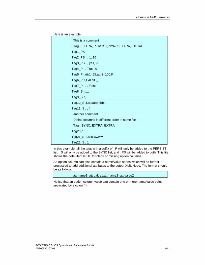
CSV File Format The CSV file format allows blank lines and comment lines which are designated by a leading semicolon (;). The CSV file must have a header with a leading ":TAG" (case does not matter) and at least another column with PERSIST or SYNC (case does not matter). If the option column is missing, then none of the tags will be processed for that option. For example, if the PERSIST column exists, but the SYNC column does NOT, then the tags will only be processed for PERSIST. The TAG column should contain the full WinCC tagname. The option columns should have the value of "0", "f", or "false" (case does not matter) to NOT ENABLE this option for that tag. Any other value including a blank will ENABLE the option for that tag.
Common HMI Elements
PCS 7/APACS+ OS Symbols and Faceplates for V6.1 A5E00595267-01 1-11
Here is an example:
; This is a comment
: Tag , EXTRA, PERSIST, SYNC, EXTRA, EXTRA
Tag1_PS
Tag2_PS , , 1, 10
Tag3_PS , , yes, -1
Tag4_P , , True, 0
Tag5_P,,attr1=55:attr2=100,F
Tag6_P,,t,FALSE,,
Tag7_P , , , False
Tag8_S,,f,,,,
Tag9_S,,f,+
Tag10_S,,f,aaaaa=bbb,,,
Tag11_S , , f
; another comment
; Define columns in different order in same file
: Tag , SYNC, EXTRA, EXTRA
Tag20_S
Tag21_S,+,sss,wwww
Tag22_S , 1
In this example, all the tags with a suffix of _P will only be added to the PERSIST list, _S will only be added to the SYNC list, and _PS will be added to both. This file shows the defaulted TRUE for blank or missing option columns.
An option column can also contain a name/value series which will be further processed to add additional attributes to the output XML Node. The format should be as follows:
attrname1=attrvalue1:attrname2=attrvalue2
Notice that an option column value can contain one or more name/value pairs separated by a colon (:).

Common HMI Elements
1-12 PCS 7/APACS+ OS Symbols and Faceplates for V6.1 A5E00595267-01
The previous example generates the following XML file, assuming the PERSIST and SYNC configurations were empty to start with:
<AppHost>
<PlugIn Name="CustomSyncPersistInjector" ProgID="CustomSyncPersistPlugIn.PlugIn" Enabled="-1" File="Test.csv" Status="LOADED"/>
<PlugIn Name="SyncAgent" ProgID="SyncAgent.EventSync" Enabled="0" Status="LOADED">
<Sync Na="DMAdapter.Tag1_PS" ASONa="??"/>
<Sync Na="DMAdapter.Tag2_PS" ASONa="??"/>
<Sync Na="DMAdapter.Tag3_PS" ASONa="??"/>
<Sync Na="DMAdapter.Tag8_S" ASONa="??"/>
<Sync Na="DMAdapter.Tag9_S" ASONa="??"/>
<Sync Na="DMAdapter.Tag10_S" ASONa="??" aaaaa="bbb"/>
<Sync Na="DMAdapter.Tag11_S" ASONa="??"/>
<Sync Na="DMAdapter.Tag20_S" ASONa="??"/>
<Sync Na="DMAdapter.Tag21_S" ASONa="??"/>
<Sync Na="DMAdapter.Tag22_S" ASONa="??"/>
</PlugIn>
<PlugIn Name="PersistAgent" ProgID="PersistAgent.EventPersist" Enabled="0" Status="LOADED">
<Persist Na="DMAdapter.Tag1_PS" ASONa="??"/>
<Persist Na="DMAdapter.Tag2_PS" ASONa="??"/>
<Persist Na="DMAdapter.Tag3_PS" ASONa="??"/>
<Persist Na="DMAdapter.Tag4_P" ASONa="??"/>
<Persist Na="DMAdapter.Tag5_P" ASONa="??" attr1="55" attr2="100"/>
<Persist Na="DMAdapter.Tag6_P" ASONa="??"/>
<Persist Na="DMAdapter.Tag7_P" ASONa="??"/>
</PlugIn>
</AppHost>
The 'ASONa' attribute is '??', which allows for later enhancements that may need to track which object created the item. It is not currently used.

Common HMI Elements
PCS 7/APACS+ OS Symbols and Faceplates for V6.1 A5E00595267-01 1-13
1.13 Disabled Alarm List A disabled alarm list is available that displays all disabled and locked APACS+ alarms in the system.
It is displayed by clicking the disabled alarm list button on the PCS 7 alarm logging status bar.


PCS 7/APACS+ OS Symbols and Faceplates for V6.1 A5E00595267-01 2-1
2 SINGLE_LOOP_AFB
2.1 SINGLE_LOOP_AFB Standard View

SINGLE_LOOP_AFB
2-2 PCS 7/APACS+ OS Symbols and Faceplates for V6.1 A5E00595267-01
Key Name Type Description Tag
1 IOFieldPV Customized Object Process Variable PV; PV_EUMAX; PV_EUMIN
2 IOFieldSP Customized Object Setpoint SP;SPH; SPL;
3 IOFieldOUT Customized Object Output VL;VLH; VLL
4 PVUnits I/O Field PV units PV#unit
5 SPUnits I/O Field SP units PV#unit
6 OUTUnits I/O Field Output units VL#unit
7 ModeControl Customized Object Mode AUTO
8 Description StaticText Function Block Comment #comment
9 BarLimits Customized Object Alarm limits display PV_EUMAX; PV_EUMIN; HH_LIM; H_LIM; L_LIM; LL_LIM
10 PVSPBargraph Customized Object PV and SP PV; PV_EUMAX; PV_EUMIN; SP;
11 OutputBargraph Customized Object Output display VL; VL_EUMAX; VL_EUMIN;
The mode control Auto selects process automation, while Manual permits operator control of the output. In Auto mode, clicking the SP (set point) box displays an analog input edit box. Clicking is not allowed when the mode is set to Manual and PVTracking is enabled. Range limits are enforced by the SPH and SPL tags.
File: @PG_SINGLE_LOOP_AFB_STANDARD.PDL

SINGLE_LOOP_AFB
PCS 7/APACS+ OS Symbols and Faceplates for V6.1 A5E00595267-01 2-3
2.2 SINGLE_LOOP_AFB Tuning View
1
32
4
5
6
789
1011
Key Name Type Description Tag
1 CheckBoxPVTrack Customized Object PV Tracking Enabled PV_TRACK
2 IOFieldSPH I/O Field SP High Limit SPH
3 IOFieldSPL I/O Field SP Low Limit SPL
4 ActionDirect Static Text Direct Acting DIR
4 ActionReverse Static Text Reverse Acting
5 SPHUnits1 Static Text SP Units PV#unit
5 SPHUnits2 Static Text SP Units PV#unit
6 IOFieldVLH I/O Field VL High Limit VLH
7 IOFieldVLL I/O Field VL Low Limit VLL
8 IOFieldPG I/O Field Proportional Gain PG, DIR
9 IOFieldTI I/O Field Integral Time TI
10 IOFieldTD I/O Field Derivative Time TD
11 IOFieldDG I/O Field Derivative Gain DG
• Clicking the PVTrack check box produces a discrete input confirmation box.
• Clicking any of the eight edit boxes produces an analog input edit box. Range limits (if configured) are enforced by the WinCC Data Manager.
• The controller action (Direct/Reverse) is a read-only field.
File: @PCS7_APACS_TUNING.PDL

SINGLE_LOOP_AFB
2-4 PCS 7/APACS+ OS Symbols and Faceplates for V6.1 A5E00595267-01
2.3 SINGLE_LOOP_AFB Alarm View The alarm view uses a standard WinCC Active X control. No modifications were made to it for the PCS 7 OS option.
File: @PCS7_ALARM.PDL

SINGLE_LOOP_AFB
PCS 7/APACS+ OS Symbols and Faceplates for V6.1 A5E00595267-01 2-5
2.4 SINGLE_LOOP_AFB Ramp View
Key Name Type Description Tag
1 CheckBoxUseRR Customized Object Use Ramp Rate USE_RR
2 RampControl Customized Object Ramp Control RAMP
3 IOFieldTarget I/O Field Target SP TSP
4 TargetUnits Static Text Target SP Units PV#unit
5 IOFieldRate I/O Field SP Ramp Rate R_RATE
6 RateUnits Static Text SP Ramp Rate Units PV#unit
7 IOFieldTime I/O Field SP Ramp Time R_TIME
• Clicking the Use Ramp Rate check box will cause the “Rate” value below to be used to specify the ramping, and the “Time” value will be ignored. Otherwise, Time is used and Rate is ignored. A discrete input confirmation dialog will appear if ConfirmChange is TRUE.
• Clicking the Ramp Status edit box produces a discrete input confirmation box, if ConfirmChange is TRUE.
• Clicking any of the three edit boxes produces an analog input edit box. Range limits (if configured) are enforced by the WinCC Data Manager.
File: @PCS7_APACS_RAMP.PDL

SINGLE_LOOP_AFB
2-6 PCS 7/APACS+ OS Symbols and Faceplates for V6.1 A5E00595267-01
2.5 SINGLE_LOOP_AFB Limits View
Key Name Type Description Tag
1 CheckBoxHHEN Customized Object High High Alarm Enable HH_EN
1 CheckBoxHEN Customized Object High Alarm Enable H_EN
1 CheckBoxLEN Customized Object Low Alarm Enable L_EN
1 CheckBoxLLEN Customized Object Low LowAlarm Enable LL_EN
1 CheckBoxHDEN Customized Object High Deviation Alarm Enable HD_EN
1 CheckBoxLDEN Customized Object Low Deviation Alarm Enable LD_EN
1 CheckBoxADEN Customized Object Absolute Deviation Alarm Enable AD_EN
1 CheckBoxIREN Customized Object Increasing ROC Alarm Enable IR_EN
1 CheckBoxDREN Customized Object Decreasing ROC Alarm Enable DR_EN
1 CheckBoxAREN Customized Object Absolute ROC Alarm Enable AR_EN
1 CheckBoxOOREN Customized Object Out Of Range Alarm Enable OOR_EN
1 CheckBoxQUALEN Customized Object Quality Alarm Enable QUAL_EN
2 IOFieldHHLimit I/O Field High High Alarm Limit HH_LIM
2 IOFieldHLimit I/O Field High Alarm Limit H_LIM
2 IOFieldLLimit I/O Field Low Alarm Limit L_LIM
2 IOFieldLLLimit I/O Field Low LowAlarm Limit LL_LIM
2 IOFieldHDLimit I/O Field High Deviation Alarm Limit HD_LIM
2 IOFieldLDLimit I/O Field Low Deviation Alarm Limit LD_LIM

SINGLE_LOOP_AFB
PCS 7/APACS+ OS Symbols and Faceplates for V6.1 A5E00595267-01 2-7
Key Name Type Description Tag
2 IOFieldADLimit I/O Field Absolute Deviation Alarm Limit AD_LIM
2 IOFieldIRLimit I/O Field Increasing ROC Alarm Limit IR_LIM
2 IOFieldDRLimit I/O Field Decreasing ROC Alarm Limit DR_LIM
2 IOFieldARLimit I/O Field Absolute ROC Alarm Limit AR_LIM
2 IOFieldHHDB I/O Field High High Alarm Deadband HH_DB
2 IOFieldHDB I/O Field High Alarm Deadband H_DB
2 IOFieldLDB I/O Field Low Alarm Deadband L_DB
3 IOFieldLLDB I/O Field Low LowAlarm Deadband LL_DB
3 IOFieldHDDB I/O Field High Deviation Alarm Deadband HD_DB
3 IOFieldLDDB I/O Field Low Deviation Alarm Deadband LD_DB
3 IOFieldADDB I/O Field Absolute Deviation Alarm Deadband AD_DB
3 IOFieldIRDB I/O Field Increasing ROC Alarm Deadband IR_DB
3 IOFieldDRDB I/O Field Decreasing ROC Alarm Deadband DR_DB
3 IOFieldARDB I/O Field Absolute ROC Alarm Deadband AR_DB
4 HHUnits Static Text High High Alarm Limit Units PV#unit
4 HUnits Static Text High Alarm Limit Units PV#unit
4 LUnits Static Text Low Alarm Limit Units PV#unit
4 LLUnits Static Text Low LowAlarm Limit Units PV#unit
4 HDUnits Static Text High Deviation Alarm Limit Units PV#unit
4 LDUnits Static Text Low Deviation Alarm Limit Units PV#unit
4 ADUnits Static Text Absolute Deviation Alarm Limit Units PV#unit
4 IRUnits Static Text Increasing ROC Alarm Limit Units PV#unit
4 DRUnits Static Text Decreasing ROC Alarm Limit Units PV#unit
4 ARUnits Static Text Absolute ROC Alarm Limit Units PV#unit
• Clicking any check box produces a discrete input confirmation box, if the ConfirmChange attribute for this block is TRUE.
• Clicking any of the edit boxes produces an analog input edit box. Range limits (if configured) are enforced by the WinCC Data Manager.
• In the case of the APACS+ ported blocks running in the PCS 7 OS, all of the user editable fields are available and enabled. In the case of the APACS+ blocks running in an ACM or CCM, the function block will have at most four of twelve alarm types configured. The fields for each unused alarm type are hidden in the user interface. This will happen automatically because the PCS 7 OS attribute of the field is not mapped to the ACM or CCM.
File: @PCS7_APACS_ALARM_CONFIG.PDL

SINGLE_LOOP_AFB
2-8 PCS 7/APACS+ OS Symbols and Faceplates for V6.1 A5E00595267-01
2.6 SINGLE_LOOP_AFB Trend View The trend view is the standard view for displaying trends for the function block. For the SINGLE_LOOP_AFB function block the trend view displays the process value (PV), setpoint (SP), and output value (VL). Only one trend window is needed for each function block type. A script assigns proper tags to the trend control at runtime.
The standard PCS 7 OS trend view is available for use with APACS+ function blocks through normal PCS 7 OS procedures and configuration.
The illustration below shows the trend view with rulers enabled.
8
2
1
3 46
7
11
10
9
12
5

SINGLE_LOOP_AFB
PCS 7/APACS+ OS Symbols and Faceplates for V6.1 A5E00595267-01 2-9
Key Description
1 Ruler (see key 12)
2 Zoom
3 Original view (return from zoom)
4 Select time range
5 Previous trend
6 Next trend
7 Stop (freeze)/start (continue)
8 Moveable cursor, shown when ruler, key 1, is enabled
9 SP (blue)
10 PV (green)
11 VL (orange)
12 Detachable window displayed when ruler (see key 1) is enabled. Shows process values at cursor position, which can be dragged. Color coded with trend curves.
File: @PCS7_APACS_TREND3.PDL
2.7 SINGLE_LOOP_AFB Faceplate Overview Window
Key Description
1 Alarm Group Display
2 Lock/unlock messages button
3 Alarm ACK button
4 Go to primary graphic button (display function block's primary graphic)
File: @PG_SINGLE_LOOP_AFB_OVERVIEW.PDL
SINGLE_LOOP_AFB
2-10 PCS 7/APACS+ OS Symbols and Faceplates for V6.1 A5E00595267-01
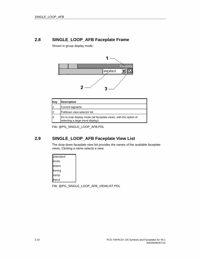
2.8 SINGLE_LOOP_AFB Faceplate Frame Shown in group display mode:
Key Description
1 Current tagname
2 Pulldown view-selector list
3 Go to loop display mode (all faceplate views, with the option of selecting a large trend display)
File: @PG_SINGLE_LOOP_AFB.PDL
2.9 SINGLE_LOOP_AFB Faceplate View List The drop-down faceplate view list provides the names of the available faceplate views. Clicking a name selects a view.
File: @PG_SINGLE_LOOP_AFB_VIEWLIST.PDL

SINGLE_LOOP_AFB
PCS 7/APACS+ OS Symbols and Faceplates for V6.1 A5E00595267-01 2-11
2.10 SINGLE_LOOP_AFB Loop Display Mode The loop display mode provides all six of the available single loop faceplates. It is not the default mode, and must be invoked from the initial (standard) view faceplate by the loop display mode button:
From the loop display mode, you can expand the trend display to cover four views by clicking Display Large Trend. With the loop display expanded, you can shrink it to cover a single view by clicking Display Small Trend.

SINGLE_LOOP_AFB
2-12 PCS 7/APACS+ OS Symbols and Faceplates for V6.1 A5E00595267-01
2.11 SINGLE_LOOP_AFB View .PDL Files The following table lists the PCS 7 OS graphic files (.PDLs) that create the OS HMI for the SINGLE_LOOP_AFB views. These files can be opened and examined with the WinCC Graphics Designer program: Start > Simatic > WinCC > WinCC> (open project) > Graphics Designer (right click) > Open (select .PDL file) > Open.
View File
Standard @PG_SINGLE_LOOP_AFB_STANDARD.PDL
Tuning @PCS7_APACS_TUNING.PDL
Alarm @PCS7_ALARM.PDL
Ramp @PCS7_APACS_RAMP.PDL
Limits @PCS7_APACS_ALARM_CONFIG.PDL
Trend @PCS7_APACS_TREND3.PDL
Faceplate Overview Window
@PG_SINGLE_LOOP_AFB_OVERVIEW.PDL
Faceplace Frame @PG_SINGLE_LOOP_AFB.PDL
Faceplate View List @PG_SINGLE_LOOP_AFB_VIEWLIST.PDL
Faceplate Loop @PL_SINGLE_LOOP_AFB.PDL

PCS 7/APACS+ OS Symbols and Faceplates for V6.1 A5E00595267-01 3-1
3 Other Faceplates
3.1 ANALOG_ALM_AFB
Standard View The Standard view is the default view when the faceplate is first displayed in Group Display mode. It displays the function block description, process variable, and some alarm limits.
The standard view contains a subset of the elements in the PG_SINGLE_LOOP_AFB_STANDARD.PDL file.
See the SINGLE_LOOP_AFB section for details on the remaining elements.
Faceplate View List The drop-down faceplate view list provides the names of the available faceplate views. Clicking a name selects a view.

Other Faceplates
3-2 PCS 7/APACS+ OS Symbols and Faceplates for V6.1 A5E00595267-01
Faceplate Loop View The loop view of the faceplate, displayed by clicking the loop display mode button on the group faceplate, displays all four faceplate views in one window.
Clicking the Display Large Trend button increases the size of the trend view by four times and places it on top of two of four smaller views. Clicking the Display Small Trend button restores the trend view to the original size.
View .PDL Files
View File
Standard @PG_ANALOG_ALM_AFB_STANDARD.PDL
Alarm @PCS7_ALARM.PDL (see the SINGLE_LOOP_AFB)
Limits @PCS7_APACS_ALARM_CONFIG.PDL (see the SINGLE_LOOP_AFB)
Trend View (one pen) @PCS7_APACS_TREND1.PDL (see the SINGLE_LOOP_AFB)
Faceplace Frame @PG_ANALOG_ALM_AFB.PDL (see the SINGLE_LOOP_AFB)
Faceplate Overview Window
@PG_ANALOG_ALM_AFB_OVERVIEW.PDL (see the SINGLE_LOOP_AFB)
Faceplate View List @PG_ANALOG_ALM_AFB_VIEWLIST.PDL
Faceplate Loop @PL_ANALOG_ALM_AFB.PDL

Other Faceplates
PCS 7/APACS+ OS Symbols and Faceplates for V6.1 A5E00595267-01 3-3
3.2 DISCRETE_ALM_AFB
Standard View The Standard view is the default view when the faceplate is first displayed in Group Display mode. It displays the function block description, alarm status, and certain alarm configuration values.
The following table lists all of the significant objects on the view: Key Name Type Description Tag
1 StaticTextOn Static Text On Indicator DIN, DIN#string_1
StaticTextOff Static Text Off Indicator DIN#string_0
2 Description Static Text FB comment #comment
3 CheckBoxEN Customized object
Enabled EN
4 AlarmHighText Static Text Alarm Type High LIM
AlarmLowText Static Text Alarm Type Low
Clicking the Enabled check box displays a discrete input confirmation box and asks for confirmation of changes, if the ConfirmChange attribute of the block is TRUE.

Other Faceplates
3-4 PCS 7/APACS+ OS Symbols and Faceplates for V6.1 A5E00595267-01
Faceplate View List The drop-down faceplate view list provides the names of the available faceplate views. Clicking a name selects a view.
Faceplate Loop View Clicking the loop display mode button on the group faceplate displays both faceplate views in one window.
View .PDL Files Unless otherwise indicated, faceplate views listed in the table below are identical or similar to corresponding views for the SINGLE_LOOP_AFB. See the SINGLE_LOOP_AFB sections for more information.
View File
Standard @PG_DISCRETE_ALM_AFB_STANDARD.PDL
Alarm @PCS7_ALARM.PDL (see the SINGLE_LOOP_AFB)
Faceplate Frame @PG_DISCRETE_ALM_AFB.PDL (see the SINGLE_LOOP_AFB)
Faceplate Overview Window
@PG_DISCRETE_ALM_AFB_OVERVIEW.PDL (see the SINGLE_LOOP_AFB)
Faceplate View List @PG_DISCRETE_ALM_AFB_VIEWLIST.PDL
Faceplate Loop @PL_DISCRETE_ALM_AFB.PDL

Other Faceplates
PCS 7/APACS+ OS Symbols and Faceplates for V6.1 A5E00595267-01 3-5
3.3 MOTOR_1OUT_AFB
Standard View The Standard view is the default view when the faceplate is first displayed in Group Display mode. It displays the function block description, alarm status, and various motor status values and motor configuration values.
Operation and Controls • The On/Off indicator displays the current state of the MOTOR.
• The Out indicator displays the output of the function block.
• The Interlock indicator displays the current interlock status of the function block.
• The Start and Stop buttons allow operator control of the MOTOR. These buttons are only enabled when the function block is in Manual mode. Clicking the Start or Stop buttons brings up a confirmation box, if the ConfirmChange attribute of the block is TRUE.
• The Mode indicator displays the current mode of the function block (Auto/Manual).

Other Faceplates
3-6 PCS 7/APACS+ OS Symbols and Faceplates for V6.1 A5E00595267-01
• The Start Time indicator displays the maximum allowable time between the OUT signal going TRUE and PROOF feedback going TRUE before the FAIL output goes TRUE. A time to start MOTOR in excess of this value fires an alarm. Clicking the Start Time or Stop Time I/O field brings up a time input edit box.
• The Stop Time indicator displays the maximum allowable time between the OUT signal going FALSE and PROOF feedback going FALSE before the FAIL output goes TRUE. A time to stop MOTOR in excess of this value fires an alarm. Clicking the Start Time or Stop Time I/O field brings up a time input edit box.
• The Enabled check box controls the discrete alarm of the function block.
Objects The following table lists all of the significant objects on the standard view:
Key Name Type Description Tag
1 StaticTextOn Static Text Motor on Indicator PROOF
2 StaticTextOff Static Text Motor off Indicator PROOF
StaticTextOff1 Static Text Motor off Indicator
3 StaticTextOutStart Static Text Output Start Indicator OUT
StaticTextOutStop Static Text Output Stop Indicator
4 StaticTextInterlockOK Static Text Intorlock OK Indicator INTRLK
StaticTextInterlocked Static Text Intorlocked Indicator
5 Description Static Text FB comment #comment
6 ButtonStart Customized object Start MOTOR Control START, AUTO
7 ButtonStop Customized object Stop MOTOR Control STOP, AUTO
8 ModeControl Customized object Mode AUTO
9 IOFieldStartTime Customized object Start time limit START_T
10 IOFieldStopTime Customized object Stop time limit STOP_T
11 CheckBoxEN Customized object Enabled A1EN
Faceplate View List The drop-down faceplate view list provides the names of the available faceplate views. Clicking a name selects a view.

Other Faceplates
PCS 7/APACS+ OS Symbols and Faceplates for V6.1 A5E00595267-01 3-7
Faceplate Loop View Clicking the loop display mode button on the group faceplate displays both faceplate views in one window.
View .PDL Files View File
Standard @PG_MOTOR_1OUT_AFB_STANDARD.PDL
Alarm View @PCS7_ALARM.PDL (see the SINGLE_LOOP_AFB)
Faceplate Frame @PG_MOTOR_1OUT_AFB.PDL (see the SINGLE_LOOP_AFB)
Faceplate Overview Window @PG_MOTOR_1OUT_AFB_OVERVIEW.PDL (see the SINGLE_LOOP_AFB)
Faceplate View List @PG_MOTOR_1OUT_AFB_VIEWLIST.PDL
Faceplate Loop View @PL_MOTOR_1OUT_AFB.PDL

Other Faceplates
3-8 PCS 7/APACS+ OS Symbols and Faceplates for V6.1 A5E00595267-01
3.4 MOTOR_2OUT_AFB See MOTOR_1OUT_AFB for information about operation and controls.
View .PDL Files View File
Standard @PG_MOTOR_2OUT_AFB_STANDARD.PDL
Alarm View @PCS7_ALARM.PDL (see the SINGLE_LOOP_AFB)
Faceplate Frame @PG_MOTOR_2OUT_AFB.PDL (see the SINGLE_LOOP_AFB)
Faceplate Overview Window
@PG_MOTOR_2OUT_AFB_OVERVIEW.PDL (see the SINGLE_LOOP_AFB)
Faceplate View List @PG_MOTOR_2OUT_AFB_VIEWLIST.PDL
Faceplate Loop View @PL_MOTOR_2OUT_AFB.PDL

Other Faceplates
PCS 7/APACS+ OS Symbols and Faceplates for V6.1 A5E00595267-01 3-9
3.5 MOTOR_A_AFB
Standard View The standard view is the default view when the faceplate is first displayed in Group Display mode. It displays the function block description, alarm status, and various motor status values and motor configuration values.
Operation and Controls • The On/Off indicators display the current state of the MOTOR. Only one is
visible at a time. They are controlled by one tag, PROOF.
• The Out indicator displays the output of the function block.
• The Override indicator displays the current override status of the function block.
• The Permit indicator displays the current permit status of the function block.
• The Interlock indicator displays the current interlock status of the function block.
• The Start and Stop buttons allow operator control of the MOTOR. These buttons are only enabled when the function block is in Manual mode.
• The Mode indicator displays the current mode of the function block (Auto/Manual).
• The Failure Reset button lets operator clear the failure output.

Other Faceplates
3-10 PCS 7/APACS+ OS Symbols and Faceplates for V6.1 A5E00595267-01
• The Start Time indicator displays the maximum allowable time between the OUT signal going TRUE and PROOF feedback going TRUE before the FAIL output goes TRUE. A time to start MOTOR in excess of this value fires an alarm.
• The Stop Time indicator displays the maximum allowable time between the OUT signal going FALSE and PROOF feedback going FALSE before the FAIL output goes TRUE. A time to stop MOTOR in excess of this value fires an alarm.
• Clicking the Start, Stop or Reset buttons brings up a confirmation box and asks the user to confirm the change, if the ConfirmChange attribute is TRUE. Start and Stop buttons are only enabled when the function block is in Manual mode. The Failure Reset button is enabled when the tag FAIL is true.
Objects The following table lists all of the significant objects on the standard view:
Key Name Type Description Tag
1 StaticTextOn Static Text Motor on Indicator PROOF
2 StaticTextOff Static Text Motor off Indicator PROOF
3 StaticTextOutStart Static Text Output Start Indicator OUT
StaticTextOutStop Static Text Output Stop Indicator
4 StaticTextOverride Static Text Override Indicator OVERRD
StaticTextPermitOverride Static Text Permit Indicator OVERRD
5 StaticTextPermitOK Static Text Permit Indicator PERMIT
StaticTextNotPermitted Static Text Permit Indicator
6 StaticTextInterlockOK Static Text Intorlock OK Indicator INTRLK
StaticTextInterlocked Static Text Intorlocked Indicator
7 Description Static Text FB comment #comment
8 ButtonStart Customized object
Start MOTOR Control START, AUTO
9 ButtonStop Customized object
Stop MOTOR Control STOP, AUTO
10 ModeControl Customized object
Mode AUTO
11 ButtonReset Customized object
Reset Failure Output Control FAIL
12 IOFieldStartTime Customized object
Start time limit STRT_T
13 IOFieldStopTime Customized object
Stop time limit STOP_T

Other Faceplates
PCS 7/APACS+ OS Symbols and Faceplates for V6.1 A5E00595267-01 3-11
Faceplate View List The drop-down faceplate view list provides the names of the available faceplate views. Clicking a name selects a view.
Interlocks View The interlocks view is the same view used by the VALVE_A_AFB faceplate. See the VALVE_A_AFB section for details.
Faceplate Loop View Clicking the loop display mode button on the group faceplate displays three faceplate views in one window.
View .PDL Files View File
Standard @PG_MOTOR_A_AFB_STANDARD.PDL
Alarm @PCS7_ALARM.PDL (see the SINGLE_LOOP_AFB)
Faceplate Frame @PG_MOTOR_A_AFB.PDL (see the SINGLE_LOOP_AFB)
Interlocks @PCS7_APACS_INTERLOCKS.PDL (see VALVE_A_AFB)
Faceplate Overview Window @PG_MOTOR_A_AFB_OVERVIEW.PDL (see the SINGLE_LOOP_AFB)
Faceplate View List @PG_MOTOR_A_AFB_VIEWLIST.PDL
Faceplate Loop @PL_MOTOR_A_AFB.PDL

Other Faceplates
3-12 PCS 7/APACS+ OS Symbols and Faceplates for V6.1 A5E00595267-01
3.6 MOTOR_A_ALM_AFB See the MOTOR_A_AFB section.
Operation and Controls Clicking the Enabled check box invokes a discrete input confirmation box, if the ConfirmChange attribute is TRUE.
Limits View The Limits view shows the alarm configuration of the function block. Note that this faceplate view is not specific to the MOTOR_A_ALM function block. Every function block that implements discrete alarms references this .PDL file.
The Type indicators display the alarm type. These types are hard coded. For MOTOR_A_ALM, they are displayed in the illustration that follows.
Objects The following table lists all of the significant objects on the view:
Key Name Type Description Tag
1 CheckBoxA1EN Customized object A1 Alarm Enabled A1EN
2 CheckBoxA2EN Customized object A2 Alarm Enabled A2EN
3 CheckBoxA3EN Customized object A3 Alarm Enabled A3EN
4 CheckBoxA4EN Customized object A4 Alarm Enabled A4EN

Other Faceplates
PCS 7/APACS+ OS Symbols and Faceplates for V6.1 A5E00595267-01 3-13
Faceplate View List The drop-down faceplate view list provides the names of the available faceplate views. Clicking a name selects a view.
Interlocks View The interlocks view is the same view used by the VALVE_A_AFB faceplate. See the VALVE_A_AFB section for details.
Faceplate Loop View The loop view of the faceplate, displayed by clicking the loop display mode button on the group faceplate, displays all four faceplate views in one window.

Other Faceplates
3-14 PCS 7/APACS+ OS Symbols and Faceplates for V6.1 A5E00595267-01
View .PDL Files View File
Standard @PG_MOTOR_A_ALM_AFB_STANDARD.PDL (see the SINGLE_LOOP_AFB)
Alarm @PCS7_ALARM.PDL (see the SINGLE_LOOP_AFB)
Faceplate Frame @PG_MOTOR_A_ALM_AFB.PDL (see the SINGLE_LOOP_AFB)
Interlocks @PCS7_APACS_INTERLOCKS.PDL (see the VALVE_A_AFB section)
Limits @PCS7_APACS_DISCRETE_ALARM_CONFIG.PDL
Faceplate View List @PG_MOTOR_A_ALM_AFB_VIEWLIST.PDL
Faceplate Overview Window
@PG_MOTOR_A_ALM_AFB_OVERVIEW.PDL (see the SINGLE_LOOP_AFB)
Faceplate Loop View @PL_MOTOR_A_ALM_AFB.PDL

Other Faceplates
PCS 7/APACS+ OS Symbols and Faceplates for V6.1 A5E00595267-01 3-15
3.7 BLK_VLV_1OUT_AFB
Standard View The Standard view is the default view when the faceplate is first displayed in Group Display mode. It displays the function block description, alarm status, and various valve status values and valve configuration values.
1234
6 7
8
9
10
115
12
Operation and Controls • The Open/Travel/Close indicator displays the current state of the valve.
• The Out indicator displays the output of the function block.
• The Interlock indicator displays the current interlock status of the function block.
• The Open and Close buttons allow operator control of the valve. These buttons are only enabled when the function block is in Manual mode.
• The Mode indicator displays the current mode of the function block (Auto/Manual), and allows the user to change the mode.
• The Travel Time indicator displays the configured travel time of the function block. A valve travel time in excess of this value fires an alarm.
• The Enabled check box controls the 1 discrete alarm of the function block.
• The Alarm Type indicator displays the alarm type. In the case of the BLK_VLV_1OUT_AFB function block, this is always HIGH.

Other Faceplates
3-16 PCS 7/APACS+ OS Symbols and Faceplates for V6.1 A5E00595267-01
• Clicking the Open or Close buttons brings up a confirmation box, if the ConfirmChange attribute is TRUE. These buttons are only enabled when the function block is in Manual mode.
• Clicking the ModeControl box displays a discrete input confirmation box, if the ConfirmChange attribute is TRUE and asks the user to select a choice from the radio buttons displayed.
• Clicking the Enabled check box brings up a discrete input confirmation box, if the ConfirmChange attribute is TRUE.
• Clicking the Travel Time I/O field brings up a time input edit box.
Objects The following table lists all of the significant objects on the view:
Key Name Type Description Tag
1 StaticTextOpen Static Text Open Indicator OP_VER
2 StaticTextClose Static Text Travel Indicator TRANS
3 StaticTextTravel Static Text Close Indicator CL_VER
4 StaticTextOutOpen Static Text Output Open Indicator OUT
StaticTextOutClose Static Text Output Close Indicator
5 StaticTextInterlockOK Static Text Intorlock OK Indicator INTRLK
StaticTextInterlocked Static Text Intorlocked Indicator
6 Description Static Text FB comment #comment
7 ButtonOpen Customized object
Open Valve Control OPEN, AUTO
8 ButtonClose Customized object
Close Valve Control CLOSE, AUTO
9 ModeControl Customized object
Mode AUTO
10 IOFieldTravelTime Customized object
Travel Time Limit TRAV_T
11 CheckBoxEN Customized object
Enabled A1EN
12 AlarmTypeLabel Static Text Alarm Type Label
Faceplate View List The drop-down faceplate view list provides the names of the available faceplate views. Clicking a name selects a view.

Other Faceplates
PCS 7/APACS+ OS Symbols and Faceplates for V6.1 A5E00595267-01 3-17
Faceplate Loop View The loop view of the faceplate, displayed by clicking the loop display mode button on the group faceplate, displays all four faceplate views in one window.
View .PDL Files View File
Standard @PG_BLK_VLV_1OUT_AFB_STANDARD.PDL
Alarm @PCS7_ALARM.PDL (see the SINGLE_LOOP_AFB)
Faceplate Frame @PG_BLK_VLV_1OUT_AFB.PDL (see the SINGLE_LOOP_AFB)
Interlocks @PCS7_APACS_INTERLOCKS.PDL (see the VALVE_A_AFB section)
Faceplate View List @PG_BLK_VLV_1OUT_AFB_VIEWLIST.PDL
Faceplate Overview Window
@PG_BLK_VLV_1OUT_AFB_OVERVIEW.PDL (see the SINGLE_LOOP_AFB)
Faceplate Loop View @PL_BLK_VLV_1OUT_AFB.PDL
3.8 BLK_VLV_2OUT_AFB The BLK_VLV_2OUT_AFB faceplate is identical in every respect to the BLK_VLV_1OUT_AFB except in the names of the PDL files and any associated attribute values.
In addition, the .OPEN_LATCH parameter is exposed as the OUT tag in the mapper template file instead of the .[OUT] for BLK_VLV_1OUT_AFB
See the BLK_VLV_1OUT_AFB section for details.

Other Faceplates
3-18 PCS 7/APACS+ OS Symbols and Faceplates for V6.1 A5E00595267-01
3.9 VALVE_A_AFB
Standard View The Standard view is the default view when the faceplate is first displayed in Group Display mode. It displays the function block description, alarm status, and various valve status values and valve configuration values.
Operation and Controls • The Open/Travel/Close indicator displays the current state of the valve.
• The Out indicator displays the output of the function block.
• The Override indicator displays the current override status of the function block.
• The Permit indicator displays the current permit status of the function block.
• The Interlock indicator displays the current interlock status of the function block.
• The Open and Close buttons allow operator control of the valve. These buttons are only enabled when the function block is in Manual mode.
• The Mode indicator displays the current mode of the function block (Auto/Manual), and allows the user to change the mode.
• The Failure Reset button allows the operator to clear the valve’s FAIL status. This button is only enabled when the function block is in a failed state.

Other Faceplates
PCS 7/APACS+ OS Symbols and Faceplates for V6.1 A5E00595267-01 3-19
• The Open Time indicator displays the configured travel time of the function block. A valve open time in excess of this value fires an alarm.
• The Close Time indicator displays the configured travel time of the function block. A valve close time in excess of this value fires an alarm.
• Clicking the Permit or Interlock indicators switches to the Interlock view. If the faceplate is in loop display mode, this action is ignored since the interlocks view is already being displayed.
• Clicking the Open or Close buttons brings up a confirmation box, if ConfirmChange is TRUE. These buttons are only enabled when the function block is in Manual mode.
• Clicking the Reset button brings up a confirmation box, if ConfirmChange is TRUE. This button is only enabled when the function block is in FAIL mode.
• Clicking the ModeControl box displays a discrete input confirmation box, if ConfirmChange is TRUE and asks the user to select a choice from the radio buttons displayed.
• Clicking the Open Time or Close Time I/O fields displays a time input edit box.
Standard View Objects The following table lists all of the significant objects on the view:
Key Name Type Description Tag
1 StaticTextOpen Static Text Open Indicator OP_VER
2 StaticTextClose Static Text Travel Indicator OP_VER,CL_VER
3 StaticTextTravel Static Text Close Indicator CL_VER
4 StaticTextOutOpen Static Text Output Open Indicator OUT
StaticTextOutClose Static Text Output Close Indicator
5 StaticTextOverride Static Text Override Indicator OVERRD
6 StaticTextPermitOK Static Text Permit OK Indicator PERMIT
StaticTextPermitOverrideOK Static Text Permit OK Indicator OVERRD
StaticTextNotPermitted Static Text Not Permitted Indicator
7 StaticTextInterlockOK Static Text Intorlock OK Indicator INTRLK
StaticTextInterlocked Static Text Intorlocked Indicator
8 Description Static Text FB comment #comment
9 ButtonOpen Customized object Open Valve Control OPEN, AUTO
10 ButtonClose Customized object Close Valve Control CLOSE, AUTO
11 ModeControl Customized object Mode AUTO
12 ButtonReset Customized object Valve Reset control FAIL
13 IOFieldOpenTime Customized object Open Time Limit OPEN_T
14 IOFieldCloseTime Customized object Close Time Limit CLOSE_T

Other Faceplates
3-20 PCS 7/APACS+ OS Symbols and Faceplates for V6.1 A5E00595267-01
Interlocks View The Interlocks view displays permit status and description, and interlock status and descriptions. It also allows the user to place the block into and out of override mode. Note that this faceplate view is not specific to the VALVE_A_AFB function block. Every function block that implements multiple interlock inputs references this .PDL file.
The Interlocks view actually has 11 interlock status indicators. The VALVE_A and VALVE_A_ALM blocks only have 10 interlock inputs, so the 11th indicator is hidden in these cases. The MOTOR_A and MOTOR_A_ALM blocks, which have 11 interlock inputs, will display all 11 indicators.
Interlock indicators are displayed for all interlock inputs that have a non-blank interlock description. Unused or unconfigured interlocks should be configured with a blank interlock description in 4-mation. The faceplate will not display indicators for these unused interlocks.
Interlocks Operation and Controls • The Override button allows the operator to put the block into override. This
button is only enabled when the function block is not in override.
• The Clear Override button allows the operator to take the block out of override. This button is only enabled when the function block is in override.

Other Faceplates
PCS 7/APACS+ OS Symbols and Faceplates for V6.1 A5E00595267-01 3-21
• Status Indicators (12): In each case, the description is displayed for the appropriate input. If the input is TRUE (1) the text is black on a green background. If the input is FALSE (0) the text is white on a red background. If the description for an interlock is NULL, its Status indicator will be blank (same as gray background) regardless of TRUE or FALSE value. This generally means that this interlock is not in use and has a default value of TRUE. However, there is the possibility that an interlock is in use but has no description configured in the block (by oversight) and in the case, the operator will not be able to see the Status indicator of the interlock that may be preventing valve operation.
• Clicking the Override button brings up a confirmation box, if ConfirmChange is TRUE. This button is only enabled when the function block is not in override mode.
• Clicking the Clear Override button brings up a confirmation box, if ConfirmChange is TRUE. This button is only enabled when the function block is in override mode.
Interlock Objects The following table lists all of the significant objects on the view:
Key Name Type Description Tag
1 StaticTextPermit Static Text Permit Indicator PERMIT, PERMIT_DESC
2 StaticTextInterlock1 Static Text Interlock 1 Indicator INT01, INT01_DESC
2 StaticTextInterlock2 Static Text Interlock 2 Indicator INT02, INT02_DESC
2 StaticTextInterlock3 Static Text Interlock 3 Indicator INT03, INT03_DESC
2 StaticTextInterlock4 Static Text Interlock 4 Indicator INT04, INT04_DESC
2 StaticTextInterlock5 Static Text Interlock 5 Indicator INT05, INT05_DESC
2 StaticTextInterlock6 Static Text Interlock 6 Indicator INT06, INT06_DESC
2 StaticTextInterlock7 Static Text Interlock 7 Indicator INT07, INT07_DESC
2 StaticTextInterlock8 Static Text Interlock 8 Indicator INT08, INT08_DESC
2 StaticTextInterlock9 Static Text Interlock 9 Indicator INT09, INT09_DESC
2 StaticTextInterlock10 Static Text Interlock 10 Indicator INT10, INT10_DESC
2 StaticTextInterlock11 Static Text Interlock 11 Indicator INT11, INT11_DESC
3 ButtonOverride Customized object
Open Valve Control OPEN, AUTO
4 ButtonClearOverride Customized object
Close Valve Control CLOSE, AUTO
Faceplate View List The drop-down faceplate view list provides the names of the available faceplate views. Clicking a name selects a view.

Other Faceplates
3-22 PCS 7/APACS+ OS Symbols and Faceplates for V6.1 A5E00595267-01
Faceplate Overview Window The faceplate frame is the same view used by the SINGLE_LOOP_AFB faceplate, but renamed. See the SINGLE_LOOP_AFB section for details.
Faceplate Loop View The loop display mode displays all three faceplates. It is not the default mode, and must be invoked from the initial (standard) view faceplate by the loop display mode button:
View .PDL Files View File
Standard @PG_VALVE_A_AFB_STANDARD.PDL
Interlocks @PCS7_APACS_INTERLOCKS.PDL
Alarm @PCS7_ALARM.PDL (see the SINGLE_LOOP_AFB)
Faceplate Frame @PG_VALVE_A_AFB.PDL (see the SINGLE_LOOP_AFB)
Interlocks @PCS7_APACS_INTERLOCKS.PDL
Faceplate View List @PG_VALVE_A_AFB_VIEWLIST.PDL
Faceplate Overview Window @PG_VALVE_A_AFB_OVERVIEW.PDL (see the SINGLE_LOOP_AFB)
Faceplate Loop View @PL_VALVE_A_AFB.PDL

Other Faceplates
PCS 7/APACS+ OS Symbols and Faceplates for V6.1 A5E00595267-01 3-23
3.10 VALVE_A_ALM_AFB
Standard View The standard view is the same view used by the VALVE_A_AFB faceplate, but renamed. See the VALVE_A_AFB section for details.
Interlocks View The interlocks view is the same view used by the VALVE_A_AFB faceplate. See the VALVE_A_AFB section for details.
Limits View The Limits view is the same view used by the MOTOR_A_ALM_AFB faceplate, but renamed AS follows For VALVE_A_ALM:
• Failure to close
• Failure to open
• Uncommanded close/open or rejected command (due to interlock)
• Failed limit switch (open and close verify inputs are set)
The Enabled check boxes control the enabled status of the alarms.
See the MOTOR_A_ALM_AFB section for details.
Alarm View The Alarm view is the same view used by the SINGLE_LOOP_AFB faceplate. See the SINGLE_LOOP_AFB section for details.
Faceplate Frame The faceplate frame is the same view used by the SINGLE_LOOP_AFB faceplate, but renamed. See the SINGLE_LOOP_AFB section for details.
Faceplate View List The drop-down faceplate view list provides the names of the available faceplate views. Clicking a name selects a view.

Other Faceplates
3-24 PCS 7/APACS+ OS Symbols and Faceplates for V6.1 A5E00595267-01
Faceplate Overview Window The faceplate frame is the same view used by the SINGLE_LOOP_AFB faceplate, but renamed. See the SINGLE_LOOP_AFB section for detail
Faceplate Loop View The loop display mode displays all four faceplates. It is not the default mode, and must be invoked from the initial (standard) view faceplate by the loop display mode button:
View .PDL Files View File
Standard @PG_VALVE_A_ALM_AFB_STANDARD.PDL (See the VALVE_A_AFB)
Interlocks @PCS7_APACS_INTERLOCKS.PDL (See the VALVE_A_AFB)
Limits @PCS7_APACS_DISCRETE_ALARM_CONFIG.PDL (See the MOTOR_A_ALM_AFB)
Alarm @PCS7_ALARM.PDL (see the SINGLE_LOOP_AFB)
Faceplate Frame @PG_VALVE_A_ALM_AFB.PDL (see the SINGLE_LOOP_AFB)
Faceplate View List @PG_VALVE_A_ALM_AFB_VIEWLIST.PDL
Faceplate Overview Window
@PG_VALVE_A_ALM_AFB_OVERVIEW.PDL (see the SINGLE_LOOP_AFB)
Faceplate Loop View @PL_VALVE_A_ALM_AFB.PDL

Other Faceplates
PCS 7/APACS+ OS Symbols and Faceplates for V6.1 A5E00595267-01 3-25
3.11 EXT_SET_AFB The EXT_SET_AFB faceplate is identical to the SINGLE_LOOP_AFB faceplate except for the addition of four tags as follows: Tag Type Description ACM Source
ESP FLOAT External Setpoint .SETPOINT.[ESP]
EXTRNL BIT External/Internal .SETPOINT.[EXTRNL]
EXT#string_0 TEXTREF Internal string Hardcoded in HMI file
EXT#string_1 TEXTREF External string Hardcoded in HMI file
The Standard view of the faceplate has one additional "ESP" read-only field (1), and one "E/I" field (2) as shown below:
All other views are identical to the SINGLE_LOOP_AFB faceplate.
See the SINGLE_LOOP_AFB documentation for details on all other features.

Other Faceplates
3-26 PCS 7/APACS+ OS Symbols and Faceplates for V6.1 A5E00595267-01
3.12 RATIO_SET_AFB The RATIO_SET_AFB faceplate is identical to the EXT_SET_AFB faceplate except for the addition of five tags as follows: Key Tag Type Description ACM Source
1 RAT_INP FLOAT External Input .[EXTINP]
2 RAT_ACT FLOAT Actual Ratio .[ACTRAT]
3 RAT_DES FLOAT Desired Ratio .RATIO.[CSP]
4 RATIO_MAX FLOAT Ratio Max .RATIO.HILIM
5 RATIO_MIN FLOAT Ratio Min .RATIO.LOLIM
The Standard view of the faceplate has two additional bargraphs and three additional I/O fields for the ratio settings, as shown below:
All other views are identical to the EXT_SET_AFB faceplate.
See the EXT_SET_AFB documentation for details on all other features.
3.13 PRIMARY_AFB The PRIMARY_AFB faceplate is identical to the SINGLE_LP_SS_AFB faceplate in all respects except filenames.
See the SINGLE_LP_SS_AFB documentation for details on all other features.

Other Faceplates
PCS 7/APACS+ OS Symbols and Faceplates for V6.1 A5E00595267-01 3-27
3.14 SECONDARY_AFB The SECONDARY_AFB faceplate is identical to the EXT_SET_AFB faceplate in all respects except filenames.
See the EXT_SET_AFB documentation for details on all other features.
3.15 CASCADE_AFB The CASCADE_AFB faceplate is essentially the PRIMARY_AFB and SECONDARY_AFB faceplates combined into one faceplate.
The Standard view of the faceplate is shown below:
All other group views are identical to the PRIMARY_AFB and SECONDARY_AFB faceplate views.
The loop view is different in that there is a button on the title bar to switch between PRIMARY and SECONDARY loop views:
Other Faceplates
3-28 PCS 7/APACS+ OS Symbols and Faceplates for V6.1 A5E00595267-01
See the PRIMARY_AFB and SECONDARY_AFB documentation for details on all other features.
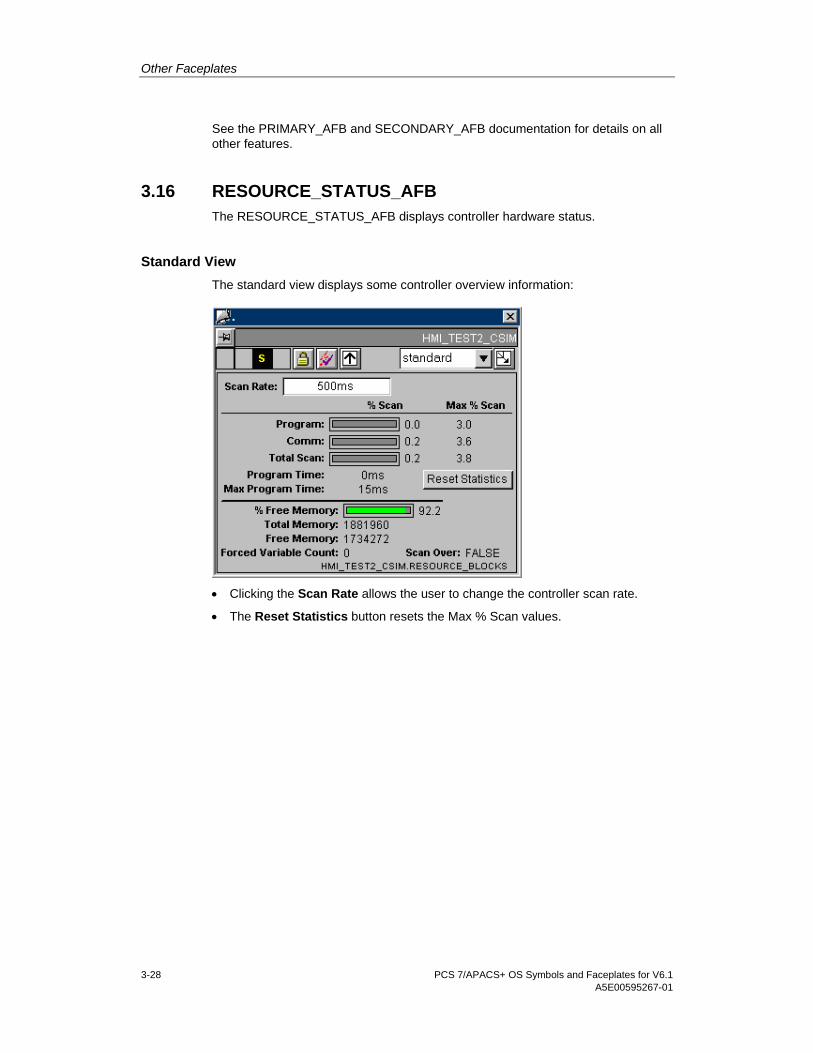
3.16 RESOURCE_STATUS_AFB The RESOURCE_STATUS_AFB displays controller hardware status.
Standard View The standard view displays some controller overview information:
• Clicking the Scan Rate allows the user to change the controller scan rate.
• The Reset Statistics button resets the Max % Scan values.

Other Faceplates
PCS 7/APACS+ OS Symbols and Faceplates for V6.1 A5E00595267-01 3-29
Embedded Variables View The embedded variables view displays controller embedded variable information:
All fields on the view are read-only.
Alarm View The Alarm view is the same view used by the SINGLE_LOOP_AFB faceplate. See the SINGLE_LOOP_AFB section for details.
Alarm Status View The alarm status view displays alarm status information:

Other Faceplates
3-30 PCS 7/APACS+ OS Symbols and Faceplates for V6.1 A5E00595267-01
• Any alarm that is active is red. Any unACKed alarm blinks.
• Clicking any button acknowledges (ACK) that alarm.
Error Log View The error log view displays error log information:
• Clicking the Details button brings up a help file containing information about the
particular controller error.
• The Next Error button allows the user to step though each controller error. The Purge Errors button deletes controller errors from the error log.
Miscellaneous View The miscellaneous view displays miscellaneous controller information:

Other Faceplates
PCS 7/APACS+ OS Symbols and Faceplates for V6.1 A5E00595267-01 3-31
All fields on the view are read-only.
Error Status A View The error status A view displays errors about the primary controller in a redundant controller architecture:
• Clicking the Details button brings up a help file containing information about the
particular controller error.
• The Manual Clear button clears the error from the controller.
Error Status B View The error status B view displays errors about the backup controller in a redundant controller architecture. It is not displayed in non-redundant architectures.

Other Faceplates
3-32 PCS 7/APACS+ OS Symbols and Faceplates for V6.1 A5E00595267-01
Clicking the Details button brings up a help file containing information about the particular controller error. The Manual Clear button clears the error from the controller.
Loop View The loop view displays all the views on one window.
Clicking the Display Alarm button toggles view three between the Alarm and Alarm Status views.

Other Faceplates
PCS 7/APACS+ OS Symbols and Faceplates for V6.1 A5E00595267-01 3-33
3.17 SINGLE_LP_SS_AFB The SINGLE_LP_SS_AFB faceplate is identical to the SINGLE_LOOP_AFB faceplate except for the addition of one binary input (SS).
The tag structure (and HMI file) has one additional tag:
Tag Type Description ACM Source
SS BIT Standby Sync .[SS]
The standard view of the faceplate has an additional SS annunciator, which is tied to the SS tag. It is not editable.
