final presentation gpii
DESCRIPTION
Casing DesignTRANSCRIPT

1
UAE University
Faculty of Engineering
Graduation project II
Casing Design in a Vertical WellFinal Presentation
Dr. MD RahmanAdvisor:
Team Members: Omar Ahmed Kamel 200100051 AbdulRahman Hasan 199900460 Ibrahim Hussain Taqi 199900628 Sultan Hussain Ahmed 200106307

2
Presentation Layout
AcknowledgementIntroductionLight Casing Design For Grade SelectionHeavy Casing Design For Grade SelectionConductor Casing DesignAPI Coupling SelectionsEconomic ConsiderationsConclusions

3
Acknowledgment
We would like to express our deepest thanks and appreciation to:
1) Prof. Reyadh Almehaideb and GP Advisor MD Rahman
2) Examiners Committee: Prof.Abdulrazq Zekri, Dr. Shedid Ali and Dr. Bilal El-Ariss
3) ADCO: represented mainly by Mr. Reymond Khairallah, S.A Turki and Adib Edris
4) Training and Graduation Projects Unit

4
Introduction
Casing is defined as a heavy large steel pipe which can be lowered into the well for the following functions:
1)Keeping the hole open by preventing the weak formations from collapsing.
2) Serving as a high strength flow conduit to surface for both drilling and production fluids.
3) Protecting the freshwater-bearing formations from contamination by drilling and production fluids.

5
Introduction
4) Providing a suitable support for wellhead equipment and blowout preventers for controlling subsurface pressure, and for the installation of tubing and subsurface equipment.
5) Providing safe passage for running wireline equipment.
6) Allowing isolated communication with selectively perforated formation(s) of interest.

6
Introduction
The main types of casing are:
1) Conductor Pipe2) Surface Casing3) Intermediate Casing4) Production Casing5) Liners
As shown in the Figure

7
Project Objectives
• To perform casing design for two vertical wells by:
1) Data collection from ADCO Company.2) Selection of casing setting depths.3) Selection of casing sizes.4) Determination of number of casings.5) Selection of casings grades and couplings.6) Economic Analysis.

8
Light Casing Setting Depth Chart
Setting Depth Chart
0
1000
2000
3000
4000
5000
6000
7000
8000
9000
10000
0 1 2 3 4 5 6 7 8 9 10 11 12 13 14 15 16
EMW (ppg)
Dept
h (f
t)
Formation PressureFracture PressureTrip Margin
Depth Objective
I ntermediate Casing Shoe
Surface Casing Shoe

9
Light Casing Program
Depth (ft.) Casing Size (in.) Casing Type
0 - 150 18-5/8 Conductor Pipe
0 - 1620 13-3/8 Surface Casing
0 - 7420 9-5/8 Intermediate Casing
7420 - 8938 7 Production Liner

10
Casing Design For Grade Selection
• Casing Design for grade selection is done based on maximum load and minimum cost.
• Collapse pressure, burst pressure and tension loads are calculated for all casings to select there suitable grades.
• Pressure testing and biaxial effects are then checked for all casings.

11
Light Surface Casing Design

12
Light Surface Casing Collapse Pressure
Depth (ft) Collapse Pressure (psi)0 0
1620 724
Collapse Pressure Vs. Depth
0
500
1000
1500
2000
0 200 400 600 800
Collapse Pressure (psi)
Dep
th (f
t)

13
Light Surface Casing Burst Pressure
Depth (ft) Burst Pressure (psi)0 815.18
1620 223.88
Burst Pressure Vs. Depth
0
400
800
1200
1600
2000
0 200 400 600 800 1000
Burst Pressure (psi)
Dep
th (f
t)

14
Light Surface Casing Grade Selection
Collapse Pressure Vs. Depth
0
400
800
1200
1600
2000
0 200 400 600 800 1000
Collapse Pressure (psi)
Dep
th (f
t)
K 55
L 80
H 40
J 55

15
Light Surface Casing Grade Selection
Burst Pressure Vs. Depth
0
400
800
1200
1600
2000
0 500 1000 1500 2000 2500 3000
Burst Pressure (psi)
Dep
th (f
t)
K 55H 40 L 80
J 55

16
Light Surface Casing Tension Calculations
Grade
DepthInterval
(ft)
GradeWeight (lb/ft)
BuoyantWeight
(1000 lbf)
CumulativeBuoyantweight
(1000 lbf)
ShockLoad(1000
lbf)
TotalTension
(1000 lbf)
YieldStrength
(1000 lbf) SF
J 55 1620 - 1480 50.3 6.03 6.03 160.96 166.99 9625.7
6
H 40 1480 - 1240 46.2 9.49 15.52 147.84 163.36 5413.3
1
L 80 1240 - 730 43.4 18.95 34.47 138.88 173.35 15568.9
8
K 55 730 - 0 36.5 22.81 57.27 116.8 174.07 9625.5
3
BFWIntervalDepthWeightBouyant n
nWLoadShock 3200
LoadShockWeightBuoyantCumulativeTensionTotal
LoadShockWeightBuoyantCumulativeTensionTotal
TensionTotalY
SF pWhere BF is Buoyancy factor, Wn is casing weight in lb/ft and Yp is the grade yield strength in lbf and SF is the safety factor.

17
Light Surface Casing Pressure Testing
• Pressure testing calculation :
• Safety factor > 1.8, so H-40 can be used.• So, all four grades are safe to be used in
the light surface casing.
67.1310)65587.685.32(
105413
3
testingpressureduringTensionTotalY
SF p
18
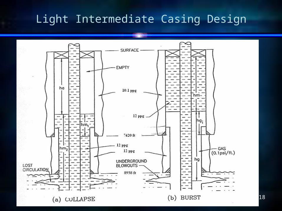
Light Intermediate Casing Design

19
Light Intermediate Casing Collapse Pressure
Depth (ft) Collapse Pressure (psi)
0 0
2277.53 1196.16
7420 688.046
Collapse Pressure Vs. Depth
0
2000
4000
6000
8000
0 500 1000 1500
Collapse Pressure (psi)
Dep
th (f
t)

20
Light Intermediate Casing Burst Pressure
Depth(ft) Burst Pressure (psi)
0 2500
5497.47 3374
7420 115.953
Burst Pressure Vs. Depth
0
2000
4000
6000
8000
0 1000 2000 3000 4000
Burst Pressure (psi)
Dep
th (f
t)

21
Light Intermediate Casing Grade Selection
Collapse Pressure Vs. Depth
0
2000
4000
6000
8000
0 500 1000 1500 2000
Collapse Pressure (psi)
Dep
th (f
t)
J 55
H 40
H 40L 80 P 110

22
Light Intermediate Casing Grade Selection
Burst Pressure Vs. Depth
0
2000
4000
6000
8000
0 2000 4000 6000
Burst Pressure (psi)
Dep
th (f
t)
P 110
L 80
H 40

23
Light Intermediate Casing Tension Calculations
GradeDepth Interval
(ft)
Grade Weight (lb/ft)
Buoyant Weight (1000
lbf)
Cumulative Buoyant weight
(1000 lbf)Shock Load (1000 lbf)
Total Tension
(1000 lbf)
Yield Strength
(1000 lbf) SF
H 40 7420 - 6250 26 26.04 26.04 83.2 109.24 295 2.70
L 80 6250 - 0 29 155.15 181.19 92.8 273.99 658 2.40
• The grades are safe to be used. • The grades are also found suitable if the
total tension load increases due to pressure testing as the safety factor is much higher than 1.8.

24
Light Casing Production Liner Collapse Pressure
Depth (ft) Collapse Pressure (psi)
6920 737.483
8938 1421.179
Collapse Pressure Vs. Depth
6000
6500
7000
7500
8000
8500
9000
9500
0 500 1000 1500
Collapse Pressure (psi)
Dep
th (f
t)

25
Light Casing Production Liner Burst Pressure
Depth (ft) Burst Pressure (psi)
6920 2311.723
8938 2118.306
Burst Pressure Calculations For Liner Design
60006500700075008000850090009500
2000 2200 2400 2600
Burst Pressure (psi)
Dep
th (f
t)

26
Light Casing Production Liner Tension Calculations
GradeDepth
Interval (ft)
Grade Weight (lb/ft)
BuoyantWeight
(1000 lbf)
Cumulative Buoyant Weight
(1000 lbf)
Shock Load
(1000 lbf)
Total Tension (1000 lbf)
Yield Strength (1000 lbf) SF
J 55 8938 – 7850 16.2 15.09 15.09 51.84 66.93 258 3.85
H 40 7850 – 6920 14.8 11.78 26.87 47.36 74.23 171 2.30
• Both grades are safe for use. • Here, also by calculating the additional
tension due to pressure testing it is found that the safety factor > 1.8.

27
Heavy Casing Setting Depth Chart
Setting Depth Chart
0
1000
2000
3000
4000
5000
6000
7000
8000
9000
10000
0 1 2 3 4 5 6 7 8 9 10 11 12 13 14 15
EMW (ppg)De
pth
(ft)
Fracture PressureFormation PressureTrip Margin
Surface Casing Shoe
1st I nermediate Casing Shoe
2nd I ntermediate Casing Shoe Depth Objective

28
Heavy Casing Program
Depth Casing Size (in) Casing Type
0 - 150 30 Conductor Pipe
0 - 1610 18-5/8 Surface Casing
0 - 5800 13-3/8 Intermediate Casing
0 - 9420 9-5/8 Intermediate Casing
9420 - 9532 7 Production Liner
29
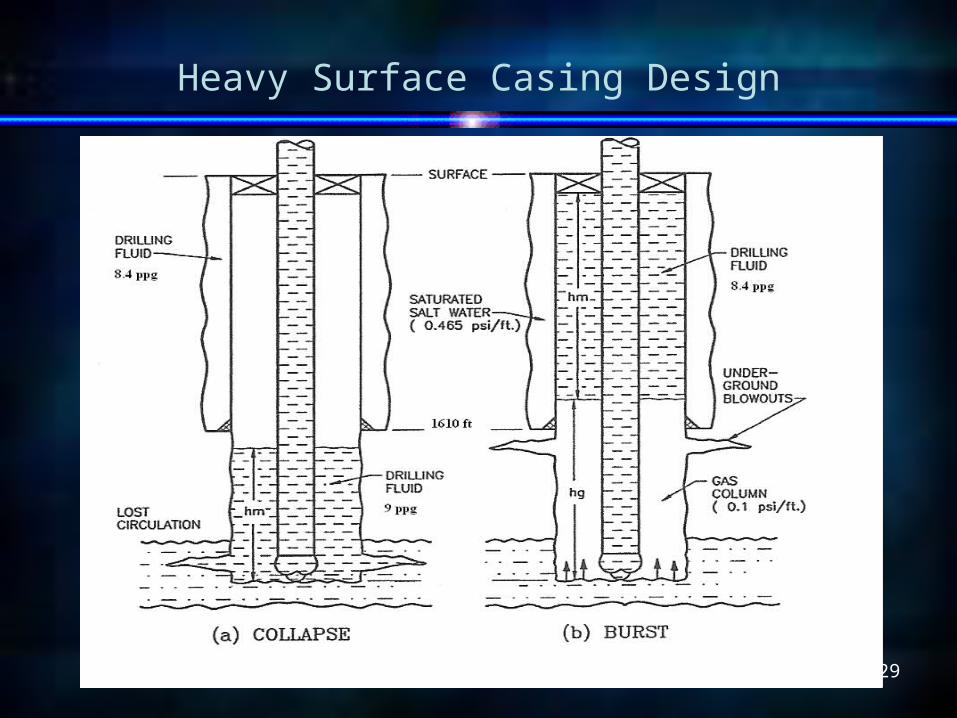
Heavy Surface Casing Design
30
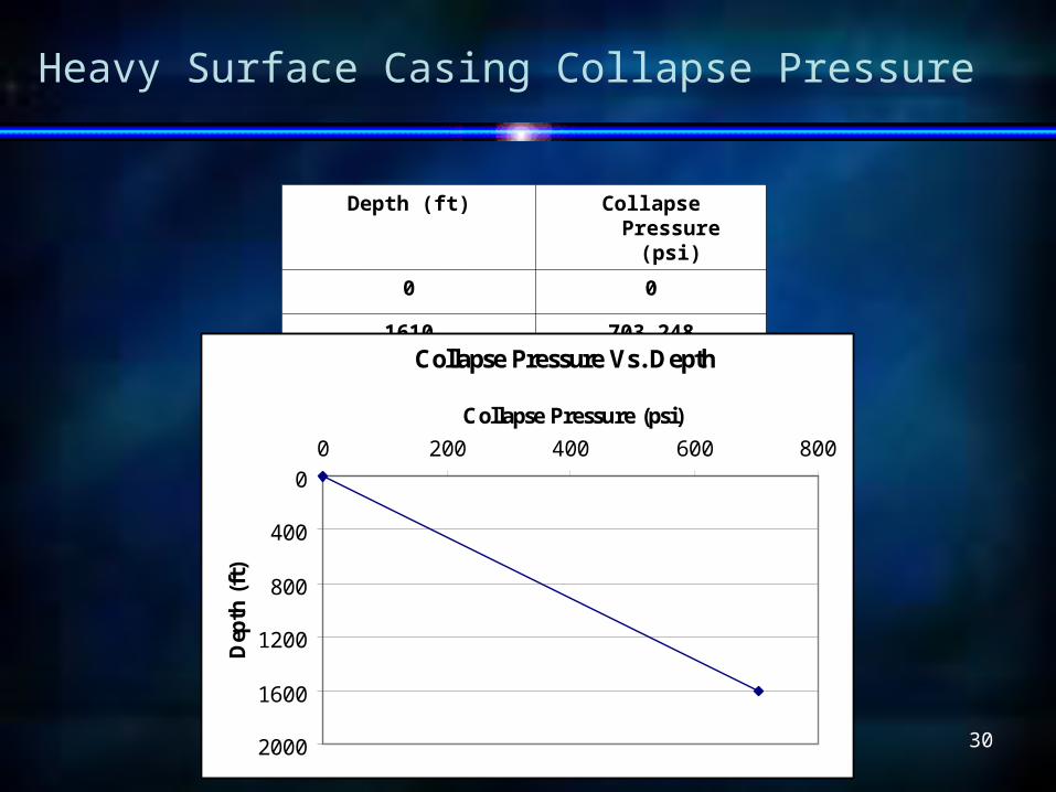
Heavy Surface Casing Collapse Pressure
Depth (ft) Collapse Pressure (psi)
0 0
1610 703.248
Collapse Pressure Vs. Depth
0
400
800
1200
1600
2000
0 200 400 600 800Collapse Pressure (psi)
Dep
th (f
t)

31
Heavy Surface Casing Burst Pressure
Depth (ft) Burst Pressure (psi)
0 718.06
1610 130.41
Burst Pressure Vs. Depth
0
400
800
1200
1600
2000
0 200 400 600 800
Burst Pressure (psi)
Dep
th (f
t)

32
Heavy Surface Casing Grade Selection
Collapse Pressure Vs. Depth
0
400
800
1200
1600
2000
0 200 400 600 800Collapse Pressure (psi)
Dep
th (f
t)
H 4
0
H 40 J 55
J 55 K 5
5
GradeWeight (lb/ft)
Collapse Resistance
(psi)Depth
Intervals (ft)
H 40 70.6 320 0 – 780
J 55 82.2 520 780 - 1200
K 55 93.6 790 1200 - 1610

33
Heavy Surface Casing Grade Selection
• All the Grades are suitable for the Burst Pressure.
Burst Pressure Vs. Depth
0
400
800
1200
1600
2000
0 500 1000 1500 2000 2500
Burst Pressure (psi)
Dep
th (f
t)
H 4
0
J 55
K 5
5

34
Heavy Surface Casing Tension Calculations
GradeDepth
Interval (ft)
Grade Weight (lb/ft)
Buoyant Weight
(1000 lbf)
Cumulative Buoyant
weight (lbf/ft)
Shock Load
(1000 lbf)
Total Tension (1000 lbf)
Yield Strength (1000 lbf) SF
K 55 1610 - 1200 93.6 32.85 32.85 299.52 332.37 1474 4.43
J 551200 - 780 82.2 29.55 62.40 263.04 325.44 1290 3.96
H 40780 - 0 70.6 47.14 109.54 225.92 335.46 804 2.40
35
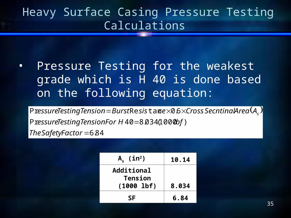
Heavy Surface Casing Pressure Testing Calculations
• Pressure Testing for the weakest grade which is H 40 is done based on the following equation:
84.6)1000(034.840Pr
6.0tanRePr
FactorSafetyThelbfHForTensionTestingessure
AAreaSecntinalCrosscesisBurstTensionTestingessure s
As (in2) 10.14
Additional Tension (1000 lbf) 8.034
SF 6.84

36
Heavy Surface Casing Design Biaxial Calculations
Biaxial effect:
Where: σa is the axial stress due to tension (psi σy is minimum yield strength of the grade (psi) Ypa is the effect yield strength (psi) do is the outer casing diameter (in) di in the inner casing diameter (in)
y
a
y
ayp
io
a
Y
dd
GradeWeakestByCarriedWeightBouyant
o
5.075.01
45.0
22

37
Heavy Surface Casing Design Biaxial Calculations
• Biaxial effect is calculated using the following set of equations:
Where: A,B, C, F and G are empirical constants
31327
6
3162105
1036989.01010483.0030867.093.465
1050609.0026233.0
1053132.01021301.01010679.08762.2
papapa
pa
papapa
YYYC
YB
YYYA
ABFG
ABABAB
ABABY
ABAB
F
pa
/)(
/2/31/
/2/3
/2/31095.46
2
36

38
Heavy Surface Casing Design Biaxial Calculations
σa 2913.47
σy 40000
Yp 38463.61
do/t 53.21429
• The biaxial results for heavy surface casing:
Stress Calculations Coefficients Calculations
A 2.945766
B 0.045699
C 707.922
F 2.078155
G 0.032239

39
Heavy Surface Casing Design Biaxial Calculations
do/t >Model
53.2142857 > 43.30674 Elastic
• From the results:
• The collapse pressure remain unchanged (Elastic Model)
ABABtdo /3
/2/
ABAB
/3/2
Where dWhere doo is the outer casing diameter, in is the outer casing diameter, in t is the thickness of casing, in t is the thickness of casing, in

40
1st Heavy Intermediate Casing Design

41
1st Heavy Intermediate Casing Collapse Pressure
Depth (ft) Collapse Pressure (psi)
0 0
5800 2714.4
Collapse Pressure Vs. Depth
0
1000
2000
3000
4000
5000
6000
0 500 1000 1500 2000 2500 3000
Collapse Pressure (psi)
Dep
th (f
t)

42
1st Heavy Intermediate Casing Burst Pressure
Depth (ft) Burst Pressure (psi)
0 5931.28
5800 3814.28
Burst Pressure Vs. Depth
0
1000
2000
3000
4000
5000
6000
7000
0 1000 2000 3000 4000 5000 6000 7000
Pressure (psi)
Dep
th (f
t)

43
1st Heavy Intermediate Casing Tension Calculations
• Selected grades based on collapse and burst pressures and Tension Calculation:
• The selected grades are safe and meet all the loads
Grade
Grade Weight (lb/ft)
Buoyant Weight
(1000 lbf)
Cumulative Buoyant
weight (1000 lbf)
Shock Load
(1000 lbf)
Total Tension
(1000 lbf)
Yield Strength (1000 lbf) SF
P 110 73.1 81.35 81.35 233.92 315.27 1225 3.89
L 80 65.2 251.15 332.50 208.64 541.14 1452 2.68

44
2nd Heavy Intermediate Casing Design

45
2nd Heavy Intermediate Casing Collapse Pressure
Depth (ft) Collapse Pressure (psi)
0 0
3074.57 1838.59
9420 1277.66
Collapse Pressure Vs. Depth
0
2000
4000
6000
8000
10000
0 500 1000 1500 2000
Collapse Pressure (psi)
Dep
th (f
t)

46
2nd Heavy Intermediate Casing Burst Pressure
Depth (ft) Burst Pressure (psi)
0 2500
6705.64 3984.63
9420 2993.89
Burst Pressure Vs. Depth
0
2000
4000
6000
8000
10000
0 1000 2000 3000 4000 5000
Burst Pressure (psi)
Dep
th (f
t)

47
2nd Heavy Intermediate Casing Grade Selection
Collapse Pressure Vs. Depth
0
2000
4000
6000
8000
10000
0 500 1000 1500 2000
Collapse Pressure (psi)
Dep
th (f
t)
C75
33.
9 lb
/ftC 75 32lb/ft
C 75 32lb/ft

48
2nd Heavy Intermediate Casing Grade Selection
Burst Pressure Vs. Depth
0
2000
4000
6000
8000
10000
0 1000 2000 3000 4000 5000
Burst Pressure (psi)
Dep
th (f
t)
C75
33.
9 lb
/ft
C 75 32lb/ft
C 75 32lb/ft

49
2nd Heavy Intermediate Casing Tension Calculations
GradeDepth
Interval (ft)
Grade Weight (lb/ft)
Buoyant Weight
(1000 lbf)
Cumulative Buoyant weight
(1000 lb/ft)
Shock Load
(1000 lbf)
Total Tension
(1000 lbf)
Yield Strength(1000 lbf) SF
C 75 9420 - 7250 32 59.44 59.44 102.4 161.84 559 3.45
C 75 7250 - 2700 33.9 132.03 191.47 108.48 299.95 680 2.27
C 75 2700 - 0 32 73.96 265.43 102.4 367.83 559 1.52
L 80 2700 - 0 33.9 78.35 265.43 108.48 373.91 771 2.06
• Grade C 75 of weight 32 lb/ft doesn’t satisfy tension load requirements so it is replaced with grade L 80 of weight 33.9 lb/ft.
• Pressure testing and biaxial loads will not cause any change in the selected grades.

50
Heavy Casing Production Liner Collapse Pressure
Depth (ft) Collapse Pressure (psi)
9032 1311.96
9532 1267.75
Collapse Pressure Vs. Depth
9000
9200
9400
9600
1200 1250 1300 1350
Collapse Pressure (psi)
Dep
th (f
t)

51
Heavy Casing Production Liner Burst Pressure
Depth (ft) Burst Pressure (psi)
9032 3135.96
9532 2953.01
Burst Pressure Vs. Depth
9000
9200
9400
9600
2800 2900 3000 3100 3200 3300 3400
Burst Pressure (psi)
Dep
th (f
t)

52
Heavy Casing Production Liner Grade Selection
Collapse Pressure Vs. Depth
9000
9200
9400
9600
1200 1250 1300 1350
Collapse Pressure (psi)
Dep
th (f
t) C 75
L 8
0
Burst Pressure Vs. Depth
9000
9200
9400
9600
2900 3100 3300 3500 3700 3900
Burst Pressure (psi)
Dep
th (f
t)
C 75 L 80

53
Heavy Casing Production Liner Grade Selection
GradeDepth Interval
(ft)
Grade Weight (lb/ft)
Buoyant Weight
(1000 lbf)
Cumulative Buoyant
weight (1000 lbf)
Shock Load
(1000 lbf)
Total Tension
(1000 lbf)
Yield Strength
(1000 lbf) SF
L 80 9532 - 9250 15.5 3.74 3.74 49.6 53.34 358 6.71
C 75 9250 - 9032 15.3 2.86 6.60 48.96 55.56 331 5.96
• Both grades are safe for production liner

54
Conductor Casing Design
• The conductor casing is set at 150 ft for both light and heavy casing designs.
• Usually the conductor casing is driven for such shallow depth and this is also practiced in ADCO
• Conductor size is 18-5/8 in. for light casing and 30 in. for heavy casing.
• J-55 and X-65 grades have been selected finally for conductor pipe for light and heavy casing designs respectively.

55
API Coupling Selections
• Round short and long thread couplings are mostly used in the casing design.
• The same couplings are considered in both light and heavy casing designs.
• There strengths for each grade for all the casings designed so far are compared with the respective total tension load and it is found that the safety factor is higher than 1.8

56
Economic Considerations
Design Features Cost $ Savings
Single grade 721500 143142 $
Combination grades 578358 20%
Light Casing Design Cost Analysis
Heavy Casing Design Cost Analysis
Design Features Cost $ Savings
Single grade 283584 27850 $
Combination grades 255734 10%

57
Conclusions
• Collapse, burst, tension and biaxial design principles are studied carefully to apply graphical methods for casing grade selection.
• Maximum load design principles and worst loading conditions are applied for both casing designs successfully, and combination grades are selected for each casing string satisfying all constraints and meeting all loads.
• Cost analyses are performed for each casing design.
• Environmental considerations are given emphasis in both casing designs.

58