final project progress report - california department of … · 2009-09-22 · final project...
TRANSCRIPT
Page I of 39
EVALUATION OF COMMERCIAL VIDEO-BASED INTERSECTION SIGNAL ACTUATION SYSTEMS
Final Project Progress Report
Prepared for the California Department of Transportation, Division of Research and Innovation
Principal Investigator: C. Arthur MacCarley, Ph.D., PE.,
Professor and Chair, Electrical Engineering Department, California Polytechnic State University, San Luis Obispo via the Cal Poly Corporation
Project Manager: Joseph Palen, Caltrans Division of Research and Innovation
Caltrans Agreement Number 65A0199, Cal Poly Corp Project No. 49492
Document No. CP-VIDE-FR-01
December 30, 2008
Page I of 39
Glossary of Acronyms and Special Terms DRI Caltrans Division of Innovation and Research
Mean Arithmetic average of a set of variables, or estimate of expected value of a sample set
MPH Miles per Hour
MOE Metric (or Measure) of Effectiveness
Standard Deviation A statistic indicative of the spread of data about the mean value
TMC Traffic Management Center
TMS Traffic Management System
VTDS Video Traffic Detection System
Keywords California Department of Transportation (Caltrans), Division of Innovation and Research, Video Traffic Detection, Intersection Detectors, VTDS, VIPS, ITS, Iteris, Autoscope, MediaCity, Trafficon, Citilog, Quixote, Peek, Eagle Traffic, Videotrak.
Cal Poly SLO and Caltrans Division of Innovation and Research
Page 2
Project Summary Video cameras and computer image processors have come into widespread use for the detection of vehicles for signal actuation at controlled intersections. Video is considered both a cost-saving and convenient alternative to conventional stop-line inductive loop detectors. Manufacturers’ specification and performance statements vary in the metrics used and data reported, and are inconsistent between available products. The lack of common test standards and procedures has made product selection and optimal deployment decisions difficult for local jurisdictions as well as Caltrans. Performance of these systems is difficult to ascertain by simple observation of signal actuation.
The project builds upon work conducted under the 1995-97 PATH-sponsored Video Traffic Detection System Evaluationa, in which in consultation with an extensive advisory board including the FHWA, Caltrans, City traffic personnel and system manufacturers, a standardized approach for the evaluation of intersection detection systems was developed and applied to one such system deployed as part of a FHWA Field Operational Test.
The present evaluation updates and applies these standards and procedures to the testing and comparative evaluation of examples of video-based intersection signal actuation systems in general. Over a two-year period, standardized test methodologies and metrics of effectiveness (MOEs) were developed in consultation with current and potential users of these systems, system manufacturers, and colleagues at other institutions that had performed related evaluations. Technical background and product update reviews were completed multiple times during the nearly three year extended project period as technologies changed. Many lessons were learned during this process. The project as proposed required the volunteer cooperation of both the system manufacturers and traffic management agencies that deploy theses systems. Unfortunately, no funding was available for the purchase of systems for testing or the reimbursement of costs associated with deployment work by local agencies, which was required to conform with local traffic safety concerns and labor restrictions. While we had intended to be able to report independent comprehensive performance data based upon the test procedures developed in the course of this work, from at least a subset of the commercially available systems, this was ultimately not possible due to a lack of volunteer cooperation and test restrictions later raised by all except one system manufacturer. Product “warranty concerns” were also raised by the vendor of the systems that were already deployed at our local designated test intersections. Regardless, the information and lessons learned over the course of this effort provide improved insight into both the advantages and limitations of this class of detectors. The actual evaluation project remains an on-going effort by Cal Poly, regardless of funding. Sufficient hardware and protocol development effort in support of the final testing of the commercial systems has been completed, and will result in published system test data as negotiations continue and we succeed in obtaining the use of system for testing purposes from alternative sources. Background Basic research on computer vision techniques for traffic detection dates back to the mid-late 1980’s. Many products have been developed, some significantly deployed, and a subset of these considered commercially successful. Data on the accuracy and/or effectiveness of these systems has largely been self-reported by manufacturers, using a variety of different metrics and rarely revealing limitations. Only a limited number of external evaluations have been performed containing adequate technical depth. This has been especially true of intersection detection products intended for traffic signal actuation. Interest in and deployment of these systems is growing, and there is an increasing need for objective test protocols and metrics of performance to facilitate the comparison and selection of systems for deployment. Key evaluation works related to computer vision systems for traffic monitoring or detection are summarized below.
a Executive summary at http://www.path.berkeley.edu/PATH/Research/Featured/1298/Default.htm
Cal Poly SLO and Caltrans Division of Innovation and Research
Page 3
An early evaluation project was conducted by Hoose in 1990, in the context of a survey of techniques and new technologies for possible deployment on Australian highways.1 A broad evaluation of video cameras as sensors for highway surveillance and monitoring was performed by MacCarley for the California Department of Transportation, 1991-93. 2 3 First generation computer vision systems for measurement of traffic flow metrics were evaluated by MacCarley and others at Cal Poly 1992 through 1995 4 5. A similar study was performed by Klein at Hughes Electronics 1993-956 for the US Department of Transportation, FHWA. A comprehensive evaluation of non-visible spectrum imagers for traffic detection was studied by Klein 7 in 1995, and MacCarley and Ponce8 9, 1994 through 1999. During 1997-99, an evaluation of non-intrusive sensors for monitoring traffic was conducted by SRF and Associates10 for the Minnesota Department of Transportation.
The introduction of computer vision methods for intersection signal actuation in the early 1990’s lead to a number of initial deployments, usually trial installations or field operational tests. While the literature is dense with publications by manufacturers of products and theoretical advances in computer vision algorithms, there has been little effort devoted to the detailed and comprehensive examination of the actual performance of these systems. The first external objective analysis of this type of system, which established appropriate metrics of performance and comprehensive test procedures, was conducted by MacCarley at Cal Poly SLO 1995-98 funded via PATH by the FHWA, through a field operational test in Anaheim, CA. 11 12 13 Among the few other published evaluations of deployed systems was a study conducted by Jutaek in 200314, in which one such system was evaluated prior to possible deployment.
Recent ancillary works which include some element of evaluation of video image processing methods for traffic applications include the work of Bahler in 199815, Kastrinaki in 200316, and PATH researchers Malik and Stewart at UC Berkeley. During 2003-present, Bullock and Sturdevant at Purdue University are evaluating video traffic detection systems on an Instrumented Intersection in Noblesville, IN17
In general, video cameras and computer image processors have come into widespread use for both traffic monitoring and the detection of vehicles for signal actuation at controlled intersections. In the latter application, video detectors are considered direct replacements for in-ground sensing methods, typically inductive loops. Among the advantages of video-based detectors are ease of installation, requiring no pavement work, and the possibility of temporarily deployment when conventional detection is inoperative, such as during construction. Once integrated with the signal controller, these systems become critical sensors, affecting traffic flow efficiency to a possibly significant degree. This is especially true when the sensors drive an adaptive intersection control strategy such as SCOOT10 11 (Split, Cycle and Offset Optimization Technique), which usually relies upon mid-block detectors, as well as stop line and queue length detectors to perform anticipatory optimization.
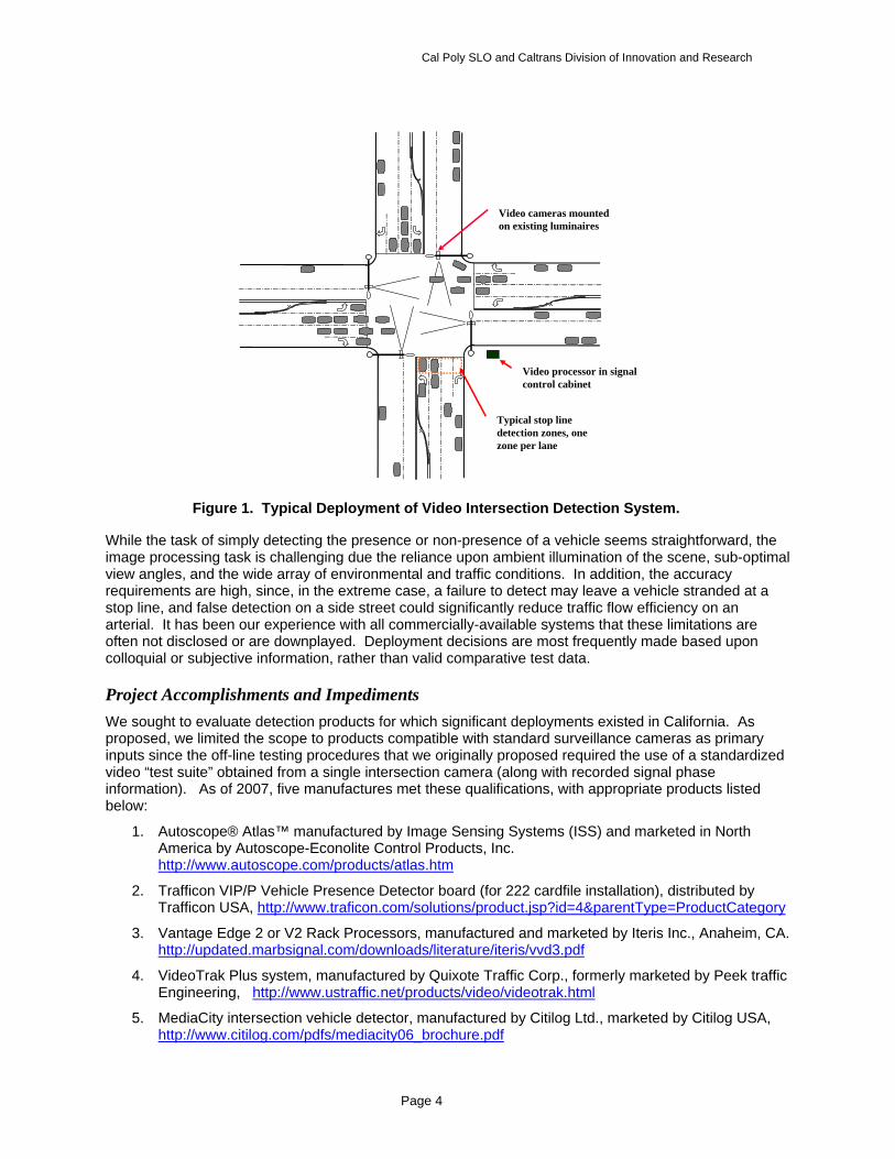
A typical deployment of a stop-line intersection detection system is illustrated in Figure 1. A photograph of a candidate intersection detection product appears in Figure 2.
Cal Poly SLO and Caltrans Division of Innovation and Research
Page 4
While the task of simply detecting the presence or non-presence of a vehicle seems straightforward, the image processing task is challenging due the reliance upon ambient illumination of the scene, sub-optimal view angles, and the wide array of environmental and traffic conditions. In addition, the accuracy requirements are high, since, in the extreme case, a failure to detect may leave a vehicle stranded at a stop line, and false detection on a side street could significantly reduce traffic flow efficiency on an arterial. It has been our experience with all commercially-available systems that these limitations are often not disclosed or are downplayed. Deployment decisions are most frequently made based upon colloquial or subjective information, rather than valid comparative test data.
Project Accomplishments and Impediments We sought to evaluate detection products for which significant deployments existed in California. As proposed, we limited the scope to products compatible with standard surveillance cameras as primary inputs since the off-line testing procedures that we originally proposed required the use of a standardized video “test suite” obtained from a single intersection camera (along with recorded signal phase information). As of 2007, five manufactures met these qualifications, with appropriate products listed below:
1. Autoscope® Atlas™ manufactured by Image Sensing Systems (ISS) and marketed in North America by Autoscope-Econolite Control Products, Inc. http://www.autoscope.com/products/atlas.htm
2. Trafficon VIP/P Vehicle Presence Detector board (for 222 cardfile installation), distributed by Trafficon USA, http://www.traficon.com/solutions/product.jsp?id=4&parentType=ProductCategory
3. Vantage Edge 2 or V2 Rack Processors, manufactured and marketed by Iteris Inc., Anaheim, CA. http://updated.marbsignal.com/downloads/literature/iteris/vvd3.pdf
4. VideoTrak Plus system, manufactured by Quixote Traffic Corp., formerly marketed by Peek traffic Engineering, http://www.ustraffic.net/products/video/videotrak.html
5. MediaCity intersection vehicle detector, manufactured by Citilog Ltd., marketed by Citilog USA, http://www.citilog.com/pdfs/mediacity06_brochure.pdf
Video processor in signalcontrol cabinet
Typical stop linedetection zones, onezone per lane
Video cameras mountedon existing luminaires
Figure 1. Typical Deployment of Video Intersection Detection System.

Cal Poly SLO and Caltrans Division of Innovation and Research
Page 5
At the time of the proposal, all the vendors listed above advertised at least one version of their product(s) that was/were capable of utilizing the output of a standard surveillance camera, positioned appropriately at an intersection. The obvious advantage of such a feature is that the installed camera may be used for remote intersection monitoring as well as signal actuation. In the proposed and initially-approved test method, full-motion video and digitally encoded signal phase information were to be recorded from existing camera feeds and signal controllers at selected test intersections. Test protocols and performance metrics were to be developed consistent with this capability, which allowed the creation of a common recorded video “test suite”, including digitally-encoded signal phase information, which could be used to test all systems under identical conditions. If inductive loops are present at a test intersection, the outputs of these would also be digitally recorded in synch with the video data, for comparison testing with the video systems.
Building upon prior work 13 a comprehensive test methodology and comprehensive Measures of Effectiveness (MOEs) were developed based upon the “Test Suite” approach. This approach is believed to be the best approach for assuring absolute consistency of test conditions and video feed quality for all systems under test. The results of this work, including the array of testable conditions that would comprise the video test suite and a canonical set of MOEs, are described in the later section Test Methologies.
The development of this test suite evolved over a twelve-month period in consultation with the five system vendors, each to degrees varying from lack of comments to significant and helpful advice. At the culmination of this effort, all evaluation procedures and candidate system selections were reviewed and approved by Caltrans technical personnel prior to implementation.
Implementation of testing then proceeded with the contacting of traffic management jurisdictions that operated intersection video detection systems on their respective rights-of-way:
1. Caltrans District 5 (San Luis Obispo)
2. City of San Luis Obispo, Traffic Engineering Division of Department of Public Works.
3. City of Anaheim, Traffic Engineering Department (site of previous evaluation work by the PI)
In brief, the Caltrans local district (D5) was found to not operate video intersection detection systems on their limited surface streets rights-of-way, typically on overcrossings on US 101 through the City of San Luis Obispo. Only one such intersection under D5 jurisdiction utilized this type of detection equipment, and it was managed by the City of San Luis Obispo as part of their network of controlled locations.
At the start of this project (2005), the City of San Luis Obispo had not yet deployed video-based intersection detection equipment. However, by 2008, the City had video intersection detection equipment deployed at over 25 intersection, all equipment sourced by Vendor 3 (Iteris).
Because of the lack of local test facilities early in the project, the PI reestablished contacts with the City of Anaheim Traffic Engineering Department. Anaheim has extensive deployments of detectors sourced by Vendors 1 and 3. John Thai, Traffic Engineer for the City of Anaheim, offered his cooperation. Negotiations were begun to allow testing under our study at selected intersections in Anaheim.
Two full-frame-rate four channel digital video recorders (DVRs) were purchased and equipped with interface circuits of our own design to encode signal phase and loop output data in the video blanking intervals for reconstruction during playback. These would be used to acquire raw video feeds from the luminaire-mounted NTSC video cameras located at selected test intersections.
Creation of the video test suite was to proceed following arrangements for the loan of the compatible models of each video processor. Over a period of 24 months we corresponded and met with each vendor in an effort to solicit the loan or a test system, and tech support during testing. Manufacturers changed ownership with both consolidations and spin-offs. A final list of systems (as 2008) including all contact information is provided in Appendix A.
The evaluation test plan was revised multiple times to accommodate restrictions imposed by system manufacturers. Ultimately, manufacturers 1 through 4 insisted, contrary to the requirements of the approved test plan, that only video cameras manufactured or resold by them could be used as video sources for their processors, and that only intersections set up and approved by them could be used for
Cal Poly SLO and Caltrans Division of Innovation and Research
Page 6
test purposes. Technical arguments were based upon the need for optimal system deployments, or the preference that only product versions which used fully-integrated cameras (one including computer control of the iris) would truly represent the capabilities of the best of their product lines. These restrictions precluded the use of a standardized video test suite for identical product performance comparisons. This fundamentally changed the proposed test methodology, and required that we develop multiple alternative plans to meet the requirements of each system manufacturer, while still providing results that were at least marginally comparable. Two test method options were identified:
1. Test each candidate system at different intersections, selected, set up and approved by each of the detection system manufacturers. This approach assures that the system manufacturers have endorsed the installation and locations. However, it prevents the direct comparison of results between different systems since testing would occur using different traffic streams and under different environmental and illumination conditions.
2. Install all systems on the same approaches at the same intersection, with cameras positioned as closely together as possible. Run tests concurrently, with either no system of only one system actually actuating the signal. This requires that the camera mounting structure, typically a luminaire mast arm, be of sufficient strength to support multiple cameras in addition to the luminaire head. All except one camera would be positioned suboptimally. Since only one system would actually control the signal, some concerns about optimality of the operational conditions for each system would be possible. And most significant for the study, each system would have to loaned or purchased, installed and “tuned” by the manufacturer at the expense of the project, which was not budgeted.
Only the latter alternative method would produce data that would allow direct performance comparisons between systems. Of these two available options at this late date in the project (March 2008), we therefore elected to proceed in any way possible with Option two. After site inspections and negotiation with the Traffic Engineering Division of the San Luis Obispo Department of Public Works, five possible evaluation test sites were made available to us by the City of San Luis Obispo Division of Traffic Engineering:
1. California St. and Foothill Blvd.
2. Los Osos Valley Road and Royal Way
3. Los Osos Valley Road and Madonna Road
4. Los Osos Valley Road and Calle Joaquin
5. Los Osos Valley Road and Froom Ranch Road
All intersections were already equipped with Iteris Vantage® (Vendor 3) video detection systems. Only Site 1 was equipped with inductive loop detectors, which had been disconnected, but were still operational according to our loop inductance measurements. Site 1 had video detection on three of the four approaches, and was proximate to the Cal Poly campus. It was one of the first intersection in the City of San Luis Obispo to be equipped with video detection, and as such, was equipped with an older (2005) Iteris Vantage detection system that used a monochrome camera which was not considered by a vendor to be acceptable for comparative testing purposes, but would not be upgraded. Site 2 was not equipped with video detection, but had the advantage of being sufficiently proximate to the Cal Poly campus to permit line-of-site wireless communications of video signals, which could be processed in our laboratory. Site 3 had video detection on all four approaches. It was a high-traffic site with two through lanes, one interior bike lane, and designated right and left turn lanes. Site 4 was actually located on Caltrans right-of-way at the base of an overcrossing over US 101. It had video detection on three approaches, but access to the controller cabinets was difficult due to the unusual intersection configuration. Site 5 was a high-traffic location that had the advantage of a real-time full-frame-rate video feed to the Traffic Management Center in downtown San Luis Obispo. However, the Iteris installation at this location used an “experimental high resolution camera” that was considered proprietary by the vendor. We were not permitted access to the camera or system at this location.
Cal Poly SLO and Caltrans Division of Innovation and Research
Page 7
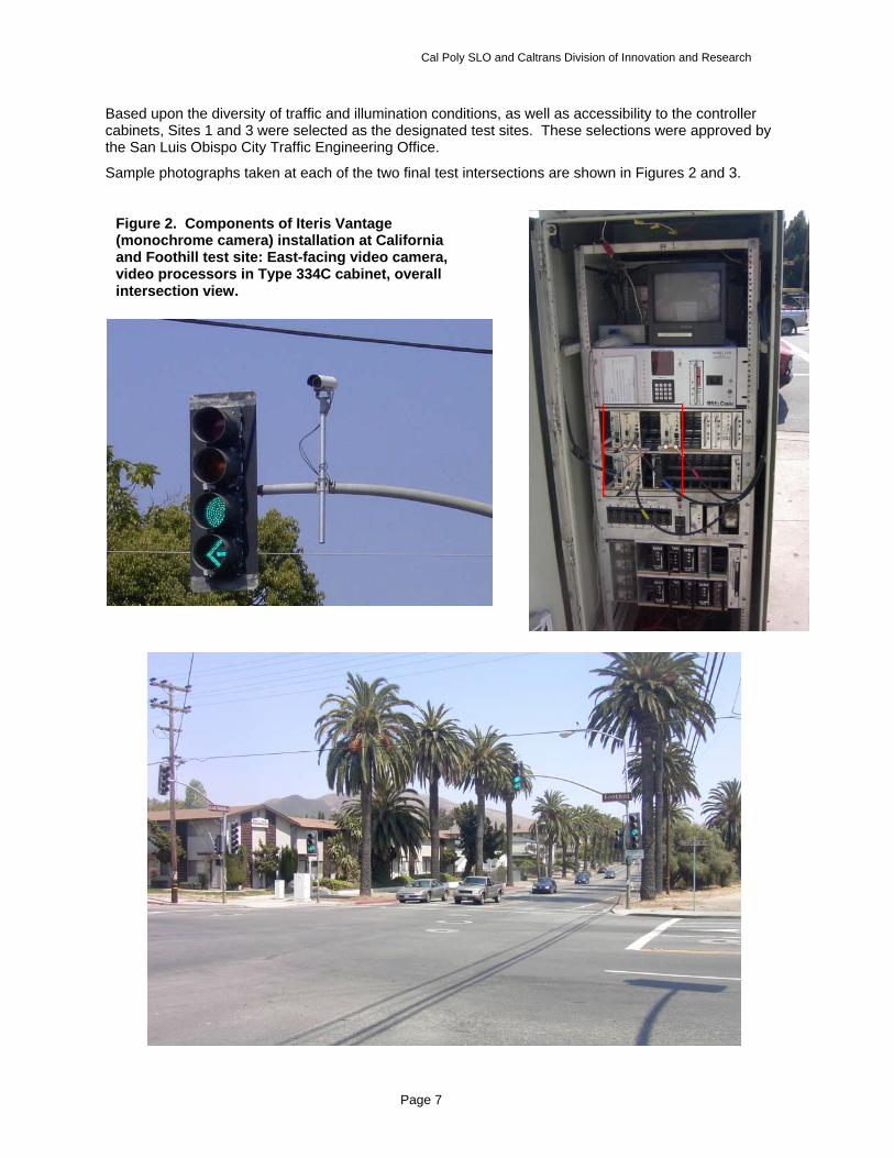
Based upon the diversity of traffic and illumination conditions, as well as accessibility to the controller cabinets, Sites 1 and 3 were selected as the designated test sites. These selections were approved by the San Luis Obispo City Traffic Engineering Office.
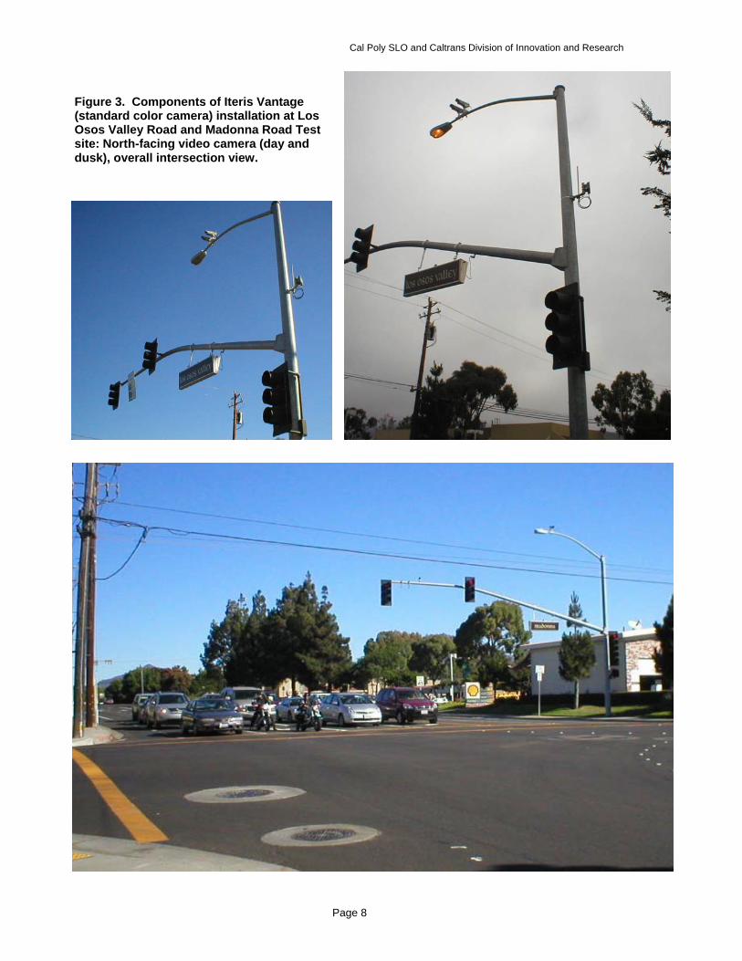
Sample photographs taken at each of the two final test intersections are shown in Figures 2 and 3.
Figure 2. Components of Iteris Vantage (monochrome camera) installation at California and Foothill test site: East-facing video camera, video processors in Type 334C cabinet, overall intersection view.
Cal Poly SLO and Caltrans Division of Innovation and Research
Page 8
Figure 3. Components of Iteris Vantage (standard color camera) installation at Los Osos Valley Road and Madonna Road Test site: North-facing video camera (day and dusk), overall intersection view.
Cal Poly SLO and Caltrans Division of Innovation and Research
Page 9
Negotiations continued with each system vendor in an effort to secure the loan of systems for testing, and technical supervision of the system setup and configuration. A meeting with manufacturers’ representatives and management personnel, and the City of San Luis Obispo traffic engineer, was held in conjunction with the ITE Exhibition in Anaheim, August 17, 2008. Considerable email and telephone correspondence followed. By September 2008, the City of San Luis Obispo reported to us that “warranty issues” had been raised by Vendor 3 (Iteris) that would prevent the City from loaning us their spare video camera, or allowing us from making any electronic measurements of the video output of the system camera. Vendor 1 refused to support or participate in the testing of any of their systems. After initial successful discussions with Vendors 2 and 4, subsequent communications with management were not returned, although if a full purchase and paid installation were possible under this project, we believe they would have been receptive. Only Vendor 5 (Citilog) offered full cooperation with the loan and support of a test system. Further, only this vendor allowed testing of their system using a standard NTSC video feed from a general video camera not sold by them, consistent with the approved test methodology. It should be noted, however, that Citilog does not currently have any deployments of the MediaCity system in California.
The cost of installations also became an issue if we were to use Alterative Test Method 2 (multiple systems tested concurrently on the same approach at the same site). The City of San Luis Obispo was not in a position to provide a bucket truck or personnel for the installation of the system cameras at the test intersections, and concerns were raised about the safety of the installation of multiple cameras on a single luminaire arm. Our investigation of the load bearing specifications for these structures indicated no problems, but liability concerns were not diminished, and the setup of more than two cameras (previously done by the vendor) on a luminaire arm was not authorized.
By October 31, 2008, after extensive correspondence and negotiations, it became clear that the generation of comparative system test results would not be possible in the context of the project as proposed, and this was reported to the Caltrans Project Monitor, who had been kept informed throughout the events of the project. Remaining effort was to be directed toward keeping open the option to complete the intended comparison tests at the selected test sites in continued post-contract work or under a possible future study, documentation of test protocols and MOEs developed in the course of this work, as well as alternatives acceptable to at least some system vendors, and reporting of experiences gained in this process. A key lesson learned was that no study could be conducted which relied upon the volunteer cooperation of system vendors or facility providers – the assumptions of the proposed study had been over-optimistic.
Chronology of Key Project Events 1/15/2004 Pre-proposal submitted: PATH RFP: 2004-2005, Applicable research problem statements: XB08: Portable, Field-Deployable Traffic Detection System and TS09: Measure and field test the Effectiveness of Adaptive Traffic Control for Arterial Management
3/11/2004 Proposal submitted to PATH for 2004-2005 solicitation, Topic area XB08-B, (Portable Field-Deployable Traffic Detection System). Performance period specified to be July 1, 2004 – June 30, 2005.
3/3/2005 Draft contract issued by Caltrans Division of Procurement and Contracts
6/21/2005 Contract approved by Cal Poly Corporation, performance period specified to be June 30, 2005 to December 30, 2006.
9/1/2005 Actual project start date due to prior research obligations of PI and inability to hire student research assistants after the start of the summer.
9/1/2005 – 12/31/2005 Background and product research, extensive correspondence, meetings, discussions with vendors regarding proposed test methodology and procedures.
10/31/05 Project Progress Report 1. Report on prior research, current products, vendors, and contacts delivered to Caltrans.

Cal Poly SLO and Caltrans Division of Innovation and Research
Page 10
11/22/2005 Caltrans endorsement of official contact letter for participation of product vendors in video traffic detection test.
1/5/2006 Comprehensive report on prior research and evaluation results delivered to Caltrans. Draft Video Detection System Evaluation Method document delivered to Caltrans for comments/approval, following extensive consultation with vendors, including many vendor-requested modifications.
1/12/2007 Collaboration and data-sharing agreement reached with Prof. Darcy Bullock of Purdue University.
1/31/2006 Caltrans approves Intersection Video Detection Evaluation Method document.
2/1/2006 – 6/30/2007 Correspondence, meetings, negotiations with system vendors and potential test site operators (summarized in text).
7/1/2006 Meeting and visit by John Thai, City of Anaheim traffic Engineer. Negotiated preliminary cooperation agreement using data from controlled intersections in the City of Anaheim.
7/15/2007 Meeting with project personnel at Purdue University, and inspection of test intersection adjacent to Purdue campus.
8/1/2007 – 6/15/08 Minimal project activity while effort shifted to completion of another Caltrans Project. No project charges during this period.
5/30/2008 Negotiations opened with Office of Traffic Engineering, City of San Luis Obispo, for identification and use of local intersections for system testing. Tour of recently-updated TMC. Cooperation committed for Tim Bochum, Traffic Engineer.
7/11/2008 Meeting with system vendors and City of SLO engineers, in conjunction with ITS Exhibition at Anaheim Convention Center.
7/11/2008 – 10/31/08 Major effort to obtain and install systems for testing a two designated intersections in SLO, and implement alternative test method 2. Unsuccessful in obtaining voluntary cooperation of system vendors.
10/31/08 Reported to project monitor inability to complete comparative system tests due to lack of cooperation from system vendors.
11/9/2008 Request by Project Monitor to produce “wrap-up” report based upon lessons learned, and preparation for possible tests at designated facilities if subsequent funding to purchase systems and contract installation services becomes available.
12/30/08 Final Progress Report submitted. Despite the submission of this report, post-contract work will continue for at least a subset of the originally-intend set of vide detection systems, subject to the time frame and cooperation of the product vendors.
Test Methodologies Final Testing Protocol Based Upon use of a Standard Video Test Suite
The overall objective was to develop standardized methods for the objective evaluation of detection performance for all types of video-based detection s systems, compatible with the unique requirements of each and the available test environment local to the Cal Poly campus. Test procedures were also designed to allow the interpretation of fundamental detector performance in terms of consequences to intersection traffic flow. Measures of effectiveness (MOEs) were developed to test the accuracy of these systems in detecting vehicles on intersection approaches for signal actuation.
System setup should be performed either by manufacturer representatives or in strict compliance with their recommended practice. Test conditions will be representative of typical operational conditions, but will be dependent upon weather and traffic conditions during the available test periods. The test suite will be comprised of an appropriate and testable subset of the conditions in Table 1.

Cal Poly SLO and Caltrans Division of Innovation and Research
Page 11
Table 1. Matrix of Test Conditions for Video-based Intersection Signal Actuation. 1. Illumination a. Overhead, full sun b. Steep incidence angle, transverse c. Steep incidence angle, into sun d. Steep inc angle, away from sun e. Low light (dusk/dawn) f. Night
2. Environmentala. Clear b. Fog c. Rain
3. Traffic LOS a. LOS A-B b. LOS C-D c. LOS E-F
4. Number of lanes per approach a. 1-2 b. 2-3 c. 3-4 d. 5 or more
5. Noise/Interference Factors a. None b. Wind-induced vibration (horizontal) c. Ground-induced vibration (vertical) d. Electromagnetic (auto ignition) e. Compromised power quality f. Degraded video signal (ohmic) g. Optical degradation (dust) h. Optical degradation (water drops)
6. Axial camera positiona. Directly above lane b. Roadside, ~20 degrees
off traffic axis
7. Camera angle a. Shallow (> 10 deg) b. Steep (>10 deg)
8. Camera heighta. high (>8 meters) b. medium (5-8
meters) c. low (<5 meters)
Between 12 and 36 selected testable combinations of the matrix conditions would comprise the ultimate test suite, which will serve as the basis for tests for all systems. Detection systems will be tested off-line driven by the recorded video feeds and regenerated signal phase inputs, exactly duplicating the operational environment of the actual intersection. Ground truth will be established by manual observation of video records.
For each vehicle appearing in each test suite run, nine vehicle detection event types are possible, encompassing all possible correct or incorrect detection situations:
1. Correct Detection - A vehicle is detected when it enters a zone, stays continuously detected while in the zone, and detection ceases when it leaves the zone.
2. Detection with Latch - A vehicle is detected when it enters a zone, stays continuously detected while in the zone, but detection remains on indefinitely after it leaves the zone.
3. Multiple Detections - A vehicle is detected when present in a zone, but while in the zone detection ceases and repeats at least once, including the possibility of a final latch.
4. Failure to Detect - A vehicle is not detected at all when present in a zone.
5. Drop After Detection - A vehicle is initially detected upon entering a zone, but later dropped (and not redetected) while stationary in the zone.
6. Tailgate - Detection remains on for the second and possibly later vehicles following the leader in a platoon. (Detection is correct for presence purposes such as signal actuation, but not for count or queue length determination purposes.)
7. Tailgate with Latch - Tailgate event as in (6), and detection remains on indefinitely after last car in platoon leaves.
8. False Detection - Detection reported when no vehicle present or near zone.
9. False Detection with Latch - False detection which stays on indefinitely.
For each actual vehicle, only detection type (1) constitutes a positive result for a system under test. However, detection events 2,3,6,7,8 and 9 constitute various situations in which detections are reported for non-existent vehicles.
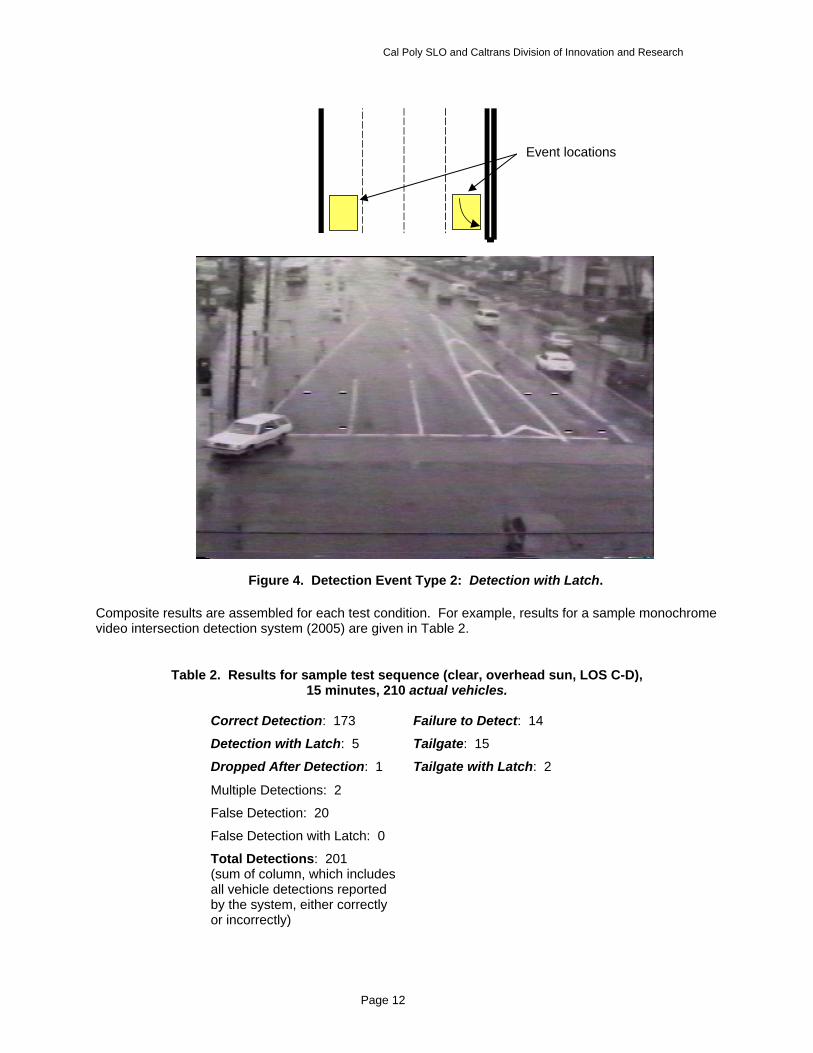
A sample observed vehicle detection event is illustrated in Figure 4, Event Type 2: Detection with Latch.
Cal Poly SLO and Caltrans Division of Innovation and Research
Page 12
Composite results are assembled for each test condition. For example, results for a sample monochrome video intersection detection system (2005) are given in Table 2.
Table 2. Results for sample test sequence (clear, overhead sun, LOS C-D), 15 minutes, 210 actual vehicles.
Correct Detection: 173 Failure to Detect: 14
Detection with Latch: 5 Tailgate: 15
Dropped After Detection: 1 Tailgate with Latch: 2
Multiple Detections: 2
False Detection: 20
False Detection with Latch: 0
Total Detections: 201 (sum of column, which includes all vehicle detections reported by the system, either correctly or incorrectly)
Figure 4. Detection Event Type 2: Detection with Latch.
Event locations
Cal Poly SLO and Caltrans Division of Innovation and Research
Page 13
During a given test interval representative of a specific traffic and environmental condition in the Test Suite, the total number of cases in which each vehicle detection type occurs constitutes a MOE for the system under that test condition. Therefore, a report exemplified by Table 2 is a definitive and comprehensive statement of the accuracy of the system under the given condition. The collection of such reports over a reasonably comprehensive range of test conditions, suggested in Table 1, constitutes an overall MOE for a given detection system.
In addition, an indirect but possibly more relevant MOE can be reported by assessing the ultimate effect of the detection system on the correctness of the resultant signal phase actuation. We subdivide the phase actuation events into three types for each of the two main signal intervals possible for each approach set (usually a through approach or protected left or right):
Red Interval (Effecting Actuation of Red/Green Transition):
1. Correct actuation
2. Failure to actuate correctly
3. False actuation
Green Interval (Effecting Actuation of Green/Red Transition):
4. Correct green extension
5. Potential failure to extend green
6. Potentially false green extension
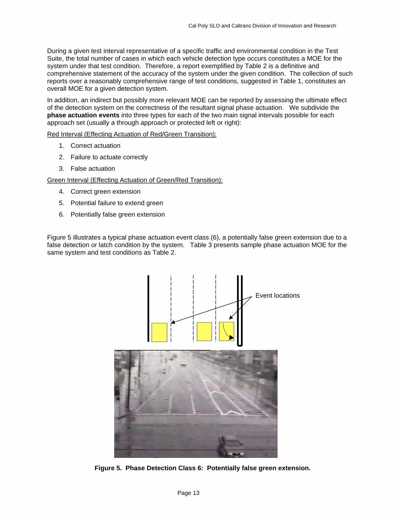
Figure 5 illustrates a typical phase actuation event class (6), a potentially false green extension due to a false detection or latch condition by the system. Table 3 presents sample phase actuation MOE for the same system and test conditions as Table 2.
Figure 5. Phase Detection Class 6: Potentially false green extension.
Event locations
Cal Poly SLO and Caltrans Division of Innovation and Research
Page 14
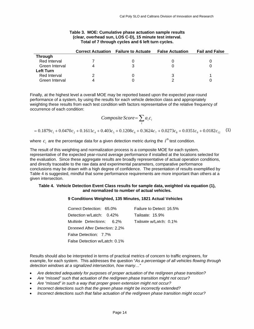
Table 3. MOE: Cumulative phase actuation sample results (clear, overhead sun, LOS C-D), 15 minute test interval.
Total of 7 through cycles and 6 left turn cycles.
Correct Actuation Failure to Actuate False Actuation Fail and False Through Red Interval 7 0 0 0 Green Interval 4 3 0 0 Left Turn Red Interval 2 0 3 1 Green Interval 4 0 2 0
Finally, at the highest level a overall MOE may be reported based upon the expected year-round performance of a system, by using the results for each vehicle detection class and appropriately weighting these results from each test condition with factors representative of the relative frequency of occurrence of each condition:
∑=i
iicaScoreComposite
1298765421 0182.00351.00273.03624.01208.0403.01611.00470.01879.0 ccccccccc ++++++++=
where ic are the percentage data for a given detection metric during the thi test condition.
The result of this weighting and normalization process is a composite MOE for each system, representative of the expected year-round average performance if installed at the locations selected for the evaluation. Since these aggregate results are broadly representative of actual operation conditions, and directly traceable to the raw data and experimental parameters, comparative performance conclusions may be drawn with a high degree of confidence. The presentation of results exemplified by Table 4 is suggested, mindful that some performance requirements are more important than others at a given intersection.
Table 4. Vehicle Detection Event Class results for sample data, weighted via equation (1), and normalized to number of actual vehicles.
Results should also be interpreted in terms of practical metrics of concern to traffic engineers, for example, for each system. This addresses the question “As a percentage of all vehicles flowing through detection windows at a signalized intersection, how many…”
• Are detected adequately for purposes of proper actuation of the red/green phase transition? • Are “missed” such that actuation of the red/green phase transition might not occur? • Are “missed” in such a way that proper green extension might not occur? • Incorrect detections such that the green phase might be incorrectly extended? • Incorrect detections such that false actuation of the red/green phase transition might occur?
(1)
9 Conditions Weighted, 135 Minutes, 1821 Actual Vehicles
Correct Detection: 65.0%Detection w/Latch: 0.42%Multiple Detections: 6.2% Dropped After Detection: 2.2%False Detection: 7.7%False Detection w/Latch: 0.1%
Failure to Detect: 16.5% Tailgate: 15.9%Tailgate w/Latch: 0.1%

Cal Poly SLO and Caltrans Division of Innovation and Research
Page 15
Test Protocol Variations Resulting from System Vendor Concerns
As discussed in the prior narrative, vendor-imposed test restrictions precluded the use of a standardized video test suite, the basis of the protocol developed for system tests under this study. As a result, we considered possible alternative plans that did not rely on the use of a identical video feeds to each system, while still providing results that were at comparable at least in terms of similarity of test conditions. Two variations of the test method evolved from this effort (repeated from Project Accomplishments and Impediments):
1. Test each candidate system at different intersections, selected, set up and approved by each of the detection system manufacturers. This approach assures that the system manufacturers have endorsed the installation and locations. However, it prevents the direct comparison of results between different systems since testing would occur using different traffic streams and under different environmental and illumination conditions.
2. Install all systems on the same approaches at the same intersection, with cameras positioned as closely together as possible. Run tests concurrently, with either no system of only one system actually actuating the signal. This requires that the camera mounting structure, typically a luminaire mast arm, be of sufficient strength to support multiple cameras in addition to the luminaire head. All except one camera would be positioned suboptimally. Since only one system would actually control the signal, some concerns about optimality of the operational conditions for each system would be possible. And most significant for the study, each system would have to loaned or purchased, installed and “tuned” by the manufacturer at the expense of the project, which was not budgeted.
Of these alternatives, we advise the latter method since it can produce data that would allow more direct performance comparisons between systems. System vendors and financial considerations favor the former, but since test conditions and system configurations are not directly comparable, comparison results would be of questionable validity.
Research Tasks Completed Select and negotiate access to evaluation systems
A significant negotiation and consultation process was completed in an effort to obtain access to existing systems to be subjected to evaluation. System vendors or manufacturers were expected to cooperate in this process to assure the proper setup and test environment for each system. With the assistance and guidance of Caltrans project coordinators, we located, select and worked with local traffic management jurisdiction to obtain to identify and instrument test intersections.
Product information and research literature survey
We completed a comprehensive review of both research literature and commercial product information, to update our knowledge of the technical state-of-the-art, current products on the market, and any newly applicable standards and similar work by other investigators.
Refine test protocols in consultation with Caltrans
The proposed test procedures, MOEs and test protocols described in the proposal were modified extensively in response to restrictions and concerns raised by product vendors, following initial indications of full cooperation. We produced and received Caltrans approval of a final test methodology and protocol, compatible with all initially-proposed products and practical testing and budgetary constraints.
Field acquisition of video and signal control data, lab data tests and data reduction
The initially-approved test protocol relied upon the creation of a video test suite, acquired form video cameras at existing VTDS-equipped intersections. This would be recorded along with encoded signal phase information and the output of loop detector (if available) at the selected test locations. Since the use of a standardized video test suite was prevented by vendor restrictions, this research task and all
Cal Poly SLO and Caltrans Division of Innovation and Research
Page 16
subsequent data analysis tasks based the use of this test suite for system evaluation could not be performed.
Establishment of Framework and Acceptable Compromise Protocols for Video Detection System Testing
The completion of extensive preparatory work, including selection and instrumentation of test intersections, and negotiation of compromise test protocols acceptable to all except one system vendor constitute a significant contribution, despite the ultimate lack of comparison test results from this study. If future funding permits the purchase and installation of video detection systems without the volunteer cooperation of the system vendors, testing could proceed immediately.
Final Report
A final report has been prepared describing all project activities, lessons learned, and the facilities and protocols now in place to permit possible future testing of video detection systems if future funding permits the purchase and funded installation of these systems, independent of vendor cooperation. Aware of the potentially significant impact our reported experience may have on the manufacturers and vendors of the systems intended to be evaluated, this report should be considered Caltrans-internal until authorization for publication is granted.
Cited References
1 Hoose, Neil. Automatic traffic monitoring from video images, Proceedings - Conference of the Australian Road Research Board, n pt 6, Traffic Data and Analysis, 1990, p 37-54. 2 MacCarley, C.A. Evaluation of Closed-Circuit Television Technology for Application in Highway Operations, Final Project Report, Caltrans Contract 51J932, California Polytechnic State University, San Luis Obispo, CA., 1992. 3 MacCarley, C.A., Need, D., Neiman, R. Video Cameras for Roadway Surveillance: Technology Review and Product Evaluation Results, Trans Research Record No.1410, National Research Council, Washington D.C., 1993. 4 MacCarley, C.A., S. Hockaday, D. Need, S. Taff, Evaluation of Video Image Processing Systems for Traffic Detection, Transportation Research Record No. 1360, National Research Council, Washington D.C., 1992. 5 MacCarley, C.A., L. Ponce. Video Technologies for Roadway Surveillance and Automated Detection, Proc. Society of Automated Engineers International Congress, Detroit, January, 1995. 6 Klein, Lawrence A., Traffic parameter measurement technology evaluation. Proc. IEEE-IEE Vehicle Navigation and Informations Systems Conference, 1993, p 529-533 7 Klein, Lawrence A., Kelley, Michael R.; Mills, Milton K. Evaluation of Highway Sensing and Detection Technologies. Proceedings of SPIE - The International Society for Optical Engineering, v 2344, 1995, p 42-53. 8 MacCarley, C.A., Advanced Imaging Techniques for Traffic Surveillance and Hazard Detection, Intellimotion, Vol 6 No. 2, Partners for Advanced Transit and Highways, University of California, Berkeley, March 1997. 9 MacCarley, C.A., Evaluation of Infrared and Millimeter-wave Imaging Technologies Applied to Traffic Management, Proc. SAE International Congress and Exhibition, Society of Automotive Engineers, Detroit, March 2000. Also SAE Transactions Journal of Passenger Car Electronic and Electrical Systems, August, 2001. 10 SRF and Associates, Field Test of Monitoring of Urban Vehicle Operations Using Non-Intrusive Technologies, Final report, Part IV. for the Minnesota Dept. of Transportation, 1999. Available on the web at http://srfa.net/ 11 MacCarley, C.A., J. Moore, M. McNally, R. Jayakrishnan. City of Anaheim / Caltrans / FHWA Advanced Traffic Control System Field Operational Test Evaluation Task C, Video Detection System, Final project report, Caltrans agreement No. SA 1272-18286, PATH University of California, Berkeley, April 18, 1998. 12 McNally, Michael G. (Univ of California); Mattingly, Stephen P.; Moore, James E.; Hu, Hsi-Hwa; MacCarley, C. Arthur; Jayakrishnan, R., Evaluation of Anaheim adaptive control field operational test. Institutional issues. Transportation Research Record, n 1683, Nov, 1999, p 67-77.

Cal Poly SLO and Caltrans Division of Innovation and Research
Page 17
13 MacCarley, C.A., and Palen, J.A. Evaluation of Video Traffic Sensors for Intersection Signal Actuation: Methods and Metrics, Paper No. 02-3920, 81st Trans Research Board Annual Meeting, Washington, DC., 2002. 14 Oh, Jutaek, Leonard II, John D. Vehicle detection using video image processing system: Evaluation of PEEK video trak. Journal of Transportation Engineering, v 129, n 4, July/August, 2003, p 462-465. 15 Bahler, Stephen J. (Minnesota Dep of Transportation); Kranig, James M.; Minge, Erik D. Field test of nonintrusive traffic detection technologies. Transportation Research Record, n 1643, Nov, 1998, p 161-170. 16 Kastrinaki, V. (Digit. Image/Sign. Proc. Laboratory, Department of Electronics, Technical University of Crete); Zervakis, M.; Kalaitzakis, K. A survey of video processing techniques for traffic applications. Image and Vision Computing, v 21, n 4, 2003. 17 Bullock, D., J. Sturdevant, Project Proposal to Indiana DOT, Project No. C-36-17QQQ, File No. 8-4-69 SPR-2869, 2004.
Appendix A
Video detection system manufacturers and points of contact, last updated September 2008.
Citilog, Inc. Web Address Corporate: http://www.citilog.com/index_en.php
Web Address Product: http://www.citilog.com/en/applications/intersection.php
Product Specs: http://www.citilog.com/en/applications/doc/MediaCity_Engl_le.pdf
Company Info:
355 W. Lancaster avenue - Building E
Haverford, PA 19041
Tel: 215 609 4945
Fax: 484 873 2292
[email protected] Contact Info:
Eric Toffin
1-215-609-4945
*Direct Contact:
Dr Jérôme Douret
Innovation & Product Marketing Unit
19-21 rue 8 mai 1945
94110 Arcueil, France
Tel: +33 1 41 24 34 60
Cal Poly SLO and Caltrans Division of Innovation and Research
Page 18
Std: +33 1 41 24 34 54
Product Names:
MediaCity
Product Info:
Video Inputs: Up to 4 video inputs (PAL/NTSC)
Storage: CompactFlash (Hard disk an option)
Outputs: Isolated open collectors, serial port (RS232, RS 485), TCP/IP
Network connection: (xDSL, Ethernet, ATM...)
Uses standard color or black and white fixed cameras
Additional Notes:
-Systems still not deployed within California
-New product planned to be released at the end of year
*Corresponded via email with Jerome
Traficon USA LLC Web Address: http://www.traficon.com/index.jsp
Company Info:
10161 Park Run Drive, Suite 150 Las Vegas, NV 89145, U.S.A.
Tel.: 1 (702) 851-5880 Fax: 1 (702) 851-5881 E-mail: [email protected]
Contact Info:
Bill Klyczek - Product Manager
Cell: 571-265-2828
Official Distributor Info:
Kar-Gor, Inc 2769 19th Street SE Salem Oregon 97302
Website: http://www.kargor.com/
Distributor Contact:
Gordon Dale - Principal [email protected] Tel: (503) 315-9899 Fax: (503) 315-9913
Product Names:
TrafiCam2 (Sensor and I/O Board)
Cal Poly SLO and Caltrans Division of Innovation and Research
Page 19
VIP3D.1 & VIP3D.2 (Detection Boards)
Viewcom/E
TrafiCam (2nd Generation)
Web Address: http://www.kargor.com/Traficam.html
Product Specs: http://www.kargor.com/TrafiCam2%20%2002-06.pdf
Product Info: Sensor
CMOS camera and detector in one compact sensor
Presence detection up to eight zones & are Direction Sensitive
Four isolated digital outputs to supply zone-state information
Configuration of sensor done via a portable computer or handheld PDA with preinstalled Traficon software
Also Available: Wireless TrafiCam & Solar Power TrafiCam
Product Info: I/O Board
TrafiCam I/O Edge module connects up to four TrafiCam Detectors
Fits directly into a 170 Type, NEMA TS-1 and TS-2 input file
Serial connection made via the TrafiCam I/O module and a PDA or PC for setup
Four outputs are available on the card itself; the additional outputs are transferred to the controller via Traficon 2, 4 or 12 I/O expansion modules
VIP3D.1 & VIP3D.2 (Detection Boards)
Product Specs: http://www.kargor.com/VIP3D.1_&_VIP3D.2___05=12.pdf
Product Info:
VIP3D.1 monitors one camera, VIP3D.2 monitors two cameras
The VIP3D.1 provides eight data detection zones, VIP3D.2 provides four data detection zones per camera
Analog video output with overlay of system data & detection lines
RS-232C service ports for data collection & firmware update (Software required)
Viewcom/E
Product Specs: http://www.kargor.com/VIEWCOM_E_USAsize_Mar03_sb.pdf
Product Info:
Ethernet communication for image and data transfer (10Mb/sec) via RJ-45 connector
RS232-C communication for image and data transfer via F DB9 connector
RS-485 communication within a rack for data acquisition via EDGE connector
Analog video output with overlay of system information
6 video inputs (all switchable)
Performs digitization & hardware based JPEG compression of images
Additional Notes:
* Met with Bill Klyczek at ITE show in Anaheim 8/18
Cal Poly SLO and Caltrans Division of Innovation and Research
Page 20
Peek Traffic Corporation * Old Web Address: http://www.ustraffic.net (Still contains relevant material)
*Video Products Manager info:
Ronald Featherston Phone: (972) 208-8535 Mobile: (972) 837-5216 Fax: (866) 456-4398 Email: [email protected]
Official Distributor Addresses:
Northern CA
J A M Services
7650 Hawthorn Place Suite 2
Livermore, CA 94550-7127
http://www.jamservicesinc.com
Southern CA
JTB Supply Co.
1030 Batavia Suite A
Orange, CA 92867
http://www.jtbsupplyco.com
Distributor Contact Info: (May be no longer valid)
Northern CA
Jeff Momaney
Ph: 925-455-5267
Fax: 925-455-5348
Email: [email protected]
Southern CA
Jeff York
Ph: 714-639-9498
Fax: 714-639-9488
Email: [email protected]
Product Names:
UniTrak (Version 2)
VideoTrak-Plus
VDS Camera
Additional Notes:
Camera Interface Panel specs on file
Could not locate new website for Peek USA
Cal Poly SLO and Caltrans Division of Innovation and Research
Page 21
Met with Ron Featherston at ITE show in Anaheim 8/18
Deployment:
UniTrak (Version 2)
Web Address: http://www.ustraffic.net/products/video/unitrac.html
Product Specs: http://www.ustraffic.net/products/video/UniTrak-05.pdf
Product Info:
Connections: RJ-45 for serial port PC connection, BNC for video in, RCA for video out
Bus interface : 44-pin standard detector card edge connector
Video processing module supports EIA standard (NTSC monochrome) CCD cameras
Detection features are compatible with NEMA TS-1/TS-2, Type 170/179, Type 2070, and ATC controllers.
Displays on site traffic scene with visual verification of vehicle detection
Flexible configuration of up to 26 detection zones logically mapped to as many as 8 outputs
Only mouse and monitor are needed for full configuration
VideoTrak-Plus
Web Address: http://www.ustraffic.net/products/video/videotrak.html
Product Specs: http://www.ustraffic.net/products/video/VideoTrak-Plus-05.pdf
Product Info:
Video Processing Module supports RS-170, NTSC, CCIR or PAL format CCD cameras
Detection features are compatible with NEMA TS-1/TS-2, Type 170/179, Type 2070 and ATC controllers.
Remote or onsite display of the traffic scene provides visual verification of detection accuracy
Available in two models, which support up to 4 or 8 cameras - with as many as 32 detection zones per camera - providing up to 128 or 256 detection zones, depending on model
Statistical Outputs:
Number of vehicles (volume/counts)
Average speed (mph/kph)
Lane occupancy (% time lane is occupied)
Density (volume/speed)
Headway (avg. in seconds)
Delay (avg. delay in seconds)
Queue length (foot/meters)
Vehicle length (avg. in ft/meters)
Detection Zone Conditional Attributes:
Detect always
Detect only if phase is (green/red)/is not (green/red)
Detect only if zone X has no occluding vehicles
Cal Poly SLO and Caltrans Division of Innovation and Research
Page 22
Detect always, but only accumulate statistics if the phase is red/yellow/green
VDS Camera (for unitrak and videotrak detection systems)
Web Address: http://www.ustraffic.net/products/video/vpk351b.html
Product Specs: http://www.ustraffic.net/products/video/VDS%20Camera.pdf
Product Info:
High Sensitivity allows both VideoTrak® & Unitrak™ to operate well in low-light conditions
Imager: Interline transfer CCD, 1/3-inch image format
Active Picture Elements 582H × 494V
Horizontal Resolution 570 TVL
Built-in temperature-sensing window heater /defogger Bright headlights in darkness are detected without blooming or interline smear
Autoscope (Econolite) Web Address: http://autoscope.com
Official Distributor:
Econolite Control Products, Inc. Corporate Headquarters & Southern California Office 3360 E. La Palma Ave. Anaheim, CA 92806 Ph: 714.630.3700 Fax: 714.630.6349 E-mail: [email protected] Web: www.econolite.com
Distributor Contact Info:
Doug Henderson – Regional Manager
Ph: 714-630-3700
Email: [email protected]
Scott Robinson - Product Manager Ph: (714) 630-3700 Email: [email protected] Direct Contact: Dave Candey, Jr Technical Support Manager
Ph: 714-630-3700 x236 Cell: 530-304-7230 Fax: 916-648-9837 Email: [email protected]
Cal Poly SLO and Caltrans Division of Innovation and Research
Page 23
Product Names:
Solo Terra
RackVision Terra
AIS Camera (Autoscope Image Sensor)
Autoscope Terra Access Point (TAP)
Deployment:
Solo Terra
Web Address: http://www.autoscope.com/products/solo_terra.htm
Product Specs: http://www.autoscope.com/products/dl/SoloTerra_us.pdf
Product Info:
Integrated color camera, zoom lens, and dual-core processor for advanced image processing
CCD ¼ in. diam. (4.5 mm), Horizontal resolution: NTSC > 470 TVL, PAL >460 TVL
EasyLink (broadband communications (up to 5 MB/ sec) with RJ-45 connection from required Terra Interface Panel (TIP)
Streaming digital MPEG-4 video output
Terra Access Point (TAP) also provides standard NTSC or PAL full-motion video output to an analog video monitor
RackVision Terra
Web Address: http://www.autoscope.com/products/rackvision_terra_us.htm
Product Specs: http://www.autoscope.com/products/dl/RackVision_Terra_us.pdf
Product Info:
Connects to existing color or B&W Autoscope Image Sensor (AIS) cameras or other approved CCTV cameras
Video Input: PAL, CCIR, NTSC or RS170, BNC connector on front
Video Output: PAL or NTSC, BNC connector on front, MPEG-4 digital streaming video via EasyLink
Communications: RJ45 connector for EasyLink Ethernet 10/100 MB/s on front & USB 2.0 connector for USB mouse
Detector I/O Outputs: (open collector, selectable active low or high), 4 Rear edge connectors (jumper selectable), 24 Front connectors
Detector Inputs: 16 Front connectors
AIS Camera (Autoscope Image Sensor)
Web Address: http://www.autoscope.com/products/ais.htm
Product Specs: http://www.autoscope.com/products/dl/AIS_us.pdf
Product Info:
Imaging Device: ¼” color CCD
Video Formats: RS170, NTSC, CCIR and PAL
Cal Poly SLO and Caltrans Division of Innovation and Research
Page 24
Resolution: NTSC 460 TVL Horizontal, 350 TVL Vertical
Interface connector: MS 14-18P
B&W Video Output Connector: BNC
Auxillary Color Output BNC to separate coax cable
Autoscope Terra Access Point (TAP)
Web Address: http://www.autoscope.com/products/tap_nema.htm
Product Specs: http://www.autoscope.com/products/dl/TAP_nema.pdf
Product Info:
Supports up to 8 Solo Terra Sensors
Connectors: TIP Interface,TS2 port 1 connector 15 socket D-subminature with latching blocks, Video BNC, 2 USB 2.0 connectors for mouse
Video Output: NTSC and PAL
Communications: Easylink Broadband to TIP, RS-485 detector port on edge connector (jumper-selectable)
Interface detector outputs directly to NEMA TS1/TS2, Type 170/179, or 2070 ATC controllers
Coverts streaming digital MPEG4 to standard NTSC analog video to view locally
Additional Notes:
Old products and Autoscope TIP specs on file
Met with Dave Candey at ITE show in Anaheim 8/18
Iteris Web Address: http://www.iteris.com
Company Info:
Corporate Headquarters - Iteris, Inc. 1700 Carnegie Avenue Suite 100 Santa Ana, CA 92705 Phone: (949) 270-9400 Fax: (949) 270-9401 Contact Info:
Western Region Stan Garren Regional Sales Manager
Cell: 661-435-2778 Fax: (949) 270-9441 [email protected]
Roger Koehler
Product & Account Manager

Cal Poly SLO and Caltrans Division of Innovation and Research
Page 25
Ph: 949-270-9621 Cell: 916-798-2878
Robert Ung
Director Vantage Applications & Product Support
Ph: 949-270-9687
Fax: 949-270-9446
[email protected] Product Names:
Vantage RZ4 Camera
Vantage Wireless Camera
VersiCam
Vantage Edge 2
Vantage Edge 2 I/O Module
Vantage TS2-IM Processor
Vantage RZ4 Camera
Web Address: http://www.iteris.com/vvd.aspx?q=10096&c=10011
Product Specs: http://www.iteris.com/upload/datasheets/Camera_Web_2008.pdf
Product Info:
Color or monochrome image sensors available
Latest CCD Sensing element and DSP technology
Imager Resolution: 768 x 494 effective pixels, 470 TV lines minimum
BNC connector for video at rear of housing
Separate connectors for power and video
Vantage Wireless Camera
Web Address: http://www.iteris.com/vvd.aspx?q=10098&c=10011
Product Specs: http://www.iteris.com/upload/datasheets/WirelessCam_Web_2008.pdf
Product Info:
Same info as Vantage RZ4 Camera
2.4GHz integrated wireless transmitter
Integrated antenna
1, 2 or 4 channel receiver configuration
VersiCam
Web Address: http://www.iteris.com/vvd.aspx?q=10120&c=6
Cal Poly SLO and Caltrans Division of Innovation and Research
Page 26
Product Specs: http://www.iteris.com/upload/datasheets/VersiCam_Web_2008.pdf
Product Info:
VersiCam is an integrated machine vision processor and camera solution. Designed for small or semi-actuated intersections, VersiCam offers the same high performance Vantage video detection in a low-cost package
Camera: Color image sensor, Latest CCD Sensing element and DSP technology
Camera Processor: Vantage video detection algorithms, Stores 3 detector configurations
Interface Communications Controller: 6 virtual detection zones, 2 outputs (TS-1), USB mouse control, RS-232 serial port, RS-485 serial intercommunication, Full motion video output for setup and monitoring
Vantage Edge 2Processor
Web Address: http://www.iteris.com/vvd.aspx?q=10095&c=10011
Product Specs: http://www.iteris.com/upload/datasheets/Edge2_Web_2008.pdf
Product Info:
Available in single dual or quad video inputs
Extension modules in 2, 4 or 32 channel configurations
Up to 24 virtual zones per video input
Up to 24 outputs per video input
Communications: RS-232 serial port for ease of remote access and maintenance, USB for mouse control
Fits into Type 170/2070 input files, NEMA TS-1 and TS-2 detector racks
Video Input type: NTSC & PAL
1 input channel = Single BNC connector
2 input channel = Dual BNC connector
4 input channel = DB15 video input connector (cable supplied)
Output – All models, Single BNC connector
Detector I/O: Outputs: 4 on rear edge of module, Inputs : 4 on rear edge of module
Vantage Edge 2 I/O Module
Web Address: http://www.iteris.com/vvd.aspx?q=10095&c=10011
Product Specs: http://www.iteris.com/upload/datasheets/ExtensionMods_Web_2008.pdf
Product Info:
IO modules are available in 2-channel, 4-channel and 32-channel
8 Optically isolated inputs – IO module only
4 Optically isolated input – 2 and 4 channel EM
NEMA TS-1, TS-2 and Caltrans 170/2070 compatible
Interfaces with Edge2 video detection processors
Can be inter-mixed with existing Edge2 extension modules and Vantage Access and
Cal Poly SLO and Caltrans Division of Innovation and Research
Page 27
Vantage eAccess communications modules
Intermodule Conections: 2 x RJ45 – front
Vantage TS2-IM Processor
Web Address: http://www.iteris.com/vvd.aspx?q=10095&c=10011
Product Specs: http://www.iteris.com/upload/datasheets/TS2IM_Web_2008.pdf
Product Info:
The Vantage® TS2-IM (TS2 Interface Module) is a Bus Interface Unit (BIU) module that
allows video detection systems to communicate with TS-2 controllers using standard
protocols.
Mounts into any standard TS-2 BIU rack slot
64 detector output channels to the TS-2 Controller
Connectivity for up to four (4) Edge2 video detection processor modules
Uses SDLC addresses 8, 9, 10 and 11 for TS-2 controller communications
Monitors TS-2 phase information
Connectors: Backplane = Standard TS-2 BIU connector, Vantage= 8 x RJ45 receptacles (4 input, 4 output), SDLC TS-2 = DB15 connector
Additional Notes:
Additional product specs on file for accessories, software and remote management
* Met with Stan Garren, Roger Koehler & Robert Ung at ITE show in Anaheim 8/18
Siemens Web Address: http://www.itssiemens.com/index.html
Company Info: 8004 Cameron Road Austin TX 78754 USA Tel.: 512.837.8310 Fax : 512.837.0196
Contact Info:
Matt E. Zinn Technical Applications Specialist Siemaes Energy and Automation Inc. Intelligent Transportation Systems 2642 E. Cloud Road Cave Creek, AZ 85331 Ph: 602 315 3415
Cal Poly SLO and Caltrans Division of Innovation and Research
Page 28
fax 480 575 1406 [email protected]
Product Names:
EagleVision Video Detection Systems
Deployment:
Freemont,CA
EagleVision Video Detection System
Web Address: http://www.itssiemens.com/en/t_nav114.html#content-zone
Product Spec: http://www.itssiemens.com/en/Downloads/pdfs/EagleVision_OnePage.pdf
Product Info:
Video Features
• Eight detector zones
• Eight detector outputs
• IP Communications
• Color video
• Streaming video
• Java GUI
• OS Independent
Camera
• Linux OS
• Lumenera Camera
• Low Power Consumption
• 24 VDC @ <13w
• Power PC processor
Hardware features
• Plug and Play capable connection directly to a M50 or 2070 controller with a 1B card
• Direct 10-pin wires eliminate need for detector racks
• Option to connect directly to the Detector Input Panel
Additional Notes:
New Company in Video Detection
Met with Matt Zinn at ITE show in Anaheim 8/18
Cal Poly SLO and Caltrans Division of Innovation and Research
Page 29
Appendix B Supplemental Info from Selected Previous Research
The two primary centers for vide system testing have been Cal Poly San Luis Obispo in California http://www.google.com/search?hl=en&sa=X&oi=spell&resnum=0&ct=result&cd=1&q=UC+Berkeley+testing+of+video+traffic+detection+systems&spell=1, and Purdue University in Indiana http://docs.lib.purdue.edu/cgi/viewcontent.cgi?article=1750&context=jtrp . Some work has also been performed at the University of California Berkeley, via the Berkeley Highway Laboratory http://bhl.calccit.org/past_research.html and http://www.its.berkeley.edu/newsbits/winter2005/sensorsevaluation.pdf . Work at these institutions has been referenced in the text.
In addition to the evaluation work performed at these institutions, Texas Transportation Institute (TTI)17 and the University of Utah Traffic Lab (UTL)17 have done two previous studies on video detection systems.
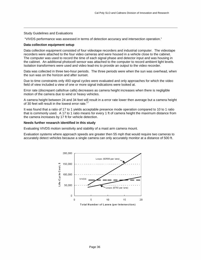
TTI’s study http://tti.tamu.edu/documents/0-2119-S.pdf and http://www.ptr.poli.usp.br/lemt/documents/08-2617.pdf was the more comprehensive body of work, examining the cost and installation of video imaging vehicle detection systems (VIVDS) and the effects of different configurations on system performance, including some safety-related deficiencies. No product comparison work was done. The graph below shows the life-cycle cost of a VIVDS system compared to inductive loops. This shows the projected annualized cost for the number of lanes under detection. The cost study included motorists’ delay, power consumption, purchasing, installation, maintenance, and liability due to a system failure.
Overview
Estimated 10% (650) of intersections in Texas use video imaging vehicle detection systems (VIVDS) and the instillations were done with “turnkey” arrangements with vendors of systems. This study is conducted to provide guidelines for optimal installation of VIVDS systems in Texas conditions.
The scope of the project extended to all types of intersections. The intersections “can be new or existing. It can be in an urban or rural environment and on a collector or arterial roadway. To the extent practical, the guidelines are applicable to all VIVDS products. They are applicable to detection designs that use one camera (for each intersection approach monitored) to provide detection at the stop line and, if needed, detection in advance of the stop line.”17
The study was also limited and does not evaluate the actual detection accuracy of any VIVDS to but is only studied for the use in “basic intersection(or interchange) control using presence-mod detection.”1
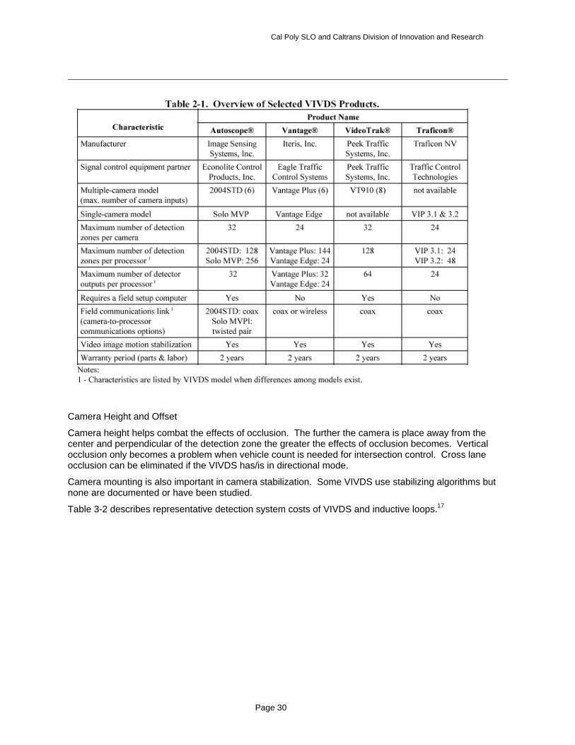
Table 2-1 from work completed at Purdue University, describes several VIVDS products.17
Cal Poly SLO and Caltrans Division of Innovation and Research
Page 30
Camera Height and Offset
Camera height helps combat the effects of occlusion. The further the camera is place away from the center and perpendicular of the detection zone the greater the effects of occlusion becomes. Vertical occlusion only becomes a problem when vehicle count is needed for intersection control. Cross lane occlusion can be eliminated if the VIVDS has/is in directional mode.
Camera mounting is also important in camera stabilization. Some VIVDS use stabilizing algorithms but none are documented or have been studied.
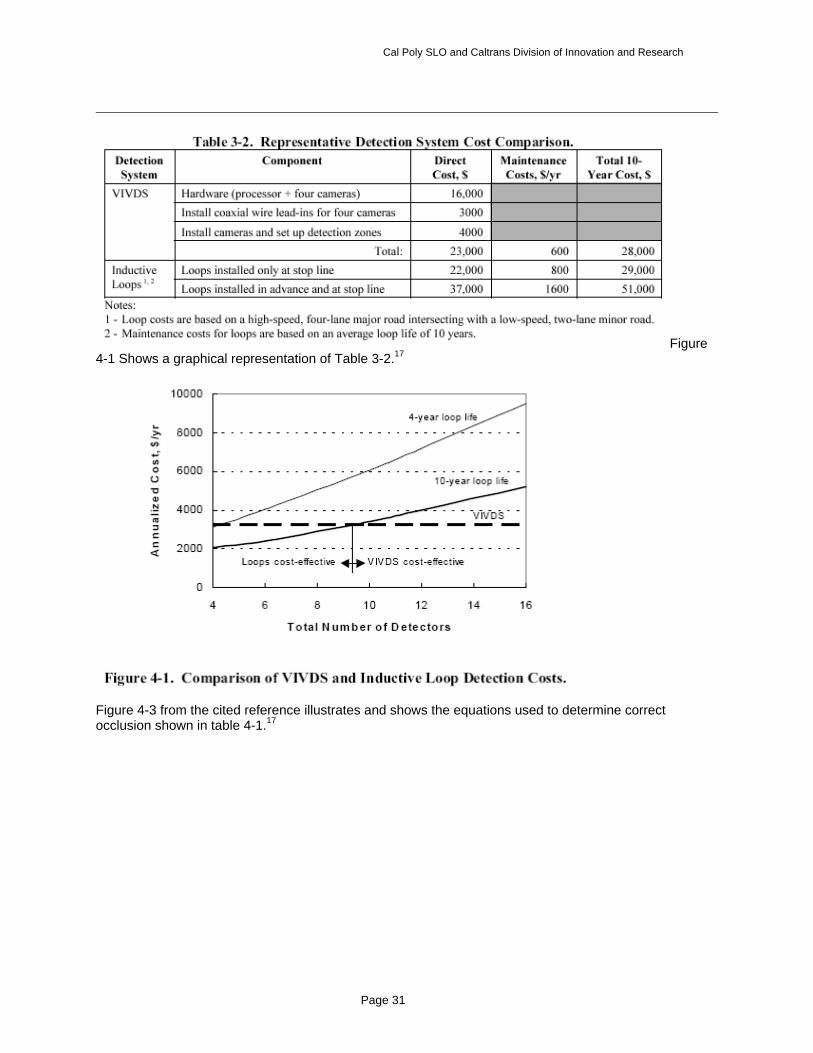
Table 3-2 describes representative detection system costs of VIVDS and inductive loops.17
Cal Poly SLO and Caltrans Division of Innovation and Research
Page 31
Figure 4-1 Shows a graphical representation of Table 3-2.17
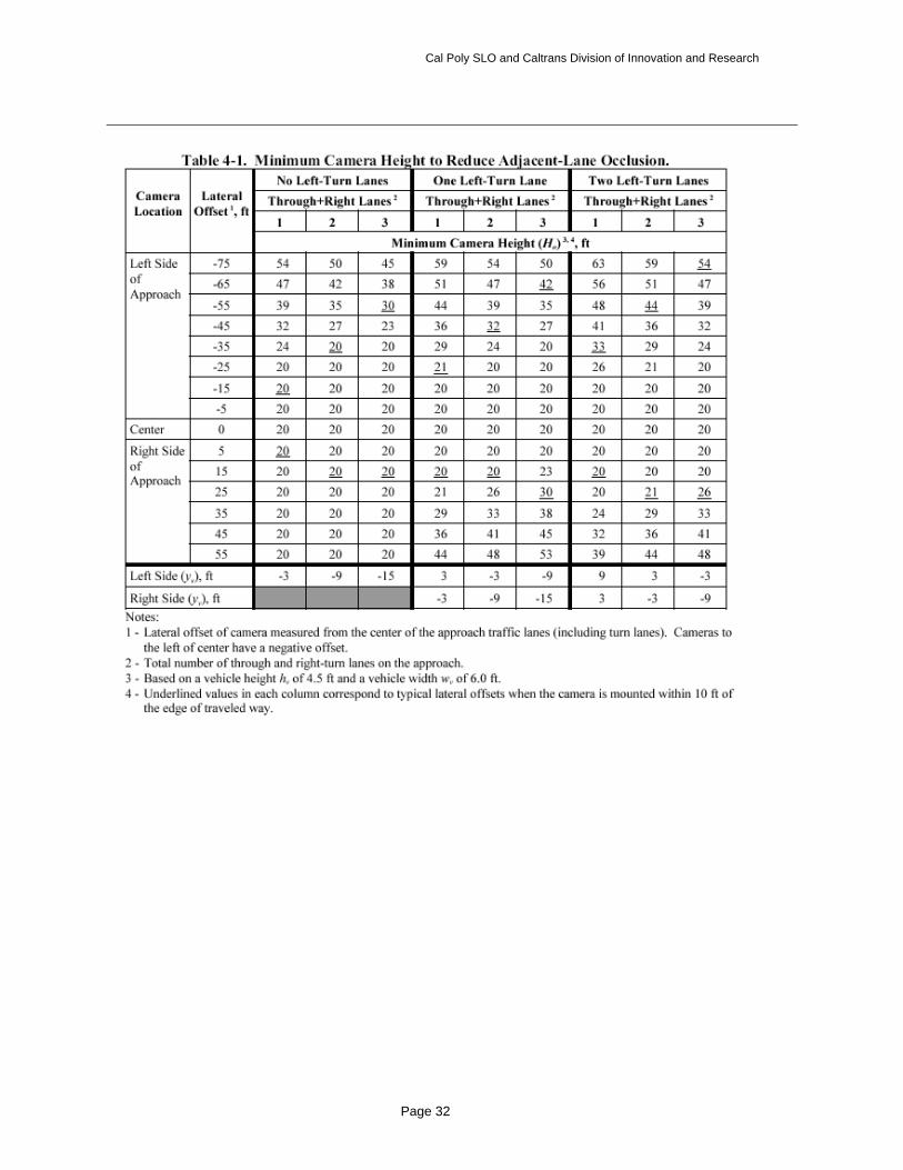
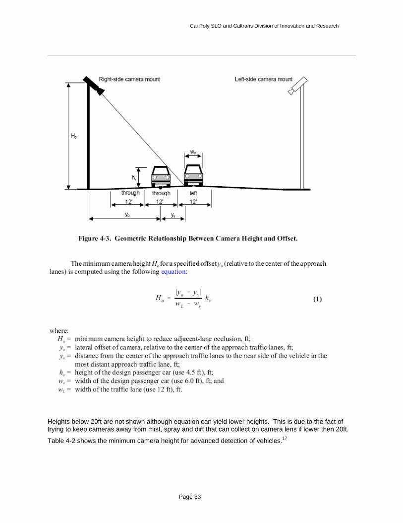
Figure 4-3 from the cited reference illustrates and shows the equations used to determine correct occlusion shown in table 4-1.17
Cal Poly SLO and Caltrans Division of Innovation and Research
Page 32
Cal Poly SLO and Caltrans Division of Innovation and Research
Page 33
Heights below 20ft are not shown although equation can yield lower heights. This is due to the fact of trying to keep cameras away from mist, spray and dirt that can collect on camera lens if lower then 20ft.
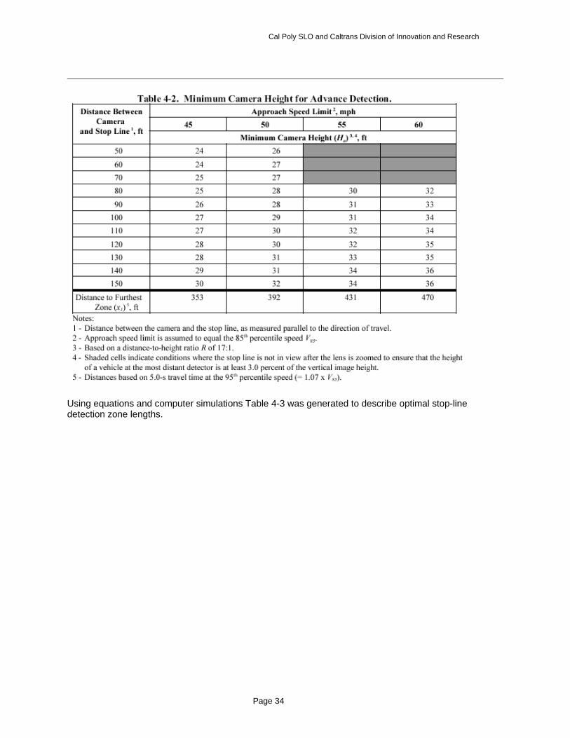
Table 4-2 shows the minimum camera height for advanced detection of vehicles.17
Cal Poly SLO and Caltrans Division of Innovation and Research
Page 34
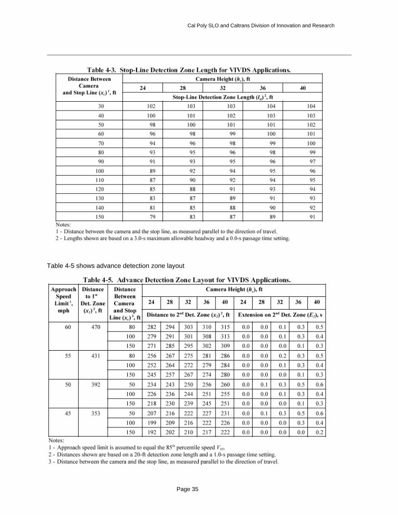
Using equations and computer simulations Table 4-3 was generated to describe optimal stop-line detection zone lengths.
Cal Poly SLO and Caltrans Division of Innovation and Research
Page 35
Table 4-5 shows advance detection zone layout
Cal Poly SLO and Caltrans Division of Innovation and Research
Page 36
Study Guidelines and Evaluations
“VIVDS performance was assessed in terms of detection accuracy and intersection operation.”
Data collection equipment setup
Data collection equipment consisted of four videotape recorders and industrial computer. The videotape recorders were attached to the four video cameras and were housed in a vehicle close to the cabinet. The computer was used to record the time of each signal phase and detector input and was housing in the cabinet. An additional photocell sensor was attached to the computer to record ambient light levels. Isolation transformers were used and video lead-ins to provide an output to the video recorder.
Data was collected in three two-hour periods. The three periods were when the sun was overhead, when the sun was on the horizon and after sunset.
Due to time constraints only 493 signal cycles were evaluated and only approaches for which the video field of view included a view of one or more signal indications were looked at.
Error rate (discrepant calls/true calls) decreases as camera height increases when there is negligible motion of the camera due to wind or heavy vehicles.
A camera height between 24 and 34 feet will result in a error rate lower then average but a camera height of 30 feet will result in the lowest error rate.17
It was found that a ratio of 17 to 1 yields acceptable presence mode operation compared to 10 to 1 ratio that is commonly used. A 17 to 1 ratio means for every 1 ft of camera height the maximum distance from the camera increases by 17 ft for vehicle detection.
Needs further research identified in this study
Evaluating VIVDS motion sensitivity and stability of a mast arm camera mount.
Evaluation systems where approach speeds are greater then 55 mph that would require two cameras to accurately detect vehicles because a single camera can only accurately monitor at a distance of 500 ft.
Cal Poly SLO and Caltrans Division of Innovation and Research
Page 37
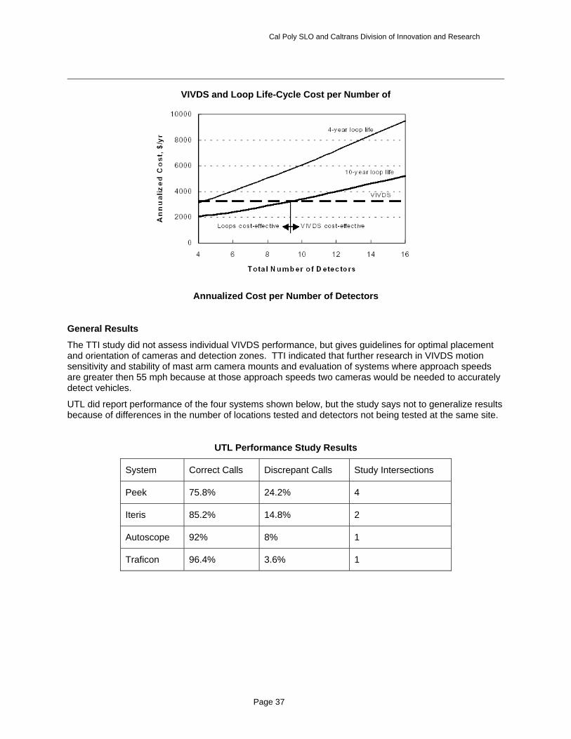
VIVDS and Loop Life-Cycle Cost per Number of
Annualized Cost per Number of Detectors
General Results
The TTI study did not assess individual VIVDS performance, but gives guidelines for optimal placement and orientation of cameras and detection zones. TTI indicated that further research in VIVDS motion sensitivity and stability of mast arm camera mounts and evaluation of systems where approach speeds are greater then 55 mph because at those approach speeds two cameras would be needed to accurately detect vehicles.
UTL did report performance of the four systems shown below, but the study says not to generalize results because of differences in the number of locations tested and detectors not being tested at the same site.
UTL Performance Study Results
System Correct Calls Discrepant Calls Study Intersections
Peek 75.8% 24.2% 4
Iteris 85.2% 14.8% 2
Autoscope 92% 8% 1
Traficon 96.4% 3.6% 1
Cal Poly SLO and Caltrans Division of Innovation and Research
Page 38
Appendix C Sample Vendor Contact Letter
Mr./Dr. _____
Contact Address
Dear Mr. Koehler,
It was a pleasure to speak with you and witness a demonstration of the ______ video intersection detection systems detectors at ______ . We are under contract to the California Department of Transportation to evaluate all state-of-the-art video detection systems for intersection signal actuation.
We would like to include the ______ detector in our study, and I request that you respond if _____ is interested in participating. Your input in cooperatively formulating the final test procedures would also be appreciated.
Our grant does not include funding to purchase any systems, but it is our intention to minimize any burden on manufacturers and vendors by either requesting the temporary loan of a system, or obtaining access to an existing system already deployed at a location in California.
We understand that different systems have different input requirements. From our discussions and your product literature, it appears that the _______ detectors can accept video inputs from any standard high-resolution NTSC color CCD camera, although your own compatible camera is preferred. This capability is a fundamental to the objective comparison test of the system, since it can be sourced from a standard test suite acquired by digitally recording the outputs of existing detection cameras along with signal phase information at several test intersections.
I can be reached at 805 781 8461 (consulting office) or 805 756 2317 (academic office).
Our contract monitor is Joe Palen of Caltrans Division of Research and Innovation, 916 654 8420.
I look forward to working with you and your colleagues.
Thank you.
Art MacCarley, Ph.D., PE.
Prof., Electrical and Computer Engineering
c. Joe Palen, Caltrans DRI