final project report - cal poly
TRANSCRIPT

FINAL PROJECT REPORT
Development of a Hydrogen Fueled Transit Vehicle
Submitted by
C. A. MacCarley, PE. Lundin Center for Hydrogen Energy Technology
Denver Research Institute University of Denver
Submitted to
E. K. Demos Environmental Officer
City and County of Denver
May 26, 1982

TABLE OF CONTENTS
1. Incentives for Investigation of Hydrogen as a Transit Bus Fuel. 1
2. Summary . . . . . . . . . . . . . . . . 1
3. Advantages and Limitations of Hydrogen as a Vehicle Fuel. 3
4. Hydrogen Production and Supply. 4
5. Technical Description 6
5.1 Summary.... 6
5.2 Fuel Injection Development 6
5.3 Turbocharger and Other Engine Modifications. 14
5.4 Hydrogen Fuel Storage System and Regulation Components 15
5.5 Electronic Safety Control System and Instrumentation 17
6. Operational Test Results. 19
7. References. 23
Tables
Figures
Appendices

1. INCENTIVES FOR INVESTIGATION OF HYDROGEN AS A TRANSIT BUS FUEL
The urban environment creates a unique set of requirements for public
transportation. A city bus system or similar urban transit system will only be
fully utilized if (1) it effectively serves a sufficient user population, and
(2) alternatives to its use, specifically the use of private automobiles,
become less attractive. With the possibility of hydrocarbon fuel shortages
becoming more imminent, and costs following a sharply rising trend, increased
demand for public transit may be anticipated. Meeting the needs of the
expanded user population will require the expansion and upgrading of existing
systems. But other requirements exist: clean air quality and independence of
the public transit system from the same oil price/availability situation that
would increase public transit demand.
The continued or expanded use of diesel powered buses meets neither of
these requirements. The need for the use of a synthetic fuel, or
electrification of the transportation circuit is obvious. The capital costs
involved in electrification are unnecessarily prohibitive. Among the few
synthetic fuels that may realistically be considered, hydrogen is a choice
worthy of cons ide ration as it effectively meets both requirements, and
integrates well with other urban needs, such as electric power peak-shaving or
refuse disposal.
2. SUMMARY
On June 1, 1980, the City and County of Denver contracted with the Lundin
Center for Hydrogen Energy Technology of the Denver Research Institute,
University of Denver, for modification of a Regional Transit District (RTD) bus
to operate on hydrogen. The intended use of this bus was for demonstration of
a non-polluting transit vehicle on the Denver Sixteenth Street Transitway Mall.
1

The vehicle modifications were to include the installation of high pressure
tanks for hydrogen fuel storage, and the conversion of the engine to hydrogen
as its operational fuel.
Many administrative and scheduling changes have occurred during the course
of the contract period. Due to delays in the acquisition of mall buses by the
RTD, the intended mall vehicle, a new Vetters airport apron type bus, was not
available for conversion to hydrogen as originally planned.
A modified project work schedule was drawn up which would allow the latest
possible delivery date of the bus from the RTD. This is shown in Appendix 1.
This schedule anticipated that a minimum of eight months would be required
fo 11 owing the de 1i very date of the bus to comp 1ete the proposed conversion
work.
Two contract time extentions were granted extending the contract period to
December 31, 1981, due to the unavailability of the bus. Realizing that the
intended bus would not be available until early 1982, the RTD provided a
substitute bus for the hydrogen conversion in August of 1981. This was a 1975
FMC circulator bus; one of several which had been withdrawn from service by RTD
and was scheduled for replacement. Redesign of both the hydrogen storage
system and the engine modifications was required to accomodate this vehicle.
Considerable effort was also required to refurbish this bus to an acceptable
condition for use as a demonstration vehicle. In May, 1982, the conversion
work was completed and preliminary tests indicated that all original design
specifications had been met or exceeded.
This report provides a description of the work done under this contract,
technical details of the vehicle modification, disclosure of preliminary test
data and observations, and a description of vehicle operating procedures. It
is important to note that this is an experimental vehicle employing many
2

technical approaches which have not previously been implemented or tested. It
is therefore imperative that this vehicle only be operated or refueled by
personnel with sufficient experience in hydrogen engine technology and hydrogen
fuel handling. Operation or refueling by insufficiently qualified personnel is
hazardous and could result in a potentially catastrophic situation.
3. ADVANTAGES AND LIMITATIONS OF HYDROGEN AS A VEHICLE FUEL
The most compelling incentive for use of hydrogen as a vehicle fuel is the
low pollution nature of its combustion. For fuel-air mixtures leaner than 0.65
of the stoichiometric (chemically correct) fuel-air ratio, the combustion of
hydrogen in air results in essentially no harmful emissions. The primary
exhaust product is water. For mixtures between 0.65 and 0.95 of
stoichiometric, certain levels of NOx (oxides of nitrogen) are produced as a
result of the combination of nitrogen and oxygen from air at the high
combustion temperatures. Lower NOx levels are encountered with precisely
stoichiometric fuel-air mixture, although difficulties in achieving a perfectly
homogeneous stoichiometric fuel-air charge prevent the use of such mixtures
without deterioration of efficiency.
The unique zero-pollution nature of lean-burn hydrogen engine operation
makes hydrogen particularly attractive in vehicle applications which require
the performance of an internal combustion engine, but the zero-pollution
features previously only achievable with electric vehicles.
In addition, engines operated on hydrogen are noted for their high thermal
efficiency. A hydrogen fueled vehicle can be expected to achieve higher miles
per BTU ratings than equivalent vehicles operated on gasoline or diesel fuel.
Several disadvantages of hydrogen must be pointed out. Hydrogen possesses
substantially different combustion properties than most common fuels. These
are summarized in Table 1. A hydrogen-air mixture can be ignited much more
3

easily than mixtures of other common fuels with air. This is fundamentally due
to the very wide flammability limits, and the very low minimum ignition energy
of hydrogen in air. One important ramification of these properties is that
special fuel handling procedures must be observed to assure safe refueling and
operation of a hydrogen vehicle. An additional ramification of hydrogen's
ignitability is the tendency of hydrogen engines to backfire in the intake
manifold when conventional gaseous fuel carburetion equipment is used for the
conversion of the engine. One of the key technical tasks of this project was
elimination of this backfire problem. This was accomplished through the use of
an experimental fuel injection system, which will be described later in this
report.
Another major difficulty is the lack of an adequate means for storage of
sufficient hydrogen on-board a vehicle. Several means for on-board hydrogen
storage have been suggested or demonstrated. These are summarized in Table 2.
It was originally proposed that a metal hydride fuel storage system be
used for fuel storage on the bus. Due to budgetary limitations, this phase of
the project was not funded. Therefore, the least expensive means for on-board
hydrogen storage was selected. This was compressed storage in high pressure
cylinders. This method suffers from a poor hydrogen density per system weight
and per system volume. This imposes a range limitation on the vehicle since an
inadequate amount of fuel can be stored on board. For the bus, nine pressure
cylinders are used to provide approximately one hour of operation in typical
service. Details of this system are provided later in this report.
4. HYDROGEN PRODUCTION AND SUPPLY
Since the practicality of operation of a bus on hydrogen depends heavily
upon the availability and economics of a hydrogen supply, some discussion will
4

be presented on this topic. For a more detailed assessment of hydrogen as an
urban transit fuel, the reader is directed to reference 1.
Hydrogen is, at present, produced only in small scale, often as a
by-product of industrial operations such as chlorine production and hydrocarbon
reformation. The generation process in widest use is steam reformation of
methane, in which natural gas is used as the energy feedstock. This method
would be neither practical or economical for large scale hydrogen production to
support hydrogen use as a fuel.
A well known means for hydrogen production is electrolysis of water.
Electric power is required, which must be produced using fossil fuels, nuclear,
hydroelectric, solar or wind energy. Hydrogen may be produced directly from
heat inputs using one of many available thermochemical water splitting cycles,
such as the sulphur-iodine cycle (2). Hydrogen may also be produced by coal
gasification (3). It is possible to decompose water in a one step process at
high temperature in the presence of a catalyst. Very high temperatures are
required and conversion efficiency is poor, but the simplicity of such a
process might be an attractive means for utilizing the very high temperatures
available at the focal point of a concentrating solar collector, or in possible
future application of a fusion reactor (4). Processes are presently under
study for direct photoelectrolytic decomposition of water via solar energy (5).
Certainly the most proven existing technology hydrogen generation process
is electrolysis. A unique opportunity exists for utilization of off-peak
electric power in conjunction with hydrogen fueled city buses and fleet
vehicles. Refueling of fleet vehicles normally takes place at night--a period
of low demand on the electric power grid. Electrolytic production of hydrogen
for use as a vehicle fuel may be a good means for off-peak power utilization,
improving the cost effectiveness of i n-p 1ace power generation facilities.
5

Studies have been done on the use of electrolytically produced hydrogen stored
in metal hydride tanks, and later used in gas turbine powered generators or
fuel cells for utility peak shaving (6, 7). An integrated peak power storage
vehicle fueling system might solve two key urban problems simultaneously.
5. TECHNICAL DESCRIPTION
5.1 Summary
Modifications to the bus to enable it to operate on hydrogen included the
conversion of the engine by use of a specially designed hydrogen fuel injection
system, the installation of a turbocharger and its accessories, the
installation of high pressure cylinders for hydrogen fuel storage, the
installation of hydrogen regulation and delivery components, and the
installation of an electronic safety control system and appropriate
instrumentation.
5.2 Fuel Injection Development
The development of a means for elimination of backfiring in hydrogen
engines was a problem that required a solution in order to achieve acceptable
operational characteristics for the bus. Considerable effort was made to
better understand the reasons behind backfiring and then to implement a means
for preventing backfiring and achieving adequate engine power output levels.
Although the problem of induction ignition is not unique to hydrogen, it
is certainly more pronounced with hydrogen than with other gaseous or liquid
fuels. This is fundamentally due to the exceptionally low minimum ignition
energy (0.02mJ at ~=1) and the wide flammability limits (0.21 < ~ < 7.34) of a
hydrogen air mixture. The equi va1ence ratio ~ is defined as the actua1
fuel-air molar ratio divided by the stoichiometric or chemically correct ratio.
Several mechanisms by which a backfire may be initiated have been identified or
suggested. The surfaces of the exhaust valve, piston or spark plug can ignite
6

a fuel-air charge if their temperatures are sufficiently high. Combustion
chamber hot spots can also be conducive to backfiring, due to their high local
temperatures. This situation may be accentuated by the very small
(0.6 mm for 0=1) surface quenching distance of the hydrogen-air mixture. The
catalytic effects of some materials contacted by the fuel-air charge in the
combustion chamber have also been identified as mechanisms by which ignition
can occur at decreased temperatures (8).
The presence of deposits caused by the pyrolysis of lubricating oil have
been shown to cause ignition, even while average surface temperatures are
acceptably low (9, 10). The temperatures of small particles attached to
combustion chamber surfaces or suspended in residual exhaust gas at the end of
the exhaust stroke can be significantly higher than the average surface
temperatures, due to the small thermal mass and poor heat transfer of these
particles. At the beginning of the intake stroke, these particles may be of
sufficient temperature to serve as ignition sites for the incoming fuel-air
charge.
Watson and Milkins (11) have investigated the possibility of residual gas
ignition. They suggest that as the incoming hydrogen-air mixture is combined
with unscavenged residua1 exhaust gases, its temperature increases and its
composition is diluted; but the temperature of the first introduced
hydrogen-air mixture increases more rapidly than the mixing process can dilute
the composition below its flammability point. As a result, ignition of the
intake charge may occur. This hypothesis might be extended to account for the
situation in which valve overlap allows the backflow of exhaust products into
the intake manifold, which occurs especially under high load, low RPM
conditions.
7

Ignition of the intake fuel-air charge has also been attributed to
undesired firing of the spark plug due to electromagnetic cross-induction
between spark plug leads, or individual ignition coils if used.
In the previous work of this investigator and others at UCLA (12), several
geometries of electronically controlled hydrogen fuel injection were evaluated
as possible means for avoiding the backfire problem.
The essential features of both direct and port injection systems are that:
1) no combustible fuel-air charge is present in the intake manifold, and
2) fuel delivery may be delayed somewhat after the intake of air has begun.
The delayed fuel delivery feature allows for quench cooling of residual
exhaust gases and potential ignition sites having low thermal masses. These
include deposits and suspended particles from oil pyrolysis, and sufficiently
small combustion chamber hot spots. The absence of fuel in the intake manifold
ensures that should induction ignition occur, it will only involve the charge
of a single cylinder rather than the entire contents of the intake manifold.
The resulting backfire is better described in the same context as ignition
11 mi ss, 11 much 1ess consequential than the backfire of a carbureted hydrogen
engine.
For the bus application, a port injection approach was selected. Direct
cylinder injection is limited in practical applications due to the possibility
of incomplete fuel-air charge mixing in the cylinder resulting in incomplete
combustion, which can be responsible for poor thermal efficiency and high NOx
emissions (12). This is especially true as equivalence ratios approaching
stoichiometric are used, since complete combustion of a stoichiometric mixture
required perfectly homogeneous mixing of the fuel and air. This is extremely
difficult to accomplish entirely during the compression stroke since turbulent
mixing effects from the intake stroke are largely diminished. Other
8

limitations of direct injection are the requirement for a hydrogen supply
pressure higher than might normally be available from a metal hydride or liquid
hydrogen vehicular storage system, and the need for a high flow injection valve
capable of withstanding combustion chamber temperatures and pressures.
Several design approaches to realizing timed port injection on a
multi-cylinder engine were investigated. The test engine selected for system
development was a 2.6 liter, 4 cylinder, 4-cycle, Mitsubishi engine normally
used in several Chrysler automobiles and light trucks. A feature of this
engine is the 11 MCA-Jet 11 third valve which is normally used to improve the
combustion efficiency of a lean fuel-air mixture with substantial EGR. The
cylinder head is aluminum alloy and the engine block is cast iron. No special
provisions were made to reduce lube oil entry into the combustion chamber. In
fact, the rapid accumulation of greasy carbon deposits on the spark plugs
indicated that significant oil was entering the upper cylinder, either past the
piston rings or through the valve guides. Surface gap spark plugs and a
capacitive discharge ignition system were used for all tests. The ambient air
pressure during all tests was approximately 82 kPa (620 mm Hg) because of
Denver•s 1610 m (5300 ft) altitude. Fuel-air equivalence ratio data were
determined by analysis of exhaust oxygen content.
The initial injection configuration tested involved the timed injection of
fuel through the third valves under electronic control. A single electronic
fuel injector of the type previously described was used to supply all four
cylinders by manifolding of all third valve inlets to the common fuel injector.
In this manner, the third valves acted as selector valves since only one of
these valves is open at any time. The engine coolant temperature was
maintained at 71°C (160°F). The ignition timing was fixed at 20°BTDC. Using
this setup, a minimum injection delay period of 30°ATDC was found to be
9

adequate for eliminating induction ignition. Advancement of injection timing
prior to TDC resulted in immediate backfiring at high power output conditions.
A fuel metering device as described in Figure 1 was constructed as a means
of mechanically metering hydrogen mass flow so as to be proportion a 1 to intake
air mass flow. This metering unit incorporates the throttle body and vacuum
controlled slide of a standard SU carburetor. The position of the slide
follows air mass flowrate in a non-linear, but one-to-one relationship. A
tapered pin coupled to the slide is used to meter hydrogen flow in the lower
hydrogen metering valve assembly. A differential pressure across the metering
valve orifice of 221 kPa (32 psi) or greater is maintained in order to ensure
sonic flow conditions in the orifice, which makes fl owrate in the va1ve
independent of the downstream intake manifold pressure. By selectively cutting
an appropriate (experimentally determined) taper on the metering pin, a
relationship between hydrogen and air flow rate is established which can be
either held constant, or varied with air flow. In our engine tests using this
metering unit, a constant fuel-air ratio was maintained over the entire range,
except at low flowrates and idle condition where a leaner fuel-air ratio was
used.
This metering unit was emp 1oyed to supply hydrogen to the third va 1ve
manifold. This configuration allows the separate delivery of fuel, but since
the third valve opens simultaneously with the main intake valve, independent
timing of fuel delivery was not possible. Tests of the engine using this setup
provided similar results to those obtained for electronic injection timing at
TDC. Backfiring occurred for engine loads greater than 345 kPa (50 psi) BMEP
(Brake Mean Effective Pressure) at engine speeds above 2500 RPM.
A means by which hydrogen flow from the fuel metering unit may be timed
was devised using a rotary valve as depicted in Figure 2. Hydrogen enters the
10

rotary valve through the central inlet port, and is distributed to the
appropriate cylinder by the rotation of the valve shaft, which is driven
through a 2 to 1 reduction timing belt drive from the crankshaft. The total
duration that each of the out1ets is open is 163 degrees of crankshaft
rotation, although the majority of flow occurs within the central 81° of this
period. Timing of fuel delivery is adjusted by rotation of the valve assembly
in its mounting bracket. Hydrogen flows from each of the out1et ports to
nozzles located just upstream of each intake valve in the intake ports.
Tests were conducted using the metering unit - rotary valve combination.
For these tests, the third valve manifold was connected to the main intake
manifold so that only air was inducted through the third valves. Hydrogen fuel
pressure to the metering unit was maintained at 276 kPa (40 psi), which results
in a fuel-air ratio of 0 = .~5 ± .05 over the upper operating range, with a
gradual reduction to 0 = .45 at light load and idle conditions. Use of this
lean fuel-air ratio ensures against the formation of any significant NOx
emissions, which typically are encountered for 0 > .65. A diagram of this
injection configuration is shown in Figure 3.
With the injection period located between 15°ATDC and 178°ATDC, backfiring
was not observed at any speed or load setting. It was observed that with
cool ant temperatures higher than 71°C (160°F), speci fica lly 82°C (180°F),
backfiring would occur after approximately 30 seconds of continuous operation
at the maximum power condition. Conversely, even with coolant temperatures as
low as 54°C (130°F), backfiring would occur immediately during full throttle
runs if the injection initiation position was advanced to prior to TDC or
retarded to later than 60°ATDC. For injection timing later than approximately
60°ATDC, injection flow continues after the point of closure of the intake
valve leaving some hydrogen entrained just upstream of the intake valve, which
11

is inducted at the beginning of the next intake stroke. Only with decreased
coolant temperatures and injection initiation between 10° and 20°ATDC was
backfiring eliminated under all conditions. The results of full-throttle
variable RPM tests of this configuration are shown in the lower data of
Figure 4. For these runs, a fixed ignition timing position of 19°BTDC was
used. No backfiring was observed during these tests.
In an effort to investigate improved power output of the engine, a
turbocharger and charge air cooler were fitted. The turbocharger was an
IHI RHOS unit with internal adjustable wastegate. This would normally be
considered too small a turbocharger for this engine displacement if the engine
were operated on gasoline, but was selected because the lower exhaust heat
content of a 1ean operated hydrogen engine dictates the use of a sma11 er
turbine in the turbocharger. Engine tests showed that positive boost pressure
was available at 2000 RPM with full 10 psi boost available at 2500 RPM (limit
set by the wastegate). However, the compressor efficiency drops off rapidly
for engine speeds greater than 3500 RPM such that only 4 psi boost is available
at 4000 RPM. A somewhat larger turbocharger would be optimum for this engine.
A different metering pin was used in the fuel metering unit, and the
hydrogen supply pressure was increased to 414 kPa (60 psi) to provide a richer
fuel-air ratio of 0 = 0.7±.05. The liquid-to-air charge air cooler maintained
the intake air temperature between 60 and 80°C (140 and 176°F) during these
runs. An e1ectroni c ignition timing contra1 system was used to permit
optimization of ignition timing. Ignition timing for these runs was optimized
for best torque at each engine speed. The resulting timing curve was timing at
TDC for 1500 RPM and less, linearly increasing to 12°BTDC at 3000 RPM, and
constant at 12° above 3000 RPM.
12

Full-throttle, variable RPM test results of the turbocharged, injected
engine are shown in the upper data of Figure 4. The roll-off in power above
3500 RPM shown in Figure 4 was due to the decrease in turbocharge boost above
this speed. As before, the engine coolant temperature was limited to 71°C
(160°F). Each data point represents a 120 second continuous run at full
throttle. No backfiring was observed during these tests. It was observed that
if the ignition timing was abnormally advanced to the point of audible knock,
backfiring would result within approximately 15 seconds of operation at the
3500 RPM maximum power point. This is presumed to be due to excessive average
temperatures of combustion chamber surfaces induced by the knock condition.
From the data and observations of these tests, certain conclusions were
drawn. Induction ignition can be caused by excessive temperatures of large
thermal mass combustion chamber surfaces such as the cylinder walls, valves,
piston or spark plug, or by low thermal mass sites with cyclically varying
temperatures such as surface deposits, suspended pyrolysis products or hot
residua1 exhaust gases. Avoidance of induction ignition required both the
maintenance of acceptably low average temperatures of the large thermal mass
surfaces, and the provision for convective cooling of the small thermal mass
sites prior to the delivery of fuel to the cylinder. Improved cooling of the
cylinder head, piston and valves, and the use of very cold spark plugs is
indicated to achieve the 1ower average temperatures. Timed fue 1 injection
provides a means of de1ayed fue 1 de1i very in order to pre-coo1 the sma11
thermal mass sites and residual exhaust gases.
A more comprehensive report of this experi menta1 work appears in
reference 13.
The fuel injection system developed for the 2.6L. Chrysler-Mitsubishi
engine was up-scaled for use on the eight cylinder engine of the bus. The
13

engine supplied in the FMC bus was a Chrysler 440 in. 3 displacement V-8
industrial engine. The condition of the engine as delivered from the RTD was
extremely poor, so that a complete rebuild was required. Preliminary design
effort had been directed toward the use of a Ford 351 in. 3 V-8 industrial engine
which would have replaced the diesel engine in the originally proposed Vetters
mall transit bus. This design work was modified to accomodate the larger
Chrysler engine.
The Chrysler engine was a poor candidate for hydrogen conversion. Its
wedge configuration combustion chamber generates low turbulence, so that poor
combustion efficiency and excessively high engine operation temperatures are
problems. The high combustion chamber temperatures could become an
uncontrollable cause of backfiring during hydrogen operation.
A draft of the final design of the injection rotary valve appears in
Appendix 2. The upscaled metering unit required the use of a two-inch throat
SU carburetor body, which is the largest available. A draft of the metering
valve, which is the lower assembly of the metering unit (the SU carburetor is
the upper assembly) appears in Appendix 3.
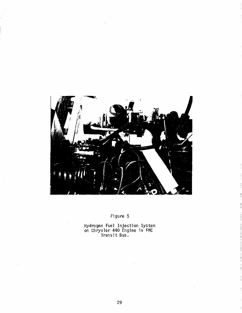
A photograph of the completed installation of the fuel injection equipment
on the engine appears in Figure 5.
5.3 Turbocharger and Other Engine Modifications
As in the case of the test engine, a turbocharger was added to improve the
engine power output. A Rotomaster T0-4 series unit was used, appropriately
sized for this larger engine. The right side exhaust manifold was modified to
mount the turbocharger, and the left and right exhaust manifolds were connected
via a cross-under exhaust pipe. A Rotomaster BPR wastegate was used, and its
setting was determined during actual vehicle testing later.
14

There was insufficient room in the engine compartment for a charge air
cooler, but some provision for stabilization of the intake manifold temperature
was provided. The internal exhaust heating passages in the intake manifold
were blocked off, and water was circulated through these passages via an
electric water pump and an external heat exchanger which is mounted in the
previous location of the air conditioning heat exchanger in the engine
compartment. This probably has only a small effec~ on charge air temperature
rise during high boost operation.
Surface gap spark plugs in conjunction with a capacitive discharge
ignition system were used.
A dual idler pulley was installed to reroute the fan and waterpump drive
pulleys in order to provide room for the rotary valve, which is driven via a
timing belt from the crankshaft. A throttle linkage was fabricated to
interface the hydrogen metering unit. The existing air cleaner was retained,
and adaptors were made to connect it to the metering unit through a four-inch
diameter flex hose. Numerous other modifications to the engine and drivetrain
were required during the course of this work.
5.4 Hydrogen Fuel Storage System and Regulation Components
Nine K type high pressure cylinders were used for on-board hydrogen
storage. Each has a storage capability of approximately 0.45 Kg. (1.0 lb.) of
hydrogen at 13.8 MPa (2000 psig), STP conditions. The total hydrogen storage
capability is therefore 4.1 Kg. (9.0 lbs.) The hydrogen consumption rate
during typical bus service was estimated to be approximately 3.6 Kg. (8 lbs.)
per hour, so that this capacity would probably provide a one hour operational
range for the bus under most circustances.
No exterior areas were available for mounting the cylinders, so that it
was necessary to mount them in the interior of the bus, under a false floor in
15

2
the midsection of the chassis. A semi-hermetic enclosure was constructed of 111
plywood around the cylinders. The cylinders were rigidly mounted in two braces
11of angle iron. Vents were provided on both sides of the enclosure,
connected to outside air. All wood surfaces of both the enclosure and the
original plywood bus floor were treated with a fire retardant and sealed with a
latex based paint. The top of the enclosure forms a false floor on which the
original floor linoleum and bus seats are mounted.
The nine cylinders are connected to a common manifold fabricated of 2.5 em
(1.0 in.) diameter thickwall steel tube. Each cylinder is connected via a
braided stainless steel reinforced, teflon cored high pressure flex line.
Individual shutoff valves at each tank are provided. Access to these valves is
provided by a swing-up type door at the rear section of the cylinder enclosure.
Hydrogen at cylinder pressure flows from the manifold to a high pressure
two-way ball valve. This is intended to be the main manual shut-off valve for
the system. When the valve is open, hydrogen cylinder pressure is connected
with a high flow rate primary pressure regulator. It is also connected with a
pressure gauge and a refueling quick-connect fitting through a check valve.
The regulator reduces the hydrogen pressure to 345 KPa (50 psig), which is the
operating pressure of the fuel injection system. All of the above mentioned
components are located within the cylinder enclosure, and are accessible
through the left-hand side vent, which swings open for access to the refueling
quick connect fitting and the manual shutoff valve.
At 345 KPa (50 psi.) pressure, hydrogen 1eaves the cylinder enclosure
through a 0. 95 em. (3/8 11 ) copper tube which terminated in the engine
compartment. All contact surfaces of the copper tube are isolated from
abrasion by lengths of neoprene hose used as grommets.
16

The main system solenoid valve is located on the firewall of the engine
compartment attached to a shock isolated aluminum plate on which the system
control electronics are also mounted. When the solenoid valve is open,
hydrogen flows through a reinforced neoprene (2.8 MPa rated) hose to the fuel
metering unit on the engine.
Substantial safety factors have been applied in the selection of all the
hydrogen pressure carrying components of the system. Particular attention was
paid to the avoidance of deleterious vibration effects on system components and
pressure lines. Component selection was often based upon previous personal
experience with a given component in vehicular hydrogen service.
5.5 Electronic Safety Control System and Instrumentation
Both the ignition system of the engine and the hydrogen solenoid valve are
actuated only upon the command of an electronic control unit which responds to
several engine and control inputs. This unit and its associated control relays
are mounted on the aluminum plate with the solenoid valve, located on the left
firewall in the engine compartment.
A flammable gas detector is located inside the hydrogen tank enclosure.
It is sensitive to very minute levels of hydrogen, well below the flammability
limit of hydrogen in air. It provides an audible warning of hydrogen leakage
which can be heard from outside the bus through the enclosure vents. Because
the enclosure is sealed to the bus interior, its warning tone is barely audible
inside the bus. A ye 11 ow pi 1 ot 1 i ght is 1 ocated on the dashboard of the bus
which indicates the warning of the gas detector in a manner visible to the
operator. It is felt that this warning method is less likely to cause a
possible panic reaction by bus passengers in the event of a fuel system leak.
The operation of the e 1 ectroni c safety control system can now be
described. It is the primary function of this system to allow hydrogen to flow
17

to the fuel injection system only when it is absolutely safe to do so. A
toggle switch is located on the dashboard above the ignition key switch. When
this toggle switch is on, the control system is enabled.
To start the engine, it is necessary to first turn on the toggle switch,
and then start the engine with the ignition key.
A b 1 ue pi 1 ot 1 i ght on the dashboard indicates whenever the hydrogen
solenoid valve is open. The valve will not open (and therefore the blue light
will not activate) until the engine starter has been engaged and the engine is
cranking. Once the engine has started, the blue light will remain on. If any
problem should occur which would cause the engine to stall, the hydrogen
solenoid valve will automatically shut off. If a hydrogen leak is detected by
the gas detector, the hydrogen solenoid valve will also shut off immediately.
(The blue light will go out, the yellow light will turn on.)
The shut down of a hydrogen engine requires a specific procedure to avoid
the accumulation of unburned hydrogen in the exhaust system of the vehicle.
(This hydrogen is ignited when the engine is started again resulting in a loud
exhaust afterfire.) The electronic control system accomplishes this sequence
automatically regardless of whether the ignition key or the toggle swith is
turned off first. When either is turned off, the hydrogen solenoid valve is
immediately shut off. The ignition system remains on until the engine rotation
has completely stopped. It then is turned off automatically. This sequence
assures that any hydrogen de1 i vered to the engine is combus ted rather than
passed through it unburned, which could occur if the ignition is turned off
prior to hydrogen shutoff in hydrogen engines not using this electronic safety
system.
18

The control system is failsafe in the sense that an electric power failure
also causes the closure of the hydrogen solenoid valve. A diagram of the
entire hydrogen fuel system and electronic safety control system appears in
Figure 6.
Instrumentation is provided on the dashboard to monitor intake manifold
pressure, and exhaust pressure and temperature. These are labeled accordingly.
An electronic bargraph type readout is installed in the lower left dash
area. This provides an indication of hydrogen fuel pressure in the tanks
whenever the manual shutoff valve is open. The gauge is activated whenever the
system is enabled (toggle switch on). The transducer for this remote pressure
sensing system is mounted in a high pressure port of the regulator, located
within the cylinder enclosure.
It is important that at no time is the exhaust pressure allowed to exceed
138 KPa (20 psig). Pressures in excess of this could be destructive to the
engine and turbocharger, or could lead to engine overheating to the point of
backfiring. The vehicle operator should constantly observe the exhaust
pressure gauge to avoid this condition.
6. OPERATIONAL TEST RESULTS
Approximately two hours of vehicle operation have been completed in order
to debug, adjust and test the injection system, fuel system, and all vehicle
components. In addition, preliminary tests were performed on the engine prior
to installation in the bus, and on the fuel storage system to assure against
any leakage.
The fuel injection system and ignition timing were set up on the engine
prior to installation in the bus. The fuel metering unit is set to deliver a
fairly lean misture at idle and low load (0=0.5) but becomes increasingly rich
as· air intake flowrates become greater (maximum 0=0.9). With this calibration
19

of the injection system, the fuel-air mixture remains fairly lean during light
engine loads representative of typical city driving. Under these conditions,
virtually no NOx emissions are produced and the exhaust is essentially
pollution free (except for lube oil pyrolysis). When maximum power is
demanded, the richer mixtures are available, with a sacrifice in emissions.
Detectable NOx emissions are usually encounted for 0 > 0.7.
Ignition timing was set static at 20°BTC. This is considered a compromise
dictated by budgetary constraints which prohibited further engine optimization.
The actual timing range requirement and control function for this
injection-engine combination could be quite broad and complex.
Under high load, high RPM conditions, the wastegate exhibited a
oscillatory characteristic in which it would sequentially open and close at an
approximate one cycle per second rate. This occurred regardless of the
wastegate pressure setting. The only resolution to this problem was the
disablement of the wastegate by restriction of the manifold pressure connection
line. In its present configuration, the turbocharger is working in a
non-wastegated mode. A maximum of 83 KPa (12 psi) boost pressure is generated
at approximately 2700 RPM. This is an ideal boost schedule for this vehicle
since the automatic transmission rarely allows the engine to exceed 3000 RPM in
city driving. However, as previously mentioned, the operator must pay careful
attention to the exhaust pressure to avoid dangerously high levels (above
138 KPa or 20 psi).
The bus was found to exhibit acceleration capability similar to, and
possibly exceeding that of a standard gasoline operated FMC bus, although this
evaluation fs purely a qualitative one. The bus tends to move slowly from a
dead stop due to the lean idle injection setting and lack of turbocharge boost.
Once the road speed has exceeded approximately 15 mph, the fuel-air ratio
20

becomes richer and boost becomes available. A dramatic increase in
acceleration ability is noticed.
Fuel consumption rate and vehicle range were found to match initial design
predictions very closely. Approximately 6.4 Kg (14 lbs.) of hydrogen were used
in the two hours of vehicle testing. This is within the 3.6 Kg/hr (8 lb/hr)
predicted usage rate, although the test service schedule was probably less
strenuous than actual fully loaded passenger service. It is tentatively
concluded that a one-hour vehicle operational range is realizable.
It was observed that under very high engine vacuum conditions, oil smoke
appears in the exhaust. A brief burst of smoke is sometimes observed during
rapid engine decelleration transients. The source of this smoke is believed to
be either oil leakage through the turbocharger compressor seal, or oil suction
past the piston rings since the engine was just rebuilt and the rings are not
yet seated.
An accumulation of dirt particles in the metering orifice of the regulator
caused a leak-through condition in the regulator which caused a release of
hydrogen into the cylinder enclosure through the regulator safety relief valve.
The engine had just been shut off prior to this occurrence. The hydrogen
detector responded immediately, and the main shut-off valve was turned off to
stop the flow. Cleaning of the regulator orifice rectified the problem. It is
believed that the grit entered the system during a refueling operation. The
refueling quick-connect fitting had accumulated road dirt which was inducted
into the fuel system during refueling. Since this occurrence, the opening of
the quick connect fitting has been sealed with tape to prevent dirt intrusion.
The incident has not occurred again.
In its present configuration, the fuel system does not contain a filter
since only clean, tanked hydrogen was to be used. It is recommended that a
21

high pressure, fine mesh filter be inserted between the refueling fitting and
the check valve to further assure against this occurrence. A further
improvement recommended is the insertion of a high pressure solenoid valve in
series with the manual shut off valve. This should be actuated by parallel
e 1 ectri ca 1 connection with the hydrogen so 1 enoi d va1ve in the engine
compartment, although an electrical override switch should be provided since
this valve would have to be open to permit refueling. This valve would provide
additional protection in the event of catastrophic failure of the regulator,
check valve, pressure transducer or pressure gauge.
It is felt that the most important observation was that under no
conditions was intake backfiring observed. This represents a significant step
in hydrogen engine technology since all previous hydrogen fueled vehicles
(buses or otherwise) have been plagued with this problem despite such methods
as water injection, exhaust gas recirculation, improved carburetors and other
techniques. The successful backfire-free operation of this bus has provided
verification of the effectiveness of timed fuel injection in eliminating
hydrogen engine backfiring.
22

7. REFERENCES
1. MacCarley, C.A. Hydrogen Fuel Applications for Urban Transit, Proc. Society and Aerospace Teclmologg Workshop, American Institute of Aeronautics and Astronautics, Los Angeles, California, 1979.
2. Norman, J.H., K.J. Mysels, D.R. O'Keefe, S.A. Stowell and D.G. Williamson. Chemical Studies on the General Atomic Sulphur-Iodine Thermochemical Water Splitting Cycle, Proc. Second World Hydrogen Energg Conference. Zurich, Switzerland, 1978.
3. Hadden, L.D. The Economics of Producing Hydrogen From a Small Air Blown Coal Gasifier, Proc. Second World Hydrogen Energg Conference. Zurich, Switzerland, 1978.
4. Ihara, S. On the Study of Hydrogen Production from Water Using Solar Thermal Energy, Proc. Second World Hydrogen Energg Conference. Zurich, Switzerland, 1978.
5. Nozik, A.J. Hydrogen Generation Via Photoelectrolysis of Water: Recent advances, Proc. Second World Hydrogen Energg Conference. Zurich, Switzerland, 1978.
6. Fernandes, R.A. Hydrogen Cycle Peak-Shaving for Electric Utilities, Proc. Ninth Intersociety Energg Conversion Engineering Conference. San Francisco, August 1974.
7. Burger, J.M. and P.A. Lewis, R.J. Isler, and F.J. Salzano. Energy Storage for Uti 1iti es vi a Hydrogen Systems, Proc. Ninth Intersociety Energg Conversion Engineering Conference. San Francisco, August 1974.
8. King, R.O., J. Durand, B.D. Wood, and A.B. Allan, The Oxidation, Ignition, and De tonation of Fue 1 Vapors and Gases, XIV. Canadian Journal of Research, Vol. 28, Sec. F., 1950.
9. Obert, E. F. Internal Combustion Engines, 3rd Ed., International Textbook Co., Scranton, Penn., 1968, pp. 314-316.
10. Adt, R.A. and M.R. Swain. Hydrogen Engine Performance Analysis Project, Quarterly Report, March 1977, University of Miami, Coral Gables, FL.
11. Watson, H.C. and E. E. Milkins. Some Problems and Benefits From the Hydrogen Fueled Spark Ignition Engine, SAE paper #789212, 1978.
12. MacCarley, C.A. and W.O. VanVorst. Electronic Fuel Injection Techniques for Hydrogen Powered I. C. Engines, Int. J. Hydrogen Energg, Vo 1. 5, pp. 179-203, Int. Association for Hydrogen Energy, Coral Gables, FL, 1980.
13. MacCarley, C.A. A Study of Factors Influencing Thermally Induced Backfiring in Hydrogen Fueled Engines, and Methods for Backfire Control, Proc. Intersociety Energg Conversion Engineering Conference, American Sociaty of Mechanical Engineers, Atlanta, Georgia, 1981.
23

CH4 C3R8~ Gasoline
Minimum Ignition Energy (mJ) 0.02 0.28 0.25 (0.25)a
Ignition Temperature (OX)b 858 810 783 530
Adiabatic Flame Temperature (OK)b 2384 2227 2268 (2270)
Fla~bility Limits (% iu air) 4.0-75 5.3-15 2.2-9.5 1.5-7.6
Laminar Flame Velocity (cm/sec)b 190 38 40 (~30)
2Diffusivity (em /sec) 0.63 0.20 (0.08)
Minimum Quenching Distance (em) 0.06 0.25 0.19
Normalized Flame Emissivity0 1.00 1.7 1.7 1.7
aQuantities in parentheses are estimates.
bData for stoichiometric air-fuel mixtures.
Table 1. HYDROGEN COMBUSTION CHARACTERISTICS COMPARED WITH OTHER COMMON FUELS
HYDROGEN SOURCE DENSITY OF STORAGE* CONSIDERATIONS AND lbs. H2/ft. 3 LIMITATIONS
Compressed hydrogen gas (2,000 psig) 0.650 Requires gas compression for storage
Liquid hydrogen (20°K) 4.48 Requires gas liquefaction for storage
Fe- Ti hydride 3.30 (0.9 wt.%) Mass of system
Mg-Al hydride 3.36 (6.0 wt.%) Insufficient engine waste heat for use of this hydride alone
Partial decomposition of hydrocarbons Varies On-board hydrogen generation equipment required
7.84** Chemical Expense
15.59*x Dangerous to handle
~volume of containment vessel not included """N'ater not i nc 1uded
Table 2. COMPARISON OF AVAILABLE ON-BOARD HYDROGEN STORAGE TECHNIQUES
24

FUEL METERING UNIT (Component 1 for)
GASEOUS FUEL INJECTION TECHNIQUE INCORPORATING AIR FLOW CONTROLLED FUEL METERING.
VACUUM CHAMBER
UPPER CHAMBER
MODIFIED SU CARBURETOR BODY
~I:...:...R_-+-OUTLET
l FUEL METERING VALVE ASSY.
RETURN SPRING
PULSATION DAMPENER PISTON
INLET
SEAL"o" RING
ADJUSTMENT SET SCREW ___., lili!lki~IIRJ TAPERED METERING PIN B
FUEL OUTLET
-•--- FUEL METERING VALVE ASSY.
--r--........- FUEL INLET
4" _________,..,-!,1FIGURE 1
25

ROTARY VALVE INJECTION DISTRIBUTOR (Component 2 for)
GASEOUS FUEL INJECTION TECHNIQUE INCORPORATING AIR FLOW CONTROLLED FUEL METERING
N O'l
INLET PORT B
.///
/ /
, ~.. .• ..· ' .'
3l __j
16
FIGURE 2

PHANTOM P~AN VIEW OF TYPICAL SYSTEM INSTALLATION OF GASEOUS FUEL INJECTION TECHNIQUE INCORPORATING AIR FLOW CONTROLLED FUEL METERING.
FUEL PRIMARY PRESSURE4 CYLINDER, 4 STROKE REGULATOR
IN AT HIGH.
N ........
I.C. ENGINE
EXHAUST VALVES(4)
ROTARY VALVE
FUEL
FUEL AT CONSTANT PRESSURE l ~30psig)l
_.l.--.&.., PRESS~ ¢:::===::::[]
-- FUEL FLOW
---AIR INTAKE
FUEL METERING UNIT lComponent 1)
INJECTION DISTRIBUTOR (Component 2)
FIGURE 3

90
BHP 80
BMEP (psi)
140- 70
130
120-60
110
100-50
90
f .8-80-40
.7-70
.6-60-30
.5-50
.4-40-20
.3-30
,2...,..20- 10
.1-10
0- 0- QL----_.J._____J_____L______.L,____J____---f
0 1000 2000 3000 RPM
4000 5000
FULL THROTTLE-VARIABLE RPM TEST
FIGURE 4. T: HYDROGEN FUELED 2600 cm3 ,4 cyl, ENGINE USING TIMED PORT INJECTION, TURBOCHARGER, INNER- CHARGE COOLER,
ELECTRONIC IGNITION TIMING CONTROL (Q-30° BTDC)
NA: HYDROGEN FUELED 2600 cm3,4 cyl, ENGINE USING TIMED PORT INJECTION, NATURALLY ASPIRATED, STATIC Tl MING (19°BTDC)
28
,;·~
Figure 5
Hydrogen Fuel Injection System on Chrysler 440 Engine in FMC
Transit Bus.
29

CRANKSHAFT DRIVE PULLEY
DISTRIBUTOR -ROTARY VALVE PULLEY
ROTARY VALVE INJECTION DISTRIBUTION AIR INLET
IGNITION COIL HYDROGEN METERING UNIT
TURBOCHARGER
ENGINE ELECTRONIC CONTROL MODULE
STARTER __;...___,_,
CYLINDER MANIFOLD
9"K"TYPE PRESSURE CYLINDERS
HYDROGEN DETECTOR
FUEL GAGE
~~D- FUEL FLOW INDICATOR
D
HYDROGEN LEAK INDICATOR
CONTROL SYS. ENABLE SWITCH
IGNITION KEY SWITCH
FIGURE 6. HYDROGEN FUEL SYSTEM DIAGRAM FOR TRANSIT BUS
30

Appendix 1
July 1980
Aug.
Sept.
Oct.
Nov.
Dec.
Jan. 1981
Feb.
Mar.
Apr.
May
June
July
Aug.
Sept.
Oct.
Nov.
Dec.
WORK SCHEDULE
RTD H2 Bus ProgramTasks to be Completed by Month End
Injected engine first operated
Refinement and tests of engine Installation of 4 injectors
Vehicle-Engine identified. Planning of actual vehicle and layout. Preliminary draft of vehicle.
Decision on aspiration technique for bus engine. Decision on engine to be used.
Procurement of engine
Dyno setup to be completed of :non-converted engine
Fabrication of aspiration apparatus for engine
Preliminary data generated on engine-aspiration system performance
Refinement and further tests of engine
Redesign of aspiration hardware for high reliability
Probable vehicle delivery. Engine R&R Chasis stripped.
Installation of engine in bus chasis
Installation of H2 fuel system and instrumentation
Bus modification completed
First road tests completed
Repair-Remods where needed
Comprehensive road tests completed
Report written. Manuals written. Vehicle delivered
. 31

Appendix 2
1., .;
i +j_ ~
/
r-~ ~ , ~:-'t~
r--· l
-~ i
... l'
l,
.,
In..
.L.____L
..., ... ~ ~.
I
"
() r, \)
" .1 I ··.. I. I I

Appendix 3
~·
' ~
>
":
~
--
1
I ~ I
~ ~
I (V)..... ' I I
§l"' .....
l
! i I
I I
l i l
.L '!
' 1~ ~ " ~
.....~ I Oo a-.
~. ' \ ~ l.::• "'"' ~"' ~
v ~·
i ~ ~
:::~ '•
'\.I') ' ' ~
V\: i I *'~~ ~ .
~ ~ .... ' ~ ~
t." ~ ' '
'-.!. ~""-~· ) ~
.......... ~
11 0 ) {
~ .. ~ "\
~ ~
~ h~
~ ~ ~
33