final report - lrrb
TRANSCRIPT

2005-28Final Report
Occurrence of Bumps in Overlays

Technical Report Documentation Page 1. Report No. 2. 3. Recipients Accession No. 2005-28 4. Title and Subtitle 5. Report Date
July 2005 6.
Occurrence of Bumps in Overlays
7. Author(s) 8. Performing Organization Report No. W. James Wilde and William Zerfas 9. Performing Organization Name and Address 10. Project/Task/Work Unit No.
11. Contract (C) or Grant (G) No.
Department of Mechanical and Civil Engineering Minnesota State University, Mankato 205 E. Trafton Science Center Mankato, MN 56001
(c) 85056
12. Sponsoring Organization Name and Address 13. Type of Report and Period Covered Final Report 14. Sponsoring Agency Code
Minnesota Department of Transportation Research Services Section 395 John Ireland Boulevard, Mail Stop 330 St. Paul, MN 55155
15. Supplementary Notes
http://www.lrrb.org/pdf/200528.pdf 16. Abstract (Limit: 200 words)
The development of small bumps in the surface of hot-mix asphalt overlays has been a problem for state and local highway agencies for many years. Sometimes these bumps are small and are not large enough to be felt by drivers. Under many conditions, however, they can be large enough to cause ride-related problems at normal operating speeds. Under this project, a survey was conducted of local and state engineers in Minnesota responsible for highway construction and maintenance to compile corrective actions that they have used avoid these bumps and to mitigate their effects if they occur.
Instrumentation sites were incorporated into this project to determine the magnitudes and profiles of temperature in the existing asphalt layer when a new layer of hot asphalt is placed on top of it. The instrumentation sites were also used to gain further information on the common practices of highway construction personnel in reducing the probability of bumps, and mitigation efforts if bumps occur.
This report describes the survey, site visits, construction instrumentation, laboratory studies, and evaluation conducted by the project team. It also presents a draft booklet compiling the common practices for avoiding and mitigating bumps gathered throughout the project. 17. Document Analysis/Descriptors 18. Availability Statement Bituminous overlays Bumps Construction practices
Crack sealant Field instrumentation
No restrictions. Document available from: National Technical Information Services, Springfield, Virginia 22161
19. Security Class (this report) 20. Security Class (this page) 21. No. of Pages 22. Price Unclassified Unclassified 77

Occurrence of Bumps in Overlays
Final Report
Prepared by:
W. James Wilde William Zerfas
Minnesota State University, Mankato
Mn/DOT Office of Materials
July 2005
Published by:
Minnesota Department of Transportation Research Services Section
395 John Ireland Boulevard, Mail Stop 330 Saint Paul, MN 55155
This report represents the results of research conducted by the authors and does not necessarily represent the view or policy of the Minnesota Department of Transportation and/or the Center for Transportation Studies. This report does not contain a standard or specified technique. The authors and the Minnesota Department of Transportation and/or Center for Transportation Studies do not endorse products or manufacturers. Trade or manufacturers’ names appear herein solely because they are considered essential to this report.

Acknowledgements
We would like to thank the Minnesota Local Road Research Board (LRRB) for their support in funding this project, and the many county engineers and construction personnel throughout the State of Minnesota who contributed to the project by providing information, suggestions, current practices, and who helped in many other ways toward the success of this project.
We also would like to express our gratitude to the members of the technical advisory panel who were instrumental in the development of the project and the associated guidelines. The expertise and experience of the panel members were invaluable to the project team throughout the project.
John Brunkhorst, McLeod County Steve Oakey, Mn/DOT District Seven, retired Chris Duininck, Duininck Brothers, Inc. Art Bolland, Mn/DOT District Eight Al Forsberg, Blue Earth County Michael Flaagan, Pennington County
In addition, this project could not have been completed without the expertise and assistance provided by Roger Olson and Jim McGraw at the Mn/DOT Office of Materials.

Table of Contents Chapter 1. Introduction............................................................................................................. 1
Objectives ................................................................................................................................... 1 Scope........................................................................................................................................... 1
Chapter 2. Literature Review.................................................................................................... 3 Chapter 3. Survey of Current Practice...................................................................................... 6
Survey Results ............................................................................................................................ 6 Chapter 4. Project Site Visits.................................................................................................... 9
Pipestone County ........................................................................................................................ 9 Steele County ............................................................................................................................ 11 Douglas County ........................................................................................................................ 12 Todd County ............................................................................................................................. 13 Summary ................................................................................................................................... 15
Chapter 5. Database................................................................................................................ 16 Introduction............................................................................................................................... 16 Database Development ............................................................................................................. 16 Current Status............................................................................................................................ 17 Construction Observations........................................................................................................ 17 Database.................................................................................................................................... 18
Chapter 6. Instrumentation Sites ............................................................................................ 20 Site Selection ............................................................................................................................ 20 Site Instrumentation .................................................................................................................. 22 Overlay Construction Site Summaries...................................................................................... 25 Summary ................................................................................................................................... 40
Chapter 7. Laboratory Testing................................................................................................ 41 Thermal Expansion Testing ...................................................................................................... 41 Laboratory Testing – Office of Materials ................................................................................. 42
Chapter 8. Conclusions and Recommendations ..................................................................... 48 Evaluation of Theories.............................................................................................................. 48 Overview of Remaining Theories............................................................................................. 49 Conclusions............................................................................................................................... 50 Recommendations..................................................................................................................... 51
Appendix A. Survey of Current Practice ................................................................................... A-1 Appendix B. Bump Avoidance Booklet

List of Figures
Figure 4.1. Transverse crack with overlay-related bump – Pipestone County. ........................... 10 Figure 4.2. Several consecutive overlay-related bumps – Pipestone County. ............................. 10 Figure 4.3. Straightedge showing effect of bump in pavement profile. ...................................... 11 Figure 4.4. Cutaway section at pavement edge showing crack sealant at interface – Pipestone
County. .................................................................................................................................. 11 Figure 4.5. Routed and sealed crack, no overlay, Todd County. ................................................. 14 Figure 6.1. Close up photograph of thermocouple installation.................................................... 23 Figure 6.2. Instrumentation installation after placement of first lane.......................................... 24 Figure 6.3. Impact of installation on construction activities........................................................ 24 Figure 6.4. Temperature variations near milepost 34 on TH 22, Mn/DOT District 7. ................ 26 Figure 6.5. Temperature variations near milepost 19 on TH 22, Mn/DOT District 7. ................ 26 Figure 6.6. One of numerous small bumps found near milepost 34 on TH 22 near Mapleton,
Minn....................................................................................................................................... 27 Figure 6.7. A Large bump near milepost 19 on TH 22 near Wells, Minn................................... 27 Figure 6.8. Core removed from pavement near milepost 34 on TH 22. ...................................... 28 Figure 6.9. Temperature variations, CSAH 9, Lyon County. ...................................................... 29 Figure 6.10. Bump at sealed crack on CSAH 9 in Lyon County................................................. 30 Figure 6.11. Bump at sealed crack on CSAH 9 in Lyon County................................................. 30 Figure 6.12. Bump at Sealed Crack at Lyon County CSAH 9. ................................................... 31 Figure 6.13. Core extracted from station 17+00 at the overlay project in Lyon County............. 32 Figure 6.14. Core extracted from station 20+00 at the overlay project in Lyon County............. 33 Figure 6.15. Bumps in 200-foot section in Cottonwood County. ................................................ 36 Figure 6.16. Temperature data from tight-blade leveling operation on County Road 9, Douglas
County. .................................................................................................................................. 38 Figure 6.17. Bumps in overlay on US 212 in District 8. ............................................................. 39 Figure 6.18. Paver-laid thin-lift overlay on US 212. ................................................................... 40 Figure 7.1. Strain sweep results. .................................................................................................. 44 Figure 7.2. Sealant master curves. ............................................................................................... 45 Figure 7.3. Field sample creep results of 3723 material. ............................................................. 46 Figure 7.4. Creep comparison of 3723 and 3725 field samples................................................... 47

List of Tables Table 3.1. Effectiveness of actions reported by survey respondents. ............................................ 7 Table 3.2. Cost-effectiveness of pretreatments as noted by respondents. ..................................... 7 Table 3.3. Factors affecting pretreatment strategy......................................................................... 8 Table 6.1. Summary information from instrumentation and observation sites............................ 21 Table 6.2. Additional information from instrumentation and observation sites. ......................... 21 Table 6.3. Crack opening data for CSAH 9, Lyon County.......................................................... 34 Table 7.1. Relative stiffness of selected sealant materials........................................................... 44

Executive Summary The development of small bumps in the surface of hot-mix asphalt overlays has been a problem for state and local highway agencies for many years. Sometimes these bumps are small and are not large enough to be felt by drivers. Under many conditions, however, they can be large enough to cause ride-related problems at normal operating speeds. In cases where a two-lift overlay is placed, bumps may show in the first lift but not in the second. The problem of bumps in overlays is most pronounced in roadways where a single lift is placed. Any bumps that form are often left to be beaten down by traffic, which results in an uneven surface and in many cases no significant reduction in the size or severity of the bump. Initially, a survey was conducted of local and state engineers in Minnesota responsible for highway construction and maintenance to compile their thoughts and suggestions regarding the causes of bumps in overlays and the corrective actions that can be taken to mitigate their effects if they occur. The information gathered from the survey was used in organizing instrumentation sites and individual interview visits with some of the survey respondents. Instrumentation sites were incorporated into this project to determine the temperature magnitudes and profiles in the existing asphalt layer when a new layer of hot asphalt is placed on top of it. These temperature profiles were used in determining the laboratory testing temperatures of crack sealant material. The instrumentation sites were also used to gain further information on the common practices of highway design and construction personnel in reducing the probability of bumps, and mitigation efforts if bumps occur. This project investigated several theories regarding the causes of bumps in overlays, and determined that three were likely to be invalid given the evidence found in this project. These were
• that the crack sealant expanded due to temperature, • that water trapped in the crack turned to steam, and • that the cracks closed when the existing surface expands
Under this project, however, other theories were not able to be evaluated, due to the scope of the project. This report describes the survey, site visits, construction instrumentation, laboratory studies, and evaluation conducted by the project team. It then presents analysis of the data and information gathered, and reasons why the project team considers the three theories evaluated to be unlikely to cause bumps in overlays. Finally, in Appendix B, a draft booklet is presented to disseminate the information collected on common practices for avoiding and mitigating bumps.

1
Chapter 1. INTRODUCTION The development of small bumps in the surface of hot-mix asphalt (HMA) overlays has been a problem for state and local highway agencies for many years. Bumps in overlays occur near or directly above cracks in the existing pavement surface. In almost all cases, these bumps are related to cracks that have been previously sealed. Sometimes these bumps are small and are not large enough to be felt by drivers. Under many conditions, however, they can be large enough to cause ride-related problems at normal operating speeds. In cases where a two-lift overlay is placed, bumps may show in the first lift but not in the second. The problem of bumps in overlays is most pronounced in roadways where a single lift is placed. Any bumps that form are often left to be beaten down by traffic, which results in an uneven surface and in many cases no significant reduction in the size or severity of the bump. Many theories have been promoted to explain the cause of these bumps. They range from thermal expansion to slipping and sticking to compression and rebound of the sealant material. Some of these theories were evaluated as part of this project, and others were identified during the course of the interviews and site visits conducted by the project team. A survey was conducted of local and state engineers in Minnesota responsible for highway construction and maintenance to compile their thoughts and suggestions regarding the causes of bumps in overlays and the corrective actions that can be taken to mitigate their effects if they occur. This report describes the survey, site visits, construction instrumentation, laboratory studies, and evaluation conducted by the project team.
Objectives The two major objectives of this project were to study the cause and effect between the sealed bituminous cracks and the formation of bumps in HMA overlays during the overlay placement and compaction process, and to develop a guidelines manual for engineers faced with this problem. The guidelines manual developed as part of this project is not intended to be a “best practices” manual or a set of “recommended practices” by the Minnesota Department of Transportation (Mn/DOT). Rather, the guidelines presented in Appendix B of this report are a collection of common practices in use by city and county engineers throughout the State of Minnesota. These are practices that are endorsed by the individuals who suggested them, and not the Local Road Research Board (LRRB) or Mn/DOT.
Scope This report presents the information gathered by the project team and identifies the hypotheses gathered prior to and during the course of the project. The scope of the project included the following:

2
• Develop and distribute a survey to state, county and city engineers regarding their experiences with bumps in overlays.
• Conduct site visits of projects that have experienced such bumps and gather background information on those sites.
• Identify sites scheduled for an overlay with a potential for bumps and design instrumentation for these sites.
• Conduct field instrumentation of up to four sites around the state. • Conduct lab testing on samples from the sites with the bumps. • Perform laboratory studies on sealant products to investigate materials properties. • Monitor the selected sites one year after overlay to document pavement condition.
The project was originally intended to investigate the leading hypothesis at the time – that thermal expansion of the crack sealant led to the formation of bumps. As the project progressed, however, it became apparent that this hypothesis did not reflect the true mechanism of bump formation. The hypotheses that were proposed by those interviewed by the project staff included the following.
• Thermal expansion of crack sealant material • Moisture under existing layers turning to steam • Closure of cracks at high temperature • Sliding of overlay material • Sticking of overlay material • Low-density material in area of cracks • Compression and subsequent expansion of sealant material
Although the initial scope of the project was to investigate the thermal expansion hypothesis, others were investigated after it was eliminated. Further research should be conducted in order to identify the true cause of the bumps. The information presented in this report relating to these other hypotheses is simply based on observations at construction sites and on discussions with the project team and others interviewed by the team.

3
Chapter 2. LITERATURE REVIEW As the literature review was conducted for this project, it was found that very little information exists regarding existing research on the formation of bumps in overlays. Of the documents found while conducting the literature review, two are from a manufacturer of crack sealant products, one is from an industry organization, four are from state highway agencies (of which one is an ongoing project) and two are from national research agencies. Most of the articles and reports focus on the prevention and mitigation of the bump problem in overlays. Overlay Bump Investigation, North Carolina Department of Transportation Memorandum, Thomas M. Hearne, 2004. In 2004, Mr. Tom Hearne investigated overlay bumps related to crack sealants in several projects in North Carolina. This memorandum describes a small investigation into the physical properties of crack sealants used in the particular construction projects. The investigation addressed the temperature effects on these properties, and addressed several of the same theories as the current project, but to a lesser extent. It is interesting to note, however, that the small investigation conducted in North Carolina confirms some of the conclusions made in the current report. This memo listed several factors “thought to enhance the formation of bumps”. These include wide transverse cracks, deep sealant reservoir, incompressible material directly under sealant, fine-graded low-stability asphalt mix rich in asphalt cement, and rolling too soon after placement. Many of these factors are addressed in the common practices guidelines in Appendix B. Bumps In Overlays Don't Have To Happen, Crafco Incorporated, Chandler, AZ, 1995. This article is an informational paper on Crafco's recommended policy on preventing bumps during an overlay. It mentions two potential causes – too much sealant expands as it warms, and compaction equipment slips over the sealant material. It provides some precautionary steps to avoid the problem, including: minimize overbanding, rout cracks when sealing them, place crack sealant slightly below the surface of the pavement, avoid vibratory rollers on the first pass, and place clean, dry concrete sand over any squeegeed sealant. The article also suggests conducting crack sealing 6 – 12 months prior to an overlay. Use of Crack Sealing Prior to Placement of Hot Mix Asphalt, Flexible Pavements of Ohio, Technical Bulletin, Columbus, OH. This article, published by the asphalt industry as an aid in preventing overlay bumps, addresses many of the common theories considered to be the cause of the bumps. It mentions HMA sliding on the crack sealant, the difference in the melting point of the materials, and friction between the two materials. It suggests the following as potential contributory factors: amount of overbanding, amount of sealant, age of sealant, thermal expansion of the sealant, thickness of the overlay (also a preventive factor), and direction of travel of the compaction equipment. The article mentions thicker overlays, polymer-modified asphalt, fabrics and interlayers, and saw and seal operations as treatments for preventing the bumps. If crack sealing is done, the article recommends that it be done at least one year prior to the overlay, and that excessive crack sealing should be avoided. The article also gives recommendations specific to Ohio specifications and sealant types, regarding when different types should be used.

4
Bump Formation and Prevention in Asphalt Concrete Overlays which have been Crack Sealed, Crafco, Inc., Chandler, AZ. This article is the most direct treatment of the bump problem of all the literature found in this review. It describes the method of bump formation, describes factors in the formation of the bumps, and proposes methods to avoid the formation of bumps. As factors in the development of the bumps, the article mentions mixtures with high frictional properties, higher mix temperatures, roller speed and pattern, number of roller passes, type of roller, and stiffness of tack coat. Performance and Selection of Pavement Crack Sealant Under Nevada Conditions and Before Overlays The state of Neveda is conducting a research effort to evaluate several problems with crack sealing in the state. One objective of the research is to evaluate crack sealant regarding their probability in causing the overlay bumps that have been observed in Minnesota. The research will also attempt to determine to what extent the thermal expansion of crack sealants affects the formation of bumps, and to evaluate the long-term effects of those crack sealants that do not cause the bumps. Crack Seal Application, Pavement Preservation Checklist Series, Publication No. FHWA-IF-02-005, Federal Highway Administration, Washington, DC, 2001. This small pocket guide mentions bumps in overlays as a problem and provides potential solutions. Such solutions include sealing at least one year prior to overlay placement, using a stiffer tack coat, proper selection of rollers, and minimizing the amount of crack sealant material at the surface. Johnson, A.M., Best Practices Handbook on Asphalt Pavement Maintenance, Report No. MN/RC-2000-04, Minnesota Department of Transportation, St. Paul, 2000. This report presents background information on pavement maintenance techniques and the importance of preventive maintenance in a pavement preservation program. It highlights the distinction between preventive maintenance and rehabilitation, and stays within the realm of maintenance. In the section on crack treatments, it describes the difference between crack sealing and filling, and discusses the materials and methods appropriate for each. In a table entitled “Effective Crack Sealing Tips” the report makes mention of the potential problem with bumps in overlays, the report states: “Crack sealing is recommended 6-12 months prior to an overlay. To eliminate bumps in overlays caused by too much sealant or roller slippage, use proper sealant application procedures and roller techniques.” Tons, E., and V.J. Roggeveen, Laboratory Testing of Materials for Sealing Cracks in Bituminous Concrete Pavements, Highway Research Abstracts, Vol. 25, No. 8, Highway Research Board, Washington, DC, 1955. While it is recognized that much technological advance has been made since this paper was published in 1955, most of the results of this research are applicable today, including that crack sealants should not change their properties in hot weather, and that the sealant should not extrude from the crack or become tacky on its exposed surface during periods of high temperature. This paper mentions the possibility for thermal expansion of the crack sealant, and states that this is an undesirable property of the material.

5
Belangie, M.C., and D.I. Anderson, Evaluation of Flexible Pavement Crack Sealing Methods Used in Utah, UDOT-MR-81-1, Utah Department of Transportation, Salt Lake City, 1981. This report details an evaluation of various crack sealants used in Utah. The evaluation found that routing and sealing cracks and presawing (sawing and sealing) were the most promising methods for the conditions present in their evaluation at that time. Because of this lack of information in the literature on this subject, the project team proposed to conduct a survey of current practice among engineers in Minnesota. The results of this survey are discussed in the next chapter.

6
Chapter 3. SURVEY OF CURRENT PRACTICE This chapter describes the development, distribution and analysis of a survey of all county and some city engineers within the State of Minnesota. The objectives of the survey was to identify potential sources of information for future interview and/or instrumentation site visits, and to identify methods and materials used by these engineers to minimize and mitigate the occurrence of bumps in their overlays. This chapter includes a summary of the responses received. Appendix A includes a blank survey that was sent to the engineers.
Survey Results Of the 87 county engineers and a few select city engineers surveyed, 19 were returned. The agencies returning the surveys include:
Benton County Marshall County Beltrami County McLeod County Blue Earth County Morrison County Chippewa County Pennington County City of Chanhassen Pipestone County City of Moorhead Rock County Clay County Steele County Cook County Todd County Douglas County Winona County Goodhue County
Observations Of the 19 responses received, 10 of the agencies had observed the problem, and one has not performed any overlays in the past 10 years. Of the 10 agencies where the bump problem has occurred, all but one had observed the problem on overlays between 1.5 and 2 inches thick. The tenth agency observed the problem on an overlay which varied in thickness from 3 to 4.5 inches. One observation was made that the bump problem seemed to occur when “rubberized crack filler had been used” in the cracks and joints.
Actions Taken to Mitigate Bumps Many of the agencies have avoided the problem by either increasing the thickness of the overlay or by modifying the rolling pattern for compaction. Others have set a policy of not patching cracks within one year of overlaying. Those that have modified the rolling pattern noted that by doing so, they effectively lower the mix temperature during compaction, which can also result in lower density. The modified rolling patterns mentioned include simply letting the mix cool before rolling, and reducing the amount of rolling. Other suggestions include tight blading with a grader and using the first, thin lift as an “insulator” layer. In this case, the first lift was allowed to cool completely, sometimes up to five days prior to allowing the contractor to place the final lift.

7
Effectiveness of the Actions Taken Table 3.1 shows comments from the survey respondents indicating the effectiveness of the steps they had taken to mitigate the problem.
Action Effectiveness / Reaction Increased thickness Improvement Reduce rolling Improvement, but more mix required, and
density compromised Lower mix temp Somewhat effective, but did not get
required density ½-inch thick leveling course
Eliminated bumps after placement of 2 inch mat
Insulating 1st lift Resolved problem Hold rollers back Significant improvement Patch and seal >1 yr prior Improvement
Table 3.1. Effectiveness of actions reported by survey respondents.
Cost-Effectiveness of Pretreatments This section of the survey asked respondents to identify the most cost-effective pretreatment techniques that they have used. In Table 3.2, each of the pretreatments identified were categorized as H, M, or L, for highly, moderately, or less cost effective. In the Cost-Effectiveness column, each level of effectiveness is also given a number corresponding to the number of responses indicating that level.
Pretreatment Cost-Effectiveness Sweep / Air Blast H – 1 Mill H – 1 Mill and Clean Joints / Cracks H – 1 Hand Patch M – 1 Blow Patch Fabric / Geotextile Thin-lift Leveling – Paver Laid L – 1 Tight Blade Leveling H – 3, M – 1, L – 1 Slurry Seal Micro-Surfacing Stress Relief Hot Mix
Table 3.2. Cost-effectiveness of pretreatments as noted by respondents.
Factors Affecting Pretreatment Strategy The factors that may affect the pretreatment strategy included type and age of pavement, traffic volume, and type and age of crack sealant. Respondents were asked if any of these play a role in affecting the strategy selected. The response and the number of similar responses given are shown in Table 3.3.

8
Factor Affect Selection of Strategy? Type of Pavement Y – 2, N – 4 Age of Pavement Y – 3, N – 3 Volume of Traffic Y – 3, N – 3 Age of Sealant Y – 1, N – 5 Type of Sealant Y – 2, N – 3
Table 3.3. Factors affecting pretreatment strategy. One comment made under “Type of Sealant” was that the particular county removes any rubber sealant before an overlay is placed. The most cost-effective strategies were indicated to be the following:
• Tight blade leveling • Rout and fill joints • Thin lift overlay, and hand patch ahead of paver • Blow patch, seal coat
The most successful (as opposed to most cost-effective) pretreatments included the following:
• Rout and seal • Mill and fill • Thin lift overlay • Leveling course • Let crack sealant age one or more years
The least successful pretreatments included the following:
• “the old AC-3 oil” • blow patch • the “do nothing alternative”
Potential Instrumentation Projects Six agencies indicated that they had upcoming projects that may be a candidate for this problem, and indicated that they would be willing to work with the project team to observe and instrument an overlay construction project. These agencies were contacted to begin coordination for the observation and instrumentation of a few of these projects. Eventually, instrumentation sites were established at Jackson, Lyon, and Douglas counties, as well as in Mn/DOT District Seven.

9
Chapter 4. PROJECT SITE VISITS This summary report describes the visits that the project team (Dr. Wilde and Mr. Zerfas) made to four counties that have had experience with the overlay bump problem: Pipestone, Steele, Douglas, and Todd Counties. This chapter includes a summary of these meetings, pictures from some of the projects the team observed – both those that experienced the problem and those that did not, and other information received from the counties.
Pipestone County The project team visited Pipestone County and met with David Halbersma, County Engineer for Pipestone County to discuss the Overlay Bumps project. Mr. Halbersma discussed a recent project where significant overlay bumps occurred - CSAH 8 in Pipestone County. The project included a 1½-inch overlay, paved in 2002. The last overlay was 2½ inches in 1988 and the original pavement was 1½ inches thick. The HMA design followed the Marshall Method per Mn/DOT 2350 specification. The transverse cracks in the first two miles of the existing pavement had been sealed. Mr. Halbersma remembers them having a wide overband and believes that the Crafco 515 sealant was used. (Roadsaver 515, Mn/DOT 3723). All cracks were routed and sealed in 1995. Surface preparation included tack coat prior to overlay. The contractor arrived in the afternoon to begin paving. The temperature that day was hot, in the 90s F, with little to no wind or clouds. The bumps occurred quickly once breakdown rolling began. The HMA mix temperatures were about 300° F. The more they rolled, the worse the problem became. The bump area was about 12 inches in width (in the longitudinal direction of the roadway), centered over the transverse crack. The next morning, the contractor lowered the temperature of the HMA arriving on site to 260° F and the county asked to have the breakdown roller wait for the mat to cool even further. Due to this request, the county waived the density requirements in the specification. Few bumps arose during the overlay construction. The county engineer discussed his ideas regarding the occurrence of bumps on this project. He felt that the relatively high temperature (ambient air, pavement, and HMA) caused the sealant to bubble, or expand, and push the sealant upwards into the HMA. When action was taken to reduce temperatures, problems tended not to arise. He also felt that the wide overband affects the probability of bumping due to the increase in contact area between the HMA and sealant material. Pipestone County now attempts to avoid bumps by taking several steps. One step is to place a ¾-inch layer of paver-laid HMA as surface preparation prior to the overlay. In 2003 one overlay was placed in high ambient temperatures (near 85° F) and asphalt temperatures near 280° F. No bumps were observed. Another step is to begin paving operations in the morning, rather than the afternoon. This effectively places the paving operations when the existing surface is cooler. If any bumps begin to form as the surface increases in temperature, adjustments can be made during the course of the day. Still another step includes waiting for the temperature of the mat to decrease prior to beginning rolling operations.

10
Observations made on a visit to one of the bumped sites (CSAH 8) from the previous year include the following:
• Overlay placed in the afternoon had bumps; placed the next morning had no evidence of having bumped.
• The portion of the project that had not been crack-sealed showed less signs of cracking and no evidence of bumps.
Figures 4.1 through 4.4 show the conditions observed at Pipestone CSAH 8 during the summer of 2003.
Figure 4.1. Transverse crack with overlay-related bump – Pipestone County.
Figure 4.2. Several consecutive overlay-related bumps – Pipestone County.

11
Figure 4.3. Straightedge showing effect of bump in pavement profile.
Figure 4.4. Cutaway section at pavement edge showing crack sealant at interface – Pipestone
County.
Steele County
Late in the summer of 2003, members of the project team visited Steele County and met with Gary Bruggeman, County Engineer for Steele County, to discuss the Overlay Bumps project. Steele County has not had an issue with bumps during overlays in the recent past, and it is believed that it is due to the county’s established preventive maintenance program.

12
This preventive maintenance program includes several steps and components. When reconstructing an HMA roadway, the most common method used by the county is reclaiming. The county performs saw-and-seal operations on reconstructed HMA, with approximately 40-ft spacing, and filled with material meeting Mn/DOT specification 3725. About two years after HMA reconstruction, the county applies a chip seal to the surface. Cracks that form in the pavement are routed and sealed on an as-needed basis, which typically happens about two years after the chip seal. The rout-and-seal operation uses a 5/8 x 5/8 inch reservoir, and limits overband to 2 inches. Steele County does have HMA roadways that are about six years old (CSAH 8) with saw-and-seal joints and no intermediate transverse cracks between joints. They advocate the use of saw-and-seal operations. Before an overlay is applied, Steele County plans to conduct another round of rout-and-seal and probably another round of chip seal. As of summer 2003, the county has not reached this point on any of their HMA pavements that have followed this program. Prior to placing an overlay, the county applies a tight-blade layer of HMA, scraping the surface of the existing pavement with the blade, to remove any excess sealant material above the surface of the cracks, and to provide a small amount of leveling to the surface. Other information obtained during the Steele County visit comes from discussions between Mr. Bruggeman and other county engineers. He said that some other counties have experimented with routed joints, using a 1½ x ½ inch reservoir. The wider reservoir and narrower overband seems to have reduced the occurrence of bumps in overlays later in the life cycle of the pavements.
Douglas County The project team visited Douglas County in late summer 2003 and met with Scott Green, assistant public works director for Douglas County, to discuss the Overlay Bumps project. Douglas County has had bumps develop during overlays in the past, but they feel that the problem was not related to expansion of the joint sealant material, but rather the material used to fill the transverse crack (AC-3) being forced out of the crack during the rolling operation and forming a bump downstream of the crack. The county feels that after the AC-3 material is displaced during the rolling operation, it is forced back into the crack during the second pass, which was already filled with new HMA. Therefore, the bump is created and additional rolling of the mat seems to make matters worse. Pneumatic rollers made the problem worse than steel rollers, as did days when the air temperature was higher. One solution tried by Douglas County is to delay application of rollers and allow the mat to cool slightly. As a result, however, density requirements are most often waived. Normally the county is not too concerned with the bumps, since the AC-3 is softer and bumps that form during construction tend to be flattened over time with traffic.
Douglas County’s program includes a well-defined process of tight-blade leveling. To be performed correctly, the blade must scrape the surface of the existing pavement, having at least two points of contact with the pavement during the leveling operation, and the blade square to

13
the roadway centerline. The mix used for the tight-blade leveling is called a patch mix with 6% to 6.5% asphalt cement, and placed at about 30 lbs/sy. The operation can proceed at about 5 mph which is much faster than the paving operation. After the material is placed, it is compacted with a pneumatic roller. Construction truck traffic is then allowed to drive on the material during construction. The objective of the tight-blade leveling operation conducted in this manner is intended to reduce the probability of bumps by covering the sealant material with a thin layer of HMA. Other information obtained during the Douglas County visit includes the following:
• The majority of mixes in the county are 2350-Marshall mixes – about 75% LV and 25% MV.
• Almost all of the asphalt binder is PG 58-28. • As of summer 2003, Douglas County did not have an established chip seal program.
Douglas County does rout and seal random transverse cracks and fills them with material meeting Mn/DOT 3723 specifications. Typically, the first rout and seal application is performed after the second year after placement, and again after five years. The rout and seal work has only recently been implemented, replacing the AC-3 program. No pavements that have been routed and sealed have been overlaid. New HMA pavements are sawed and sealed and filled with material meeting Mn/DOT 3725 specifications. The county has had an issue with cupping at some of their sawed and sealed joints (CSAH 29 – full depth bituminous). No explanation as to why is known. With the newer specifications regarding ride and density, the county is less willing to suggest construction methods to contractors during construction since they could aversely affect incentives. Therefore, if the bumps problem were to occur in the future, they may decide to leave it up to the contractor to determine a solution, or to accept a ride- or density-related penalty.
Todd County The project team visited Todd County in September, 2003, and met with Loren Fellbaum, Larry Cook and Ken Rausch to discuss the Overlay Bumps project. Todd County’s experience includes bumps in CR 6 during a 1½-inch overlay in 1983. At that time, Todd County was filling cracks with AC-3 and it was their belief that the AC-3 heated up, became flexible and moved out of the crack when the roller compacted the HMA. This caused a bump upstream of the crack. This is similar to the effect suspected by Scott Green at Douglas County. To correct the problem on CR 6, Todd County applied a ½-inch paver-laid leveling course using a sand-mix typically used for tight-blading. The sand mix consists of crushed material less than 0.5 inch size, and is compacted with steel and/or pneumatic rollers. Typical laydown temperature for the sand mix is 240° F to 260° F. While bumps were formed during the tight-blading operation, they did not form during the subsequent HMA overlay. It is the county’s belief that this ½ inch of “tight-blading” provides an insulation layer between the 1½-inch HMA overlay and the AC-3 sealer, and that movement in the sealer is eliminated.

14
An attempt was made on CR 11 to place the HMA overlay thicker to see if bumps could be avoided. Todd County attempted a 2¼-inch HMA overlay without the paver-laid leveling course, however bumps did form in the overlay. This reinforced their theory about expanding AC-3 and the need for an insulation layer. Beginning about 2001, the program instituted by Todd County includes the tight-blade leveling using a sand mix with < ½-inch material. Rather than using AC-3 as a sealant material, the county has moved to a hot-poured, elastic sealant meeting the ASTM 3405 standard. Todd County uses the rout and seal method of crack sealing with a ¾ x ¾ inch rout. No pavements with cracks sealed with this material have been overlaid as of the date of the project team visit. When sealing cracks, the overband is limited to the width of the application wand, normally about 2½ to 3 inches wide. This is illustrated in Figure 4.5, below, which is a typical routed and sealed crack. The county does not saw and seal new HMA construction. According to the discussion at the project visit, the county eliminates the ride incentive portion of the 2360 specification on overlay projects. The density incentives have been well-received by the county and contractors since the 2003 season.
Figure 4.5. Routed and sealed crack, no overlay, Todd County.
Other information obtained during the Todd County visit include the following.
• The majority of mixes are 2350-Marshall mixes. • Almost all of the asphalt binder is PG 58-28. • The county does not have a chip seal program established, although 26 miles of chip seal
was included in the construction program in 2003. • Recent projects where tight-blade leveling and 1½-inch HMA overlay have been used
include CR 5 from CR 27 to CASH 30, and CR 2 from CR 33 to the county line.

15
Summary The individual interviews conducted as part of this study helped the project team to initiate the database discussed in the next chapter. The information gathered by discussing the bumps problem with engineers who experience this problem often greatly helped the efforts in Chapter 6, which describes the construction site instrumentation at several overlay construction sites in the summers of 2003 and 2004.

16
Chapter 5. DATABASE
Introduction This chapter describes the creation of a database for tracking projects which have indicated a problem with bumps forming during overlay construction. Since the occurrence of bumps in overlays is not well understood, the database was developed in such a way that more information than is likely necessary is collected. For each project contained in the database, not all requested information is available, nor is all of it applicable to each project. Much of the information applicable to a project has been obtained through direct contact with the county engineer or assistant engineer, or others associated with the design, construction, or maintenance of the particular roadway.
Database Development The following sections were included in the database.
• Roadway History (according to Roadway History and Pavement Condition Book, prepared by Mn/DOT Pavement Management Unit)
• Sealant Information • Construction Information • Construction Observations
Through discussions with members of the project team and the technical advisory panel (TAP) members, the following information was determined to be important to collect in the database.
Roadway History (format follows Roadway History and Pavement Condition Book, prepared by Mn/DOT Pavement Management Unit) • Project Number or other identification • Route • Beginning reference post (RP) • Ending RP • Year graded • Last surface
o Year o Type o Thickness (inches)
• Overlay o Thickness (inches), or specify tight-blade leveling (TBL) o Type – bituminous over concrete (BOC) or bituminous over bituminous (BOB)
• Traffic Level – average daily traffic (ADT) or heavy commercial average daily traffic (HCADT)

17
Sealant Information • Type of sealant (Mn/DOT Specification 3719, 3720, 3723, or 3725) • Manufacturer and product name • Year sealant was placed or installed • Crack preparation type (check appropriate type)
o Saw and Seal o Rout and Seal o Clean and Seal
• Overband (estimates acceptable) o Width (inches, perpendicular to crack) o Thickness (inches, above top of pavement)
Construction Information • Mix designation (mix type from bituminous plant mix design report) • Thickness of overlay (inches) • Compaction (check appropriate type)
o Ordinary o Modified specification
• Compactive effort o Roller type (pneumatic, static steel, vibratory steel) o Sequence of rollers
• Field change of specifications? o Ride (yes or no) o Density (yes or no)
• Temperatures o Ambient (°F) o Laydown (°F)
• Year of construction
Current Status The database currently has 10 entries, for projects visited by the project team. As others are visited or as the team becomes aware of others in the future, these will be entered into this database. Most of the projects in the database were sealed using the rout and seal method, with an overband of up to 3 inches perpendicular to the crack. The sealants used in these projects are 3720 and 3723, and one instance of 3725 and two AC-3 projects which were sealed in the late 1980s.
Construction Observations Some of the construction observations specific to the projects in the database to this point include:

18
• District 4, TH 75 Laboratory Testing comments: The sealant has aged since installation (1980s). Every oven test done showed sealant liquefied and flowed. It seemed paver/mixture stuck on sealant and caused a bump. This was validated when sealant was covered with patching mix, bumps disappeared. Remedial action – placed patching material over the sealant and the bumps did not occur.
• 3705-17, TH 212
Cores were taken from this project, as were the following test sections. One mile of paver-laid leveling course from MP 2 to MP 3 had been milled in the area near the intersection of TH 75 to the bridge, and no sealant was used in the area east of the bridge.
• Pipestone County
In 2003 they had ¾-inch TBL prior to 1½-inch overlay and no bumps. Overlay was placed in 85° F ambient temperatures and 280° F HMA.
Database This section provides a copy of the database as of the date of this report.
Year Type Thickness Thickness TypeLyon County CR 9Jackson County CR 84Douglas County CR 9 1981 TBLDouglas County CR 23 1985 TBL7503-07 TH 28 43.317 47.970 19477503-11 TH 28 43.317 47.970 1948 CU 97503-24 TH 28 43.317 47.970 1990 4 1/2 BOC 2800/180District 42 TH 753 154.8 164.8 1920 1989 BO 4 1/2 1 1/2 BOB 1300 / 14.3%5
3705-17 TH 212 1 1/2 BOBPipestone County CR 844 1988 BO 2 1/2 1 1/2 BOB
Notes:2) See Memo from Bridget Miller dated 10/9/02 for more detailed information3) Junction TH 28 to CSAH 11 (10 miles)4) 2002 construction5) 1999 data (AADT)
LRRB-802: BUMPS IN OVERLAYSROADWAY HISTORY1 of PROJECT WITH BUMPS FORMED DURING OVERLAY
Project Designation
1) Format follows Roadway History & Pavement Condition Book prepared by MnDOT Pavement Management Unit, see "LEGEND" worksheet for definitions.
Traffic Level ADT/HCADT
OverlayLast SurfaceRoute
Beginning R.P.
Ending R.P.
Year Graded

19
Saw and Seal
Rout and Seal
Clean and Seal
Width (Perpendicular
to Crack)
Thickness (Above
Pavement Surface)
Lyon County 3723 2002 X6 2 to 3 inches 0Jackson County 3725 20044 X6 3 inches 0Douglas County AC-3 89-91 yesDouglas County AC-3 85-87 yes7503-XX 3720 1991 X 1 inchDistrict 4 3723 19955 X7
3705-17 3720 1998 X 3 inches3705-17 3720 1998 X 3 inchesPipestone County 3723 1995 X 3 inches
Notes: 1) MnDOT specification 3719, 3720, 3723 or 3725 (enter NA if not known)2) Estimation of overband is acceptable.3) South Dakota material4) Water was present below the sealant5) Contract M04460 SP06086) Rout was 3/4" by 3/4"7) Rout was 1.5" wide by 3/8" deep
Project DesignationManufacturer's (brand)
Name of SealantCrafco RoadSaver 535
Crafco RoadSaver 2313
Crafco RoadSaver 515
Year sealant Installed
Crack Preparation
Crafco RoadSaver 221
Polymeric Compound
Crafco
overband2SEALANT INFORMATION
Type of Sealant1
Ordinary Modified Spec.Type of Rollers2
Roller Sequence
Ride (yes or no)
Density (yes or no) Air (°F) Laydown (°F)
Lyon County SPWEB340B 3 X SV, PN SV, PN N 77 250 2004Jackson County SPWEB340B 3 X 2004Douglas County LV Marshall (B oil) 2 2004Douglas County LV Marshall (B oil) 33 20047503-31 SPWEB340B 1 1/2 YES SV, PN SV,SV,PN NO NO 85 300 2004District 4 MVWE35035B 1 1/24 X6 SS, PN SS, PN, SS 68 272 20023705-17 SPWEB340B 1 1/2 SV, PN, SS7 SV, PN, SS8 NO NO 85 2004Pipestone County LV Marshall 1 1/25 90 300 / 260 2002
Notes: 1) use 'mix type' from bituminous plant mix design report & submit copy of report with the questionairre.2) PN = pnuematic, SS = static steel, SV = vibratory steel3) Placed in two 1.5" lifts4) Tack coat rate of 0.07 gal/sy5) Tack coat applied6) Maximum density method per 2350. Includes ride incentive per Table 2350-13C7) Two Dynapac CC501DD steel (breakdown), two Dynapac CP271 pneumatic (intermediate) and one CC501 for static finish8) Project team tried static mode behind the paver and felt that the bumps were less severe. See memo from Mike Robinson regarding bumps.
Project Designation
Change to Specifications?Compactive EffortCONSTRUCTION INFORMATION
YR ConstructedMix Designation1
TemperaturesOverlay Thickness (inches)
Compaction

20
Chapter 6. INSTRUMENTATION SITES The activities of the project team regarding site selection, instrumentation, and monitoring of overlays with a potential for developing bumps during construction are discussed in this chapter. In selecting appropriate sites for the project, the project team held preliminary discussions regarding the instrumentation prior to construction with county and/or assistant county engineers and maintenance supervisors involved, as well as the contractor in most cases. The sites were then instrumented as described in this chapter, and the data collected is presented here. The following sections describe these activities in more detail.
Site Selection During the 2003 construction season, the Mn/DOT TH 22 project was instrumented. During the winter of 2003-04, the project team worked with counties throughout the state to identify three other potential sites for instrumentation in the next construction season. For the 2004 season, three sites were selected and instrumented in Lyon, Jackson, and Douglas counties. The four locations where instrumentation sites were placed are as follows:
• Mn/DOT District 7 TH 22 o Near Mapleton, Minn.,, at approximately MP 34 o Near Wells, Minn.,, at approximately MP 19
• Lyon County CSAH 9 o About three miles West of Tracy, Minn.,, and approximately 1000 ft North of US 14
• Jackson/Cottonwood County CR 84/CR 43 o About one mile South and East of Windom, Minn.,, and just East of US 71
• Douglas County CR 23 and CR 9 (two sites) o CR 23 between Busch Rd. and Caribou Ln. o CR 9 just North of CR 73
The TH 22 site was located in Blue Earth and Faribault Counties between Mapleton and Wells, Minn. This site was selected due to its proximity to Mankato, and the relationship between the engineers at Mn/DOT District Seven, the project team, and the contractor – Duininck Brothers, Inc. Mr. Chris Duininck, vice president of the asphalt paving company, was a member of the Technical Advisory Panel for this project. This site was selected as a trial to make sure that the instrumentation plans could be completed successfully on the future sites. It also was a good site in terms of data and other information. Additionally, in June, 2004, the Office of Materials received a call from an inspector in District 8 regarding bumps occurring in an overlay project on US 212 from the South Dakota border East to US 75. This project was investigated by the team in addition to the four projects specified in the proposal, but was not instrumented due to the short notice received of the bump occurrence. The information in Tables 6.1 and 6.2 indicates the basic conditions observed at each site, and whether or not bumps occurred curing construction.

21
Site
TH 22 MP 34
TH 22 MP 19
Lyon CR 9
Jackson CR 84
Douglas CR 23
OL Thickness 3 3 3 3 2 No. of Lifts 2 2 2 2 1 Last Sealant 2.5 yrs 2.5 yrs > 5 yrs < ½ yr > 14 yrs
Sealant Type Rout and Seal Slurry Seal
R&S ¾ x ¾ 3723
R&S ¾ x ¾ 3725
AC-3 filler
Max Surface Temp – Asphalt
165 (at 0.5 inch
depth)
160 (at 0.5 inch
depth) 175 -- --
Max Surface Temp – Sealant
160 (at 0.5 inch
depth)
138 (at 0.5 inch
depth) 190 -- --
Ambient Air Temp 85 75 75 -- --
Mat Temp -- -- 260 -- -- Other -- -- -- -- TBL Bumps? Yes Yes Yes Yes No
Table 6.1. Summary information from instrumentation and observation sites.
Site Douglas CR 9
US 212 MP 2-3
US 212 MP 12-13
OL Thickness 3 1.5 1.5 No. of Lifts 2 1 1 Last Sealant > 17 yrs ~ 6 yrs ~ 5 yrs Sealant Type AC-3 filler 3720 3720 Max Surface Temp – Asphalt
-- -- --
Max Surface Temp – Sealant
-- -- --
Ambient Air Temp -- -- --
Mat Temp -- -- --
Other TBL -- ½-inch
Mill and Overlay
Bumps? No Yes Yes
Table 6.2. Additional information from instrumentation and observation sites. Since the TH 22 site overlay was about 20 miles long, the construction schedule allowed the team to instrument two separate locations on the roadway. The two locations (one just South of

22
Mapleton, Minn., and the other just North of Wells, Minn.) also had different crack sealant conditions (see Table 6.1), which was another benefit and reason for its selection.
Site Instrumentation The general instrumentation plan developed by the team was followed for each of the four locations. Minor differences are noted in the sections related to the individual locations. Information collected regarding each site follows.
• General Information Location Roadway designation Project number and other identification of the project Date and time of instrumentation setup and of construction Contractor Type of equipment used Average Daily Traffic (if available)
• Material and Layer Properties Overlay thickness Existing layer thickness and age Crack sealant type and age Overlay mix design Required density
• Construction Methods Crack sealant application method Asphalt mixing method Delivery methods Spreading and screeding methods Rolling pattern(s) and schedule
• Temperature Ambient temperature was measured throughout the construction day. Temperature of the existing pavement prior to overlay placement, measured using infrared temperature devices (when a project team member was on site during construction), and by thermocouple wires embedded in the pavement. Temperature of overlay material as it is placed on the existing pavement, measured by infrared device, just behind the paver (when a project team member was at the site during construction), as well as by the thermocouple devices embedded in the existing pavement. Temperature profile of the pavement structure (near the surface), measured by embedded thermocouples at and below the surface of the existing HMA. Near the crack, two sets of thermocouple wires were embedded – at the crack and 6 inches away from the crack at the same transverse location. In the crack, two thermocouples were placed – one at the surface, and one at 2 inches below the surface of the existing

23
pavement. Away from the crack, two thermocouples were also placed – one at the surface and one at 2 inches below the surface.
The ends of the thermocouple wires were placed by drilling a hole to the desired depth and inserting the wire. The thermocouple wires were embedded into and carried to the edge of the pavement by sawcutting a ¾-inch deep groove into the surface, and sealing the wires in the groove with crack sealant or roofing cement. The wires were routed to the edge of the pavement and buried in the shoulder so that the wire leads extended beyond the shoulder of the pavement and out of the way of construction traffic. All thermocouples were placed in the outside wheel path of the outside lane. Temperature profiles were taken over a period of time, beginning before the overlay material was placed on the surface and extending up to one day after the finish rollers have completed rolling the surface of the overlay. On one site, temperature data was collected only for two hours after the overlay was placed. Data was collected with an automatic thermocouple data logger, at one-minute intervals.
• Other Observations In addition to the data and information described in the previous section, many observations were made and photographs were taken during construction. Digital pictures and video were collected, as well as other observations such as identification of the overlay bumps behind the rollers. Cores were taken at the location of several bumps, extending through the overlay and the existing asphalt pavement.
The final result of the instrumentation set up at TH 22 is shown in Figures 6.1 through 6.3. These figures also show the minimal impact to construction activities caused by the instrumentation.
Figure 6.1. Close up photograph of thermocouple installation.

24
Figure 6.2. Instrumentation installation after placement of first lane.
Figure 6.3. Impact of installation on construction activities.

25
Overlay Construction Site Summaries This section describes the overlay projects that were selected for instrumentation. It discusses the background of the site, the location and conditions present during construction at the instrumentation site, and any pertinent observations and comments regarding the project.
Mn/DOT TH 22 (Blue Earth County) In the summer of 2003, two instrumentation sites were placed in Mn/DOT’s TH 22 overlay project between Mapleton and Wells, Minn. The first site was placed on August 14, 2003 near milepost 34, and the second was placed on September 2 near milepost 19.
Background
Trunk Highway (TH) 22 from Mapleton to Wells, Minn., was constructed as a jointed portland cement concrete pavement in 1952. In 1989, a 3-inch bituminous overlay was placed over the concrete pavement in the areas which were instrumented by the project team. The cracks at the instrumentation site near Mapleton (MP 34) had been routed and sealed approximately 2-3 years previously, and the cracks near Wells (MP 19) had been slurry-sealed at approximately the same time.
Instrumentation
This project was used as a trial implementation of the instrumentation plan. At the cracks identified for instrumentation, six thermocouples were placed in the pavement: two in the crack sealant, and two each at about six inches on either side of the crack. Based on the data obtained from the site at MP 34, it was decided that the two sets of thermocouples in the asphalt were not necessary, and that a single set on either side of the crack would be sufficient. During the time between this project and the next instrumentation site in Lyon County, the instrumentation plan was revised and refined.
Construction
Dr. Wilde was present during construction when the first site was paved. Since this was the first trial of the instrumentation setup, every precaution was taken to ensure that nothing involving the instrumentation would interfere with the contractor or the construction process. As shown in Figures 6.1 through 6.3, no thermocouple wires were exposed, and the cones were easily moved at the time the paving train passed by the site. In subsequent sites, the cones were not placed on the shoulder or the edge of the pavement, but only at the edge of the shoulder next to the vegetation and on top of the data logger hidden in the grass. The graphs in Figures 6.4 and 6.5 show the temperature variation at different depths both in the crack and in the asphalt for the sites at MP 34 and 19, respectively.

26
Sealed Crack, Near MP 34
50
70
90
110
130
150
170
190
8/13/03 6:00 8/13/03 18:00 8/14/03 6:00 8/14/03 18:00 8/15/03 6:00 8/15/03 18:00
Time
Tem
pera
ture
, °F
Asphalt, 2 in.Asphalt, 0.5 in.Sealant, 2 in.Sealant, 0.5 in.
Figure 6.4. Temperature variations near milepost 34 on TH 22, Mn/DOT District 7.
Slurry Sealed Crack, Near MP 19
0
20
40
60
80
100
120
140
160
180
9/1/03 12:00 AM 9/1/03 12:00 PM 9/2/03 12:00 AM 9/2/03 12:00 PM 9/3/03 12:00 AM 9/3/03 12:00 PM 9/4/03 12:00 AM
Time
Tem
pera
ture
, °F
Slurry Seal, 2 in.Slurry Seal, 0.5 in.Asphalt, 2 in.Asphalt, 0.5 in.Ambient
Figure 6.5. Temperature variations near milepost 19 on TH 22, Mn/DOT District 7.
Observations and Comments
Several small bumps were observed near the first site (at MP 34), and fewer but larger bumps were found near the second site. The largest bumps found on any of the four instrumentation projects were found at the second site at TH 22 (near MP 19). Figure 6.6 shows a typical bump near MP 34, and Figure 6.7 shows one of the few large bumps observed near MP 19.

27
A core was taken at the location of a bump near MP 34 the morning after the first lift was paved. This core is shown in Figure 6.8. The crack found at the bump is larger than it was in the field. This core was taken from a bump location similar to that shown in Figure 6.6. The location of the crack in the core can be seen about 0.5 inch from the original crack in the existing surface.
Figure 6.6. One of numerous small bumps found near milepost 34 on TH 22 near Mapleton,
Minn.
Figure 6.7. A Large bump near milepost 19 on TH 22 near Wells, Minn.

28
Figure 6.8. Core removed from pavement near milepost 34 on TH 22.
Lyon County CSAH 9 In July 2004, the project team visited Lyon County and met with Steve Johnson, assistant county engineer, to discuss the construction activities and the planned instrumentation at the project site. The project team installed the thermocouples in CSAH 9 according to the instrumentation plan. The following information regarding the project was obtained during the visit.
Background
The cracks in this section of Lyon County CSAH 9 were originally sealed in 1995. In 2002 the cracks in the project were routed to ¾ x ¾ inch and resealed with Crafco Crack Saver 535 material, a 3723 Specification material. The overlay was placed in two 1½-inch lifts, for a total of 3 inches in thickness. The overlay mix design was according to Mn/DOT 2360 specifications for a gyratory, level 2 design with B oil (PG 58-28). No recycled asphalt pavement (RAP) was allowed in the wear course. The required completion date according to the contract was August 31, 2004. The project was paved beginning on July 15, 2004. The location of the instrumentation site was paved on July 16.

29
Instrumentation
A crack in the northbound lane at approximately station 22+82.5 was selected to be instrumented with thermocouple wires according to the instrumentation plan. The thermocouples were installed between 12 noon and 1:30 PM. DEMEC buttons were installed across several cracks (at stations 22+31.2, 22+57.5 and 22+81.5) to measure the crack opening amounts during expected temperature variations prior to construction. The DEMEC buttons were placed between the solid white edge stripe and the edge of the pavement. The results of the DEMEC analysis will be presented later in this section.
Construction
Dr. Wilde was present during construction of the first lift, which was placed by the contractor on July 16, 2004. The paver placed the overlay at the instrumentation location at 5:13 PM. The temperature of the asphalt immediately behind the paver was 269° F. Within five minutes, the steel drum vibratory roller moved across the instrumentation site, at which time the mat was at 252° F. The pneumatic roller arrived at the site by 5:24 PM, and the mat was at 200° F. Almost one hour later, at 6:15 PM, a second pneumatic roller arrived, and the temperature of the mat was 133° F. About 2 hours and 20 minutes after the paver, a second steel drum roller arrived. By this time it was early evening, and the temperature of the pavement surface was about 110° F. The graph in Figure 6.9 shows the temperature variations in the hot-mix asphalt, the ambient temperature, and at two locations (at the surface or the original pavement and two inches below) both in the crack and nearby in the asphalt.
Approx. Sta. 23+00
50
75
100
125
150
175
200
225
250
0 20 40 60 80 100 120
Time, minutes
Tem
pera
ture
, °F
Crack, 2 in.Crack, SurfaceHMA, 2 in.HMA, SurfaceAmbientHMA Mid-lift
Pav
er
Ste
el R
olle
r
Rub
ber R
olle
r
2nd
Rub
ber R
olle
r
Figure 6.9. Temperature variations, CSAH 9, Lyon County.

30
Observations and Comments
Bumps occurred in the first lift at several locations, but mostly on the first day (15 July 2004). In one location small bumps could be seen behind the paver, before having been rolled at all. The ambient temperature the first day was approximately 85° F with few clouds. On the next day, the temperature was about 75° F and much more cloudy. Figures 6.10 through 6.12 show some of the bumps observed.
Figure 6.10. Bump at sealed crack on CSAH 9 in Lyon County.
Figure 6.11. Bump at sealed crack on CSAH 9 in Lyon County.

31
Figure 6.12. Bump at Sealed Crack at Lyon County CSAH 9.
During a break in the paving operations, Dr. Wilde was able to discuss the bumps problem with two of the roller operators. Their comments and opinions are summarized here.
• When bumps occur: o One method of removing them is to overlap the rolling patterns of the vibratory and
rubber-tire rollers. It is suspected that the alternating effects of kneading and steel-wheeled compaction helps stabilize the mix in the area of the crack.
o Let the mix cool somewhat before rolling. o Don’t roll the mix too much. o Don’t overlap passes of steel-wheel roller too far. o Use only one vibrating drum – lead drum as static, trailing as vibratory.
• To avoid occurrence of bumps:
o Mill the surface prior to placing the overlay. o Use a good quality mix – good crushed aggregate. o Use blade-leveling prior to overlay – suggested ½-inch paver-laid and rubber-tire
compacted. Two cores were extracted from the pavement at the location of bumps in the first lift, prior to placement of the second lift. The cores were extracted at approximately station 17+00 and 20+00. In both cores, it is apparent that the bump occurred approximately ½-inch from the location of the crack, in the direction of the paving train. One core remains completely intact, with the first lift well-adhered to the existing layer. The second core has separated at the interface between the two. Figures 6.13 and 6.14 show the cores taken from the project.
32
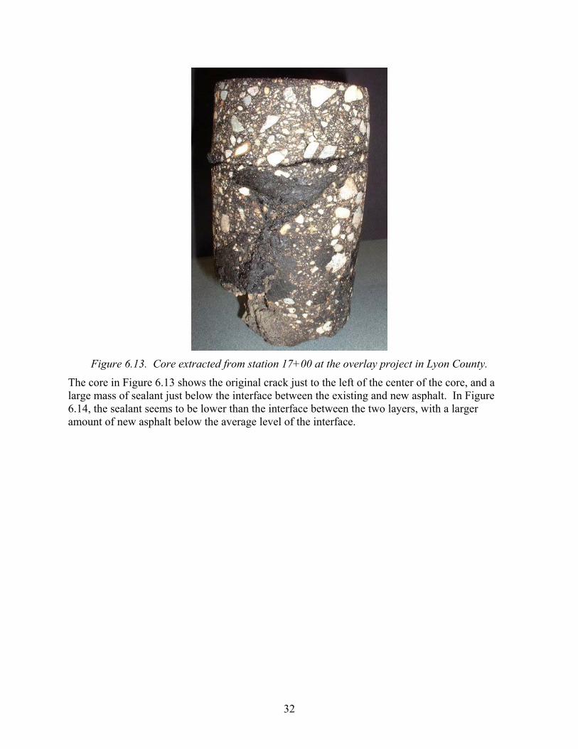
Figure 6.13. Core extracted from station 17+00 at the overlay project in Lyon County.
The core in Figure 6.13 shows the original crack just to the left of the center of the core, and a large mass of sealant just below the interface between the existing and new asphalt. In Figure 6.14, the sealant seems to be lower than the interface between the two layers, with a larger amount of new asphalt below the average level of the interface.

33
Figure 6.14. Core extracted from station 20+00 at the overlay project in Lyon County.
Crack Opening Analysis
The crack opening analysis was not originally part of this study. However, another theory was presented to the project team which suspected the cracks of closing due to the expansion of the existing asphalt pavement as the hot asphalt is placed on it, thus squeezing the joint sealant material upward. This analysis used demountable mechanical strain gauge (DEMEC) buttons to measure the opening and closing of the cracks during large temperature variations prior to the construction. The following data was recorded on the dates shown in Table 6.3. What is important to note in the table is not the absolute values in the Measurement column, but the change in measurement with temperature on July 16, 2004. The data on that date are reasonable, where the crack measurement decreases as the temperature increases. The reference measurement is constant, which is desirable. The average crack spacing of 25.6 feet, and the average change in measurement is 26.7 divisions over the 48-degree temperature change. Each division is 7.9x10⁻⁶ strains, and the closing of the crack is very small – only 0.042 mm. This is to be expected, however, since crack opening in asphalt pavement structures responds to changes in temperature throughout the entire structure, rather than change at the surface or in the top few inches. In asphalt pavement structures, movements are generally considered on a seasonal basis, rather than daily.

34
Date Time Location Measurement Surface Temp. 7/1/04 1:30 PM reference 813 108° F 22+31.2 842 22+57.5 594 22+82.5 815 7/16/04 7:50 AM reference 813 77° F 22+31.2 872 22+57.5 667 22+82.5 812 7/16/04 4:30 PM reference 813 125° F 22+31.2 852 22+57.5 630 22+82.5 789
Table 6.3. Crack opening data for CSAH 9, Lyon County.
Jackson County CR 84 In June 2004, project team members visited Jackson County and met with Jerry Palmer, maintenance supervisor in Jackson County, to visit the overlay construction site and to install thermocouples. This site involved more than simply recording pavement and sealant temperature as outlined in the work plan. It also included a comparison between two methods of crack treatment. The project location is at the county line between Jackson and Cottonwood County. The actual instrumentation site was placed on CR 43 in Cottonwood County. The Jackson County overlay was paved beginning approximately 200 feet inside Cottonwood County, where the cracks had been sealed previously that spring. Jackson County had not sealed the cracks on the same pavement on their side of the county line.
Background
The cracks in the project were routed and sealed in 2004 with Meadows 3405 Polymeric Compound sealant material, a 3725 Specification material. The rout was ¾ inch wide and ¾ inch deep, and the overbands were about 3 inches wide. Water was observed in the cracks beneath the sealant. This water would squirt out of the crack if stepped upon, and standing water was noted in the bottom of a crack in an area where the sealant was pulled away. The Cottonwood County maintenance supervisor indicated that the cracks were dry when the sealant was placed earlier in the spring. It is not known how the water got there, and why it had not drained. The overlay in Jackson County was placed 3 inches thick, in two 1½-inch lifts. The overlay was designed according to Mn/DOT 2360 specifications for a gyratory, level 2 design with B oil (PG 58-28).

35
Instrumentation
The HMA overlay extended into Cottonwood County approximately 200 feet. The overlay thickness varied. The first 100 feet received a 1½-inch overlay in one lift, and the second 100 feet received a 3-inch overlay in two lifts. This was done to observe the amount of reflective cracking of sealed cracks below. Only one sealed crack was instrumented with thermocouple wires and DEMEC buttons. The air temperature was approximately 75° F, with sunny skies and little wind. The thermocouples were installed at about 1:30 PM. The crack in the eastbound lane, located 54 feet west of address sign 49547, was chosen to be instrumented with thermocouple wires in accordance with the work plan.
Construction
At about 2:00 PM on Friday, August 20, 2004, the contractor indicated to the Jackson County staff that the westbound section of the project had been paved, but that they would not pave the eastbound section (the direction in which the instrumentation was located) until the following Monday. However, at about 6:00 PM that Friday, the contractor paved the eastbound section without contacting the county. In fact, the Jackson County engineers and maintenance staff were not notified of this until Monday morning, August 23. Because the time of paving was not known to the project team, the data logger was not retrieved before its memory was filled and the data was overwritten.
Observations and Comments
Dr. Wilde visited the site again on Tuesday, August 24, 2004, to obtain photographs and make observations before the second lift was placed. Bumps were observed, as expected, in the 200-foot section extending into Cottonwood County. The contractor had noticed the bumps as well, and ground them down to minimize the effect on smoothness. Some of the bumps observed that had been ground are shown in Figure 6.15. Very few, and very minor bumps were found in the Jackson County portion of the project. As noted, Jackson County had not sealed cracks on the project, while Cottonwood County had sealed them previously during the same season.

36
Figure 6.15. Bumps in 200-foot section in Cottonwood County.
Douglas County CR 23 and CR 9 In July 2004, Bill Zerfas visited Douglas County and met with Scott Green, assistant public works director, for the purpose of installing thermocouples in County Roads 23 and 9 for the project.
Background (CR 23)
County Road 23 (SAP 21-623-12) was last paved in 1985. The cracks were filled with AC-3 crack filler probably between 1989 and 1991. The segment of road where the instrumentation took place received a single-lift, 2-inch overlay. The overlay design is a Marshall LV mix with B oil (PG 58-28). No recycled material is allowed in the wear course, per Douglas County requirements. Before the 2-inch overlay, a tight blade-laid leveling course (TBL) using a grader was placed. The TBL is a fine-aggregate “sand mix” with 6.2 – 6.4% oil. The TBL mix was placed at about 35 pounds per square yard. The mix was then compacted with three passes of a pneumatic roller. The TBL was not calculated into the GE calculations for pavement design, it is only intended as a surface preparation prior to a HMA overlay.
Instrumentation (CR 23)
The monitored crack was in the northbound lane between Busch Road and Caribou Lane, near a trail stop sign located in the ditch. The air temperature was approximately 75° F, with sunny skies and little wind. The thermocouples were installed around 1:30 PM. There was very little AC-3 crack filler near the surface of the crack, and the AC-3 was not visible 2 inches below the crack. The thermocouple wires were installed in the crack at the ½-inch and 2-inch depths in accordance to the work plan.

37
Construction (CR 23)
On July 27, 2004, the tack coat and TBL were placed. The tack coat was applied at the instrumentation site at about 9:00 AM, and the TBL around 10:15 am. At this time, the roadway temperature was 86° F and the ambient air temperature was 69° F. The temperature of the TBL was 240° F out of the hopper, and decreased to 185° F after one pass with the pneumatic roller. The roller compacted the TBL in three passes. The site was paved on July 29, 2004. Data from the data logger was downloaded on July 30, but the data had become corrupted and no thermocouple information was obtained during the HMA paving. The site was revisited on August 3, 2004 at 9:45 am. No bumps were observed in the overlay. Douglas County has had good success with this method of TBL and report that bumps are not a problem with overlays that are preceded by a TBL.
Background (CR 9)
County Road 9 in Douglas County (SAP 21-609-08) was last paved in 1981. The overlay project was 6.6 miles (13.2 lane miles) long. The cracks were filled with AC-3 crack filler, probably about 1985 – 87. The segment of road where the instrumentation was placed received 3-inch overlay in two 1½-inch lifts. The overlay design was a Marshall LV mix with B oil (PG 58-28). Again, no RAP was allowed in the wear course, however, RAP was allowed in the non-wear course. Before the 3-inch overlay was placed, a tight blade-laid leveling course using a grader was placed, similar to the treatment at CR 23.
Instrumentation (CR 9)
The monitored crack was in the northbound lane just north of County Road 73. The air temperature was approximately 75° F, with sunny skies and little wind. The thermocouples were installed around 3:00 PM. The crack had quite a bit of AC-3 crack filler near the surface of the crack. Thermocouple wire #2 was installed in the AC-3 material. The other thermocouple wires were installed in the crack in accordance to the work plan. The thermocouple wires were checked and found to be recording temperatures, and these were re-checked the morning of July 27 and found to be working properly.
Construction (CR 9)
In a similar manner to the construction process on CR 23, CR 9 received a tack coat and TBL prior to the 2-lift, 3-inch overlay. No bumps were observed on the County Road 9 overlay after the first lift. Some of the data from the datalogger was lost during the transfer to the lab, so the only thermocouple data available for this segment is from the placement of the TBL. This is shown in Figure 6.16. Some of the AC-3 material was obtained and returned to the laboratory at the Office of Materials for testing.

38
Douglas County - CR 9
0
20
40
60
80
100
120
140
160
180
200
8/7/04 0:00 8/7/04 12:00 8/8/04 0:00 8/8/04 12:00 8/9/04 0:00 8/9/04 12:00
Time
Tem
pera
ture
, °F
Asphalt, 2 in.Asphalt, 0.5 in.Sealant, 2 in.Sealant, 0.5 in.Ambient
Figure 6.16. Temperature data from tight-blade leveling operation on County Road 9, Douglas
County.
Mn/DOT District 8 (US 212) The highway construction project observed on US 212 in District 8 was not originally planned as an instrumentation site. After being alerted to the occurrence of bumps in the overlay, the project team decided that it would be an opportunity to observe another project site and that it should not be missed.
Background
Cracks in the project had been sealed from the state line to TH 75 in 1998 with Crafco 231, a product meeting the Mn/DOT 3720 specification. This section was sealed using the rout and seal method. In 1999, the cracks were sealed from the intersection of TH 75 to Dawson, Minn., with Durafill 3405LM, a product also meeting the Mn/DOT 3720 specification. Again, the cracks were routed and sealed. At this time, the centerline (longitudinal) crack from TH 75 to the state line was sealed with the Durafill material. Bumps have occurred on both sides of TH 75, so manufacturer of sealant does not seem to be playing a role on US 212.
Construction and Observations
The unique conditions, and the willingness of the Mn/DOT District 8 engineers to work with the project team allowed for several methods to be tried for limiting or eliminating the occurrence of the bumps. Since the engineers notified the Office of Materials early in the project, different methods and applications were able to be designed and placed prior to the construction crew reaching those locations in order to prevent bump occurrence. This section describes the different methods that were tried on the US 212 overlay project. Figure 6.17 shows bumps in the

39
overlay which prompted the call to the Office of Materials, and Figure 6.18 shows the paver-laid thin-lift overlay placed prior to the 1½-inch lift on US 212.
• Along US 212, from MP 0 to MP 1+400, no sealant material was found in the cracks in this segment of road, so no additional measures were taken to prevent bumps.
• Between MP 2 and 3, the roadway received a paver-laid thin-lift overlay approximately ½-inch thick. The 1½-inch thick overlay was then placed over the thin-lift overlay. No bumps appeared in the thin-lift area, but further observations indicate that reflective cracking is occurring.
• Near the intersection of US 212 with TH 75 (approximately 12 to 13 miles from the state line), an area had been milled prior to the overlay placement (from the turning lane west of intersection to the bridge east of the intersection), a ½-inch paver-laid HMA layer was placed before the 1½-inch overlay. No bumps were observed in the milled area, and the majority of the reflective cracking appears to be in the shoulders.
Figure 6.17. Bumps in overlay on US 212 in District 8.

40
Figure 6.18. Paver-laid thin-lift overlay on US 212.
Summary One of the objectives of this project was to develop a short guidelines manual for asphalt paving personnel to use both during planning and design, as well as during the construction of an overlay. The information gained during the instrumentation site visits was invaluable in developing this set of guidelines, which can be found in Appendix B of this report. The construction practices, temperatures achieved in the existing asphalt concrete and crack sealant, and the personal discussions held with the paving personnel were all useful in identifying the common practices used in the field to avoid bumps in overlays and to mitigate their effects if they occur.

41
Chapter 7. LABORATORY TESTING This chapter discusses the laboratory testing program conducted on new and existing crack sealants for thermal expansion properties. Initially, the literature review and discussions with other engineers led the project team to form the opinion that the bumps occurring in overlays were most likely attributable to thermal expansion of crack sealant present in cracks in the existing asphalt concrete surface. However, after preliminary field observations and laboratory testing, it became apparent that the thermal expansion theory was unlikely as the primary cause of bumps in overlays. This chapter describes the laboratory testing conducted and the applicability of the results to the various bump occurrence theories.
Thermal Expansion Testing Thermal expansion testing was conducted on several samples, including new materials obtained from manufacturers and existing materials from the instrumented project sites. The team had developed a basic test for thermal expansion of sealants in the laboratory using an oven and graduated cylinder with temperature-measuring devices installed in the material. About the same time the samples were tested, the project team also collected the temperature data from the instrumentation sites. This temperature data was used in the development of the laboratory procedure. Since the highest temperature observed in the field when a new asphalt overlay is placed was less than 200° F, the samples were originally tested to just above that temperature. Eventually, as described in the next section, the samples were tested to temperatures up to the maximum recommended by the manufacturer.
Observations It became apparent that for the range of temperatures experienced by the sealant in the existing roadway, the sealants were not experiencing noticeable or measurable thermal expansion. In fact, the only noticeable expansion occurred after the sealant had been heated to over 300° F and approached the manufacturer’s recommended maximum temperature. At these temperatures, bubbles began to form in the sealant material, and it developed a fragile foam structure that expanded to more than double its original volume. However, this expanded foam structure of the sealant material readily collapsed upon being handled or disturbed in any way.
Conclusion The project team discussed the various theories regarding the cause of the bumps in overlays, and decided that thermal expansion was likely not a major contributor as had been previously thought. The project team decided that efforts could be better spent in additional field and laboratory testing of the sealant materials in order to investigate other, more promising theories. In accordance with this decision, the following additions were made to the instrumentation and laboratory testing plan.
• Add crack opening measurements to some instrumentation sites • Add rheological testing to new sealant material, including creep and recovery tests, strain
sweeps (complex shear modulus at different temperatures and strains), and master curves (based on complex shear modulus and loading times)
42
Laboratory Testing – Office of Materials This task originally included the testing of basic properties of the crack sealants obtained in the field at the instrumentation sites and their corresponding new materials. Over the course of the project, the team decided that additional testing would be warranted, in lieu of other testing, and proceeded with the following testing plan. The tests conducted include the following.
• Softening Point (ASTM D36, Ring and Ball Test) • Rheological Strain Sweeps • Rheological Master Curves • Creep and Recovery
These tests were conducted on samples meeting Mn/DOT 3719, 3723, and 3725 specifications, provided by various manufacturers. These included the following.
• Mn/DOT 3719 o CMC o Crafco o Meadows
• Mn/DOT 3723 o Crafco o Meadows o Maxwell (3723R and 3723V) o TH 101 (field sample) o McAsphalt
• Mn/DOT 3725 o McAsphalt o Crafco o 7503-31 (field sample) o JF 39 (field sample)
The following sections detail the results of the laboratory testing conducted at the Office of Materials at Maplewood, Minn. Much of the data obtained through this testing can be used for relative comparisons between the materials, but not specifically for correlating to the occurrence of bumps in the field during the placement of an overlay.
Softening Points
The softening point tests were conducted according to the ASTM D36 – Ring and Ball Softening Points standard test method. Although this test is becoming outdated, and is not used as often as it once was, the team felt that it may be a good method to determine the point at which the sealants become too soft to maintain an upward force on the first overlay lift. One objective was to determine if the softening points were higher or lower than the temperatures observed in the field.

43
The softening point data were determined on a variety of hot-pour joint sealants. Hot-pour joint sealant is a viscoelastic material that has no sharply defined melting point. The softening point is a temperature when the sealant will begin to flow. Relating to the behavior of the sealant in pavement, the sealant viscous properties take over at this temperature and the product become a liquid. As a liquid, the sealant material would provide little to no resistance in the creation of a bump in the overlay. The Mn/DOT Specification 3719 samples ranged in softening point from a low value of 181° F to a high of 221° F. Mn/DOT Specification 3719 joint sealant is an ASTM D6690 Type I containing recycled crumb rubber. Mn/DOT 3723 is a modified ASTM D 6690 Type II (3405) sealant, which calls for a more flexible material. The sealants tested which match this standard ranged from 190 to 212° F. Specification 3725 material is an ASTM D 6690 Type III (low modulus) modified material. Specification 3725 material has a lower resilience requirement. The samples tested in this category ranged in softening point from 169 to 188° F. Mn/DOT Specifications 3723 and 3725 require asphalt rubber products containing only virgin polymer. Using the thermal profiles generated in the field experiments, the sealant temperatures observed do not reach softening point temperatures of all the sealants tested. At these temperatures, the sealant still retains its elastic properties, resists deformation somewhat, and recovers for the loads placed on it. By definition the softening point is the temperature that a sealant starts to flow but is not entirely viscous.
Rheological Tests Rheology is the science of deformation and flow. Using the dynamic shear rheometer (DSR), temperature dependent properties, such as the complex shear modulus (G*), creep recovery, and phase angle (δ) can be determined. These properties give an indication as to how the sealant reacts in the pavement under field compaction temperatures. The complex shear modulus is a measure of total resistance of a material to deforming when repeatedly sheared. It consists of two parts, an elastic (recoverable) part and a viscous (non-recoverable) part. The phase angle, δ, is determined by measuring the amount of strain on a material when a known stress is applied. The time lag between the applied stress and resultant strain is δ, measured in degrees. A completely elastic material would give δ = 0° and a viscous material would have a phase angle approaching 90° F. Phase angle and complex shear modulus are highly dependent on temperature and the frequency of loading. At high temperatures, sealants behave like viscous fluids and will flow. At low temperatures sealants behave like elastic solids.
Strain Sweeps Strain sweep tests were conducted on the sealants to determine the linear viscoelastic range at the desired test temperatures. The complex shear modulus was measured at specified temperatures at increasing strain levels. This linear region is where G* is relatively independent of shear strain. It is important to maintain measurements within this linear region to obtain valid

44
fundamental material properties. Figure 7.1 shows the strain sweep results for a sample material. The decrease in complex shear modulus can be seen at both higher strains and at higher temperatures.
0 25.000 50.000 75.000 100.00 125.00 150.00 175.00% strain
0
250.0
500.0
750.0
1000
1250
1500
1750
2000
2250
|G*|
(Pa)
SS for JF58C using defaults-0001o
SS for JF58C using defaults-0001o, Using default valuesSS for JF58C using defaults-0001o, Strain sweep step 2SS for JF64C using defaults-0001o, Using default valuesSS for JF70C using defaults-0001o, Using default valuesSS for JF76C using defaults-0001o, Using default values at 76°C
76C
70C
64C
58C
Figure 7.1. Strain sweep results.
Rheological Master Curves Master curves are generated to identify time-temperature dependency of the sealants. Mathematical models calculate G*, phase angles and other properties for a wide range of loading times (frequencies) and temperatures from measurements made over smaller ranges. The complex shear modulus was measured at different temperatures and load frequencies. These plots then are shifted horizontally to form the master curve. Short loading times (higher frequencies) relate to lower temperature. The relative ranking of stiffness (G*) for the samples tested is shown in Table 7.1.
Stiff 3719 Lot Sample 3723 Field Sample 3723 Lot Sample 3725 Field sample
Less Stiff 3725 Lot sample
Table 7.1. Relative stiffness of selected sealant materials.
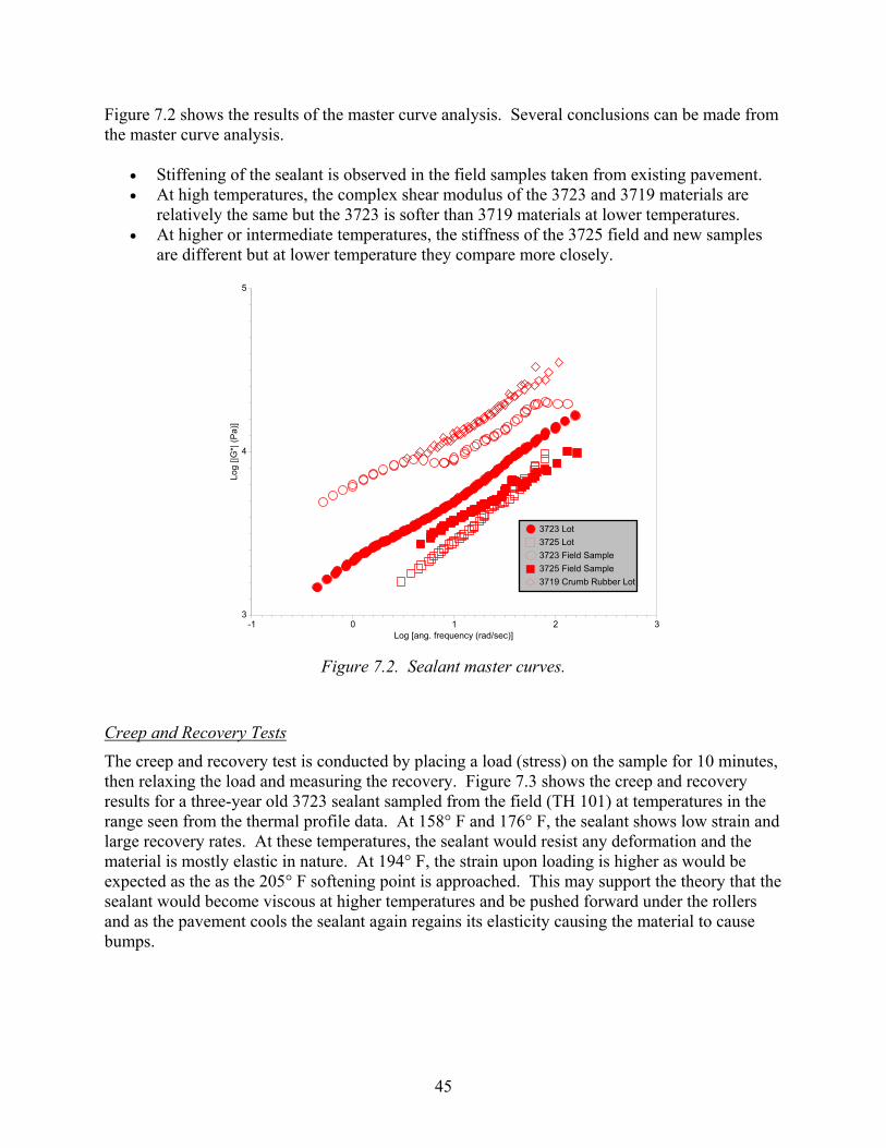
45
Figure 7.2 shows the results of the master curve analysis. Several conclusions can be made from the master curve analysis.
• Stiffening of the sealant is observed in the field samples taken from existing pavement. • At high temperatures, the complex shear modulus of the 3723 and 3719 materials are
relatively the same but the 3723 is softer than 3719 materials at lower temperatures. • At higher or intermediate temperatures, the stiffness of the 3725 field and new samples
are different but at lower temperature they compare more closely.
-1 0 1 2 3Log [ang. frequency (rad/sec)]
3
4
5
Log
[|G*|
(Pa)
]
3723 Lot3725 Lot 3723 Field Sample 3725 Field Sample3719 Crumb Rubber Lot
Figure 7.2. Sealant master curves.
Creep and Recovery Tests
The creep and recovery test is conducted by placing a load (stress) on the sample for 10 minutes, then relaxing the load and measuring the recovery. Figure 7.3 shows the creep and recovery results for a three-year old 3723 sealant sampled from the field (TH 101) at temperatures in the range seen from the thermal profile data. At 158° F and 176° F, the sealant shows low strain and large recovery rates. At these temperatures, the sealant would resist any deformation and the material is mostly elastic in nature. At 194° F, the strain upon loading is higher as would be expected as the as the 205° F softening point is approached. This may support the theory that the sealant would become viscous at higher temperatures and be pushed forward under the rollers and as the pavement cools the sealant again regains its elasticity causing the material to cause bumps.

46
0 100.0 200.0 300.0 400.0 500.0 600.0 700.0global time (s)
-0.25000
0
0.25000
0.50000
0.75000
1.0000
1.2500
1.5000
1.7500
% s
train
158 F
194 F
176 F
Figure 7.3. Field sample creep results of 3723 material.
Figure 7.4 shows a comparison of the creep and recovery results of 3725 and 3723 sealants. The softer 3725 sealant deforms more under loads but recovers more due to the increased polymer content and soft asphalt in the 3725 formulation. These results would indicate that 3725 might give more problems with creating bumps in an HMA overlay situation, but more field research needs to be done to confirm this.

47
0 100.0 200.0 300.0 400.0 500.0 600.0 700.0global time (s)
-0.025000
0
0.025000
0.050000
0.075000
0.10000
0.12500
0.15000
0.17500
0.20000
0.22500
% s
train
3725
3723
Figure 7.4. Creep comparison of 3723 and 3725 field samples.

48
Chapter 8. CONCLUSIONS AND RECOMMENDATIONS Initially, this project was intended to investigate the theory of thermal expansion of crack sealant as a major contributor to the occurrence of bumps in overlays. As discussed in the previous sections, however, observations made in the lab and in the field soon indicated that thermal expansion of the sealant material could not be causing bumps to form in new overlays. Consequently, the project team focused the testing and analysis efforts on some of the other theories that had been identified in the literature. Much of the field and laboratory testing was intended to disprove or support specific theories put forth by local engineers to explain the cause of bumps in overlays. These theories include:
1. Thermal expansion of crack sealant material 2. Moisture under existing layers turning to steam 3. Closure of cracks at high temperature – forcing sealant upward 4. Sliding of overlay material – creating a discontinuity and thus a bump 5. Sticking of overlay material – creating a discontinuity and thus a bump 6. Compression and subsequent expansion of sealant material
As stated, the thermal expansion theory was the initial focus of this project. The next two theories in the list were also addressed, and the project team found some evidence to suggest that none of the first three were contributing to the cause of bumps in overlays. The subsequent two theories – sliding and sticking of overlay material – seem to be contradictory, yet either could contribute to bump formation. The last theory in the list – compression and subsequent expansion of sealant material – seems to the members of the project team to be the most probable. Although the laboratory and field observations seem to corroborate this theory, and provide what could be called circumstantial evidence, there is no direct evidence to support it. The scope and resources of the project did not allow the team to investigate the final three theories in the list above in any detail. The remainder of this chapter discusses the results of the laboratory and field tests as they relate to the theories investigated, presents a short overview of the theories not evaluated, and then presents conclusions drawn from the results.
Evaluation of Theories The original theory investigated by the project team was the thermal expansion of crack sealant material. Later in the project, the team evaluated the moisture turning to steam and the crack closure theories as possible causes of bumps in overlays. Questions were raised about each of these as tests and field observations were conducted. The details of each are discussed in the following sections.
Thermal Expansion The tests conducted to evaluate the thermal expansion theory included field monitoring of crack sealant temperatures when the hot overlay mat was placed, laboratory tests of thermal expansion, and crack sealant softening point tests.
49
The combination of temperatures observed in the field and thermal expansion in the laboratory led the team to conclude that this theory could not contribute to the creation of bumps in overlays. In the sites instrumented, the maximum temperature attained by the crack sealant material in the original pavement was 190° F at the surface and about 135° F at 2 inches below the surface. Other temperatures were measured between 135 and 165° F at 0.5 inches below the surface. When comparing these temperature data to the thermal expansion results at these temperatures, it is unlikely that any significant thermal expansion takes place in the crack sealant when a hot overlay is placed on the existing surface.
Moisture to Steam No specific testing was conducted with respect to the moisture-to-steam theory, except to note the maximum temperatures below the surface of the existing pavement. As noted in the previous section, the temperatures observed did not exceed 165° F, which would not cause water to boil in the cracks. There may be some water vapor created, but a crack with a source of moisture is not a sealed vessel, and would most likely have an available release for the pressure, rather than causing a bump in the new overlay.
Closure of Cracks The third theory evaluated by the project team was the thermal expansion of the existing asphalt concrete pavement causing existing cracks to close. The narrowing of the cracks is said to cause the sealant to squeeze upward and form bumps in the overlay. Based on crack closure measurements conducted at CSAH 9 in Lyon County, the cracks closed about 0.042 mm over a temperature range of 48° F. This would indicate that over the range of temperatures recorded at the instrumentation sites, from a low temperature of 100 to 120° F to a high temperature of almost 200° F, and assuming the same rate of crack closure, the cracks may have closed a total of about 0.09 mm. For the crack-closure theory to be valid, the amount of closure and corresponding lateral compression would have to be several orders of magnitude larger. Thus, this theory is unlikely to be the cause of bumps in overlays.
Overview of Remaining Theories The theories which were not evaluated as part of this project include the sliding and sticking of overlay material, and the compression and rebound of sealant material.
Sliding of Overlay Material
This theory was expressed by several individuals who believe that, despite the tack coat which is placed between the existing asphalt pavement layer and the new overlay material, the crack sealant creates a slip surface at the interface between the two layers. According to this theory, the area that slips creates a discontinuity at a point just above the crack, where the crack sealant exists. This discontinuity, when compacted by the roller, causes the roller to slip slightly, and to push some of the hot asphalt mix into a bump. This theory was not evaluated as part of this project due to its late discovery and the limited resources in the project.
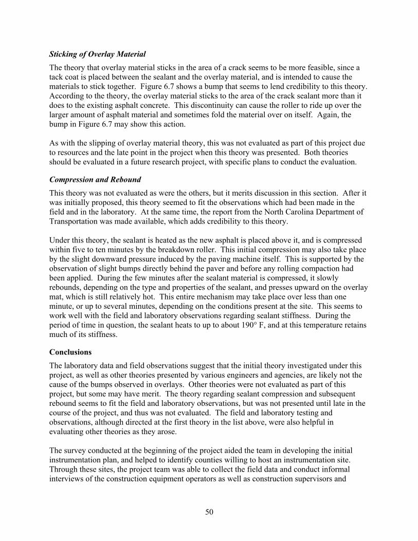
50
Sticking of Overlay Material The theory that overlay material sticks in the area of a crack seems to be more feasible, since a tack coat is placed between the sealant and the overlay material, and is intended to cause the materials to stick together. Figure 6.7 shows a bump that seems to lend credibility to this theory. According to the theory, the overlay material sticks to the area of the crack sealant more than it does to the existing asphalt concrete. This discontinuity can cause the roller to ride up over the larger amount of asphalt material and sometimes fold the material over on itself. Again, the bump in Figure 6.7 may show this action. As with the slipping of overlay material theory, this was not evaluated as part of this project due to resources and the late point in the project when this theory was presented. Both theories should be evaluated in a future research project, with specific plans to conduct the evaluation.
Compression and Rebound This theory was not evaluated as were the others, but it merits discussion in this section. After it was initially proposed, this theory seemed to fit the observations which had been made in the field and in the laboratory. At the same time, the report from the North Carolina Department of Transportation was made available, which adds credibility to this theory. Under this theory, the sealant is heated as the new asphalt is placed above it, and is compressed within five to ten minutes by the breakdown roller. This initial compression may also take place by the slight downward pressure induced by the paving machine itself. This is supported by the observation of slight bumps directly behind the paver and before any rolling compaction had been applied. During the few minutes after the sealant material is compressed, it slowly rebounds, depending on the type and properties of the sealant, and presses upward on the overlay mat, which is still relatively hot. This entire mechanism may take place over less than one minute, or up to several minutes, depending on the conditions present at the site. This seems to work well with the field and laboratory observations regarding sealant stiffness. During the period of time in question, the sealant heats to up to about 190° F, and at this temperature retains much of its stiffness.
Conclusions
The laboratory data and field observations suggest that the initial theory investigated under this project, as well as other theories presented by various engineers and agencies, are likely not the cause of the bumps observed in overlays. Other theories were not evaluated as part of this project, but some may have merit. The theory regarding sealant compression and subsequent rebound seems to fit the field and laboratory observations, but was not presented until late in the course of the project, and thus was not evaluated. The field and laboratory testing and observations, although directed at the first theory in the list above, were also helpful in evaluating other theories as they arose. The survey conducted at the beginning of the project aided the team in developing the initial instrumentation plan, and helped to identify counties willing to host an instrumentation site. Through these sites, the project team was able to collect the field data and conduct informal interviews of the construction equipment operators as well as construction supervisors and

51
engineers. These informal interviews, as well as the site interviews conducted during the summer of 2003, were instrumental in gaining the information used to develop the guidelines presented in Appendix B.
Recommendations The primary theory evaluated under this project, and the two others that were subsequently evaluated did not show a likelihood for causing bumps in overlays. The major benefits of this project, however, are the overlay projects database and the guidelines document which were created. The project team recommends that a more focused investigation into the compression and rebound theory be conducted. Another recommendation is that additional study be conducted to predict the probability of the occurrence of bumps in overlays. This project dealt with the prevention and mitigation of bumps, but further study should be undertaken to identify the combination of parameters that have a high probability of producing bumps. The project team also recommends that the LRRB publish the information in a pamphlet or by other means, to disseminate the information gained during this project. The information contained in Appendix B can be set in a format that will be easily usable by design and construction personnel representing the highway agency as well as the contractor. Using this information, designers can plan for contingencies in the case that bumps occur. They can also use past experience as an indicator, along with this information, to decide if mitigation procedures are necessary.

APPENDIX A. SURVEY OF CURRENT PRACTICE

A-1
May 15, 2003 County and State Pavement Engineers in Minnesota: The Local Road Research Board (LRRB) has approved funding for a project entitled Performance of Pavement Crack Sealants Beneath Bituminous Overlays. The study is being carried out by the joint team led by Dr. W. James Wilde of Minnesota State University, Mankato, and Mr. Bill Zerfas of Mn/DOT’s Office of Materials and Roads Research. The objective of this study is to determine why some bituminous overlays ‘bump’ when placed over sealed transverse cracks. The project team is seeking your input on bituminous overlays that have ‘bumped’ during the overlay process at sealed transverse cracks. The survey also asks for information regarding pre-treatments that you have tried on sealed transverse cracks prior to bituminous overlays and your success (or lack of) with these pre-treatment strategies. At this time, the study is limited to bituminous over bituminous (BOB) overlays. Please take a few minutes to share with us your overlay experiences as we attempt to better understand the reasons why some overlays ‘bump’, while others do not. We appreciate your input and time. If you would like a copy of the survey results, please indicate your physical or e-mail address at the top of the survey form. Thank you in advance for your help in this important project. Dr. W. James Wilde, P.E. Bill Zerfas, P.E. Assistant Professor Research Project Engineer Department of Mechanical and Civil Engineering Office of Materials and Road Research Minnesota State University, Mankato Minnesota Department of Transportation 205 E. Trafton Science Center 1400 Gervais Avenue Mankato, MN 56001 Maplewood, MN 55109

A-2
SURVEY
PERFORMANCE OF PAVEMENT CRACK SEALANTS BENEATH BITUMINOUS OVERLAYS
Name:
Agency:
Address:
City:
Phone number:
Would you like an electronic copy of the survey results sent to you? Yes
If Yes, what is your e-mail address:
Please either fill in this form using Microsoft Word and return it by email, or print it, fill out the form, and return it by mail or fax. Please answer all that apply.
1) Have any of your bituminous over bituminous (BOB) projects suffered from ‘bumps’ in the overlay at
sealed transverse cracks?
Yes No
i) If yes, please list project number(s) and the route location(s) where this occurred.
Project Number(s):
Route Location(s):
If you answered “YES” to question #1, please respond to questions 2 – 6.
If you answered “NO” to question #1, please go to question 7.
2) What was the thickness(es) of the bituminous overlay(s) that ‘bumped’ during construction?
Thickness:
3) What steps were taken to stop the ‘bumps’ that were being formed?
4) How were these steps effective / ineffective?
5) Do you have the project records available for the Project Team to review?
Yes No
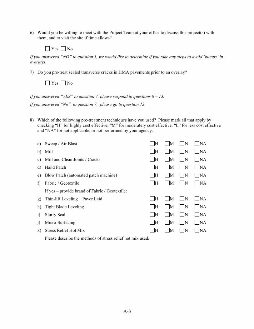
A-3
6) Would you be willing to meet with the Project Team at your office to discuss this project(s) with them, and to visit the site if time allows?
Yes No
If you answered “NO” to question 1, we would like to determine if you take any steps to avoid ‘bumps’ in overlays.
7) Do you pre-treat sealed transverse cracks in HMA pavements prior to an overlay? Yes No
If you answered “YES” to question 7, please respond to questions 8 – 13.
If you answered “No”, to question 7, please go to question 13.
8) Which of the following pre-treatment techniques have you used? Please mark all that apply by checking “H” for highly cost effective, “M” for moderately cost effective, “L” for less cost effective and “NA” for not applicable, or not performed by your agency.
a) Sweep / Air Blast H M N NA
b) Mill H M N NA
c) Mill and Clean Joints / Cracks H M N NA
d) Hand Patch H M N NA
e) Blow Patch (automated patch machine) H M N NA
f) Fabric / Geotextile H M N NA
If yes – provide brand of Fabric / Geotextile:
g) Thin-lift Leveling – Paver Laid H M N NA
h) Tight Blade Leveling H M N NA
i) Slurry Seal H M N NA
j) Micro-Surfacing H M N NA
k) Stress Relief Hot Mix H M N NA
Please describe the methods of stress relief hot mix used.

A-4
9) Do the following factors play a role in the type of pre-treatment strategy used? a) Type (structure) of Road. Yes No
If ‘Yes’, Explain:
b) Age of Road. Yes No
If ‘Yes’, Explain:
c) Volume of Traffic: Yes No
If ‘Yes’, Explain:
d) Age of Crack Sealant: Yes No
If ‘Yes’, Explain:
e) Type of Crack Sealant: Yes No
If ‘Yes’, Explain:
10) What are the most cost effective pre-treatment techniques?
11) What are the most successful pre-treatment techniques?
12) What are the least successful pre-treatment techniques?
If you answered “NO” to question 7, please answer the following questions as they relate to the 2003 construction season.
13) Do you have any BOB projects scheduled for the 2003 Construction season?
Yes No
If yes, what are the projects numbers and dates of construction?
14) Would you consider any of them a potential candidate for ‘bumps’ based on your experience?
Yes No
If yes, would you be willing to meet with the Project Team to discuss the possibility of instrumenting a small portion of the site for research purposes?
Yes No

A-5
Your Survey is Finished! Thank you for your time, this information is very helpful. Please return your survey by fax or email to: Dr. W. James Wilde, P.E. Minnesota State University, Mankato Phone: (507) 389-5252
Fax: (507) 389-5002 e-mail: [email protected]

APPENDIX B. BUMP AVOIDANCE BOOKLET

Common Practices for Avoiding Bumps in Overlays(and what to do if they occur)
Minnesota Local Road Research Board
July 2005
July 2005LRRB Publication No. %%%
Fron
t Cov
er
Bac
k C
over

This informational booklet is intended to aid local and state highway construction, maintenance, and design staff understand the potential causes and possible remedies for bumps that occur during overlay construction.
This booklet comprises the actual experiences and field observations of those familiar with overlay paving in Minnesota – county engineers, contractors, and paver and roller operators. The strategies contained herein have provided good results for those who have used them.
The Local Road Research Board does not specifically endorse any particular method described in this booklet, but encourages local agencies to experiment with those that seem promising and to implement those strategies that work best for them.
Further information can be obtained by contacting the Minnesota Local Road Research Board at www.lrrb.org.
Common Practices for Avoiding Bumps in Overlays(and what to do if they occur)
1Avoiding Bumps in Overlays – Common PracticesAvoiding Bumps in Overlays – Common Practices

Avoid sealant overbandingMany agencies recommend applying the smallest overband possible with the equipment available. This usually means using a two-inch wide wand or simply filling a routed crack with no overband at all.
Crack Sealing
2 Avoiding Bumps in Overlays – Common Practices
Let the sealant material ageA common practice is to avoid overlay placement until the sealant has aged for at least one year in the field. There may be some benefit to a stiffer sealant material when placing an overlay.
Crack Sealing
3Avoiding Bumps in Overlays – Common Practices

Leave sealant material below pavement surfaceAnother sealant material option is to rout and seal, and fill the rout so that the surface of the material is about ¼ inch below the surface of the existing pavement. When the overlay material is pressed into the rout and onto the sealant material, there will be some space available for the material to go without forming a crack.
Crack Sealing
Remove sealant materialOne way of removing the sealant material is by ripping it out with a small backhoe and hook attachment. In most cases, the sealant “ropes” can be pulled from the cracks and removed from the pavement.
Once the sealant material is removed, there is little probability of bumps occurring.
This method is labor-intensive, especially if the sealant does not come out of the cracks in long ropes. There is usually some residual sealant material that must be either removed before overlay placement or left in the cracks.
Remove the Sealant Material
5Avoiding Bumps in Overlays – Common Practices4 Avoiding Bumps in Overlays – Common Practices

Mill before overlayingAnother way of removing the sealant from the roadway is to mill the project prior to overlaying. Care must be taken, however, with the milling equipment and the type of sealant material. Some types of material may be detrimental to the operation of the equipment.
If the milled asphalt is intended to be used as recycled material, it must not contain used crack sealant. In this case, the sealant must be removed prior to milling, as described in the previous section.
Remove the Sealant Material
Mill and fill a narrow pathAnother suggestion for removing the sealant material is to mill a 1-inch deep, 12-inch wide path transverse to the roadway centerline. This will remove the sealant and much of the raveled crack edges, if any.
Immediately fill the milled section with hot mix to restore the roadway surface until the overlay is placed.
Care should be taken when employing this method, however, because sealant material can become hot and render the milling apparatus inoperative.
Remove the Sealant Material
7Avoiding Bumps in Overlays – Common Practices6 Avoiding Bumps in Overlays – Common Practices
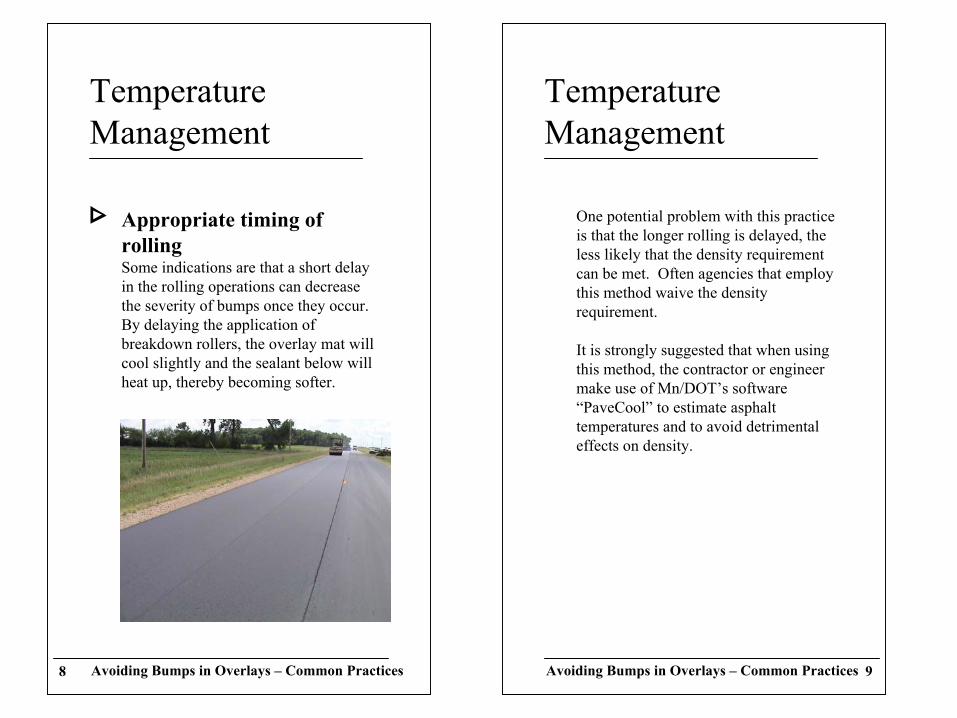
Appropriate timing of rollingSome indications are that a short delay in the rolling operations can decrease the severity of bumps once they occur. By delaying the application of breakdown rollers, the overlay mat will cool slightly and the sealant below will heat up, thereby becoming softer.
Temperature Management
9Avoiding Bumps in Overlays – Common Practices8 Avoiding Bumps in Overlays – Common Practices
One potential problem with this practice is that the longer rolling is delayed, the less likely that the density requirement can be met. Often agencies that employ this method waive the density requirement.
It is strongly suggested that when using this method, the contractor or engineer make use of Mn/DOT’s software “PaveCool” to estimate asphalt temperatures and to avoid detrimental effects on density.
Temperature Management

Overlap roller typesIf bumps are observed, a method that works for some roller operators is to overlap vibratory and pneumatic rollers. By alternating passes between steel-drum vibratory and rubber-tire pneumatic rollers, the kneading process seems to work the bumps back down in some cases.
Roller Operations
11Avoiding Bumps in Overlays – Common Practices10 Avoiding Bumps in Overlays – Common Practices
Use a small roller transverselyIf bumps are observed, one practice to mitigate their severity is to use a small “walk-behind” roller to apply additional compaction to the specific area needed. Applying additional compaction with full-size vibratory rollers generally results in worsening the bumps and pushing the overlay material back and forth above the crack.
Additional Compaction

Hold back finish rollerAnother method used in some cases to recompact bumps that have formed is to hold the finish roller until the mat has cooled to approximately 120° F. At this temperature, the finish roller may be able to compact the overlay material further in the area of the bump, and keep it down.
Roller Operations
13Avoiding Bumps in Overlays – Common PracticesAvoiding Bumps in Overlays – Common Practices12
Use single vibratory drumAfter noticing the formation of bumps, some roller operators have reported fewer bumps by using the lead drum as the drive roller and setting it to static operation. The following drum is then left as to provide the vibratory compaction.
While this may not remove bumps that have already formed, it is reported that this practice can sometimes reduce the probability of further bumps forming.
Roller Operations

Tight-blade levelingPlace a thin-lift, grader-placed, fine-aggregate layer on the surface of the existing pavement prior to overlay placement. Some agencies suggest that the motor grader scrape the surface of the pavement when conducting this operation to place a very thin layer. Other agencies suggest placing a slightly thicker layer. All those who suggest this method recommend compaction of the thin layer with rubber-tire rollers.
Traffic may be allowed on the roadway between the application of the tight-blade leveling course and the overlay.
Pre-Overlay Preparation
15Avoiding Bumps in Overlays – Common PracticesAvoiding Bumps in Overlays – Common Practices14
Don’t over roll A common rule of thumb from roller operators is not to over roll the mat when bumps have occurred. As mentioned previously, addition rolling to compact the bumps often results in worsening the situation by pushing the overlay material back and forth above the crack.
Roller Operations
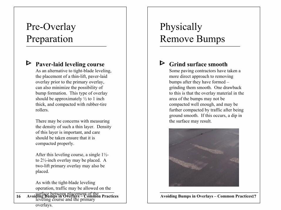
Grind surface smoothSome paving contractors have taken a more direct approach to removing bumps after they have formed –grinding them smooth. One drawback to this is that the overlay material in the area of the bumps may not be compacted well enough, and may be further compacted by traffic after being ground smooth. If this occurs, a dip in the surface may result.
PhysicallyRemove Bumps
17Avoiding Bumps in Overlays – Common PracticesAvoiding Bumps in Overlays – Common Practices16
Paver-laid leveling courseAs an alternative to tight-blade leveling, the placement of a thin-lift, paver-laid overlay prior to the primary overlay, can also minimize the possibility of bump formation. This type of overlay should be approximately ½ to 1 inch thick, and compacted with rubber-tire rollers.
There may be concerns with measuring the density of such a thin layer. Density of this layer is important, and care should be taken ensure that it is compacted properly.
After this leveling course, a single 1½-to 2½-inch overlay may be placed. A two-lift primary overlay may also be placed.
As with the tight-blade leveling operation, traffic may be allowed on the surface between placement of the leveling course and the primary overlays.
Pre-Overlay Preparation

19Avoiding Bumps in Overlays – Common PracticesAvoiding Bumps in Overlays – Common Practices18
The second lift is usually betterWhen constructing a two-lift overlay, the first lift bears the effects of the crack sealant, and the second lift is almost always bump free. Some of the previous suggestions are almost equivalent to the two-lift recommendation. Many overlays thicker than two inches are designed to be constructed in two-lifts.
Construct Two-Lift Overlay