final report on caes sitting in northeastern colorado · final report on caes sitting in...
TRANSCRIPT

Final Report on CAES Sitting in Northeastern Colorado
University of Colorado‐Boulder Energy Storage Research Group: http://www.colorado.edu/engineering/energystorage/
Department of Geological Sciences
Todd Jesse‐ [email protected] Dr. David Budd‐ [email protected]
Department of Electrical Engineering
Dr. Frank Barnes‐ [email protected] Jonah Levine‐ [email protected]

2
Table of Contents Executive Summary ................................................................................................................................................. 3 Introduction ................................................................................................................................................................ 4 Methods ........................................................................................................................................................................ 5 Results ........................................................................................................................................................................... 6 Bedded Salts ........................................................................................................................................................... 6 Saline Aquifers ................................................................................................................................................... 13 Abandoned Oil and Gas Fields..................................................................................................................... 26
Bibliography ............................................................................................................................................................ 29

3
Executive Summary Bedded salts, saline aquifers and abandoned oil and gas fields in northeastern
Colorado were evaluated to determine if there were any suitable geologic conditions for
compressed air energy storage (CAES) in that area. Evaluation criteria were taken from
Succar (2008) and focused on depth of burial, unit thickness, porosity & permeability, and
presence of an overlying seal. Key findings are:
1. Bedded salts, with anywhere from ~140 to ~400 ft of net soluble salt occur in
Washington and Morgan counties at depths of 4500 to 6000 feet. Individual salt
beds can be >100 ft thick. Anhydrite forms a suitable cap seal. These salts are one
possible candidate for a CAES repository
2. Uppermost Dakato Group sands (D‐sands) at depths > 3,0000 ft occur across ~
5,750 sq miles in the far eastern portion of the state and have sufficient thickness
(~40 ft) , porosity (probably >25%), and permeability (probably > 250 md) to form
a CAES site. Trapping would probably be by lateral variations in rock types (i.e., a
stratigraphic trap), not by structural deformation.
3. The only shallow and abandoned oil and gas field in a geologic unit (the Dakota D‐
sand) with sufficient porosity and permeability is Chappel Field, which occurs at a
depth of 3000 ft in the northeastern corner of Sedgwick County. The field though is
small (~0.2 km2), thus unless the trap is vastly under filled with hydrocarbons, it
would probably be too small for CAES.
4. Bedded evaporate deposits (Blaine Formation) near the Las Animas arch (Lamar)
and the Niobrara chalk (saline aquifer and abandoned oil & gas fields throughout NE

4
Colorado) occur at appropriate depths for CAES, but are not suitable due to either
their composition and thinness (Blaine Fm.), or lack of permeability (Niobrara).
Introduction This study was conducted to determine the suitability of geologic formations for
CAES in northeastern Colorado. The main objective of this study was to take the first step
in identifying potential geologic repositories in northeastern Colorado such as: bedded
salts, saline aquifers and abandoned oil and gas fields. Criteria for assessing geologic units
for compressed air energy storage (CAES) were taken from Succar’s (2008) discussion of
baseload power production from wind turbine arrays coupled to compressed air energy
storage (Table 1). Key parameters considered herein were depth (<3,000 ft), thickness,
porosity, permeability, and presence of an overlying seal.

5
Table 1.‐Ranking Criteria for Candidate Sites for Aquifer CAES used to evaluate saline aquifers in northeastern Colorado (Succar, 2008, Page 51)
Methods Cross sections of the northeastern portion of the state, created by the Rocky
Mountain Association of Geologist (RMAG), were examined to determine if there were any
bedded salts in the subsurface of northeastern Colorado, and to determine what potentially
porous (i.e., non‐shale) geologic units were also present at depths < 3,000 ft in the same
area. The later have the potential to be regional saline‐water aquifers and locally shallow,
abandoned oil or gas fields. Very shallow surficial potable groundwater aquifers at tens to
a few hundreds of feet were not pursued on the assumption that these geologically very
young, structurally undeformed and sand‐rich units would not contain appropriate
geological scenarios to allow the localized trapping and containment of any compressed air.

6
Once salt‐bearing and potentially porous rock units were identified, the Colorado Oil
and Gas Conservation Committee’s (COGCC) online database was exploited to collect data
on each unit’s depth, gross thickness, and in the case of salts, the net salt thicknesses and
lateral extent of the salt formations. The COGCC’s online database contains borehole data
gathered from all oil and gas drill holes across the state of Colorado. The data collected
allowed mapping of each unit’s areal extent, subsurface depth, and structural surface
(elevation relative to sea level) using the computer mapping programs PETRA and PATREL.
The regional structural maps indicate the potential for storage of compressed air in
structural traps (i.e., containment of the injected air where the porous units had been
deformed).
Select well logs from the COGC data base were also used to assess lithologic
heterogeneity of each unit. This was possible because salt, limestone, sandstone, and shale
can be readily distinguished from each other by a variety of borehole geophysical tools.
Permeability and porosity of the candidate saline aquifer units were assessed using data
gathered from the published geological literature on the oil and gas fields of the region.
Results
Bedded Salts Geologists refer to all minerals evaporated from seawater as “salts” or “evaporites”.
Of these, the dominant forms are the minerals anhydrite (CaSO4), gypsum (CaSO4*2H2O),
and halite (NaCl). The later is far more soluble than the former two and is the sole mineral
generally referred to when discussing “salt” in the singular. Halite is also the only one of
the three common evaporate “salts” that can be dissolution mined to form a CAES cavern.

7
The others, in fact typically form the top seal for such many types of salt storage caverns
(e.g. Chevron’s Windy Hill gas storage facility near Brush).
Shallow (<3,000 ft) Eastern Colorado Evaporite Beds The only evaporite
formation found in Eastern Colorado at subsurface depths less than 3,000 feet is the Blaine
Gypsum Formation, which is up to 18m thick but regionally averages less thickness. The
unit consists of the mineral anhydrite or gypsum. The unit is shallowest in southeastern
Colorado (i.e. the Lamar area) where it occurs at depths of < 2,500 ft. In northeastern
Colorado (Sterling, Brush, Wray, etc) it is generally below 5,000 ft.
Figure 1.‐ Induction log from ~1300 to 1400 feet, subsurface depth, showing the different rock types composing the Blaine Gypsum Formation in southeastern Colorado.
8
Because of its anhydrite/gypsum composition, the Blaine evaporites cannot be
recommended as a suitable CAES unit. Also, given that there needs to be a void storage
volume of 200,000 m3 in order to generate 1 GWh of CAES capacity, the area covered by a
Blaine storage system would be large. An 18m thick unit of Blaine that is 75% evaporite
minerals would have to be around 14.8 km2which would seemingly be an unreasonably
large area for even a consortium of storage sites.
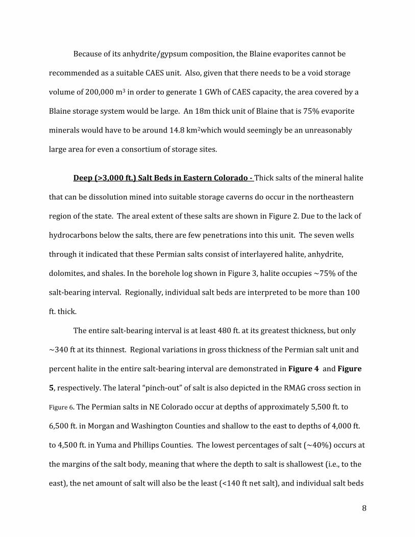
Deep (>3,000 ft.) Salt Beds in Eastern Colorado Thick salts of the mineral halite
that can be dissolution mined into suitable storage caverns do occur in the northeastern
region of the state. The areal extent of these salts are shown in Figure 2. Due to the lack of
hydrocarbons below the salts, there are few penetrations into this unit. The seven wells
through it indicated that these Permian salts consist of interlayered halite, anhydrite,
dolomites, and shales. In the borehole log shown in Figure 3, halite occupies ~75% of the
salt‐bearing interval. Regionally, individual salt beds are interpreted to be more than 100
ft. thick.
The entire salt‐bearing interval is at least 480 ft. at its greatest thickness, but only
~340 ft at its thinnest. Regional variations in gross thickness of the Permian salt unit and
percent halite in the entire salt‐bearing interval are demonstrated in Figure 4 and Figure
5, respectively. The lateral “pinch‐out” of salt is also depicted in the RMAG cross section in
Figure 6. The Permian salts in NE Colorado occur at depths of approximately 5,500 ft. to
6,500 ft. in Morgan and Washington Counties and shallow to the east to depths of 4,000 ft.
to 4,500 ft. in Yuma and Phillips Counties. The lowest percentages of salt (~40%) occurs at
the margins of the salt body, meaning that where the depth to salt is shallowest (i.e., to the
east), the net amount of salt will also be the least (<140 ft net salt), and individual salt beds

9
are no more than 70 ft thick. A CAES repository would still seem feasible, but its height and
area would differ from a site in the purer and thicker salt intervals.
Figure 2‐ Approximate location of Permian salt beds in Northeastern Colorado. This preliminary map is based solely on two geological cross sections through the area published by RMAG in 1976.The lack of hydrocarbons below the salt interval means that there are few penetrations into the salt; only seven were found in the COGC database, consisting of 4 on the 1976 RMAG cross sections that constrain this map, one well at the Windy Hill Gas Storage facility, and two other wells.
10
Figure 3– Neutron density log from ~5600 to 6150 feet, subsurface depth, showing the different rock types composing the Permain Salt interval in northeastern Colorado. Note that the salt is not a homogeneous unit, but a heterogeneous interlayering of halite beds with anhydrite, dolomite, and shales.

11
Well # API # County Township & Range
Depth to Top
Gross Thickness
% Halite
1 087‐05899 Morgan 32 3N 55W 5923 ft. 410 ft. 84 % 2 121‐09845 Washington 33 5N 54W 5650 ft. 363 ft. 73 % 3 121‐10006 Washington 28 4N 53W 5748 ft. 483 ft. 43 % 4 125‐05156 Yuma 21 4N 48W 4573 ft. 337 ft. 41 % Table 2,‐ Location, gross thickness and % halite of salt‐bearing interval used to construct Figure 4 and Figure 5. Figure 3 shows the salt section of Well #2 and is from the Windy Hills gas repository. Three additional wells the penetrate the salt unit are recorded in the COGC database, but do not contain well logs, and thus gross thickness and % halite in those wells could not be determined.
Figure 4.‐Gross thickness of the salt‐bearing interval shown at different well locations across northeastern Colorado. Wells are the same as Table 2.
Figure 5.‐ Percent halite of the salt‐bearing interval shown at different well locations across northeastern Colorado. Wells are the same as Table 2.

12
Figure 6. ‐ Cross‐section of upper Permian units in eastern Colorado (section D‐D’, RMAG, 1976). Salt (square pattern for rock type) is present in the two wells in the center of the cross section, but absent in the two wells on the margins of the section, indicating the salt depositional basin terminated laterally.
The Chevron Corporation plans to utilize these thick Permian salts in the Windy Hill
Gas Storage facility near Brush, Colorado.(Unocal Windy Hill Gas Storage) The Windy Hill
repository is at a depth of ~6,000 ft in a 370‐foot interval consisting of inter bedded salt,
anhydrite, and shale. The cap rock (upper seal) of the storage interval is ~60 feet of the
Chugwater Anhydrite. The underlying caverns will be made in the Permian Salt Unit, which
SUPERIOR WEISS #45‐32 32‐3N‐55W
Morgan Co., Colorado
AMERADAC.J. HEYEM #1 7‐2S‐52W
Washington Co., Colorado
CALCO MUMM #1 1‐3S‐48W
Yuma Co., Colorado
HERNDON DRLG. HEGARTY #1 14‐1N‐59W
Morgan Co., Colorado
Halite Anhydrite

13
consists of 143 ft. of the upper salt, 50 feet of theOpeche Shale, and 178 feet of the lower
salt. Each cavern will be solution‐mined from a single wellbore. Insoluble material is
expected to take up approximately 25 percent of the cavern space, and the open space
dimensions of the caverns will be approximately 226 by 260 feet. The distance between
each cavern ranges from 1,041 feet to 1,320 feet.
Saline Aquifers Two potential saline aquifers that occur at depths > 3,000 ft in northeastern
Colorado were identified as potential CAES candidates ‐‐‐ the Niobrara chalk and the
sandstones of the Dakota Group. Shales dominated the rest of the shallow stratigraphic
section. COGC database yield data on approximately 120 well sites for the Niobrara and
100 well sites for the upper most Dakota sandstone (known as the “D‐sand”).
Niobrara Chalk The Niobrara Chalk, also known as the Smokey Hills Member of
the Niobrara Formation, is a Cretaceous deposit whose burial depth shallows from the
center of the Denver‐Julesberg Basin eastward into Kansas and south onto the Las Animas
Arch (Figure 7). It is an interlayered chalk and shale that can be found at subsurface depths
of 3,000 ft. and greater in Washington and Logan counties to depths as shallow as ~1,500
ft. in southeast Yuma county near the Kansas boarder. Topography on the top of the unit
reflects some type of structural deformation.
The Niobrara chalk is capped by roughly 2,000 ft. of the Pierre Shale, which would
form an excellent top seal to any CAES repository. The entire Niobrara unit is up to ~400 ft
thick with porosities typically of 25%‐30% in the chalk (Figure 8; Byrnes et al., 2005). The

14
uppermost 30‐40 ft can be even more porous and is the gas‐bearing interval in Niobrara
chalk gas fields of northeastern Colorado, western Kansas, and southwestern Nebraska.
Thickness of that uppermost gas reservoir interval varies by field. Data from six Niobrara
gas field (Table 3) reveal that although the unit is very porous it is not very permeable.
Porosity is the volumetric space in the geologic formations where as permeability the
connectivity of those spaces. Both volumetric space as well as connection of those spaces is
needed to flow in, store, and flow out the high pressure air. The very small size of the
calcite crystals in a chalk makes for very small pore spaces (David A. Budd, personal
communication). As a result, the permeability of the Niobrara chalk is typically less than 1
md (Table 3) and never greater than 3‐5 md (Byrnes et al., 2005; Watney, 2005).
Field Name Depth Porosity Permeability
DE NOVA 3000 ft. 32 % .1md
ROCK CREEK 2800 ft. 33% 0.1‐0.5 md
WAGES 2800 ft. 33% 0.1‐0.5 md
WAVERLY 2800 ft. 33% 0.1‐0.5 md
OLD BALDY 2700 ft. 33% 0.1‐0.5 md
ECKLEY 2700 ft. 33% 0.1‐0.5 md
Table 3‐ Porosity and permeability values taken from Colorado and Nebraska oil and gas field volumes by the Rocky Mountain Association of Geologists. These values are similar to those reported by Byrnes et al. (2005) and Watney (2005).
In spite of low permeabilities the chalk is a productive natural gas unit because it is
very brittle, which leads to natural fracturing that increases the overall permeability of the
40‐ft reservoir interval. That is, storage is in the chalk’s high porosity, but delivery to the
well bore is through the fracture, not the matrix permeability. These fractures do not
extend into the more ductile Pierre Shale, thus maintaining the structural integrity of the
overlying Pierre Shale.

15
A 3D structural map of the formation shows that there are structural traps where
there may be enough closure to hold compressed air (Error! Reference source not
found.). But, while there still may be closure, the permeability of the formation renders it
unusable for CAES according to the criteria for candidate sites established by Succar
(2008).

16
Figure 7‐ Contour map of the depth to the top of the Niobrara from surface elevation. The map displays the uppermost northeast corner of the state and is bordered by Kansas to the east, Nebraska to the northeast and Wyoming to the north. The bottom of the map is the Yuma county border and the western edge of the map is an arbitrary boundary in Washington and Logan counties chosen past the 3000 ft. contour line. County names and boundaries are drawn in violet. This map was made with approximately 120 data points from the Colorado Oil and Gas Conservation Committee’s online data‐base (http://oil‐gas.state.co.us/).

17
Figure 8. – Neutron porosity log from a gas well in the Old Baldy Field, Yuma county, northeastern Colorado. Top of the Niobrara chalk is at 2550 ft (subsurface elevation). Porosity is high throughout the entire unit, and particularly high in the gas bearing uppermost 40 ft. The bentonite‐rich shales of the overlying Pierre Shale form the capping seal.

18
Figure 9. – Three‐dimensional structural map of the Niobrara Formation in the northeastern corner of Colorado. View is looking southeast from the Wyoming boarder. Map shows that the Niobrara shallows to the east into Nebraska and Kansas and to the south onto the Las Animas Arch. The purple dots are well locations where data was gathered. Elevation is measured from sea level. Data is from the same map as in Figure 7.

19
Uppermost Dakota Group Dsands The lower Cretaceous Dakota Group consists of
alternating shale and sandstone (Figure 10), with the uppermost sandstone known as the “D-
sand”. The D-sand houses oil and gas fields throughout northeastern Colorado, but where oil or
gas is not trapped, the D-sand (and all other Dakota Group sands) is a saline water aquifer.
Figure 10. -Simplified stratigraphic column that displays the different subsurface units recognized within the Dakota Group, as well as the formations encasing the Dakota. The stratigraphic column was constructed using well logs found on the COGCC online database.
The D‐sand burial depth shallows from the center of the Denver‐Julesberg Basin
eastward into Kansas and south onto the Las Animas Arch (Figure 11). The D‐sand can be
found at subsurface depths of more than 6,000 ft. in Logan County but as shallow as 2,000
ft in Kit Carson County in the east‐central portion of the state as it begins to rise onto the
Las Animas Arch. The top of the D‐sand is at >3000 ft over ~5,750 sq miles in Kit Carson
and southern Yuma counties.
Topography on the top of the unit also shows structural deformation (Figure 12).
Deformation has the potential to provide closure that will trap compressed air, however,
most of that deformation on the D‐sand occurs at depths greater than 1600 ft and in the
northeastern portion of the map area.In the absence of structural trapping, sands of the

20
Dakota are known to still have closure due to stratigraphic trapping (Table 4). Stratigraphic
traps are ones in which lateral variations in rock type (which formed when the sediments
were originally deposited on the land surface in Cretaceous time) provide the closure.

21
Figure 11.- Contour map of the depth to the top of the D-sand from surface elevation. The map displays the upper most northeast corner of the state with Wyoming to the north, Kansas to the east and Nebraska to the northeast. The bottom of the map is near the southern border of Kit Carson County and the western edge is an arbitrary boundary in Washington, Logan and Kit Carson counties chosen to demonstrate the depths the formation is found at in this portion of the state. This map was constructed using approximately 100 data points from the Colorado Oil and Gas Conservation Committee’s online data-base (http://oil-gas.state.co.us/). As shown above the formation shallows to the east into Kansas and to the south onto the Las Animas Arch.
Figure 12.‐Three dimensional structural map of the d‐sand in the northeast corner of Colorado. The view is looking southeast from the Wyoming border. Map shows that the D‐sand shallows as it goes east into Kansas and south onto the Las Animas Arch. Elevation is measured from sea level. The yellow dots are well locations where data was collected. Data is from the same map as in Figure 11.

22
Field Name Depth (ft.) Porosity (%) Permeability
(md) Type of Trap
AKRON EAST ATWOOD EAST BASE LINE BEACON BUGLE BUSY BEE CHAPPEL COMANCHE CREEK DARBY CREEK DIVIDE ELM GROVE FENCE POST FRASCO HORSE CREEK IRONDALE JACKPOT JAMBOREE KRAUTHEAD LANYARD LITTLE HOOT LITTLE HOOT SO NUGGET RED LION RUNNING CREEK SAND RIVER YOUNG
4500 4400 7500 5800 8200 6400 3000 7500 4900 4700 4500 7600 5500 7500 7900 6400 7900 7700 6800 5100 5100 5300 3800 8300 5100 5800
2223
8.5 19.3 10 15
24 14 16 23 20 8.5 17 8.6 9 15.8 5 9.6 15.2 15 15 19 29
12 20 20.2
37580
0.79 175 100 135
N/A 20
N/A 250
N/AN/A
199 N/A
15 60 0.1 10.7 48.7 20 16 157
N/AN/A
150 500
Structural/StratigraphicStructural/StratigraphicStratigraphic Stratigraphic Stratigraphic Stratigraphic Stratigraphic Stratigraphic Stratigraphic Stratigraphic Stratigraphic Stratigraphic Stratigraphic Stratigraphic Stratigraphic Stratigraphic Stratigraphic Stratigraphic Stratigraphic Stratigraphic Stratigraphic Stratigraphic Stratigraphic Stratigraphic Stratigraphic Stratigraphic
Table 4‐List of oil and gas field names that were used to construct the projection charts for permeability and porosity in the D‐sand above a subsurface depth of 3,000 ft. These values were taken from the R.M.A.G. oil and gas field anthologies (Crouch,1983).
The D‐sand ranges in thickness from approximately 15‐60 ft. thick. However, the
entire D‐sand is not entirely sandstone. Borehole logs (Figure 13) indicate that the D‐sand is
a heterogeneous unit with at least 2 thin shaly zones (3494 ft and 3500 ft in Figure 13), and a

23
thicker, 14 ft shaly interval (3520 to 3534 ft. in Figure 13). This means that porous and
permeable sand might occupy only ~2/3rds of the interval. The unit is capped by the much
thicker Graneros Shale, which form a suitable top seal for CAES
Figure 13.‐ An induction log from the Colorado Oil and Gas web site. The violet lines encase the D‐sand member. The entire unit extends from 3,480 ft. to 3,540 ft. roughly a 60 ft interval. However, it is not pure sand throughout. Shaly zones ranging from 2‐14 ft in thickness are indicated by fluctuations in the SP curve in the left column This log was taken from a well site in Phillips County.
The D‐sand also has a suitable permeability and porosity ranges for CAES (

24
Table 4). Permeability of the unit ranges from 80md at greater depths to as high as
250md at shallower depths. The porosity of the unit also varies in the same depth
dependent way; 16% at greater depths to 24% at shallower depths. No data was found for
depths shallower than 3,000 ft., but extrapolation of porosity vs. depth (Figure 14) and
permeability vs. depth (Figure 15) suggest porosities ≥ 25% and permeabilities ≥ 250 md
will prevail at <3,000 ft. This renders the D‐sand unit usable for CAES according to the
criteria for candidate sites established by Succar (2008). These porosity and permeability
projections would be applicable regardless of whether a candidate site was a shallow,
abandoned gas field or where the D‐sand is water‐saturated (i.e., a saline aquifer). It is not
unreasonable to assume the underlying sandstones of the Dakota Group (Figure 10) would
also be suitably porous and permeable for CAES at shallow depths.
Figure 14.‐ Projection of estimated porosity of the D‐sand. Data points are the same as in Table 3. At depths < 3000 ft. estimated porosity is projected to be approximately 25‐30 %.

25
Figure 15.‐ Projection of estimated permeability of the D‐sand. Data points are same as in Table 3 (but with the highest and lowest values dropped). At depths < 3000 ft. permeability is estimated to be roughly 250‐300 md.
Using a projected porosity of 30% and an average net porous D-sand thickness of 40 ft., a
D-sand CAES reservoir would have to cover an area of approximately 52 square kilometers in
order to achieve a pore volume of 200,000 m3 and thus 1Gwh of CAES capacity. However, the
average area of an oil or gas field in the D-sand is between only 5-10 km2 (Parker, 1962; Crouch,
1983). The 5 to 10-fold difference in needed trapping capacity and proven trapping capacity
requires further evaluation of specific D-sand fields. The critical question would be whether the
typical D-sand stratigraphic oil reservoir is underfilled with respect to its maximum trapping
capacity.

26
Abandoned Oil and Gas Fields A list of all oil and gas fields in the state of Colorado was provided by Jason
Deardorff, a graduate student at Colorado School of Mines. This list included data on field
size, geographic location, reservoir formation, status (abandoned or active), minimum
depth, the ambient pressure, the pressure the reservoir can sustain before fracturing and
the pressure difference between the two. This list was sorted to identify abandoned oil and
gas fields in northeastern Colorado at minimum depths of 3,000 ft or less (Table 5). Thirty‐
six fields were identified, 35 in the Niobrara chalk and one in the D‐sand of the Dakota
Group.
Table 2 already establishes that Niobrara fields have permeability far too low for
CAES, but Table 3 and Figure 14 and Figure 15 show that shallow D‐sand fields would have
suitable porosity and permeability. Thus, the single abandoned Dakota field (Chappel Field
at 3000 ft in Sedgwick County (Figure 16), would appear to be the only possible CAES
candidate in the area. The Chappel field is a stratigraphic trap in the D‐sands with a known
pay zone (hydrocarbon‐saturated porous sandstone) of 18 ft. The field covers and area of
approximately 193,536 m2(0.2 km2), which means the known field is too small for a suitable
CAES site. A more detailed study of the field (i.e., using all well data in the field and
immediately surrounding it) would be needed to determine if this stratigraphic trap could hold
sufficient volume or compressed air.

27
Field Name Formation County Depth (ft)
ABARR ARMEL BEECHER ISLAND BLIZZARD BONNY BUCKBOARD BUFFALO GRASS CHAPPEL COUNCIL DAPPER DE NOVA DUKE ECKLEY FERAL MILDRED OLD BALDY PHUMA PONY EXPRESS PRICE RANCH RED WILLOW REPUBLICAN ROCK CREEK SCHRAMM SCOTTIE SHOUT SOMBRERO SPEAR STONES THROW TIERRA PLANO VERNON WAGES WAVERLY WHISPER WHITE EAGLE YODEL YODEL NORTH
NIOBRARA NIOBRARA NIOBRARA NIOBRARA NIOBRARA NIOBRARA NIOBRARA D SAND NIOBRARA NIOBRARA NIOBRARA NIOBRARA NIOBRARA NIOBRARA NIOBRARA NIOBRARA NIOBRARA NIOBRARA NIOBRARA NIOBRARA NIOBRARA NIOBRARA NIOBRARA NIOBRARA NIOBRARA NIOBRARA NIOBRARA NIOBRARA NIOBRARA NIOBRARA NIOBRARA NIOBRARA NIOBRARA NIOBRARA NIOBRARA NIOBRARA
WASHINGTONYUMA YUMA YUMA YUMA YUMA YUMA SEDGWICK YUMA WASHINGTON WASHINGTON YUMA YUMA WASHINGTON YUMA YUMA YUMA, PHILLIPS YUMA YUMA YUMA YUMA YUMA YUMA WASHINGTON YUMA WASHINGTON WASHINGTON YUMA YUMA YUMA YUMA YUMA YUMA WASHINGTON YUMA YUMA
2900170016002400160028002900300017003000300023002700290024002700270027002900‐99
210028002600290028003000300017002200230028002800290030002500
2500
Table 5 – Abandoned oil and gas fields in northeastern Colorado that occur at depths < 3000 ft.

28
Figure 16‐ Map of oil and gas fields in northeastern Colorado, with abandoned fields (Table 4) outlined in blue. The only field that might be a suitable for CAES is Chappel Field (arrow) because it is the only abandoned field in the D‐sand.

29
Bibliography
Byrnes, A.P., Ice, G., Malinowsky, M., and Eby, D., 2005, Reservoir rock properties of the Cretaceous Niobrara chalk, northwest Kansas and northeast Colorado: American Association of Petroleum Geologists, Annual Convention Abstracts Volume, v. 14, p. A22. (www.searchanddiscovery.net/documents/abstracts/2005annual_calgary/abstracts/byrnes02.htm) Colorado Oil and Gas Conservation Committee, June 10, 2008, <http://oil‐gas.state.co.us/> Crouch, M.C., 1983, Oil and gas fields of Colorado‐Nebraska and adjacent areas, 1982: Rocky Mountain Association of Geologists, Denver, CO. Parker, J.M., ed., 1962, Colorado‐Nebraska oil and gas field volume 1961: Rocky Mountain Association of Geologists, Denver, CO. R.M.A.G Research Committee, 1976, Subsurface Cross Sections of Colorado: Rocky Mountain Association of Geologists, special publication #2. Succar, Samir, 2008. Baseload Power Production from Wind Turbine Arrays Coupled to Compressed Air Energy Storage: PhD dissertation, Princeton University. “Unocal Windy Hill Gas Storage” May 19, 2006 Federal Energy Regulatory Committee, http://www.ferc.gov/EventCalendar/Files/20060519193434‐CP06‐19‐000.pdf Watney, W. Lynn, 2005, Geologic Overview of the Niobrara Chalk Natural Gas Play: Petroleum Technology Transfer Council, Workshop Presentations. (www.pttc.org/workshop_presentations/northmid_100005/watney‐niobrara7a.pdf