final report: phase 1b archaeological …s-media.nyc.gov/agencies/lpc/arch_reports/1383.pdf ·...
TRANSCRIPT

FINAL REPORT: PHASE 1B ARCHAEOLOGICAL ASSESSMENT FOR THE PROPOSED
WATERFRONT PATHWAY PROJECT, RANDALL’S ISLAND, MANHATTAN,
NEW YORK
Prepared for:
New York City Economic Development Corporation
110 William Street
New York, NY 10038
Assembled by:
Joseph Schuldenrein, Ph.D.
Principal Investigator
Juan Urista, M.A.
Project Geoarchaeologist
and
Johnathan Garland, MSc.
Project Archaeologist
Geoarcheology Research Associates
92 Main Street, Suite 207
Yonkers, NY 10701
October 13, 2011

1
Table of Contents
List of Figures ........................................................................................................................................ 2
List of Tables .......................................................................................................................................... 3
Chapter 1 – Introduction and Objectives ................................................................................................ 4
Chapter 2 – Environmental Setting ........................................................................................................ 9
Section 2.1 Geological Setting, Land Filling and Modern Topography ...................................... 9
Section 2.2 Modern Setting ....................................................................................................... 16
Chapter 3 – Historical Background ...................................................................................................... 17
Section 3.1 Prehistoric Period to the Mid-19th Century............................................................ 17
Section 3.2 History of Randall’s Island from the mid-19th Century to the Present ................... 19
Section 3.3 Summary of Land Use ............................................................................................ 23
Chapter 4 – 2011 Survey and Methodology ......................................................................................... 25
Chapter 5 – Results of Archaeological Testing .................................................................................... 28
Chapter 6 – Conclusions and Recommendations ................................................................................. 33
Appendix A: Historic Maps................................................................................................................. 38
Appendix B: Core Descriptions............................................................................................................ 46
Appendix C: Radiocarbon Dating Results............................................................................................ 69

2
List of Figures
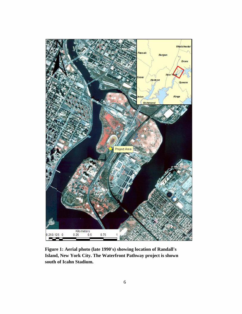
Figure 1. Aerial photo (late 1990's) showing location of Randall's Island,
New York City. The Waterfront Pathway project is shown south
of Icahn Stadium.…………………………………………………..
6
Figure 2. Detail of footprint of Waterfront Pathway project………………… 7
Figure 3. Overview of Randall's Island, Little Hell Gate and Wards Island… 11
Figure 4. Field view of the remains of Little Hell Gate at the southwestern
section of the project impact area…………………………………..
12
Figure 5. Sequential shoreline modifications, 20th
century………………….. 14
Figure 6. Superposition of Waterfront Pathway project footprint showing
landforms, land use, and physiographic features on 1851 map of
Randall’s Island. Locations of the boreholes are depicted……….
15
Figure 7. Project area with core locations (please note: the boundaries
depicted are not to actual scale)..…………………………………..
27
Figure 8. Stratigraphic profile of the project area’s southern section………... 28
Figure 9. Stratigraphic profile of the project area’s northern section………... 29

3
List of Tables
Table 1. List of Core Descriptions………………………………………... 30

4
Chapter 1 – Introduction and Objectives
The New York City Economic Development Corporation (NYCEDC) has proposed
construction of a Waterfront Pathway within a portion of land along the southern coast of
Randall’s Island in Manhattan, New York (Block 1819, Lot 203) (Figure 1 and Figure 2). The
project area is located south-southwest of the Icahn Stadium and the Triborough Bridge, and
directly north of a marshy lowland, a remnant landscape feature of the tidal channel formally
known as Little Hell Gate. This report addresses the results of a Phase 1B archaeological
assessment of the projected impact area of a Waterfront Pathway proposed by the New York
City Economic Development Corporation.
The New York City Landmarks Preservation Commission (LPC) requested that a Phase 1B
archaeological sensitivity assessment be conducted for the proposed site of the waterfront
pathway the project area (LPC File Name 27671_FSO_ALS_05062011.doc; Figure 1). Prior
studies on the systematic development of Randall’s Island have documented chronologies and
patterns of general landscape change and land-use over the course of prehistoric and historic time
frames (Schuldenrein et al.: 2008; Bergoffen 2001; Rutsch and Porter 1980). These
investigations have identified areas of archaeological sensitivity in the vicinity of the project
area. Typically, however, the earlier investigations did not focus on the specifics of landform
alteration and subsurface disturbance (although see Schuldenrein et al., 2008 for a discussion of
landform relations). In the proximity of the present project footprint, a portion of the terrain
directly southwest of the Triborough Bridge and Icahn Stadium was determined to have high
potential for containing human burials and yard features related to the early historical
development and occupation of the island.
LPC approved a geoarchaeologically based investigative strategy for testing the project area
on May 6, 2011. Consistent with recommendations from earlier reports and archives, LPC
concurred with recommendations that this location had potential to contain archaeological
resources associated with a 19th century Potter’s Field (graveyard), and that this feature
potentially housed the remains of hundreds if not thousands of human bodies (Bergoffen 2001;
Rutsch and Porter 1980).
Descriptive accounts of the Randall’s Island Potter’s Field were widely referenced in 19th
century accounts and newspapers until that facility’s closure in the mid 1850’s. However neither
documentary evidence nor limited archaeological testing furnished any indications of the precise
location of burials. The geoarchaeological testing effort by Geoarcheology Research Associates
(GRA) in July, 2011 attempted to assess the integrity, antiquity, composition and preservation

5
potential of subsurface deposits that might be diagnostic of historic resources, and more
specifically, mobilized sediments housing or burying human remains. A corollary objective was
to test for intact Holocene sediments and paleoenvironmental features that would register
potential prehistoric contexts. Field relations and known local sequences converged around the
possibility of encountering estuarine and tidal stream sediments dating to 5000 years Before
Present (B.P.) beneath stratified (and dateable) historic fill successions. The latter would have
sealed in the former tidal strait between Randall’s and Wards Island, known as ―Little Hell Gate‖
and could conceivably furnish indications of large scale earth moving operations consistent with
the operations of a historic graveyard. Rutsch and Porter’s (1980) study of this portion of the
island provided broad outlines of terrain modification to the southeastern coastline and indicated
that the historic and prehistoric geography of this portion of the island differed significantly from
that of the present.
6
Figure 1: Aerial photo (late 1990's) showing location of Randall's
Island, New York City. The Waterfront Pathway project is shown
south of Icahn Stadium.

7
Figure 2: Detail of footprint of Waterfront Pathway project
The geoarchaeological testing program utilized a Geoprobe for limited subsurface testing to
develop a site-specific model of archaeological and historic sensitivity. Even such baseline
testing, that involved the distribution of 2-3‖ diameter boreholes aligned within the perimeters of
the project boundaries, could furnish broad outlines of landform history (both locally and
regionally). Detailed examination of recovered sediment matrices could be linked to natural vs.
anthropogenic depositional agencies and general sequences can structure histories and preview
landscape and land use chronologies. Historic maps and accounts (Bergoffen 2001) showed that
the earliest documented setting was on the margins of an orchard in the early eighteenth century.
The site occupied the shoreline of a tidal channel until the mid 20th century. Accordingly,
recovery of subsurface deposits could inform on the transformation of the coastal setting and
register indications of human landscape modification over a 200 year period, and probably
earlier, with probes extending well into the thick, regionally expansive marsh-peat deposits that
date to <5000 B.P. near their basal stratigraphic contacts.
The subsequent narrative of this study begins with a detailed overview of the environmental
setting under investigation (Chapter 2). The historic development of the project area is then
presented (Chapter 3) and is succeeded by a detailed account of the investigative methodology of

8
the field effort (Chapter 4). In general, the methodology was designed to test for the presence vs.
absence of intact subsurface deposits, to distinguish fill sequences, and to establish the
depositional origins of pristine landscape elements if, indeed, these were present. Results and
interpretations of the subsurface probing are discussed in Chapter 5. A concluding section
(Chapter 6) synthesizes geoarchaeological results and interpretations, ultimately offering
recommendations bearing on a significance determination.
Four critical objectives were targeted in the present deep testing program:
1. Determining depth and extent of historic and sub-recent landfilling;
2. Isolating intact portions of the Potter’s Field cemetery and House of Refuge;
3. Exposing elements of the pre-19th
century cultural and natural landscape;
4. Identifying contexts for prehistoric sites and Holocene paleo-environments

9
Chapter 2 – Environmental Setting
Section 2.1 Geological Setting, Land Filling and Modern Topography
Randall’s Island is located east of Manhattan, south of the Bronx, and west of Queens. The
island is formally part of the borough of Manhattan and is located at the confluence of the
present day Harlem River and East Rivers, with Hells Gate situated directly to the northeast.
Randall’s Island was once separated from Wards Island and Sunken Meadows by the ―Little Hell
Gate‖ tidal strait. The eventual infilling of the Little Hell Gate channel merged the land bodies of
Randall’s Island, Ward’s Island and Sunken Meadows into a single landform. Prior to infilling
Randall’s Island proper consisted of approximately 145 acres while Wards Island spanned nearly
240 acres. Currently the land mass referred to as Randall’s Island occupies approximately 530
acres (Bergoffen 2001). The project area of the 2011 field investigations extended along the
southwestern coastline, effectively the former shoreline of Little Hell Gate.
To the north, the island was divided from the Bronx by variously migrating (anastomosing)
channels known as the Bronx Kill or Kills. The Bronx Kill was once nearly as wide as the East
River at 125th Street, but only a narrow strait remains. The East River flows around the island
and the western branch forms the Harlem River. The treacherous bend southwest of Wards
Island is called Hell Gate. An 1851 United States Coast Guard map depicts a complex of large
rocks and boulders which would have rendered the Hell Gate passage a notorious navigational
hazard (Schuldenrein et al. 2008: 8).
Randall’s Island is situated in the New England Upland physiographic region, a division of
the Appalachian Highlands. The region has two geologic projections, or prongs, extending
southward. The smaller and more easterly is the Manhattan Prong which includes Randall’s
Island (Rutsch and Porter 1980: 4). That feature is composed of igneous and predominantly
highly metamorphosed bedrock which extends to the southern tip of Manhattan Island (Rutsch
and Porter 1980: 4; Schuberth 1968: 10).
The stratigraphy of the project area was synthesized on the basis of bedrock geological
mapping, surficial geology maps, and historical background research that were subsequently
tested by the geoprobe field program. The bedrock of the Randall’s Island is characterized by
four primary rock groups (Schuldenrein et al. 2008). The majority of the island is underlain by
the Manhattan Schist (Єm), a grey, layered sillimanite-muscovite-biotite-kyanite schist,
interfingered with stratified tourmaline-garet-plagioclase-biotite-quartz schist and gneiss with
black amphibolites layers (Baskerville 1994). The Manhattan Schist cuts across the proposed site
of the waterfront pathway. Another bedrock unit prominent along the central and eastern sections

10
of the island is the Inwood marble (OЄi), which is banded and consists of a white or blue gray
calcitic dolomite. The east coast of the island is dominated by the Fordham Gneiss (Yfb), locally
dominated by a black and white banded facies. The black bands are comprised of quartz,
plagioclase and biotite while white bands consist of garnet, quartz, plagioclase, muscovite and
microline. The northwestern edge of the island is also comprised of a member of the Fordham
Gneiss group; this member is a medium gray fine grained quartz, with biotite, plagioclase, and
muscovite-quartz granofels. The schist is interfingered with gray biotite, muscovite, and quartz;
granofels layers are thin and fissile. Intrusions of course white granite and granite pegmatite are
common and often found nearest to the point contact with the adjacent geological unit
(Baskerville 1994).
As noted, the surfaces of both Randall’s and Ward’s Islands have been extensively modified
by development during the historic period. Accordingly, the surficial geology (and land cover) of
Randall’s and Ward’s Island’s is mapped entirely as fill (Schuldenrein et al. 2008; Cadwell
1991). Prior to historical landform modification the island’s topography would have been
undulating and rugged, conforming to the configurations of Pleistocene-age glacial advances and
retreats that left expansive till plains and moraine-like features. Only residual patches of these
tills are preserved regionally and evidence of their presence is discontinuous on Randall’s Island.
Where present, till bodies consist of heterolithic gravels, sands and clays. The surface soils of
the project area invariably incorporate disturbed till matrices. Formally they are mapped as the
Inwood-Laguardia-Ebbets complex of deep debris and rubble mixed with natural soil. The
matrix is dominated by coarse fragments or rubble and gravels (New York City Soil Survey Staff
2005).
The earliest accounts of Randall’s Island describe terrain that was largely swampland
punctuated by raised bedrock (ie., granite) hills (Richmond 1872: 562). That landscape was
particularly pervasive along southeastern end of the island, where marshlands marked the
transition to the near shore environment. During the mid-19th century, when various charitable
institutions were being constructed, the island’s southern tip was dotted with farms and orchards
(Schuldenrein et al. 2008). At that time, outcrops of bedrock and larger reefs along the western
shoreline affected tidal movements unpredictably, presenting a severe navigational hazard to
mariners. To expand shipping lanes and facilitate navigation, a series of bedrock excavations
were undertaken to widen the channels and gave rise to the florescence of the shipping industry
during the late 19th and 20th centuries. The blast rubble obtained through these excavations was
likely used for local land rehabilitation and reclamation projects on the island. Over the long-
term episodic coastline engineering and land reclamation projects account for the existing
shoreline configurations and topographies (Rutsch and Porter 1980, 8).
In 1938, one of the largest of these landscaping efforts resulted in the infilling of the
waterways that separated the islands from each other and from the Bronx. As noted, nearshore
landfills attenuated the east branch of the East River. Two seawalls were initially extended

11
northward from the northeast point of Ward’s island and from a point near the Hellgate Bridge.
These seawalls eventually encircled the island to the east (Sunken Meadow) and formed the
boundary of the landfill. In the 1990’s a major landfilling effort expanded the swampy terrain
between the Triborough and the Hell Gate Bridges where a footbridge once existed. Currently,
only a narrow inlet directly south of the project area is all that remains of Little Hell Gate (Figure
3; Figure 4; see Schuldenrein et al. 2008: 8; Bergoffen 2001: 4).
Figure 3: Overview of Randall's Island, Little Hell Gate and Wards Island

12
Over the course of the 20th century, larger scaled development, changes in land-use and
episodes of infilling produced extensive and thick accumulations of fill across much of Randall’s
Island. Stratigraphically this is registered by variable depths and distributions of landfill that cap
earlier (Holocene-age) estuarine peats, tidal sands and silts. The overall extent of near shore land
reclamation can be seen in Figure 5 which depicts the changes to the southwestern shoreline
(upper island segment) between 1903 and 1975. It can be seen that in the early 20th century
collective shoreline modifications produced an undulating terrain. By the mid 1970’s the
contemporary configurations of shorelines were largely in place.
Figure 6 illustrates the degree to which 150 years of discontinuous landscaping and land use
engineering reconfigured the topography of the Randall’s Island. The project impact area, in
particular, is situated on what was formerly a graded upper bedrock surface inter-graded with a
veneer of coastal deposits. The coastal margins apparently sustained seasonal marshes. An
orchard once occupied the terrain extending to the near shore, although the source sediments
supporting the orchard have subsequently been removed (by extensive relandscaping; see
Figure 4: Field view of the remains of Little Hell Gate at the southwestern section
of the project impact area.

13
Chapters 5 and 6). The northern section of the project footprint would have been onshore while
the southernmost sections would have straddled the interface with offshore sediment.

14
Figure 5: Sequential shoreline modifications, 20th
century

15
Figure 6: Superposition of Waterfront Pathway project footprint showing
landforms, land use, and physiographic features on 1851 map of Randall’s
Island. Locations of the boreholes are depicted. (The project tract was once an
orchard at the edge of the former coastal zone of Randall's Island proper. Note
buildings on the northwestern edge of the project area, probably related to the
orchard. Areas on the east are shown as marsh basins, while the south coast is
fronted by near-shore sands.)

16
Section 2.2 Modern Setting
The most prominent development project on Randall’s Island over the past century was the
erection of the Triborough (currently RFK) Bridge and connecting railroad bridges. The
Triborough Bridge, which first opened in 1938, extends from Manhattan to Randall’s Island,
lineally and approximately parallel to the northern side of the island. Topographic maps which
indicate that a bedrock ridge running parallel to the northern end of Manhattan provided the
basal foundation for the Triborough Bridge. While the Triborough Bridge establishes the island’s
eligibility for listing on the National Register of Historic Places, the proposed project will have
no impact on the Triborough Bridge (Schuldenrein et al. 2008).
Parallel to the Triborough Bridge is the New York Connecting Railroad Bridge (built
between 1914-17), which crosses Randall’s Island from the Bronx and then diverges from the
Triborough to cross Hell Gate as the Hell Gate Bridge. A footbridge once spanned Little Hell
Gate between the Triborough and Hell Gate Bridge (Schuldenrein et al. 2008). Other structures
on Randall’s Island include the offices and shops of the Triborough Bridge and Tunnel
Authority, and Icahn Stadium. The facilities for the New York City Fire Department Training
Academy and the Department of Environmental facility dominate Randall’s Island southeastern
coast. The southwestern quarter of Randall’s Island contains extensive undeveloped tracts,
parking lots and recreational parklands.
Subsurface probes have thus far furnished only limited information on developmental
impacts to the island’s natural and earlier historic landscape. Soil borings taken near the
Manhattan Toll Plaza at the north of Randall’s Island in conjunction with the Triborough Bridge
Rehabilitation Project recorded a pristine surface elevation of 15’ (4.5 m), the top 5’ (1.5 m) of
which consisted of miscellaneous fill. Below the fill, lenticular clay-silts interbedded with fine
sands and silts indicated limnic and lacustrine sedimentation. Select borings from the northern
end of Randall’s Island (the area currently used for recreational school fields) penetrated fills
ranging in depth from 13-30’ (4-9 m). Taken together, the probe records indicate that fill depths
vary appreciably across the island, such that preservation potential for natural stratigraphy in
select reaches of the island is high. Finally, shallow stratigraphic profiles from the test pits
excavated by Rutsch and Porter (1980) furnish supplementary subsurface information to assist in
the reconstruction of the sequences.

17
Chapter 3 – Historical Background
Section 3.1 Prehistoric Period to the Mid-19th Century
Prehistoric Period
The map of inventoried prehistoric archaeological sites compiled by the Office of Parks,
Recreation and Historic Preservation (OPRHP) records no prehistoric sites for either Randall’s or
Ward’s Islands (Bergoffen 2001; Schuldenrein et al. 2008). Preliminary indications are that
Randall’s Island was largely unsettled during the historic period. In contrast, archival records
show that there was considerable Native American activity along the adjacent Manhattan
waterfront and in Queens County right across from Randall’s Island.
Historical Perspectives Inc. (HPI 2001:11) undertook a comprehensive background study
within one mile of the project area (Historical Perspectives 2001: 11) and documented the
following sites:
NYSM#4064
This a campsite identified by Parker (ACP-NYRK no#) on the Manhattan shore of the
Harlem River in the vicinity of the approaches to the Triborough Bridge, about 1,000 feet (0.3
km) northwest of the study lot.
NYSM#5475; OPRHP #A005-01-0027, #A005-01-0031
This is a village site (previously referenced), identified by Reginald Bolton as Ranachqua
The NYSM and OPRHP locate the site(s) more generally than does Bolton, in a broad area south
of 133rd Street. It extends as far west as the Bruckner Expressway, about 2,600 feet (0.8 km)
northwest of the study site.
NYSM#7248
Traces of occupation (small numbers of artifacts) were recorded on site, approximately 1.0
miles (1.6 km) west of the study lot on the Manhattan shore of the Harlem River, near Park
Avenue.

18
NYSM#4539 (ACP Quos 00#)
Here shell and kitchen middens, or refuse heaps, were concentrated along the East River
shore, in what is now Ralph Demarco Park (north of Astoria Park), in the Ditmars area of
northwestern Queens, about 3,000 feet (0.9 km) southeast of the project site (Parker 1920: 672).
These sites are clustered along the shores of major waterways, the Harlem, Bronx and East
Rivers, and surround the project area in all directions. At the above sites there were shellfish
beds which could have been exploited in addition to marshland resources, and small freshwater
creeks. The project area featured a similar distribution of ecological resources. Although there
were no freshwater creeks on the island, early maps indicate the existence of at least two small
ponds which may have served as fresh water sources and tidal wetlands along the northern and
western coastlines of Randall’s Island at least until the late 19th
century (Historical Perspectives
2001; see Appendix A, Maps 1-5)
Given its analogous ecological setting and proximity to these prehistoric sites, it is somewhat
unusual that no inventoried prehistoric archaeological sites have been recorded on Randall’s or
Wards Islands. However, given the strong evidence for local prehistoric occupation and
advantageous and similar ecological settings and resource availability, the project area should be
considered to have high potential for containing subsurface prehistoric remains. However, given
the generally shallow depths of these deposits (i.e., within 3 to 4 feet [1.0-1.5 m] beneath the
predevelopment surface), it is highly possible that historic regrading and filling could have
decimated prehistoric remains (Historical Perspectives 2001: 8).
Early Historic Period
Since its original sale to the Dutch Governor in 1637, the island’s name has reflected its
various landholders or tenants. The Mayrechkeniockkingh Indian Chiefs, Seyseys and Numers,
sold Ward’s Island (which they-called Tekenas) to Wouter Van Twiller in 1637. The translation
of Tekenas is uncertain. However, several meanings are possible including forest, uninhabited
track, and wild land (Schuldenrein et al. 2008 and references).
Twiller used Ward’s Island only to graze livestock though he did not reside there. His
cowherd was the Danish farmer Barent Jansen Blom who earned the nickname Groot Barent or
Great Barent. The first European names of both Randall’s and Ward’s Islands were based on this
man’s name: Great Barent Island for Ward’s; Little Barent Island for Randall’s. Those names
were corrupted to Great and Little Barnes or Barn Island(s), and in the 1730 Montgomerie
Charter, Ward’s Island appeared as Great Barn Island.
The English appropriated Ward’s Island from the Dutch States General and in 1664 awarded
it, along with Randall’s Island, to Thomas Delavall of Harlem (d. 1682), a collector of customs.
Thomas Delavall left his land to his son-in-law William Dervall. In 1687, Thomas Parcell bought

19
Ward’s Island and it remained in his family for 75 years. It was also then called Parcell’s Island.
In 1767, Thomas Bohanna purchased land here and briefly gave his name to the island
(Schuldenrein et al. 2008: 10).
During the Revolutionary War, Ward’s Island was occupied by British troops who
designated for use as an army base. Both islands were contested during the conflict and control
over them was transferred from the Continental Army—George Washington established a
smallpox quarantine on Randall’s Island in the spring of 1776—to the British who drove the
Americans out in September of that year.
Subsequent to the acquisition of Randall’s Island and Sunken Meadow from the heirs of John
Randel in 1835, New York City began to purchase large tracts of Ward’s Island by a series of
conveyances from 1851-52 and 1855.
Historical maps and documentary evidence indicate that Randall’s Island did not undergo
substantial development until the mid-19th
century. This applies to the project area as well.
According to the 1836 Colton map farm houses were constructed at around this time in
conjunction with the growth of orchards on the southern section of Randall’s Island (see
Appendix A; Map 3).
Section 3.2 History of Randall’s Island from the mid-19th Century to the Present
Randall’s and Wards Island share similar histories over the past 150 years. During the mid-
nineteenth century both islands had established burial grounds and institutional facilities. The
emergence of these facilities is critical to this study since the present testing project was keyed to
encountering deposits from them. They included the Potter’s Fields, the House of Refuge, and
the construction of the Triborough Bridge and related infrastructure systems.
Potter’s Fields
In the early Euroamerican period, a potter’s field was the burial place for the poor, the
unknown, and the unclaimed dead (Bergoffen 2001: 13). By colonial times, poor African slaves,
freedmen, ―indigent whites‖ and people of Jewish faith buried their dead on the outskirts of
town, commonly near the potter’s workshops and tannery yards. In 1835 Jacob Lorillard
petitioned to the city council that the pauper’s burial ground, which had been previously
relocated, be moved again to Randall’s Island, which originally had been purchased by the city
for this purpose (Bergoffen 2001:13; Klips 1980: 542).
Plans for a burial ground on Randall’s Island passed the City Council in 1843 (Bergoffen
2001:14; Klips 1980: 542). The earliest accounts detailing the potter’s field on Randall’s Island

20
also provide evidence of its likely location within the landscape. One account given by the Alms
House Governors in 1850 details the burial ground and states:
[The] field is upon a rock below the surface, so that the decomposition of human remains
there interred, and the effluvia resulting from it will not sink in the ground, but the latter will
exhale and taint the atmosphere. It’s proximity therefore to the Nurseries…is objectionable, and at
certain season dangerous (Bergoffen 2001:14; Alms House Governors 1850).
Such evidence suggests that the potter’s field may have been located in proximity of shallow
bedrock, a setting consistent with the topography of the island’s southern coastline. The grounds
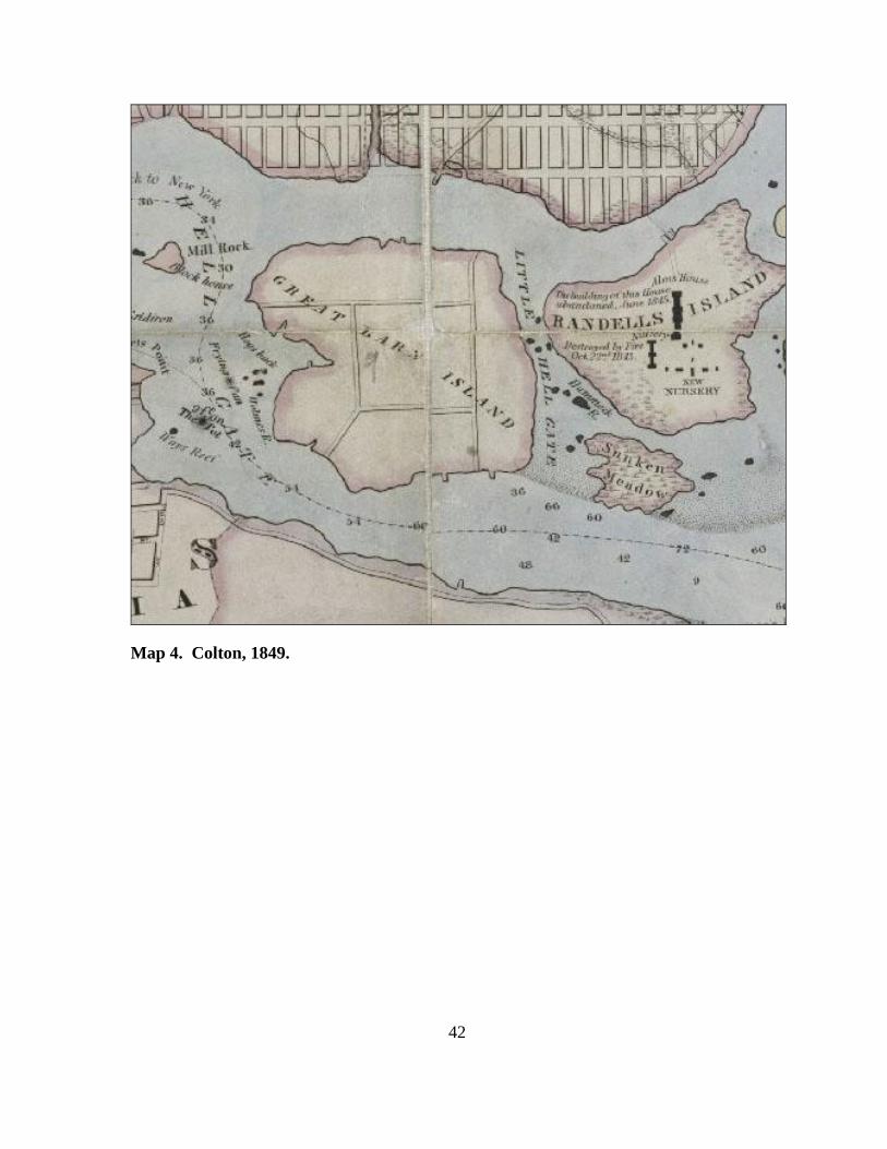
are also described as being in the vicinity of a nursery. The Colton 1849 map depicts two
nurseries on the island; one is labeled the ―New Nursery‖ and the other is labeled ―Nursery‖,
with a note detailing that this building was destroyed in a fire on October 22, 1843 (see
Appendix A; Map 4).
While historic maps or plans do not provide detail for the exact location of the burial ground,
contemporary studies suggests that the potter’s field on Randall’s Island was located south of the
nurseries. Specifically, they would appear to have occupied the hillside above the marshy ground
at the southeastern edge of the island (Bergoffen 2001:14). This location would have brought it
very close to the nursery, within less than 300 feet (100 m) of the southernmost building of that
complex. Bergoffen (2001) concluded that if the potter’s field had been situated here the
construction of the Triborough Bridge or the installation of utility pipes and conduits would most
likely have disturbed burials within the footprint of the potter’s field. However there is no record
of any burials found in this area, and it is unlikely that the cemetery was located west of the
marsh because the House of Refuge was built there in 1854 (Geismar 2002, 1).
The Burial Ground for Paupers as it was called at the time was in 1854, in a New York Times
article, described as:
―…consisting of long and deep trenches, into which the pine coffins were packed directly on
top of each other, without a spadeful of dirt between them to the high of seven, eight, and nine
feet….and were never covered until the line had been completed‖ (Unknown 1854).
These observations converge around the strong possibility that burials to depths of 7-8 feet
(2-3 m) could be encountered either beneath or within fill sediments in the area of the project
footprint. No further specifications or markers are documented in the literature that had been
examined in the baseline study (Bergoffen 2001). Somewhat more speculative indications of
burial preservation is presented for the area west of the (Triborough) Bridge and continuing
south for approximately 200 feet to the edge of the original shoreline (Bergoffen 2001: 19).
A significant anomaly was noted during the construction of the Triborough Bridge. In 1935 a
set of disarticulated human bones were found at the southern end of the island during
excavations for Pier 37 North. This is the second to last row of piers on Randall's Island,

21
approximately 150 feet south of Downing Stadium (Bergoffen 2001: 15) . However there is no
information about the number or kind of burials discovered here, and they could have been
individual interments, perhaps unrelated to the potter’s field, sensu stricto (Bergoffen 2001: 15).
The project footprint extends approximately 32 to 318 ft south of Icahn Stadium, and
therefore related development should be considered highly sensitive for human remains. Most
recent research (i.e. Bergoffen 2001; Geismar 2002) proposes that the only area on Randall’s
Island large enough to have housed the graveyard is the southern tip, south/southwest of
Downing Stadium. Bergoffen’s (2001) projections of archaeological sensitivity on Randall’s
Island identified the area west of the Triborough Bridge extending ca. 200 ft (60 m) and parallel
to the coastline as being the high probability zone.
House of Refuge
The House of Refuge was built to the west of the burial ground and was formally situated
immediately northwest of the project area (see Geismar 2002: Figure 6). Opened in 1851, the
House of Refuge was appropriated by the Society for the Reformation of Juvenile Delinquents as
a reformatory for wayward boys and girls. The Society was an outgrowth of the 19th-century
movement to transform prisons from places of punishment to places of penitence and reform.
The society originally acquired ten acres for the development of the institution, decided the 10
acres was too small a tract, and in 1851 the society acquired 36.6 acres from the city.
Construction on the complex began in 1852 and took two years to complete. Rutsch and Porter
(1980) note that during construction a considerable amount of blasting and grading was needed
in order to prepare the southwestern corner for the construction of the complex’s foundation and
huge retaining walls.
The 1851 U.S.C. and G.S. map of Hell Gate and its approaches show four free-standing
buildings on the southwestern-most hill on the site of the House of Refuge, and it is probable that
these structures preceded the institution’s construction, as they are also present in the 1836
Colton map (see Appendix A, map 3; see also Historical Perspectives 2000: Figure 5). While
their actual purpose is unclear these are likely the vestiges of farmhouses along the southern
coastline. Since they appear on maps after c. 1836, they may also have been used by the staff of
the other institutions which preceded the House of Refuge on the island. However, it is likely
that these buildings were incorporated into the House of Refuge complex or destroyed during the
complex’s construction.
Maps and photographs dating after 1854 show a large, formally laid out complex of 3- to 4-
story brick buildings facing west toward the Harlem River and Manhattan Island, with the
important central and terminal pavilions capped by domes (see Appendix A, map 6). The area of
study also appears to have been regraded to form a flat expanse for the buildings and their
courtyards (Historical Perspectives 2000: 11).

22
While the society was privately managed it received substantial state support and was
subsidized by government controlled fees and taxes. At the House of Refuge, children received
four hours of religious and secular instruction each day. Religious instruction was strictly
evangelical Protestant. Roman Catholic clergy were excluded. In addition, there was 6~ hours of
"industrial employment", i.e., caning chairs and making shoes for outside contractors. Other
sources record the boys producing brushes and brass nails as well. Girls made uniforms, worked
in the laundry and did other domestic work. Some were eventually released to family members
or friends, but most were later indentured for supervised employment, the girls as housekeepers,
and the boys as farmers (Historical Perspectives, 2001; Seitz and Miller 1996:165; NYSARA,
1989: 5). Children who died while at the facility were interred at the Paupers burial ground on
Randall’s Island (Bergoffen 2001).
The facility was expanded in 1860. At this time the average population of inmates in the
complex was between 500 and 600, but nearly a thousand were placed there during the 1860s
and 70s. In 1857, the House of Refuge hosted a national convention of reformatory
administrators, and at the time, had the largest reformatory population in the United States
(Historical Perspectives 2001, 12). The New York State Committee on Social Agencies boasted
that the "New York House of Refuge is now in the extent of its operations, the greatest reform
school in the world" (Historical Perspectives 2001, 12; Seitz and Miller 1996: 165; NYSARA
1989:5).
By 1935 the House of Refuge was beginning to close due to obsolescence, and the society
began to dissolve. The new prototypical juvenile delinquent institution was expected to function
properly in a rural setting, and it was at this time that inmates at the house of Refuge were taken
to newer facilities in the state located in Bedford, Coxsackie and Warwick, New York. The four
main structures associated with the development and House of Refuge property were
subsequently demolished due to development and construction of later buildings.
The archaeological contexts of the House of Refuge were broadly addressed in a previous
study by Historical Perspectives (2000). They considered the possibility of preserved shaft
features that might have overlapped onto the western margins of the project footprint. They note
that shaft features were likely to have been located on the southwestern coastline. This is
exemplified in the study’s conclusion that:
―…because most of the complex was surrounded by a high fence or wall, shaft features would
have been concentrated within the fenced area to the east of the main Refuge building...This would
include an area extending approximately 350 feet east of the main Refuge building and about
1,050 feet south from its northern end, extending almost to the shore of the Little Hell Gate.‖
Triborough Bridge and Downing Stadium
The eventual closure and removal of the House of Refuge was a precursor to changing design
plans for Randall’s Island in the early 20th
century. In the 1930’s New York City’s Department
23
of Parks and Recreation, under the directorship of Robert Moses, undertook the construction of
the Triborough Bridge to link Manhattan, Queens, and the Bronx. Downing Stadium was built at
around the same time, opening in 1936. All evidence indicates that the rubble from the House of
Refuge had been incorporated into the general landfill and was associated with the regarded
effort for construction of these new facilities (see Historical Perspectives 2001: Figure 12). Part
of the massive landfill program at that time resulted in infilling to the east and south of the
project site, which not only connected Randall’s and Wards Islands, but increased the size of
Randall’s Island to 194 acres (from its original 120) by 1939 (Historical Perspectives 2001).
The development of the Triborough Bridge, Downing Stadium (now replaced), Ichan
Stadium and the necessary infrastructure could have had significant impacts on the project
footprint. The eastern edge of the project area lies directly parallel to the bridge, while the
northern boundary of the project area abuts the southern edge of Downing Stadium. In general,
the construction of Downing Stadium and the Triborough Bridge reconfigured local landforms,
principally, as noted, by expanding the size of Randall’s Island to the northwest and east of the
project area. The present investigations explored the degree to which these impacts were
registered in the specific fill sequences underlying the study zone.
Section 3.3 Summary of Land Use
Documentary evidence suggests that land use and construction activities during the 19th
and
20th
century most probably had effects on archaeological integrity. Preliminary indications are
that large facilities, specifically the Potter’s Field and the House of Refuge, would have been
variously disturbed. The extent of the Potter’s field disruptions are unclear; while the data
suggests that the House of Refuge was destroyed, elements of structures might remain intact, but
that the facility’s integrity was compromised and its vestiges were probably incorporated into the
regraded fill used to stabilize and construct the Triborough Bridge and Downing Stadium. It is
also probable that the uppermost fill, capping the primary Bridge Construction debris, contains
sediment bodies linked to late 20th
century and 21st century regrading attendant to maintenance
and support of more recent support facilities.
Despite the likelihood for disturbance to the project footprint, immediately adjacent to Ichan
Stadium, there remains a high potential for the preservation of undisturbed resources in the
southernmost and eastern section of the Waterfront Pathways project area. The southern and
eastern sections of the project area do not have a history of being developed. Rather these areas
should preserve a deep record of 19th
and 20th
century infilling. Such contexts offer strong
potential for preserving archaeological and environmental resources in these sections of the
project footprint. There is a moderate-high potential for finding remains of the Potter’s Field, and

24
moderate potential for locating 19th
century shaft and cistern features related to the earliest
construction of the House of Refuge.

25
Chapter 4 – 2011 Survey and Methodology
The basis for this work plan was a previously developed archival map study or Phase 1A
assessment (Schuldenrein et al., 2008) and a Phase 1B Field investigation of Ward Island
(Schuldenrein et al., in preparation). The Phase 1B testing effort was a geoarchaeological
investigation that utilized geoprobe subsurface explorations to establish the composition of the
substrate in discrete landscape settings across the island. In particular, that field effort
characterized and mapped the subsurface distributions of various fill complexes and more limited
sequences of paleo-environmental (ie., prehistoric age) deposits. That study is still in preparation,
but the sediment complexes could be correlated with the remains of historic structures and older
landscape elements.
By coupling the island-wide archival and field assessments, it was possible to formulate a
measure of buried site potential, and archaeological sensitivity, based on ages and composition
of various fill and natural strata for discrete portions of the island (Schuldenrein et al., in
preparation). Preliminary overviews of the project area point to the setting of the Waterfront
Pathway’s extensions (from Broadway to the parking lot) on a somewhat unique setting on the
Randall’s island. It parallels the southern coastline, referenced as a potential site for the Potter’s
field and cemetery Bergoffen 2001). It also straddles the margins of the tidal straight between
Randall’s and Ward’s Island. Accordingly, there is a possibility for preservation of intact
estuarine and near-shore sediments beneath sequences of fill. The depths and composition of the
fill sequences themselves prior to this study was not known, but the Phase 1B probes previewed
significant thicknesses of multiple source grading materials (in excess of 10’ or 3 m). Further,
the characterizations of the fill might allow for separation and dating of source grading episodes,
through diagnostic artifacts, building rubble and debris.
The formal acceptance and implementation of a geoprobe-based subsurface testing strategy is
an extension of a consistent island-wide testing strategy. To sample stratigraphic sequences GRA
employed a Geoprobe® coring device to penetrate and extract stratified deposits. The geoprobe
had successfully penetrated the fill elsewhere across the island. It successfully established the
depths and contact interfaces between the near shore and tidal surfaces, as well as pre-contact
and prehistoric to historic surfaces. There is also an expectation that specific infilling episodes
and re-contouring efforts could be dated and integrated to the project footprint’s later history.
The geoprobe utilizes a hydraulic system to penetrate the subsurface and extract successive
and continuous lengths of 2-3 foot (0.6-1.0 m) long sediment columns. The device is highly
mobile and maneuverable across broad landscapes and where access is constrained by terrain and

26
vegetation. Two-inch (2‖) core sections were recovered in plastic sleeves and sealed upon
retrieval. At the conclusion of fieldwork, the samples were transported to the soil-sediment
facility at GRA where the sleeves were sliced open and arrayed vertically. Analysis involved
detailed soil and sediment descriptions following the criteria of USDA (1994) for soils and
NACSN (1983) for sediments. Sections of samples were arrayed sequentially and by depth from
the top of the column. Measurements of distinct layers established a vertical sequence of
deposition. Any and all archaeological materials encountered in the sediment were recorded,
photographed, and catalogued.
A laterally spaced series of these cores demonstrated variability of deposition within and
across the individual parcels. Depositional episodes could also be isolated. In general, the range
of historic disturbances was identifiable across the tested impact area and differing episodes of
fill were distinguishable. Evidence for pristine or natural (undisturbed) surfaces was identified in
a single core, RIWP-ARC-1. In this instance a thin, organically enriched alluvial sediment was
sampled and submitted for radiometric dating (Appendix C). It provided an age for the
stratigraphic interface between bedrock regolith and the initial episode of historic infilling. The
results of the field testing and core sampling are presented in the next section (Chapter 5).
The geoprobe excavations were undertaken on July 1, 2011. The original project design
called for the extraction of cores at seven (7) locations along the V-shaped designed pathways
(see Figure 6; Figure 7). A total of twelve (12) cores were procured since some boring locations
encountered bedrock at shallow depths. At five (5) locations deeper cores were emplaced
adjacent to the primary locations, these were relabeled with an ―a‖ (example: RIWP-ARC-2A).
Cores were judgmentally distributed to sample the terrain in representative manner and in
conjunction with pristine landform features (ie., shoreline) as mapped on historic projections.
The coordinates of core locations were recorded using a Garmin GPSMAP 60CSx unit. In the
field preliminary stratigraphic properties--sediment color, composition, and structure--were
described in the field, on the strength of known baseline subsurface relations from previous work
(Schuldenrein et al., in preparation).

27
Figure 7: Project area with core locations (please note: the boundaries depicted are
not to actual scale.

28
Chapter 5 – Results of Archaeological Testing
The alignment of the cores (Figure 7) was designed to illustrate changes in surface
topographies and subsurface stratigraphies in both the coastal and the interior high terrain
portions of the project footprint. It would therefore be possible to sample the project landscapes
in the most comprehensive fashion and to track how episodes of infilling have altered the terrain
since the 19th
century. Figure 8 documents surface and subsurface topographies for the near level
shoreline profile. It incorporates cores ARC-1, ARC-2A, and ARC-3. Figure 9 spans the
somewhat steeper transition between the islands interior to coastal margins, as registered in cores
ARC-6A, ARC-5A, and ARC-7A (Figure 9).
Figure 8. Stratigraphic profile of project area's southern section.

29
Figure 9: Stratigraphic profile of project area's northern section
The 1851 landscape map underscores the difference in landscape relations between the
interior settings and the coastline, with the projection of ARC-6A occupying a clear rise on the
distal (northern) portion of the project footprint and ARC-5A and 7A grading downslope to the
coastline (see Figure 6). The balance of the cores sampled proximal coastal locations. All cores
were emplaced to test for evidence of the historic features and the prehistoric paleo-
environments.
Detailed core profiles for the individual borings are presented in Appendix B, in the form of
photo composites and accompanying sedimentological tables. Table 1 is a comprehensive
summary of the sequence stratigraphy on a core by core basis. Comparisons between the coastal
and interior transect locations shows broadly similar depositional trends, with the primary
exception of the presence of a near shore facies at select locations grading towards the coastline
(Figure 9; ARC-5A and ARC-7A). The reason for the preservation of the near shore facies in

30
more distal interior locations and not in more proximal coastal settings (ie. the shoreline
locations depicted in Figure 8), as would be expected, is probably a reflection of landfilling
activity. Accordingly, extensive grading in the vicinity of the southern portion of the project
footprint resulted in complete stripping of prehistoric or early historic age sediments that would
have incorporated evidence for pristine near-shore sedimentation. Figure 8 shows that the
thickness of the fill along the southernmost portion of the footprint, reaches nearly 5 m, while the
fill cap is only 3 meters in the interior. Fill thickness is considerably greater to the south because
of the bedrock gradient, obviously, but the preservation of even minor depositional veneers of
the former shoreline at ARC-5A and ARC-7A demonstrates that the presumably deeper native
shoreline sediments to the south were completely removed over the course of historic grading
activities.
Table 1: Core Descriptions
Core Surface
Elevation (m)
Total
Depth
(cm)
Stratigraphy
RIWP-ARC-1 2.74
450 0-242 cm is fill; 242-244 cm is charcoal; 244-450
cm is weathered schist.
RIWP-ARC-2 2.74 450 0-397 cm is fill; 397-450 cm is weathered schist.
RIWP-ARC-2A 3.05 450 0-340 cm is fill; 340-450 cm is weathered schist.
RIWP-ARC-3 2.44 600 0-537 cm is fill; 537-600 cm is weathered schist.
RIWP-ARC-4 2.44 630 0-396 cm is fill; 396-594 cm are mixed fills and
estuarine deposits; 594-600 is weathered schist.
RIWP-ARC-5 3.35 300 0-136 cm is fill; 136-300 cm is weathered schist.
RIWP-ARC-5A 3.35 450 0-170 cm is fill; 170-232 cm are lacustrine
deposits; 232-450 cm is weathered schist.
RIWP-ARC-6 3.96 116 0-116 cm (entire core) is fill.
RIWP-ARC-6A 3.96 300 0-136 cm is fill; 136-250 cm is weathered schist;
250-270 cm is colluvium; 270-300 cm is
weathered schist.
RIWP-ARC-7 3.05 150 0-150 cm (entire core) is fill.
RIWP-ARC-7A 3.05 450 0-184 cm is fill; 184-215 cm are silty shoreline
deposits; 215-450 cm is weathered schist.
A minor stratigraphic slice of the pre-modification landscape may be preserved at ARC-1, in
the form of a thin (ca. 10-20 cm thick) lens of probable alluvial sediment that contained a
significant organic component. This may be an estuarine lens or the residuum of a historic tidal
channel. That sediment matrix was recovered and a sample was submitted for radiocarbon dating
(Appendix C). The radiocarbon assay produced a conventional radiocarbon age of 190±30 B.P.
(Beta-306085. 2 Sigma calibrated ages span the historic period (AD 1650-1690 to AD 1920-
1950). While the radiometric determination cannot be taken as conclusive evidence for the
presence of an intact component of the native environment, the sediment matrix that produced
the dated material was uniform and well sorted, indicating that it was undisturbed and thus,
probably a vestige of the original depositional locus.

31
Across the project area, subsurface probes reached depths ranging from 1.2 to 6.3 m (see
Table 1). Most cores extended beneath 3 m. The most dominant stratum of the subsurface
sequence was the historic fill which extended to the interface with schist bedrock in all cases
except in ARC-5A and ARC-7A, where shoreline sediments were found and in ARC-1, where
the estuarine matrices were identified. ARC-4 also produced an anomalous sediment that may
represent interfingering of older fill and an eroded estuarine surface. Collectively then, the
majority of cores verified that evidence for the prehistoric shoreline was largely removed by
historic regarding and excavation activities. In isolated instances thin, basal horizons of shoreline
and estuarine deposits were preserved.
Thus the most informative sediments consisted of the heterogeneous fill bodies, ranging in
thickness from 1.5 to 5.5 m. Detailed observations of the fills indicated that despite their non-
uniform composition, fills could be segregated on the strength of stratigraphic contacts and
boundaries and, in some instances, textural criteria (see Appendix B). For this study the
designation ―Ap‖ (formally designated as plow zone OR fill by NSSC (2002) was utilized to
distinguish fill. Discrete episodes of filling were offset by Arabic numeral preceding the ―Ap‖.
As many as 8 and as few as 2 fill units were preserved in the twelve cores sampled. It was not
possible to cross-correlate the fill types and individual units across the project footprint because
of the limited exposure of sediment properties visible within the 2-3‖ diameter core. Isolated
cultural materials were preserved within the fills and these were chiefly in the form of brick,
bone, cinders, shell, and glass. Relatively high concentrations of cultural materials were housed
in the upper and middle fills of ARC-1, ARC-2, ARC-3, ARC-4, and ARC-7A. These locations
conform to the eastern half of the project footprint. As in the case of the sediment matrix, the
core widths were too narrow to enable broad intra-site correlations.
Significantly, however, the parent matrices of the cultural fills with dense artifacts were not
homogeneous. A lack of uniformity in sediment texture and structure would indicate that the fill
strata represented admixtures of deposit from a variety of sources. They are not diagnostic of a
particular activity area, which would normally present fill matrices that are somewhat better
sorted and would contain parent materials of near uniform color and structural integrity. Thus the
sedimentological observations indicate that the fill matrix, inclusive of the artifacts, represents
mobilized fill materials that was dispersed across the landscape. That type of action represents
deliberate land-filling and would be most representative of regrading activity. While episodic
regrading may be in evidence within the individual cores, and more detailed analysis of
sediments might isolate the extent and possibly even the time frame of such regrading (through
microstratigraphic observations of the cores and correlation of glass and brick types) the net
result of such an effort would not result in any significant modification to the interpretation of
site formation process. It is conceivable that one, or perhaps more, of the eight filling episodes
might register clearance activities attendant to the dismantling of the House of Refuge.
Indications are that removal of support facilities for that structure may have occurred in stages

32
and the superposition of fills in within several cores is consistent with staged dismantling.
However, firm evidence documenting this particular activity could not be confirmed over the
course of this study.
Summarily, it was not possible to distinguish any unique fill type that offered indications of a
specific site location or land use history. No evidence that would confirm the presence of a
Potter’s Field was recovered and there were only minor suggestions that regrading might be
related to the leveling of the House of Refuge. Strata of prehistoric to early historic time frames
were recorded in isolated cores and these marked the interface of initial (historic) grading
activities.
33
Chapter 6 – Conclusions and Recommendations
Four primary objectives were targeted in the present geoarchaeological investigations for the
proposed Waterfront Pathway Project at Randall’s Island. The degree to which these objectives
were met and addressed is summarized below.
Determinations of Depth and Extent of Historic and Sub-recent Landfilling. This
investigation confirmed that historic and sub-recent fills underlie the entire project footprint.
These fills extend from 1.2 to 5.5 m in thickness. They represent episodic regarding episodes
dating back to the mid-19th
century. Discrete episodes of regarding can be identified but these
cannot be unequivocally linked to specific historic features on the property.
Isolation of the Potters Field Cemetery or House of Refuge. Structural elements of these
facilities could not be identified. It is probable that sediments related to the Potters field, in the
form of bone-rich matrix or sediments consistent with decomposing organic remains, would be
retrieved in the cores. These were not. It is probable that of the discrete fill types (n=8) some
may have been associated with leveling activities from the dismantling of the House of Refuge,
but it is not possible to confirm that correlation since identifiable building materials of the
facility were not recovered.
Exposure of elements of the pre-19th
century cultural and natural landscape. Evidence of
pristine strata (near shore deposits and estuarine/tidal silts) were exposed in several cores. Their
distribution was irregular and only the basal thicknesses of the natural horizons were preserved.
Most of the probes revealed contact between fill and bedrock confirming that across most of the
project footprint the intact shoreline and stream deposits were removed over the course of
relandscaping. In one case, evidence for a pre-modern stream/estuarine setting was dated
radiometrically.
Identifications of contexts for prehistoric sites and paleoenvironments. Pristine environments
existed on the project footprint but the only datable evidence provided a historic determination.

34
Prehistoric aged sediments included near-shore sands that did not contain radiometric material.
As noted, the distribution of landform elements of prehistoric age is discontinuous and
relandscaping has destroyed nearly all of the evidence beneath the present landfill cap.
Summarily, the subsurface investigations at the Waterfront Pathway project area did not
disclose preserved archaeological material of significance. Sustained disturbance has destroyed
most evidence of the prehistoric and historic landscape. The area should be considered
compromised from the perspective of cultural resources and planned development should be
allowed to proceed.

35
References
Alms House Governors
1850 The Governors of the Alms House. Copies available from 2nd Annual Report.
Baskersville, C. A.
1994 Bedrock and Engineering Geological Maps of New York County and Parts of
Kings and Queens Counties, New York and Parts of Bergen and Hudson Counties, New
York. United States Geological Society, New York.
Bergoffen, C. J.
2001 Triborough Bridge and Tunnel Authority: Triborough Bridge Rehabilitation
Project Randall’s Island and Ward’s Island, Manhattan, Phase 1A Archaeological
Assessment Report.
Bridges, W.
1811 This Map of the City of New York and Island of Manhattan. Peter Maverick, New
York.
Cadwell, D. H.
1991 Surficial Geologic Map of New York. In Map and Chart Series, New York.
Colton, J. H.
1836 City and County Map of New York. J. H. Colton & Co., New York.
1849 City and County Map of New York. J. H. Colton., New York.
Dripps, M.
1863 Map of New York and Vicinity. M. Dripps, New York.
Geismar, J. H.
2002 Randall’s Island, New York Amphitheater Sites Test Pits: Archaeological Report.

36
Historical Perspectives
2000 Randall’s Island Cultural Resource Assessment. Randall’s Island, New York, New
York.
Klips, S. A.
1980 Institutionalizing the Poor: The New York City Almshouse, 1825-1860. CUNY
Ph.D. University Microfilms., New York.
Letts, Sons & Co.
1883 New York. Letts, Son and Co., London.
National Soil Survey Center
1992 Field Book for Describing and Sampling Soils. Version 2.0. United States
Department of Agriculture, Natural Resources Conservation Service. Lincoln, Nebraska.
North American Commission on Stratigraphic Nomenclature (NASCN)
1983 North American Stratigraphic Code, 1983: American Association of Petroleum
Geologists Bulletin 67: 841– 875.
New York City Soil Survey Staff (NYSARA)
2005 New York City Reconnaissance Soil Survey. United States Department of
Agriculture, Natural Resources Conservation Service, NewYork.
Parker, Arthur C.
1920 ''The Archaeological History of New York," Part 2. New York State Museum
Bulletin, Nos.237 &238, September/October.
Rutsch, E. S. and Porter R. L.
1980 Stage One Cultural Resource Survey of the Proposed Storage Lagoon and the
Proposed Access Roadway Wards Island Water Pollution Control Plant, New York City.
Richmond, R. J. F.
1872 New York and its Institutions 1609-1872. E. B. Treat, New York.

37
Schuberth, C. J.
1968 The Geology of New York City and Environs. The Natural History Press, Garden
City, New York.
Schuldenrein, J. S., Mark A.; Malin-Boyce, Susan; Bergoffen, Celia J
2008 Phase 1A Archaeological Investigations for the Proposed Randall’s Island Field
Development Project.
Seitz, S. and S. Miller
1996 The Other Islands of New York City: A Historical Companion. The Countryman
Press, Woodstock, VT.
.
Taylor, W. L.
1879 The City of New York, New York.
Unknown
1854 The Wards Island Purchase, and the City Paupers. In The New York Times. The
New York Times, New York.
United States Department of Agriculture (USDA)
1994 Keys to Soils Taxonomy. USDA, Soil Conservation Service, Pocahontas
Press, Inc. Blacksburg, Virginia.
Viele, Egbert L.
1874 Topographic Atlas of the City of New York. New York: Ferd. Mayer & co.
Lithographers.

38
Appendix A: Historic Maps

39
Map 1. Viele, 1874. Map depicting original geography of New York with overlay of
contemporary street grid.

40
Map 2. Bridges, 1811.

41
Map 3. Colton, 1836.
42
Map 4. Colton, 1849.

43
Map 5. Dripps, 1863.

44
Map 6. Taylor, 1879.

45
Map 7. Letts, 1883.

46
Appendix B: Core Descriptions

47

48
RIWP-ARC-1
Unit
Depth
(cm)
Thickness
(cm)
Soil
Horizon
Munsell
Color Texture Structure Consistence Boundary Comments
Fill 0-87 87 Ap 10YR 2/1 VGS dist l c
Asphalt-gravels
and cinders; few
small bits of glass;
poorly sorted.
Fill 87-112 25 2Ap
2.5Y 4/2
2.5Y 4/4 SiCL dist fi c
2.5Y 4/2 (top) -
2.5Y 4/4 (bottom)
Fill 112-145 33 3Ap 10YR 2/1 VGS dist l c
Med. brick frags
throughout; bone
frags (130 cm and
142 cm); cinders.
145-217 72 4Ap 10YR 5/3 SiCL dist fri-fi n/a Poorly sorted.
217-242 25 5Ap 10YR 5/3 SiCL mass fri-fi s Poorly sorted.
Charcoal 242-244 2 6O 10YR 2/1 n/a n/a n/a s Charcoal layer
Bedrock 244-450 115 6Cr 10YR 4/6 SL gr fri n/a
5YR 4/6 - Fe stains;
weathered schist.
Texture: Si=silt; L=loam; C=clay; S=sand; F=fine; V=very; G=gravel; O=organic
Structure: 1=weak; 2= moderate; 3=strong; f=fine; m=medium; c=coarse
gr=granular; mass=massive; strat=stratified; sbk=subangular blocky; ab=angular blocky; pr=prismatic; cr=crumble
pl=platy; dist=disturbed/nostructure
Consistence: fri=friable; sl=slightly; v=very; l=loose; fi=firm; h=hard; st=sticky; ss=strongly sticky
Boundary Distinctness: a-abrupt; c=clear; d=diffuse; g=gradual; s=sharp
Boundary Topography: w=wavy; s=smooth; a=abrupt
Miscellaneous: n/a=not applicable
Fill

49

50
RIWP-ARC-2
Unit
Depth
(cm)
Thickness
(cm)
Soil
Horizon
Munsell
Color Texture Structure Consistence Boundary Comments
Fill 0-52 52 Ap 10YR 3/1 VGS dist l c Asphalt
Fill 52-98 46 2Ap 10YR 2/1 SiL dist fi c None
Fill 98-130 32 3Ap mixed GSiL dist l c
10YR 2/1 & 10YR 4/4 -
mixed; few small brick
frags.
Fill 130-230 100 4Ap 10YR 3/1 VGS dist l c
v. fine-fine shell frags;
poorly sorted; charcoal;
v. few brick and mortar
frags; v. few glass
frags; v. few bits of
animal bone.
Fill 230-300 70 5Ap 7.5YR 4/4 SCL mass fri n/a
Moderately sorted;
could be fill.
Fill 300-392 92 6Ap 10YR 3/4 SiCL dist fi c None
Fill 392-397 5 7Ap 10YR 2/1 SL dist l-fri s
Well sorted; v. few,
medium rock frags.
Bedrock 397-450 53 7Cr 7.5YR 4/6 GSL 2gr fri-vfi n/a
Weathered schist;
one subrounded clay
ball.
Texture: Si=silt; L=loam; C=clay; S=sand; F=fine; V=very; G=gravel; O=organic
Structure: 1=weak; 2= moderate; 3=strong; f=fine; m=medium; c=coarse
gr=granular; mass=massive; strat=stratified; sbk=subangular blocky; ab=angular blocky; pr=prismatic
pl=platy; dist=disturbed/nostructure
Consistence: fri=friable; sl=slightly; v=very; l=loose; fi=firm; h=hard; st=sticky; ss=strongly sticky
Boundary Distinctness: a-abrupt; c=clear; d=diffuse; g=gradual; s=sharp
Boundary Topography: w=wavy; s=smooth; a=abrupt
Miscellaneous: n/a=not applicable

51

52
RIWP-ARC-2A
Unit
Depth
(cm)
Thickness
(cm)
Soil
Horizon
Munsell
Color Texture Structure Consistence Boundary Comments
Fill 0-50 50 Ap 10YR 2/1 VGS dist l c Asphalt
Fill 50-79 29 2Ap 10YR 2/1 SiL dist fi c
V. few subrounded
rock frags.
Fill 79-97 18 3Ap
See
Comments VGS dist l c
Broken schist in 4 cm
round plates; white
rind w/ dark gray
middle; no matrix.
Fill 97-225 128 4Ap 2.5Y 4/3 GSiL dist fi c None
Fill 225-251 26 5Ap 2.5Y 4/3 SiL dist fi c None
Fill 251-269 18 6Ap 10YR 3/6 SiCL dist fi-slfi c
Mod-poorly sorted; 1
large (4 cm) flat rock
at base.
Fill 269-274 5 7Ap 10YR 6/8 VGS dist l c
Crushed rock; well
sorted.
Fill 274-340 26 8Ap 2.5Y 4/3 SiL dist fi c None
Bedrock 340-450 60 8Cr 10YR 5/8 GSCL gr fri n/a
10YR 3/3 - Fe stain;
at 422 cm rock fabric
is arragnged in a
horizontal fashion,
everything else
remains the same.
Texture: Si=silt; L=loam; C=clay; S=sand; F=fine; V=very; G=gravel; O=organic
Structure: 1=weak; 2= moderate; 3=strong; f=fine; m=medium; c=coarse
gr=granular; mass=massive; strat=stratified; sbk=subangular blocky; ab=angular blocky; pr=prismatic
pl=platy; dist=disturbed/nostructure
Consistence: fri=friable; sl=slightly; v=very; l=loose; fi=firm; h=hard; st=sticky; ss=strongly sticky
Boundary Distinctness: a-abrupt; c=clear; d=diffuse; g=gradual; s=sharp
Boundary Topography: w=wavy; s=smooth; a=abrupt
Miscellaneous: n/a=not applicable

53

54
RIWP-ARC-3
Unit
Depth
(cm)
Thickness
(cm)
Soil
Horizon
Munsell
Color Texture Structure Consistence Boundary Comments
Fill 0-115 115 Ap 10YR 2/1 VGS dist l c Petroleum smell
Fill 115-125 10 2Ap 10YR 4/4 SL dist slfri-l c F. coarse brick frags.
125-220 95 3Ap1 G1 6/N VGS dist fri-l n/a
Not gleyed (closest
color).
220-289 69 3Ap2 G1 6/N VGS dist l c
Not gleyed (closest
color).
Fill 289-300 11 4Ap 10YR 2/1 GSL dist l-slfi n/a None
Fill 300-424 124 5Ap 10YR 2/1 VGS dist l c None
Fill 424-440 16 6Ap 10YR 2/1 GSL dist l-slfi c
F. fine brick frags;
f. fine shell frags;
looks burned.
Fill 440-528 88 7Ap 10YR 2/1 SL dist fi-h n/a Crushed schist.
Fill 528-537 9 8Ap 2.5Y 4/2 SL dist l-slfi c
V. few gravel
inclusions; f. fine
brick frags.
Bedrock 537-600 63 8Cr 5Y 4/1 GSCL 3gr fri-l n/a
10YR 6/6 - Fe stains;
fill or fluvial -
(redeposited)?
Texture: Si=silt; L=loam; C=clay; S=sand; F=fine; V=very; G=gravel; O=organic
Structure: 1=weak; 2= moderate; 3=strong; f=fine; m=medium; c=coarse
gr=granular; mass=massive; strat=stratified; sbk=subangular blocky; ab=angular blocky; pr=prismatic
pl=platy; dist=disturbed/nostructure
Consistence: fri=friable; sl=slightly; v=very; l=loose; fi=firm; h=hard; st=sticky; ss=strongly sticky
Boundary Distinctness: a-abrupt; c=clear; d=diffuse; g=gradual; s=sharp
Boundary Topography: w=wavy; s=smooth; a=abrupt
Miscellaneous: n/a=not applicable
Fill
55

56
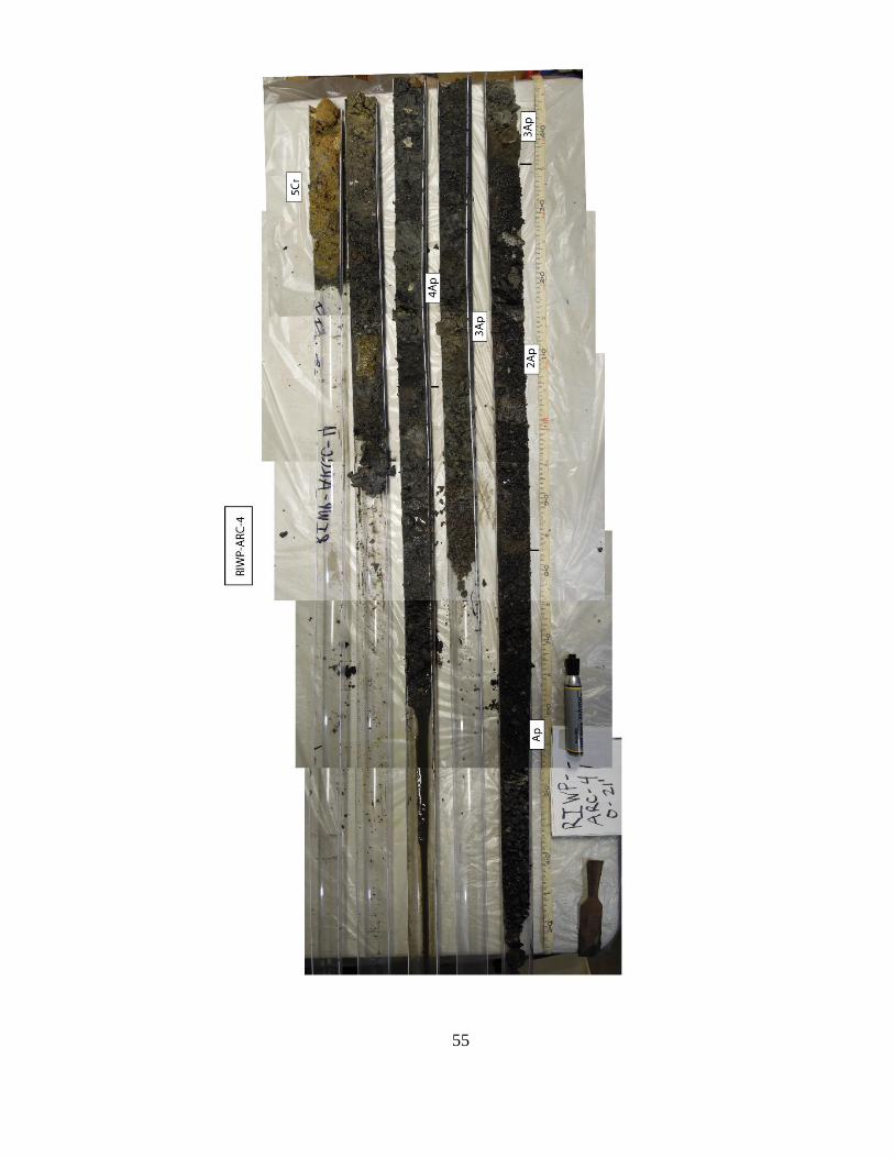
RIWP-ARC-4
Unit
Depth
(cm)
Thickness
(cm)
Soil
Horizon
Munsell
Color Texture Structure Consistence Boundary Comments
Fill 0-46 46 Ap 10YR 3/1 VGS dist c Asphalt
Fill 46-128 82 2Ap 10YR 2/1 GSiL dist l c Cinders; bone frags.
Fill 128-396 268 3Ap 10YR3/1 GSiL dist ss c
Common cinders;
glass frags - green
clear, amber; wood
frags; f. fine brick
frags; f. fine shells.
Estuary/Fill 396-594 198 4Ap 10YR 4/1 GSiL-CL dist ss c
few ceramic; v.f. shell
frags; possibly dist.
Estuary deposits.
Bedrock 594-630 46 4Cr 10YR5/6 GSCL gr fri n/a Weathered schist.
Texture: Si=silt; L=loam; C=clay; S=sand; F=fine; V=very; G=gravel; O=organic
Structure: 1=weak; 2= moderate; 3=strong; f=fine; m=medium; c=coarse
gr=granular; mass=massive; strat=stratified; sbk=subangular blocky; ab=angular blocky; pr=prismatic
pl=platy; dist=disturbed/no structure
Consistence: fri=friable; sl=slightly; v=very; l=loose; fi=firm; h=hard; st=sticky; ss=strongly sticky
Boundary Distinctness: a-abrupt; c=clear; d=diffuse; g=gradual; s=sharp
Boundary Topography: w=wavy; s=smooth; a=abrupt
Miscellaneous: n/a=not applicable

57

58
RIWP-ARC-5
Unit
Depth
(cm)
Thickness
(cm)
Soil
Horizon
Munsell
Color Texture Structure Consistence Boundary Comments
Fill 0-46 46 Ap 10YR 2/1 VGS dist l c
Few med. Brick frags;
asphalt
Fill 46-128 82 2Ap 2.5Y 5/2 SiCL dist fi c
F. highly weathered
rock frags.
Fill 128-136 8 3Ap 2.5Y 2.5/1 VGS dist l c
poorly sorted; Fe
concretion at base.
Bedrock 136-300 164 3Cr 2.5Y 5/3 GSCL 3gr fri n/a
Continued from
material above
(136-150 cm); Fe
staining toward
bottom.
Texture: Si=silt; L=loam; C=clay; S=sand; F=fine; V=very; G=gravel; O=organic
Structure: 1=weak; 2= moderate; 3=strong; f=fine; m=medium; c=coarse
gr=granular; mass=massive; strat=stratified; sbk=subangular blocky; ab=angular blocky; pr=prismatic
pl=platy; dist=disturbed/nostructure
Consistence: fri=friable; sl=slightly; v=very; l=loose; fi=firm; h=hard; st=sticky; ss=strongly sticky
Boundary Distinctness: a-abrupt; c=clear; d=diffuse; g=gradual; s=sharp
Boundary Topography: w=wavy; s=smooth; a=abrupt
Miscellaneous: n/a=not applicable

59

60
RIWP-ARC-5A
Unit
Depth
(cm)
Thickness
(cm)
Soil
Horizon
Munsell
Color Texture Structure Consistence Boundary Comments
Fill 0-45 45 Ap 10YR 2/1 VGS dist l c Asphalt
Fill 45-116 71 2Ap 2.5Y 4/3 SiL dist vfi-h s F. fine rock frags.
Fill 116-140 24 3Ap 10YR 2/1 VGS dist l c
Historic asphalt;
cinders; petroleum
smell.
Fill 140-150 10 4Ap 10YR 4/2 GSiL dist l n/a Poorly sorted.
Shoreline 150-232 82 5C 10YR 4/4 SiL 2gr fri-l n/a
Alternating bands of
matrix and weathered
schist.
Bedrock 232-300 218 5Cr1
2.5Y 7/1
2.5Y 3/1 m-cS 2gr fri-vfi n/a
300-390 10 5Cr2 SiCL 2gr fri-vfi g
390-420 30 5Cr3 SiL 2gr fri g
420-430 10 5Cr4 SiCL 2gr fri-vfi g
430-450 20 5Cr5 SCL 2gr fri n/a
Texture: Si=silt; L=loam; C=clay; S=sand; f=fine; m=medium; c=coarse; V=very; G=gravel; O=organic
Structure: 1=weak; 2= moderate; 3=strong; f=fine; m=medium; c=coarse
gr=granular; mass=massive; strat=stratified; sbk=subangular blocky; ab=angular blocky; pr=prismatic
pl=platy; dist=disturbed/nostructure
Consistence: fri=friable; sl=slightly; v=very; l=loose; fi=firm; h=hard; st=sticky; ss=strongly sticky
Boundary Distinctness: a-abrupt; c=clear; d=diffuse; g=gradual; s=sharp
Boundary Topography: w=wavy; s=smooth; a=abrupt
Miscellaneous: n/a=not applicable
Bedrock 10YR 4/4
Alternating, highly
weathered schist;
material darkens
towards bottom; few
rock frags. Fe stains-
10YR 5/6. Possibly
reworked material.

61

62
RIWP-ARC-6 0-4 ft only
Unit
Depth
(cm)
Thickness
(cm)
Soil
Horizon
Munsell
Color Texture Structure Consistence Boundary Comments
Fill 0-60 60 Ap 10YR 2/1 VGS dist l c Asphalt
Fill 60-88 28 2Ap 10YR 3/3 SiL dist vfi s None
Fill 88-91 3 3Ap 5YR 5/8 C dist vh s
Entirely composed of
a single brick frag.
Fill 91-104 13 4Ap 10YR 3/3 SiL dist vfi s None
Fill 104-110 6 5Ap 10YR 2/1 SiL dist fi s
Charred material;
bone fragment.
Fill 110-116 6 6Ap 10YR 4/4 SiL dist fri-l n/a
V. few coarse sub-
angular gravels.
Texture: Si=silt; L=loam; C=clay; S=sand; F=fine; V=very; G=gravel; O=organic
Structure: 1=weak; 2= moderate; 3=strong; f=fine; m=medium; c=coarse
gr=granular; mass=massive; strat=stratified; sbk=subangular blocky; ab=angular blocky; pr=prismatic
pl=platy; dist=disturbed/nostructure
Consisten
ce: fri=friable; sl=slightly; v=very; l=loose; fi=firm; h=hard st=sticky; ss=strongly sticky
Boundary Distinctness: a-abrupt; c=clear; d=diffuse; g=gradual; s=sharp
Boundary Topography: w=wavy; s=smooth; a=abrupt
Miscellaneous: n/a=not applicable

63

64
RIWP-ARC-6A
Unit
Depth
(cm)
Thickness
(cm)
Soil
Horizon
Munsell
Color Texture Structure Consistence Boundary Comments
Fill 0-53 53 Ap 10YR 2/1 VGS dist l c Asphalt
Fill 53-80 27 2Ap 2.5Y 4/2 SiL dist vfi s None
Fill 80-86 6 3Ap 2.5Y 6/3 VGS dist l s None
Fill 86-103 17 4Ap 2.5Y 3/1 VGS dist l c Historic fill.
Bedrock 103-300 197 4Cr
10YR 5/6
10YR 3/1 GSiCL 2gr fri-slfi n/a Weathered schist.
Texture: Si=silt; L=loam; C=clay; S=sand; f=fine; m=medium; c=coarse; V=very; G=gravel; O=organic
Structure: 1=weak; 2= moderate; 3=strong; f=fine; m=medium; c=coarse
gr=granular; mass=massive; strat=stratified; sbk=subangular blocky; ab=angular blocky; pr=prismatic
pl=platy; dist=disturbed/no structure
Consisten
ce: fri=friable; sl=slightly; v=very; l=loose; fi=firm; h=hard; st=sticky; ss=strongly sticky
Boundary Distinctness: a-abrupt; c=clear; d=diffuse; g=gradual; s=sharp
Boundary Topography: w=wavy; s=smooth; a=abrupt
Miscellaneous: n/a=not applicable

65

66
RIWP-ARC-7 Only 5 ft.
Unit
Depth
(cm)
Thickness
(cm)
Soil
Horizon
Munsell
Color Texture Structure Consistence Boundary Comments
Fill 0-90 46 Ap 10YR 2/1 VGS dist l c Asphalt
Fill 90-150 60 2Ap 2.5Y 3/2 SiL dist fi n/a
Historic fill; few brick
frags; few rock frags.
Texture: Si=silt; L=loam; C=clay; S=sand; F=fine; V=very; G=gravel; O=organic
Structure: 1=weak; 2= moderate; 3=strong; f=fine; m=medium; c=coarse
gr=granular; mass=massive; strat=stratified; sbk=subangular blocky; ab=angular blocky; pr=prismatic
pl=platy; dist=disturbed/nostructure
Consisten
ce: fri=friable; sl=slightly; v=very; l=loose; fi=firm;h=hard; st=sticky; ss=strongly sticky
Boundary Distinctness: a-abrupt; c=clear; d=diffuse; g=gradual; s=sharp
Boundary Topography: w=wavy; s=smooth; a=abrupt
Miscellaneous: n/a=not applicable

67

68
RIWP-ARC-7A
Unit
Depth
(cm)
Thickness
(cm)
Soil
Horizon
Munsell
Color Texture Structure Consistence Boundary Comments
Fill 0-78 78 Ap 10YR 2/1 VGS dist l c Asphalt
Fill 78-184 106 2Ap 2.5Y 4/2 C dist vfi c
V. few rock frags up
to 1 cm long; brick
frag on mortar.
Shoreline 184-202 18 2C1 10YR 6/4 Si mass l g
V. few subangular
gravels up to 4 cm
long.
Shoreline 202-215 13 2C2 5Y 6/3 SiL mass l s
Mod. sorted; f. sub-
angular rocks up to
5 cm long; common
v. fine shell frags.
Bedrock 215-450 235 2Cr
5Y 6/3
7.5YR 4/6
GSL-
GSiL 2gr fri-fi g
Weatherd schist; Fe
staining increases
towards bottom.
Texture: Si=silt; L=loam; C=clay; S=sand; F=fine; V=very; G=gravel; O=organic
Structure: 1=weak; 2= moderate; 3=strong; f=fine; m=medium; c=coarse
gr=granular; mass=massive; strat=stratified; sbk=subangular blocky; ab=angular blocky; pr=prismatic
pl=platy; dist=disturbed/no structure
Consisten
ce: fri=friable; sl=slightly; v=very; l=loose; fi=firm; h=hard; st=sticky; ss=strongly sticky
Boundary Distinctness: a-abrupt; c=clear; d=diffuse; g=gradual; s=sharp
Boundary Topography: w=wavy; s=smooth; a=abrupt
Miscellaneous: n/a=not applicable

69
Appendix C: Radiocarbon Dating Results

70

71

72