final report project #21 illumination and colour control
TRANSCRIPT

Page 1 of 36
Aalto University, School of Electrical Engineering
Automation and Electrical Engineering (AEE) Master's Programme
ELEC-E8002 & ELEC-E8003 Project work course
Year 2017
Final Report
Project #21
Illumination and colour control in flicker-free LED lighting
Date: 31.5.2017
Vili Väinölä
Sina khamehchi
Hassan rouhi
Tapio kukkonen
Vishnukumar Murugesan

Page 2 of 36
Information page
Students
Vili Väinölä
Sina Khamehchi
Hassan Rouhi
Tapio Kukkonen
Vishnukumar Murugesan
Project manager
Vishnukumar Murugesan
Official Instructor
Paulo Pinho
Other advisors - Helvar Oy
Max Björkgren
Hannu Vihinen
Starting date
5.1.2017
Completion date
15.5.2017
Approval
The Instructor has accepted the final version of this document
Date: 31.5.2017

Page 3 of 36
Abstract Dimming plays a vital role in effective lighting and energy savings but it also has
various challenges. The Constant Current Reduction (CCR) is the most widely used dimming
technique, where the LED forward current is limited (e.g. with a resistor). The problem with
CCR is nonlinear dimming at low light levels where the brightness of the LEDs drops
rapidly. Pulse-Width Modulation (PWM) is another technique used to control the light
intensity by adjusting the duty cycle. The problem with this method is that it can create
invisible flicker.
Though high frequency flicker is invisible to the human eye, it can be seen through
HD cameras. It worsens video/image quality when shooting video in LED lighted
environment. The first objective of this project was to test the effects of PWM randomization
on the flicker that is seen with HD cameras. Furthermore, LEDs are temperature-dependent
devices. Different compound semiconductor materials are doped to form colour LEDs. So,
the behaviour of the LEDs differ with the temperature of the p-n junction, which results in
reduced intensity and colour shifting. This affects the lighting quality in many colour-mixing
applications. Therefore, the second objective of the project was to create an RGB driver
where the brightness of RGB LED would remain the same regardless of the desired output
colour. In addition, the output colour should not change during dimming.
The flicker is reduced when LED is driven using randomized PWM at higher
frequency. It is concluded that the randomization reduces the flicker to an extent but not
completely. The RGB mixing ratios were calculated with the centre of gravity method using
CIE chromaticity chart. From the results, it is concluded that LED brightness remains
constant with almost all the colours except in a small area in the blue region where the
brightness was too high.

Page 4 of 36
Contents 1. Introduction ............................................................................................................................ 6
1.1. Dimming techniques ....................................................................................................... 7
1.1.1. Phase-cut control ...................................................................................................... 7
1.1.2. Constant current reduction ........................................................................................ 7
1.1.3. Pulse Width Modulation ........................................................................................... 8
1.1.4. Hybrid dimming ....................................................................................................... 8
1.1.5. Randomized PWM ................................................................................................... 9
1.2. Flicker Effect ................................................................................................................... 9
1.3. Multicolour LED lighting ............................................................................................. 10
1.3.1. Issues ...................................................................................................................... 10
1.3.2. Colour Control ........................................................................................................ 10
2. Objective .............................................................................................................................. 12
3. Project plan .......................................................................................................................... 12
4. Hardware setup .................................................................................................................... 13
4.1. Flicker-free LED lighting .............................................................................................. 13
4.1.1. Controller selection................................................................................................. 14
4.1.2. HD Video camera ................................................................................................... 16
4.2. Colour control ............................................................................................................... 17
4.2.1. Controller selection................................................................................................. 18
5. Results .................................................................................................................................. 20
5.1. Normal PWM (Constant Frequency) ............................................................................ 20
5.2. Random Frequency PWM ............................................................................................. 21
5.2.1. Randomized PWM with Frequency up to 1kHz ..................................................... 21
5.2.2. Randomized PWM with Increased Frequency ....................................................... 23
5.3. Multicolour LED lighting control ................................................................................. 24
5.3.1. Colour control ......................................................................................................... 24
5.3.2. Intensity Control ..................................................................................................... 27
6. Reflection of the Project ...................................................................................................... 31
6.1. Reaching objective ........................................................................................................ 31
6.2. Timetable ....................................................................................................................... 31
6.3. Risk analysis .................................................................................................................. 31
6.4. Project Meetings ............................................................................................................ 31
6.5. Quality management ..................................................................................................... 31
6.6. Future work ................................................................................................................... 32

Page 5 of 36
7. Discussion and Conclusions ................................................................................................ 33
8. List of Appendixes ............................................................................................................... 33
9. References ............................................................................................................................ 34
10. Appendix I ......................................................................................................................... 36

Page 6 of 36
1. Introduction
Light emitting diode (LED) is the future of lighting due to its increased efficiency and
lifetime. The exponentially rising LED market will reach nearly 70% of the total lighting by
2020, with a revenue of nearly USD 54.28 Billion [1]. The total market value shows how
much the world relies on quality lighting. Though LEDs have high efficacy and lifetime, they
also have various operating challenges based on the material they are made of. It is the
responsibility of LED manufacturers to ensure the quality and versatility of lighting with
growing LED market. Lighting versatility includes the ability of a luminaire to produce the
need-based light intensity/colour. The desired light intensity can be achieved using different
dimming techniques.
Figure 1.1. Power and light intensity characteristics [2]
Constant Current Reduction (CCR) and Pulse width modulation (PWM) are the most
common methods of LED dimming. In conventional CCR dimming, the LED’s forward
current is limited using a resistor. In PWM dimming, the LED is dimmed by turning it on and
off at a fast rate. The longer the LED is turned on compared to the off period, the brighter it
is. Both methods have their advantages and disadvantages. At low light levels (i.e. low
dimming levels), the CCR approach has a nonlinear dimming behaviour due to V-I
characteristic of the LED [3]. High switching frequency of PWM dimming introduces a
phenomenon called flicker. Flicker can be defined as a rapid and repeated change over time
in the brightness of light. It induces health impacts like photosensitive epilepsy, seizures,
headache and malaise [4]. Third method is hybrid dimming technique that uses CCR at high
currents and PWM at lower currents that reduces the flicker at higher light levels and
improves the colour shifts of CCR at low levels [5]. With PWM or hybrid dimming, the
flicker is inevitable at low lighting levels.
Red, green and blue LEDs are made of different semiconductor alloys with different
heterostructure. These differences result on LEDs with different thermal, optical and
electrical characteristics and performances (e.g. junction temperature vs. light output).
Moreover, the operation junction temperature is dependent on the forward current of the
LED. Also, the human eye sensitivity curve to different wavelengths should be considered in
the controlling of RGB LEDs duty cycle ratios. Increase in junction temperature decreases
the intensity and shifts the colour. This affects the light quality in various colour mixing
applications. Centre of gravity method is used to calculate duty ratios of the RGB LEDs to
produce different colour using CIE chart [6].

Page 7 of 36
1.1. Dimming techniques
There are many types of dimming. In this section, the constant current reduction (analog),
pulse-width modulation and phase controlled dimming were shortly introduced.
1.1.1. Phase-cut control
The phase-cut is commonly used dimming technique to control light sources, which operate
with AC voltage (e.g. halogen and incandescent lamps) where a part of the alternating voltage
is cut. Leading edge phase control and trailing edge phase control are two types of phase-cut
control methods used for dimming [7].
Figure 1.2. Phase controlled dimming [8]
1.1.2. Constant current reduction
In constant current reduction (CCR) technique, the current flows through the LEDs
increases or decreases [9]. Since the amount of light output is proportional to the current, the
current can be reduced for reducing the brightness of the LED. For dimming to any desired
level, the current can be simply reduced or increased.
Figure 1.3. LED V-I characteristics [10]
Disadvantage in CCR is that achieving deep dimming is very challenging because the
brightness of the LEDs drops rapidly at very low levels [11]. In addition, the dimming can
cause colour shift as the LED is not operated at rated forward current [12].

Page 8 of 36
1.1.3. Pulse Width Modulation
Pulse-width modulation method is commonly used dimming technique. In this
technique, the width of the pulses is varied to change the brightness level of the LEDs. Pulse-
width modulation method for dimming based on the ability of the human eyes to integrate the
average amount of light in the pulses.
Figure 1.4. PWM dimming. Modified from [13].
Dimming based on PWM method is in general more complex approach in comparison to
analog method as it needs a PWM controller and a MOSFET switch in the power supply. But
it has two important advantages over analog method. First, the efficiency is high and second,
the colour properties of individual LED chips do not change because the forward current
remains constant during dimming.
1.1.4. Hybrid dimming
Both constant current reduction and pulse width modulation method is used in the hybrid
dimming method. Generally, constant current reduction is used in the high range of dimming
level and pulse width modulation technique is used in the lower dimming range. The hybrid
method has both the high efficiency of CCR and little colour shift at low lighting levels of
PWM. [5]
Figure 1.5. Hybrid dimming [14].
Page 9 of 36
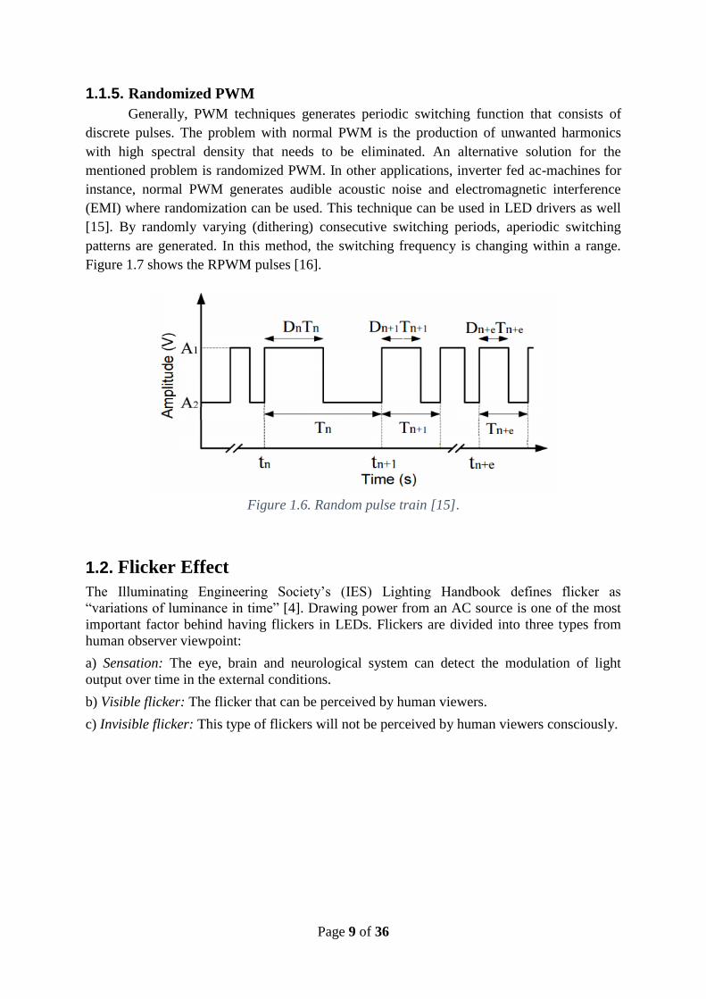
1.1.5. Randomized PWM
Generally, PWM techniques generates periodic switching function that consists of
discrete pulses. The problem with normal PWM is the production of unwanted harmonics
with high spectral density that needs to be eliminated. An alternative solution for the
mentioned problem is randomized PWM. In other applications, inverter fed ac-machines for
instance, normal PWM generates audible acoustic noise and electromagnetic interference
(EMI) where randomization can be used. This technique can be used in LED drivers as well
[15]. By randomly varying (dithering) consecutive switching periods, aperiodic switching
patterns are generated. In this method, the switching frequency is changing within a range.
Figure 1.7 shows the RPWM pulses [16].
Figure 1.6. Random pulse train [15].
1.2. Flicker Effect
The Illuminating Engineering Society’s (IES) Lighting Handbook defines flicker as
“variations of luminance in time” [4]. Drawing power from an AC source is one of the most
important factor behind having flickers in LEDs. Flickers are divided into three types from
human observer viewpoint:
a) Sensation: The eye, brain and neurological system can detect the modulation of light
output over time in the external conditions.
b) Visible flicker: The flicker that can be perceived by human viewers.
c) Invisible flicker: This type of flickers will not be perceived by human viewers consciously.

Page 10 of 36
Figure 1.7. LED Flicker
Both visible and invisible flicker have several effects on the human health. The health effect
of the flicker can be divided into two groups. Immediate result such as epileptic seizures and
long term result such as headaches and visual performance. The first will happen with the
visible flicker usually within 3 to 70 Hz switching frequency and the latter when the flicker is
not perceivable. [4]
1.3. Multicolour LED lighting
1.3.1. Issues
There are two main challenges in dimming of multicolour LEDs. The first one is the
colour shift. Changes in the forward current of LEDs affects the junction temperature of the
device, which can influence the spectral power distribution. The second one is the variation
of the light intensity while light output colour is changed.
1.3.2. Colour Control
This section presents the centre of gravity method used to produce various colours using red,
blue and green LEDs. As shown in Figure 1.8, to obtain the x and y coordinates of a target
colour (e.g. white colour), the equations representing two lines (i.e. red-blue and green-
target) should be obtained [6]. For deriving the equation for the red-blue line, the colour (red,
green and blue) coordinates of the RGB LED component are needed. For this purpose, the
LED datasheet can be used or alternatively, they can be measured. Afterwards, a linear
equation should be solved using x-y coordinates of the red and blue colours to find the slope
of the line (m) and derive equation (1).
y=mx+C (1)
Second line (i.e. green-target) equation is obtained in a similar way as the previous one using
the green and the target colour x-y coordinates. The interception point of the two lines (x3,
y3) is used to derive the RGB ratios using equation (2) where (x1, y1) is the x-y coordinate
of red (x2, y2) and (x3, y3) are the blue and intercept point coordinates, respectively.
r_RB = - (y2/y1) × (y1-y3) / (y2-y3) (2)
Firstly, the red-blue ratio (r_RB) is achieved by putting the mentioned coordinates inside

Page 11 of 36
equation (2) and then the ratio of green-intercept (r_GP) point is obtained using target colour
coordinates as (x1, y1), green colour coordinates as (x2, y2) and intercept point coordinates
as (x3, y3).
The next step is to calculate RGB colour ratios individually and the duty cycles of the red,
green and blue LEDs using the equations (3) to (5) and (6) to (8), respectively.
ratio_R = r_RB/(r_RB+1) (3)
ratio_G = r_GP (4)
ratio_B = 1/(r_RB+1) (5)
red duty cycle = blue_max / red_max * ratio_R / total_ratio (6)
green duty cycle = blue_max / green_max * ratio_G / total_ratio (7)
blue duty cycle = blue_max / blue_max * ratio_B / total_ratio (8)
Figure 1.8. Representation of red, blue, green and target colour (e.g. white) in CIE
chromaticity diagram [6]
where,
- blue_max is the maximum brightness of the blue LED in lumens.
- red_max is the maximum brightness of the red LED in lumens.
- green_max is the maximum brightness of the green LED in lumens.
The previous values were measured in the laboratory. Blue colour LED has the lowest
brightness amongst all and that is why its light intensity is considered for calculating the duty
cycles.

Page 12 of 36
2. Objective
The main purpose of this project was to create two different LED drivers. One of the drivers
was focused on the PWM based LED dimming and the other on multicolour LED intensity
control. The LED drivers were modified from existing Helvar LED drivers. In the PWM
driver, the goal was to drive the LED with a randomized switching frequency to minimize the
flicker effect visible on HD cameras when used in LED lighting environment.
The second goal of the project was to design a multicolour LED driver which works in a way
that the light intensity is controlled, irrespective of emitted colour (additive) output and
colour was controlled irrespective of change in intensity (dimming). The LED driver was
modified from three Helvar LED drivers with an external microcontroller controlling the duty
cycle of each of the three colours (red, green and blue).
3. Project plan
Project comprises two phases. During the first phase, literature study was done on the flicker
effect, lighting, dimming and various techniques of pulse width modulation (PWM). By
finding the main issue, possible solutions were discussed. The next step was to finalize the
idea, to extend and build a proper practical plan for it. It was decided that, the best way to
start the project is to experiment with laboratory equipment to meet the requirement of the
project. Afterwards, HD cameras and the flicker effect on the human eyes were evaluated.
Since this project was the collaboration between Aalto university and Helvar Oy, specific
driver made by the company was supposed to be used.
However, experiments were done on a new microcontroller which replaced the
existing microcontroller in the driver. An appropriate microcontroller board was selected.
Constant frequency PWM was programmed and implemented to figure out the problem.
Next, randomized frequency PWM was programmed and implemented to see the results and
making comparisons. The results validation and documentation was the next step. Other
random PWM technique such as random position PWM and hybrid random PWM was
implemented and tested with the normal PWM. But these methods, doesn’t help i.e. the
flicker was clearly visible. Parallel with the PWM testing the business aspects and market
study of the project were completed and presented.
In the second phase, since the aim was to formulate a method for creating various
colours using RGB LEDs with controlled intensity colour mixing and colour space
transformations were studied. In this part, a driver was designed using a controller to drive
RGB LEDs through three Helvar driver circuits. Several algorithms/colour space
transformations were studied to control the RGB LEDs for this purpose and the most
practical one was selected. Finally, to assess the performance of the driver, laboratory
measurements were carried out.

Page 13 of 36
4. Hardware setup This project used Helvar LL1-CV-DA LED drivers (Figure 4.2.) with DALI interface
originally. These LED Drivers are modified by removing their own microcontroller and
connecting DALI screw terminals to original microcontroller PWM output and ground. Thus,
it was convenient to do experiments with different microcontrollers. LL1-CV-DA LED
drivers work in 12-24V DC voltage range. In this project, only 24V DC LED modules were
used.
4.1. Flicker-free LED lighting The flicker-free LED demo driver consists of one modified LL1-CV-DA LED driver, 24V
DC power supply, LED, ATmega328p microcontroller unit and HD video camera. There’s
also one potentiometer and two switches for simple interface. Microcontroller firmware
update and development is done using USB cable and Arduino IDE (Integrated Development
Environment).
Figure 4.1. Flicker-free LED lighting demonstration prototype
Figure 4.2. Flicker-free LED lighting demonstration prototype from inside

Page 14 of 36
4.1.1. Controller selection
Atmel ATmega 328p microcontroller is used to implement flicker-free LED lighting.
Because of readily available and wide variety Arduino development boards, implementation
of randomized PWM prototype is built using popular Arduino UNO development board.
Table 4.1. ATmega328p pins and descriptions [17]
ATmega328p/
Arduino pin
Description Connected to
5V 5 VDC Potentiometer third terminal
RESET Microcontroller reset Reset switch
PC0 / A0 ADC input 0, port C 0 Potentiometer second terminal (wiper)
PD3 / IO3 PWM output, port D 3 LED Driver
PD4 / IO4 Digital input, port D 4 RPWM/PWM Switch
GND Ground LED Driver ground. Potentiometer first
terminal, reset switch, RPWM/PWM
Switch
True C programming had to be used to switch microcontroller's output state since it enables
greatly faster control of I/O pins than using Arduino's simplified functions (DigitalWrite and
AnalogWrite).
The ATmega 328p microcontroller system clock operates only at 16 MHz which limits the
possibilities of dimming resolution, maximum frequency and real-time controlling.
Additionally, it only allows to include a very outdated interface consisting of momentary
push button (Reset), simple on-off switch (RPWM/PWM Switch) and potentiometer to
control duty cycle. The interface is not interfering with randomized PWM algorithm since
potentiometer value and switch state are only read at the start-up of the microcontroller. Reset
switch is thus needed to apply parameters. Table 4.1 and figure 4.3 shows microcontroller
pins needed in Flicker-free demo.

Page 15 of 36
Figure 4.3. Arduino UNO and flicker-free LED lighting wiring

Page 16 of 36
4.1.2. HD Video camera
All flicker-related measurements are done using Panasonic HDC-SD700 Full HD video
camera (Table 4.2. and figure 4.4.).
Table 4.2. Full HD video camera technical information [18]
Manufacturer and model Panasonic HDC-SD700
Sensor type and
properties
1/4.1” 3MOS image sensor
Total pixels: 3050 K x 3
Effective pixels: Motion picture: 2530 K x 3 (16:9)
Lens properties Auto Iris, F1.5 to F2.8
Focal length: 3.45 mm to 41.4 mm
Resolution 1920x1080/50p
1920x1080/50i
Framerate 50p (progressive) or 50i (interlaced)
Shutter speed 1/50 to 1/8000
Release year 2010
Figure 4.4. Panasonic HDC-SD700 Full HD video camera.

Page 17 of 36
4.2. Colour control The colour control demo consist of three modified LL1-CV-DA LED drivers, 24 VDC power
supply, 24V DC RGB LED and STM32F103 microcontroller unit. There’s also few
potentiometers for simple interface. Microcontroller firmware update and development is
done using ST-LINK/V2 USB programmer and Keil µVision 5 IDE.
Figure 4.5. Colour control demonstration prototype setup
Figure 4.6. Colour control demonstration prototype: slider potentiometer control,
microcontroller board and LED drivers.

Page 18 of 36
Figure 4.7. Slide potentiometer user interface with fine adjustment sliders (Fine adjustment
and coarse adjustment potentiometer wipers were connected to 10 kΩ resistor)
4.2.1. Controller selection
STM32F103 microcontroller from STMicroelectronics is used to implement colour control
LED lighting.
Table 4.3. STM32F103 pins and descriptions [19]
STM32F
103 pin
Description Connected to
3V3 3.3 VDC Potentiometers third terminal
PA0 ADC input 0, port A 0 Potentiometer #1 second terminal (wiper)
PA1 ADC input 1, port A 1 Potentiometer #2 second terminal (wiper)
PA2 ADC input 2, port A 2 Potentiometer #3 second terminal (wiper)
PB11 PWM output, port B 11 Blue LED Driver
PB13 PWM output, port B 13 Red LED Driver
PB15 PWM output, port B 15 Green LED Driver
GND Ground LED Drivers ground. Potentiometer first terminal
The interface consists of three potentiometers to control duty cycle, chromaticity x- and y-
coordinates. Due to STM32F103 microcontroller fast 72 MHz system clock, it was possible
to achieve real-time control without affecting the functionality. When compared to
ATmega328p (16MHz system clock) it makes possible to change parameters real-time
without causing visible flicker, multithreading makes easier to implement multicolour control
and possible to use more complex and accurate algorithm to create colours. Table 4.3 and
figure 4.8 shows microcontroller pins needed in colour control part of this project.

Page 19 of 36
Figure 4.8. STM32F103 development board

Page 20 of 36
5. Results
5.1. Normal PWM (Constant Frequency) Constant-frequency PWM was used to drive a white LED strip. The switching frequency,
(fPWM) used was 1000 Hz and the duty cycle, D is 30%. The result is shown in the Figure 5.1.
Figure 5.1. Light output with PWM Dimming (D=30%, fPWM=1000 Hz)
Since the issue is the implementation of PWM for duty cycles from 0.1 to 30 percent, further
experiments were done with lower duty cycles as well and the results are shown in figures 5.2
and 5.3.
Figure 5.2. Light output with PWM Dimming (D=10%, fPWM=1000 Hz)

Page 21 of 36
Figure 5.3. Light output with PWM Dimming (D=0.1%, fPWM=1000 Hz)
The flickering effect can be seen explicitly on videos. Therefore, pictures from the HD video
camera recordings were used to visually analyse the resulted flicker. It can be clearly seen in
the pictures presented that using the constant frequency PWM creates image flicker. In other
words, the flickering effect can be seen due to the gaps in the PWM current waveform that
are visible in shape of dark-moving strips.
5.2. Random Frequency PWM
5.2.1. Randomized PWM with Frequency up to 1kHz
The randomized PWM (RPWM) frequency was used to drive the white LED strip. In
this case, the switching frequency is varying within a limit that is 800-1000 Hz with a
constant duty cycle of 50%. The result is shown in the Figure 5.4.
Figure 5.4. Light output with RPWM Dimming (D=50%, 800<fPWM<1000 Hz)
More experiments were done with lower duty cycles to compare the results with constant
frequency PWM and results are shown in figures 5.5 to 5.7.

Page 22 of 36
Figure 5.5. Light output with RPWM Dimming (D=30%, 800<fPWM<1000 Hz)
Figure 5.6. Light output with RPWM Dimming (D=10%, 800<fPWM<1000 Hz)
Figure 5.7. Light output with RPWM Dimming (D=0.1%, 800<fPWM<1000 Hz)

Page 23 of 36
It can be clearly seen that the RPWM contributed towards reducing the flicker and the effect
was significant. However, there is still some problems and even visible flicker according to
the captured video. In fact, randomized PWM generates an asymmetric train of pulses which
produces random and spread dark-moving strips compared to the constant dark-moving strips
of the so-called flicker effect generated by normal PWM. Consequently, the flicker effect is
less visible. Besides, using faster shutter speeds, 1/500 or 1/750 make it easier to see the
phenomenon.
5.2.2. Randomized PWM with Increased Frequency
As mentioned in the previous part, RPWM does not remove the flicker completely. As a
result, another improvement is to increase the switching frequency. In this case, the
switching frequency is varying within a limit that is 4300-5000 Hz and the duty cycle is 30%.
The results is shown in the Figure 5.8.
Figure 5.8. Light output with high frequency RPWM Dimming
(D=30%, 4300<fPWM<5000 Hz)
Dimming the output is done by reducing the duty cycle and the results are documented in
figures 5.9 to 5.11.
Figure 5.9. Light output with high frequency RPWM Dimming
(D=10%, 4300<fPWM<5000 Hz)

Page 24 of 36
Figure 5.10. Light output with high frequency RPWM Dimming
(D=1%, 4300<fPWM<5000 Hz)
Figure 5.11. Light output with high frequency RPWM Dimming
(D=0.1%, 4300<fPWM<5000 Hz)
Obviously, by increasing the frequency the flicker is significantly decreased. In addition,
there is no visible flicker even with the lowest value of duty cycle that is used which is 0.1%
when the HD camera is used with 1/125 shutter speed. It means the asymmetric pulses
generated by RPWM with higher frequencies lead to less visible compared to lower
frequencies of RPWM. However, using faster shutter speeds, 1/750 for instance, the flicker is
more likely to be visible on the image.
5.3. Multicolour LED lighting control
5.3.1. Colour control
To assess the performance of the control algorithm used, the x-y chromaticity coordinates of
different colours were measured in the laboratory using a high-resolution spectrophotometer.
The measurements focused on the colour coordinate differences while changing the LED

Page 25 of 36
brightness. The different colours used for the measurements are shown in the Figures 5.14
and 5.15. Table 5.1 presents the x-y coordinates of five different colours measured in
laboratory at two different brightness levels.
Table 5.1. Colour control measurement results
Colour X Y Brightness
Blue 0.1416 0.0491 1
Blue 0.1435 0.0505 0.5
Green 0.1497 0.6768 1
Green 0.1589 0.6556 0.5
White 0.3013 0.3851 1
White 0.3045 0.3735 0.5
Yellow 0.4437 0.4778 1
Yellow 0.4445 0.4745 0.5
Magenta 0.5510 0.2393 1
Magenta 0.5531 0.2404 0.5
The difference between the chromaticity coordinates in the two measurements can be
calculated with equations 9 and 10. In equations 9 and 10, 𝑋1.0is the full-brightness x-
coordinate and 𝑋0.5 is the half brightness x-coordinate. The same applies for the subscript in
y-coordinate.
𝛥𝑋(%) = ( 𝑋1.0
𝑋0.5 − 1) ⋅ 100% (9)
𝛥𝑌(%) = ( 𝑌1.0
𝑌0.5 − 1) ⋅ 100% (10)
The results of these coordinate errors are shown in Table 5.2. The largest coordinate error is
in the green colour. The blue and white colours also have some error but yellow and magenta
colours have very little colour shift. The differences of table 5.2 are further illustrated as a bar
graph in figure 5.12.

Page 26 of 36
Table 5.2. Chromaticity coordinate errors when brightness is varied
between 1 and 0.5.
Colour X coordinate error (%) Y coordinate error (%)
Blue 1.34% 2.85%
Green 6.15% -3.13%
White 1.06% -3.01%
Yellow 0.18% -0.69%
Magenta 0.38% 0.46%
Figure 5.12. Chromaticity coordinate errors when brightness is varied between
values 1 and 0.5
All ten measuring points are plotted in CIE colour space chromaticity diagram in figure 5.13.
As can be seen from the figure 5.13, there is a slight colour shift in the generated green colour
with different brightness levels but the x-y coordinates of the other colours are kept
approximately the same while the brightness is reduced to half of the full value.

Page 27 of 36
Figure 5.13. Location of the different colours measured at half and full brightness in
CIE chromaticity diagram.
5.3.2. Intensity Control
The objective of intensity control is to maintain the brightness of a RGB LED irrespective of
the any colour. The duty cycles of the red, green and blue LEDs are controlled individually to
keep the brightness approximately constant when the colour is changed. The results of the
implemented intensity controller are shown in table 5.3. In the table, target x-y is the value of
chromaticity coordinate given as an input to the controller which calculates the duty cycles
for red, green and blue to obtain this colour. The actual x-y coordinates are the colour
coordinate values measured from the controlled light output. The brightness is normalized
with respect to blue.
Figure 5.14. Multicolour LED- Blue colour with higher intensity

Page 28 of 36
As seen from the results, the brightness stays constant except with blue colour. The figure
5.15, represents the light output of different colours with same intensity. The difference in the
brightness of the other colours cannot be easily distinguished with bare eye. The figure 5.14,
represents the blue colour with higher intensity. The error in the brightness of the blue colour
is most likely due to a programming error
Figure 5.15. Multicolour LED- Different colours with same intensity
The target and actual x and y coordinates of five different colours are shown in figures 5.16
& 5.17. The x-coordinate are shown in figure 5.16 and y-coordinate in figure 5.17. As can be
seen in figure 5.16, there difference in the actual x-coordinate of the colours is very small,
except in magenta. However, in actual y-coordinate the difference is more in green, white and
yellow colours. Y-coordinate of blue and magenta are very accurate.
Table 5.3. Colour intensity control measurement results
Colour Target x-y
coordinates
Actual x-y
coordinates
Normalized
brightness
Blue 0.1416-0.0491 0.1414-0.0492 1
Green 0.1497-0.6768 0.1447-0.6229 0.08218
White 0.3013-0.3851 0.3045-0.3695 0.08804
Yellow 0.4445-0.4745 0.4383-0.4507 0.08756
Magenta 0.5510-0.2393 0.539-0.2440 0.09103

Page 29 of 36
Figure 5.16. Target and Actual x coordinate
Figure 5.17. Target and Actual y coordinate
The differences between x and y coordinates are also shown as percentages in figure 5.18.
The percentages are calculated using equations 9 and 10. In figure 5.18 can be seen that the
difference in the y-coordinate of green colour is large but otherwise the x-y coordinates of the
target colour and actual colour are very close.

Page 30 of 36
Figure 5.18. difference between target and actual x-y coordinates
In conclusion, according to table 5.3 and figures 5.16 to 5.18, the actual and target x-y
coordinates that are produced by the controller and measured in the output are nearly zero. In
addition, the brightness level is approximately kept constant while changing the colours.
However, luminous flux of the blue colour was considerably higher than the other colours.
This is likely due to a programming error but this couldn’t be confirmed. Overall green
colour had the largest errors and other colours had some small errors.

Page 31 of 36
6. Reflection of the Project
6.1. Reaching objective
The main goal of this project was to determine whether driving the LED with
randomized frequency PWM is a solution for the flicker effect visible in HD cameras. The
flicker-free LED lighting or at least reduced flicker LED lighting was fully achieved. The
second goal was to control, colour shift on dimming and light intensity while changing
colours (of RGB LEDs).
In short, the objectives of the project were partially achieved. The flicker in the LED
lighting was reduced using the randomized PWM method with increased switching frequency
instead of normal PWM. The second objective of controlling colour and intensity of RGB
LEDs was achieved to a certain extent with the centre of gravity method using CIE chart.
6.2. Timetable
Although there were some points in which the project was lagging the timetable, especially in
some phases that needed experiments and tests, the time schedule was followed properly and
project requirements were reasonably met by the group members. Appendix I shows the
project timetable.
6.3. Risk analysis
The main aim of the project is to build a flicker free LED driver. However, the randomized
PWM is not the optimal solution for flicker free. This wasn’t considered as a risk in planning
phase. But we managed to remove the flicker by driving the LEDs at higher switching
frequency. As mentioned in our project plan, we realized ‘underestimated work load’ in the
second phase of the project. The multicolour part workload was more than what we have
expected. So, we used more man-hours to finish the multicolour part.
6.4. Project Meetings
The group had regular official meetings every week, usually on Wednesdays about the
situation of the project, future phase of the project among other issues. The group had some
punctual unofficial meetings mostly to carry out laboratory measurements. The cell phone
had been used between meetings. A WhatsApp group was used to specify the place and time
for the meetings. The results of the laboratory measurements, literatures for studying and
time registration file were shared using Google Drive. The project manager had prepared
agenda for every meeting and sent to the group members three days before the official
meetings by E-mail. In every meeting, one of the group members was selected as a chairman
and one as a secretary. The secretary was supposed to write the minutes of the previous
official meetings where all issues discussed must be mentioned and sent to the project
manager. The project manager archived the minutes and agendas of the meetings in Google
Drive.
6.5. Quality management
In every project work, the activities and phases are pre-planned and time schedule is prepared
in advance. Quality of the different phases is checked by the project manager and the
academic instructor along with the industry advisor. Since, the project is a practical one and
related to the industry, some phases of the project such as the RPWM solution and multi-
colour control was double checked and some modifications were added by the group

Page 32 of 36
members. The experiments were done by different microcontrollers to achieve comparable
results. In some parts the LED strips were changed and more qualified LED freights were
used to reduce the error. Multi-colour control was the most challenging part of the project and
a great amount of effort was dedicated to the part which makes RGB LED driver prototype a
unique and pioneer product. On the other hand, the inevitable challenge in much of the
project is time management which is extremely essential especially for short time projects.
Consequently, to meet the deadline, group members were supposed to work with a faster pace
at some intervals.
6.6. Future work There are several aspects that can be considered for future studies. The algorithm used in
multicolour LED driver linearizes the brightness-duty cycle curves of the LEDs i.e. duty
cycle is directly proportional to brightness. This linearization causes some errors in the output
colours and brightness of the LED driver. One solution to this problem could be measuring
the brightness of each colour between 0 and 100% duty cycle and to create a curve from the
it. The appropriate duty cycle can be selected from the curves. Another alternative could be
using look-up tables for selection of duty cycle at (e.g. 1% steps).
Other possibility of attaining a better control of colour and intensity in RGB LEDs is to have
closed loop system using LED junction temperature as feedback signal. The disadvantage of
this approach will be the increase in hardware complexity.
In the flicker free part, RPWM uses only flat probability distribution of frequency.
Different kinds of probability distributions (e.g. Gaussian). This could be tested to check if it
makes a significant difference in the flicker.

Page 33 of 36
7. Discussion and Conclusions
The purpose of the first phase of this study was to evaluate PWM-dimming impact on video,
using HD cameras and to see if the effect was corrected with randomized PWM-frequency.
The PWM generates undesirable flicker that can be seen by the camera or even under some
circumstances with the naked eye. The randomized PWM, helps with reducing the flicker,
however, this driving and dimming technique is not the solution for flicker-free illumination.
Therefore, digital PWM and RPWM is implemented by means of microcontrollers. In
addition, the RPWM with the increased frequency is a better solution for diminishing the
flicker effect seen through the HD cameras especially with lower shutter speeds, for instance
1/100 or 1/125. The appropriate frequency for the RPWM tested by various tests is 4300 to
5000 Hz that means increasing the frequency contributes towards minimizing the flicker
effect.
The second phase of the project was to produce a RGB led drivers for generating different
colours along with changing the light intensity separately. The problem with multi-colour
control is the colour chromaticity shift happens while dimming or the intensity changes in the
output light while changing the colour. A mathematical algorithm was derived to create
various colours with the possibility of changing the brightness. Since the control algorithm
used linear estimation of red, green and blue duty cycles, the target colour obtained by the
controller was not exactly the wanted colour. Therefore, there were some differences between
the target colour coordinates and the actual colour provided by the controller. The other
problem seen in the performance of the controller is the blue colour which seemingly has a
brighter output in some cases.
In future work, junction temperature based closed loop control can be built to achieve
constant output luminous flux for each colour, reducing the colour shift due to varying
junction temperature [20].
8. List of Appendixes
● Project plan-Time table

Page 34 of 36
9. References
[1] Zion market research, LED Lighting Market for Residential, Architectural and
Outdoor Applications: “Global Industry Perspective, Comprehensive Analysis and
Forecast, 2016 - 2022”. Accessed 24.1.2017
https://www.zionmarketresearch.com/news/led-lighting-market
[2] Understand compatibility, performance, and dimming issues in LED lighting, LED
magazine, Accessed10.6.2013
http://www.ledsmagazine.com/articles/iif/print/volume-2/issue-6/features/understand-
compatibility-performance-and-dimming-issues-in-led-lighting-magazine.html
[3] Lech Grodzki, Bialystok University of Technology, “The Comparison of the Pulse
and Constant-current LED Driving”, PRZEGLĄD ELEKTROTECHNICZNY, ISSN
0033-2097, R. 89 NR 11/2013
[4] A.Wilkins, J. Veitch, and B. Lehman, “LED lighting flicker and potential health
concerns:IEEE standard PAR1789 update,” in Proc. IEEE Energy Convers. Congr.
Expo., 2010, pp. 171–178.
[5] Osram, Technical application guide, OPTOTRONIC LED drivers for indoor
application, 2015. Accessed 21.5.2017
http://www.osram.it/media/resource/HIRES/637695/technical-application-guide-
optotronic-led-drivers-for-indoor-applications--gb.pdf.
[6] Lee Boon Hooi, Understand RGB LED mixing ratios to realize optimal colour in
signs and displays, LED magazine, Accessed 14.5.2013
http://www.ledsmagazine.com/articles/print/volume-10/issue-6/features/understand-
rgb-led-mixing-ratios-to-realize-optimal-colour-in-signs-and-displays-magazine.html
[7] “What are the different methods used for dimming? “Accessed 24.5.2017
https: //www.dmlights.com/help/lighting/different-methods-dimming/
[8] Peter Di Maso, Texas Instruments,” Efficient dimming for LED lighting”, Accessed
28.2.2012
http://www.electronicproducts.com/Power_Products/Power_Management/Efficient_d
imming_for_LED_lighting.aspx
[9] Lutron, Dimming LEDs via PWM and CCR, Application Note, 2016, Accessed
21.5.2017 http://www.lutron.com/TechnicalDocumentLibrary/048360.pdf.
[10] Steven Keeping, “LED Colour Shift Under PWM Dimming”, Accessed 11.04.2014
https://www.digikey.com/en/articles/techzone/2014/feb/led-colour-shift-under-pwm-
dimming
[11] Texas Instruments, Analog Dimming with the TPS61181, Application Report, 2011.
Accessed 21.5.2017 http://www.ti.com/lit/an/slva493/slva493.pdf.
[12] Alice Liao, “LEDs: A Deep Dive in Dimming”, Arch lighting, 2014, Accessed
21.5.2017 http://www.archlighting.com/technology/leds-a-deep-dive-in dimming_o.
[13] Timothy Hirzel. Arduino PWM tutorial, Accessed 30.5.2017
https://www.arduino.cc/en/Tutorial/PWM.

Page 35 of 36
[14] Helvar, Enhanced hybrid dimming technologies for better light quality. Accessed
30.5.2017 https://www.helvar.com/en/solutions/solutions-for-luminaires/hybrid-
dimming/.
[15] Michael M. Bech, Analysis of Random Pulse-Width Modulation for Power Electronic
Converters.
[16] Andrzej M. Trzynadlowski, Introduction to Modern Power Electronics, 3rd edition,
Hoboken, New Jersey, John Wiley & Sons, Inc.,2016, ISBN 978-1-119-00321-2.
[17] Arduino, Arduino UNO schematics, Accessed 24.5.2017
https://www.arduino.cc/en/uploads/Main/Arduino_Uno_Rev3-schematic.pdf
[18] Panasonic, Panasonic HDC-SD700 manual, Accessed 24.5.2017
http://www.panasonic.com/content/dam/Panasonic/support_manual/Camcorder_Digit
al/English/vqt2m96.pdf.
[19] STMicroelectronics, STM32F103 Datasheet, Accessed 24.5.2017
http://pe.org.pl/articles/2013/11/68.pdf.
[20] R. Cordeiro, A. Cardoso, R. Duarte, D. Soares, G. Pereira, W. Vizzotto, V. Bender
and T. Marchesan, "Indirect control of luminous flux and chromatic shift
methodology applied to RGB LEDs", 2014 11th IEEE/IAS International Conference
on Industry Applications, 2014.

Page 36 of 36
10. Appendix I