final safety analysis report chapter 10 steam and … · turbine protection system overspeed...
TRANSCRIPT

CCNPP Unit 3 © 2007-2014 UniStar Nuclear Services, LLC. All rights reserved. LBDCR Rev 9FCOPYRIGHT PROTECTED
FINAL SAFETY ANALYSIS REPORT
CHAPTER 10
STEAM AND POWER CONVERSION SYSTEM
CALVERTCC3-14-0013GN-14-0044CC3-14-0045CC3-14-0083
Revision 10 - Interim

FSAR: Chapter 10.0 Steam and Power Conversion System
CCNPP Unit 3 10.0-1 LBDCR Rev 9F© 2007-2014 UniStar Nuclear Services, LLC. All rights reserved.
COPYRIGHT PROTECTED
10.0 STEAM AND POWER CONVERSION SYSTEM
This chapter of the U.S. EPR Final Safety Analysis Report (FSAR) is incorporated by reference with supplements as identified in the following sections.
Revision 10 - Interim

FSAR: Chapter 10.0 Summary Description
CCNPP Unit 3 10.1-1 LBDCR Rev 9F© 2007-2014 UniStar Nuclear Services, LLC. All rights reserved.
COPYRIGHT PROTECTED
10.1 SUMMARY DESCRIPTION
This section of the U.S. EPR FSAR is incorporated by reference.
Revision 10 - Interim

FSAR: Chapter 10.0 Turbine-Generator
CCNPP Unit 3 10.2-1 LBDCR Rev 9F© 2007-2014 UniStar Nuclear Services, LLC. All rights reserved.
COPYRIGHT PROTECTED
10.2 TURBINE-GENERATOR
This section of the U.S. EPR FSAR is incorporated by reference with the following supplements.
10.2.1 Design Bases
No departures or supplements.
10.2.2 General Description
This section of the U.S EPR FSAR is incorporated by reference with the following supplements.
10.2.2.1 Component Description
No departure or supplements.
10.2.2.2 TG Foundation
No departure or supplements.
10.2.2.3 Cycle Description
No departure or supplements.
10.2.2.4 Excitation System
No departure or supplements.
10.2.2.5 TG Control System
No departure or supplements.
10.2.2.6 Speed Control
No departure or supplements.
10.2.2.7 Load Control
No departure or supplements.
10.2.2.8 Valve Control
No departure or supplements.
10.2.2.9 Overspeed Control
The U. S. EPR FSAR includes the following COL Item in Section 10.2.2.9:
A COL applicant that references the U.S. EPR design certification will provide a reliability evaluation of the overspeed protection system, which includes the inspection, testing, and maintenance requirements needed to demonstrate reliable performance of the system.
GN-10-0191
GN-10-0191
GN-10-0191
GN-10-0191
GN-10-0191
GN-10-0191
GN-11-0133
GN-10-0191
GN-10-0191
GN-10-0191
GN-10-0191
GN-12-0192
GN-12-0192
Revision 10 - Interim

FSAR: Chapter 10.0 Turbine-Generator
CCNPP Unit 3 10.2-2 LBDCR Rev 9F© 2007-2014 UniStar Nuclear Services, LLC. All rights reserved.
COPYRIGHT PROTECTED
This COL Item is addressed as follows:
The overspeed protection system evaluation for the turbine generator, in terms of architecture and probability of failure on demand, is included in Alstom Document 75RC10001, Steam Turbine Protection System Overspeed Reliability Evaluation (Alstom, 2010). Based on the inspections and tests of the overspeed protection system defined in Chapter 4.2 of Alstom Report TSDMF 07-018 D (Alstom, 2007), the overall failure rate of the overspeed protection system is approximately 1.14E-9. In addition, plant procedures will control the inspection, testing and maintenance requirements for the turbine, including the requirements for the turbine overspeed protection system.
10.2.2.10 Turbine Supervisory Instrumentation
No departure or supplements.
10.2.2.11 Other Protection System
No departure or supplements.
10.2.2.12 Turbine Inservice Inspection and Testing
The U. S. EPR FSAR includes the following COL Item in Section 10.2.2.12:
A COL applicant that references the U.S. EPR design certification will provide the site-specific inservice inspection program, inspection intervals, and exercise intervals consistent with the turbine manufacturer’s recommendations for the main steam stop and control valves, the reheat stop and intercept valves, and the extraction non-return valves.
This COL Item is addressed as follows:
The inservice inspection program will include the inspection intervals and exercise intervals consistent with the turbine manufacturer’s recommendations for the main steam stop and control valves, the reheat stop and intercept valves, and the extraction nonreturn valves. Table 13.4-1 provides the inservice inspection implementation milestone.
10.2.3 Turbine Rotor Integrity
No departures or supplements.
10.2.3.1 Materials Selection
The U.S. EPR FSAR includes the following COL Item in Section 10.2.3.1:
A COL applicant that references the U.S. EPR design certification will provide applicable material properties of the site-specific turbine rotor, including the method of calculating the fracture toughness properties.
This COL Item is addressed as follows:
{Calvert Cliffs 3 Nuclear Project, LLC and UniStar Nuclear Operating Services, LLC} shall submit to the NRC the applicable material properties of the site-specific turbine rotor, including the method of calculating the fracture toughness properties.
GN-12-0192
GN-12-0192
GN-10-0191
GN-10-0191
GN-10-0191
GN-12-0192
GN-12-0192
GN-12-0192
GN-12-0192
GN-10-0191
GN-10-0191
GN-10-0191
GN-10-0191
GN-10-0191
Revision 10 - Interim

FSAR: Chapter 10.0 Turbine-Generator
CCNPP Unit 3 10.2-3 LBDCR Rev 9F© 2007-2014 UniStar Nuclear Services, LLC. All rights reserved.
COPYRIGHT PROTECTED
10.2.3.2 Fracture Toughness
The U.S. EPR FSAR includes the following COL Item in Section 10.2.3.2:
A COL applicant that references the U.S. EPR design certification will provide applicable site-specific turbine disk rotor specimen test data, load-displacement data from the compact tension specimens and fracture toughness properties.
This COL Item is addressed as follows:
{Calvert Cliffs 3 Nuclear Project, LLC and UniStar Nuclear Operating Services, LLC} shall submit to the NRC the applicable site-specific turbine disk rotor specimen test data, load-displacement data from the compact tension specimens and the fracture toughness properties to demonstrate that the associated information and data presented in the U.S. EPR FSAR is bounding.
10.2.3.3 High Temperature Properties
No departures or supplements.
10.2.3.4 Turbine Rotor Design
No departures or supplements.
10.2.3.5 Turbine Rotor Preservice Inspections and Testing
No departures or supplements.
10.2.3.6 Turbine Rotor Inservice Inspection Program Plan
The U.S. EPR FSAR includes the following COL Item in Section 10.2.3.6:
A COL applicant that references the U.S. EPR design certification will provide the site-specific turbine rotor inservice inspection program and inspection interval consistent with the manufacturer’s turbine missile analysis.
This COL Item is addressed as follows:
The turbine manufacturer recommends major rotor inspection intervals of 10 years, during major overhauls. The inspections are performed during refueling outages on an interval consistent with the inservice inspection schedules in ASME Section XI so that a total inspection has been completed at least once within a 10 year time period. The turbine rotor manufacturer has provided, within the Turbine Missile Analysis, specific analysis demonstrating that any crack assumed to start at t=0 (the beginning of the period between two inservice inspections), whether initiated on an exterior face or the internal faces of the internal and external disc fingers, will propagate to the surface of the rotor and will not reach critical size before the next inservice inspection. Such defects shall be detected via visual examination or selected surface examinations of the turbine rotor during the inservice inspection. The Turbine Rotor Inservice Inspection Program Plan will include a requirement to perform a visual inspection or selected surface examinations of the turbine rotor during the inservice inspection. And, in the event a surface defect is detected, to either perform an ultrasonic examination of the turbine rotor welds or have the turbine manufacturer provide an analysis which demonstrates that defects in the root of the rotor welds will not grow to critical size for the life of the rotor.
GN-10-0191
GN-12-0153
GN-10-0191
GN-12-0153
GN-10-0191
GN-14-0044
Revision 10 - Interim

FSAR: Chapter 10.0 Turbine-Generator
CCNPP Unit 3 10.2-4 LBDCR Rev 9F© 2007-2014 UniStar Nuclear Services, LLC. All rights reserved.
COPYRIGHT PROTECTED
The U.S. EPR FSAR includes the following COL Item in Section 10.2.3.6:
A COL applicant that references the U.S. EPR design certification will include ultrasonic examination of the turbine rotor welds or provide an analysis which demonstrates that defects in the root of the rotor welds will not grow to critical size for the life of the rotor.
This COL Item is addressed as follows:
The turbine manufacturer shall perform a preservice 100% volumetric examination of all turbine welds during manufacturing to verify the turbine rotor welds are free from any unacceptable defects. An analysis has been provided by the turbine manufacturer, Alstom document TNUD-EI 10-011 (Alstom, 2010a), to demonstrate that defects of an acceptable size will not grow to critical size for the life of the turbine rotor, even if they propagate under cyclic loading.
10.2.4 Safety Evaluation
No departures or supplements.
10.2.5 References
Alstom, 2007. Alstom Report TSDMF 07-018 D, Unistar Project Turbine Missile Analysis, dated May 30, 2007.
Alstom, 2010. Alstom Document 75RC10001, Steam Turbine Protection System Overspeed Reliability Evaluation, dated March 2, 2010.
Alstom, 2010a. Alstom Document TNUD-EI 10-011, UniStar Project Turbine Missile Analysis, Fracture Mechanics Applied to the LP Rotor, dated June 30, 2010.
GN-11-0133
GN-11-0133
GN-11-0133
GN-11-0133,GN-14-0044
CC3-12-0206
CC3-12-0206,GN-14-0044
GN-14-0044
Revision 10 - Interim

FSAR: Chapter 10.0 Main Steam Supply System
CCNPP Unit 3 10.3-1 LBDCR Rev 9F© 2007-2014 UniStar Nuclear Services, LLC. All rights reserved.
COPYRIGHT PROTECTED
10.3 MAIN STEAM SUPPLY SYSTEM
This section of the U.S. EPR FSAR is incorporated by reference with the following supplements.
10.3.1 Design Bases
No departures or supplements.
10.3.2 System Description
No departures or supplements.
10.3.3 Safety Evaluation
No departures or supplements.
10.3.4 Inspection and Testing Requirements
No departures or supplements.
10.3.5 Secondary Side Water Chemistry Program
The U.S. EPR FSAR includes the following COL Item in Section 10.3.5:
A COL applicant that references the U.S. EPR design certification will identify the authority responsible for implementation and management of the secondary side water chemistry program.
This COL Item is addressed as follows:
{Calvert Cliffs 3 Nuclear Project, LLC and UniStar Nuclear Operating Services, LLC} shall implement the secondary side water chemistry program described in Section 10.3.5 of the U.S. EPR FSAR. The {Radiation Protection and Chemistry Manager} is the authority responsible for implementation and management of the secondary side water chemistry program.
10.3.6 Steam and Feedwater System Materials
10.3.6.1 Material Selection and Fabrication
No departures or supplements.
10.3.6.2 Fracture Toughness
No departures or supplements.
10.3.6.3 Flow-Accelerated Corrosion
The U.S. EPR FSAR includes the following COL Item in Section 10.3.6.3:
The COL applicant that references the U.S. EPR design certification will describe essential elements of a FAC condition monitoring program that is consistent with Generic Letter 89-08 and NSAC-202L-R3 for the carbon steel portions of the steam and power conversion systems that contain water or wet steam.
GN-10-0191
GN-12-0153
Revision 10 - Interim

FSAR: Chapter 10.0 Main Steam Supply System
CCNPP Unit 3 10.3-2 LBDCR Rev 9F© 2007-2014 UniStar Nuclear Services, LLC. All rights reserved.
COPYRIGHT PROTECTED
This COL Item is addressed as follows:
{Calvert Cliffs 3 Nuclear Project, LLC and UniStar Nuclear Operating Services, LLC} shall develop and implement a flow accelerated corrosion (FAC) program that provides a structured, logical approach to identifying locations in the steam and power conversion system that could be susceptible to degradation of pressure boundary thickness due to erosion/corrosion (EC) and flow conditions. The FAC Program will be consistent with requirements and recommendations of Generic Letter 89-08 ”Erosion/Corrosion-Induced Pipe Wall Thinning” (NRC, 1989) and NSAC-202L-R3 ”Recommendations for an Effective Flow Accelerated Corrosion Program” (EPRI, 2006).
Multiple criteria are identified, which alone or in combination can create conditions where erosion/corrosion will result from process flow conditions. These criteria include process fluid characteristics (water, steam, two-phase, chemical characteristics), process flow rate, flow path configuration (straight pipe, elbow, valve body, elevation change, etc.), temperature, pressure, duty cycles or cycling of conditions (variations in temperature, pressure, steam quality or wetness, etc.), pressure boundary mechanical stresses (e.g., temperature-induced pipe growth), and materials of construction.
These criteria are evaluated during the design and construction phases using industry operating experience to identify locations that are susceptible to FAC. Adjustments are made to pipe routing and component locations to minimize flow velocities and turbulence. In addition, water chemistry requirements are established and materials of construction are selected to further limit contributing factors.
The water chemistry program for the steam and power conversion system is focused on prevention of corrosion, and is thus integral to the control of FAC. Emphasis is placed on control of dissolved impurities that contribute to corrosion and removal of corrosion products. Water chemistry is discussed in Section 10.3.5.
Prior to operation, preservice examinations (to include thickness measurements) are performed in accordance with the FAC Program procedures. The preservice examinations are performed following system construction completion (usually denoted by performance of the system hydrostatic test), but prior to plant operation. Preservice examinations are conducted using grid locations and measurement methods anticipated for the inservice examination according to industry guidelines and previous industry experience. Grid locations are determined based upon industry operating experience and a FAC modeling software program, in accordance with Generic Letter 89-08 (NRC, 1989) and NSAC-202L-R3 (EPRI 2006). Examinations are conducted during inservice examinations to determine the extent of any flow accelerated corrosion. The examination schedule and processes are in accordance with the inservice FAC Program requirements. Examination results are then analyzed to provide additional points and the need to replace components, based upon the wear rates and remaining allowable wall thicknesses. This examination is based on the inservice FAC Program, in accordance with Generic Letter 89-08 (NRC, 1989) and NSAC-202L-R3 (EPRI 2006).
Examination results for preservice and inservice examinations are recorded and trended throughout the plant operating life in the FAC database or other appropriate recording means. As data are accumulated for each location, the actual existence of FAC, or lack thereof, can be established as well as the rate of pressure boundary reduction in thickness. With this information, the frequency of examinations can be adjusted as appropriate to assure accurate understanding of the physical condition and maintenance of the required minimum wall thickness, design margins of safety, and piping integrity. In addition, necessary repairs or
GN-10-0191
Revision 10 - Interim

FSAR: Chapter 10.0 Main Steam Supply System
CCNPP Unit 3 10.3-3 LBDCR Rev 9F© 2007-2014 UniStar Nuclear Services, LLC. All rights reserved.
COPYRIGHT PROTECTED
replacements, including material changes, can be accomplished in a planned and efficient manner.
The FAC program will include preservice and inservice examinations of main steam supply system (MSSS) and feedwater system carbon steel components containing ≥ 0.10% chromium content that are susceptible to flow accelerated corrosion. Consistent with the guidance of NSAC-202L-R3, components with ≥ 0.10% chromium content may be removed from the program if no degradation has occurred.
Lessons learned through the program are applied to the program itself, and to other systems, programs and/or situations as may be appropriate.
The FAC Program encompasses the following systems: Main Steam, Condensate, Feedwater, Extraction Steam, Cold and Hot Re-Heat Steam, Heater Drains, MSR Drains, Steam Dump System, and Steam Generator Blowdown.
10.3.7 References
{EPRI, 2006. ”Recommendations for an Effective Flow-Accelerated Corrosion Program,” NSAC-202L-R3, Electric Power Research Institute, 2006.}
{(NRC, 1989) ”Erosion/Corrosion-Induced Pipe Wall Thinning” Generic Letter 89-08, Nuclear Regulatory Commission, 1989.}
GN-10-0164
GN-10-0164
Revision 10 - Interim

FSAR: Chapter 10.0 Other Features of Steam and Power Conversion System
CCNPP Unit 3 10.4-1 LBDCR Rev 9F© 2007-2014 UniStar Nuclear Services, LLC. All rights reserved.
COPYRIGHT PROTECTED
10.4 OTHER FEATURES OF STEAM AND POWER CONVERSION SYSTEM
This section of the U.S. EPR FSAR is incorporated by reference with the following supplements.
10.4.1 Main Condensers
No departures or supplements.
10.4.1.1 Design Basis
No departures or supplements.
10.4.1.2 System Description
The U.S. EPR FSAR includes the following COL Item in Section 10.4.1.2:
The COL applicant that references the U.S. EPR design certification will describe the site-specific main condenser materials.
This COL Item is addressed as follows:
{The site-specific main condenser for CCNPP Unit 3 will be comprised of titanium tubes and titanium-clad tube sheet. Additionally, the condenser waterboxes will be lined or coated with a material compatible with the circulating water. Condenser expansion joints will be constructed of chlorobutyl elastomer, ethylene-propylene diene monomer (EPDM), or equivalent.}
The U.S. EPR FSAR includes the following COL Item in Section 10.4.1.2:
The COL applicant that references the U.S. EPR design certification will describe the site-specific design pressure and test pressure for the main condenser.
This COL Item is addressed as follows:
{The site-specific design pressure and test pressure for the main condenser at CCNPP Unit 3 are 150 psig (1034 kPa-gauge) and 225 psig (1551 kPa-gauge), respectively.}
10.4.1.3 Safety Evaluation
No departures or supplements.
10.4.1.4 Inspection and Testing Requirements
No departures or supplements.
10.4.1.5 Instrumentation Requirements
No departures or supplements.
10.4.2 Main Condenser Evacuation System
No departures or supplements.
CC3-09-0285,CC3-14-0083
Revision 10 - Interim

FSAR: Chapter 10.0 Other Features of Steam and Power Conversion System
CCNPP Unit 3 10.4-2 LBDCR Rev 9F© 2007-2014 UniStar Nuclear Services, LLC. All rights reserved.
COPYRIGHT PROTECTED
10.4.3 Turbine Gland Sealing System
No departures or supplements.
10.4.4 Turbine Bypass System
No departures or supplements.
10.4.5 Circulating Water System
No departures or supplements.
10.4.5.1 Design Basis
No departures or supplements.
10.4.5.2 System Description
10.4.5.2.1 General Description
The U.S. EPR FSAR includes the following COL Item in Section 10.4.5.2.1:
A COL applicant that references the U.S. EPR design certification will provide the description of the site-specific portions of the CWS.
This COL Item is addressed as follows:
The U.S. EPR uses a Circulating Water System (CWS) to dissipate heat. {The CWS at CCNPP Unit 3 is a brackish-water closed-loop system. The CCNPP Unit 3 system uses a single plume abated (hybrid) mechanical draft cooling tower for heat dissipation. The term ”hybrid” refers to the tower’s use of a dry section (for sensible cooling) as well as a wet section (for sensible and latent cooling) for heat dissipation.
The CWS dissipates up to 1.108E+10 BTU/hr (2.792E+09 Kcal/hr) of waste heat rejected from the main condenser and the Closed Cooling Water System (CLCWS) during normal plant operation at full station load. The Piping and Instrument Diagrams (P&IDs) for the CCNPP Unit 3 CWS are provided as Figures 10.4-1 and 10.4-2. Figure 10.4-1 shows the system at the cooling tower and Figure 10.4-2 shows the system inside the Turbine Building. The CWS has four 25% capacity vertical circulating water pumps housed in the circulating water pump building adjacent to the cooling tower. These pumps circulate water through the system.
In the Turbine Building, the majority of the CWS flow is directed through the main condenser, where the water removes (primarily) latent heat of vaporization from the turbine exhaust steam. The water travels through the three condenser shells (tube side), which are arranged in series, and then returns to the CWS cooling tower via the CWS return piping. The underground circulating water pipe is concrete while the above ground pipe is carbon steel with a protective lining or coating. Additionally, carbon steel valves will be lined or coated with a protective coating compatible with the circulating water. Small bore piping will be of a material compatible with the circulating water.
Additionally, two 100% capacity auxiliary cooling water system pumps receive cooling water from the CWS and deliver the water to the CLCWS heat exchangers. Heat from the CLCWS is
Revision 10 - Interim

FSAR: Chapter 10.0 Other Features of Steam and Power Conversion System
CCNPP Unit 3 10.4-3 LBDCR Rev 9F© 2007-2014 UniStar Nuclear Services, LLC. All rights reserved.
COPYRIGHT PROTECTED
transferred to the auxiliary cooling water system and heated auxiliary cooling water is returned to the CWS downstream of the main condenser.
The heated CWS water is sent to the spray headers of the cooling tower. After passing through the cooling tower, the cooled water is recirculated back to the circulating water pump building to complete the closed cycle cooling water loop. The CWS has a nominal flow rate of approximately 800,000 gpm (3,028,320 lpm).
Evaporation in the cooling tower increases the level of solids in the circulating water. To control solids, a portion of the recirculated water is removed or blown down and replaced with clean water. In addition to the blowdown and evaporative losses, a small percentage of water in the form of droplets (drift) is lost from the cooling tower. Peak anticipated evaporative losses, blowdown, and drift losses are represented in Table 10.4-1. Makeup water is required to replace the losses from evaporation, blowdown and drift.
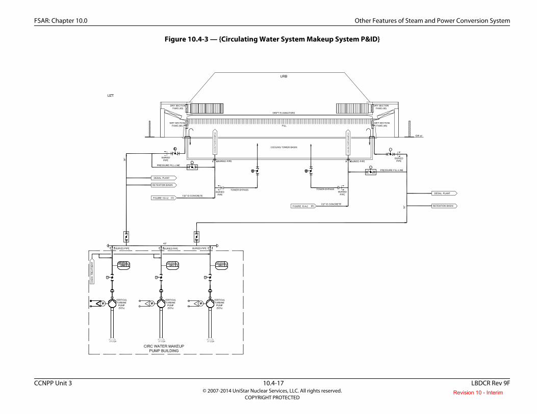
Makeup water for the CWS is taken from the Chesapeake Bay by pumps at a maximum rate of approximately 47,383 gpm (179,365 lpm). This rate is based on maintaining the CWS and supplying the desalinization plant and accounting for seepage. Three 50% capacity vertical CWS makeup pumps housed in the CWS makeup intake structure transfer water from the Chesapeake Bay to the cooling tower basin. Makeup water from the Chesapeake Bay is received into the intake structure via the common forebay shared with the UHS makeup water intake structure. The common forebay is shared between CWS makeup water system and UHS makeup water system. Two buried 60” safety related pipes provide a flow path for Chesapeake Bay water to enter the common forebay. Both pipes are designed to account for head losses in the pipe and provide sufficient flow for the CWS makeup and UHS makeup. Both pipes are normally in operation, however, either pipe can be isolated for maintenance as the other pipe is capable of providing 100% flow for CWS makeup and UHS makeup. Due to the head loss through the pipes, the design low water level at the common forebay for the UHS makeup intake is at EL. -8 ft NGVD29, which is 2 feet lower than the design low water level in the Chesapeake Bay of -6 ft NGVD29. The common forebay invert elevation is at -22.5 ft NGVD29, which provides ample additional margin in pump submergence during UHS operation with one or two intake pipes.The CWS makeup water intake structure houses two bar screens and two dual-flow traveling screens. The purpose of these screens is to prevent debris from passing into the circulating water system makeup pumps, circulating water pumps, condenser, and turbine building closed cooling heat exchangers. The screen wash system consists of two screen wash pumps (single shaft) that provide a pressurized spray to remove debris from the traveling screens. The CWS makeup system is shown in Figure 10.4-3. The CWS makeup water intake structure is shown in Figure 10.4-4 and Figure 10.4-5.
Blowdown from the cooling tower discharges to a common retention basin to provide time for settling of suspended solids and to permit further chemical treatment of the wastewater, if required. Discharge from the retention basin is routed through the seal well, then to the outfall pipe, where it disperses into the Chesapeake Bay. Discharge temperature is monitored prior to discharge into the bay. The blowdown flowpath, including the retention basin and seal well is shown in Figure 10.4-6. The outfall piping is shown in Figure 10.4-7.
The CWS chemical treatment system provides a means for adding chemicals to the CWS to maintain circulating water system chemistry within established limits to minimize fouling, inhibit scaling on the heat exchange surfaces, to control growth of bacteria, and to inhibit corrosion of piping materials.}
CC3-14-0083
Revision 10 - Interim

FSAR: Chapter 10.0 Other Features of Steam and Power Conversion System
CCNPP Unit 3 10.4-4 LBDCR Rev 9F© 2007-2014 UniStar Nuclear Services, LLC. All rights reserved.
COPYRIGHT PROTECTED
In addition, this COL Item is addressed by replacing the conceptual design information identified in double brackets in U.S. EPR FSAR Section 10.4.5 with plant specific information as discussed in the following sections.
10.4.5.2.2 Component Description
Cooling Towers
The U.S. EPR FSAR includes the following conceptual design information in Section 10.4.5.2.2 for the Cooling Towers:
[[The CWS has mechanical draft cooling towers, each with a basin and circulating water sump. Each sump houses a circulating water pump. The sumps are designed to provide sufficient submergence of the pump suction. Trash racks or suction screens are provided to prevent the ingestion of debris.]]
The above conceptual design information is replaced with site-specific information as follows:
{The CCNPP Unit 3 cooling tower is a plume-abated forced draft cooling tower. The tower structure dimensions are represented in Table 10.4-1 and will be surrounded by a wind wall. The tower has the ability to function as an all-wet system or a hybrid system.
The circulating water pump forebay, cooling tower, and cooling tower basin is comprised of reinforced concrete. The cooling tower basin is supported by a reinforced concrete foundation. Internal construction materials of the cooling tower include fiberglass-reinforced plastic (FRP) or polyvinyl chloride (PVC) for piping laterals, poly propylene for spray nozzles, and PVC for fill material and drift eliminators. Additionally, the heat exchangers for the cooling tower hybrid system are constructed of titanium or equivalent.
Heat dissipation from the CWS to the ambient air (primarily latent heat transfer with some sensible heat transfer) occurs by direct contact between the rising air and the circulating water falling from the tower spray nozzles.
The tower fill redirects the water falling through the tower into thin vertically oriented films, which maximizes surface area of water in contact with surrounding air. Multiple tower fans force the air from the tower vicinity into the tower, upward through the fill and falling water, and through the exit at the top of the tower.
The tower basin is located below the tower structure and serves as the collection point for the CWS cold water after it has fallen through the tower. At one end of the basin is the pump forebay, which is shaped and sloped to serve as the suction point for the CWS pumps. The basin is sized to meet pump suction head requirements, to prevent formation of harmful vortices at the pump suctions, and to provide sufficient volume to allow draindown of the circulating water system without overflow with the basin initially at the maximum operating water level. Basin level is controlled by a level control system.
Table 10.4-1 provides cooling tower design specification information.}
Circulating Water Pumps
The U.S. EPR FSAR includes the following conceptual design information in Section 10.4.5.2.2 for the Circulating Water Pumps:
CC3-09-0285
Revision 10 - Interim

FSAR: Chapter 10.0 Other Features of Steam and Power Conversion System
CCNPP Unit 3 10.4-5 LBDCR Rev 9F© 2007-2014 UniStar Nuclear Services, LLC. All rights reserved.
COPYRIGHT PROTECTED
[[The circulating water pumps are constant speed, vertical shaft type. The pumps are designed to operate under normal plant operating load conditions. Each pump has its suction located in its own pump bay. The pumps are designed to permit reverse flow.]]
The above conceptual design information is replaced with site-specific information as follows:
{Four 25% capacity vertical turbine pumps, each capable of delivering approximately 200,000 gpm (757,083 lpm), are used to provide flow for the CWS. The pumps draw water from the cooling tower basin and deliver it to two concrete supply pipes each 11 feet (3.3 meters) in diameter. Each pump is driven by a motor rated at 11,000 HP (8 MW). The pumps are sized to provide sufficient head to overcome energy losses due to friction, piping elevation changes, and static head requirements for the cooling tower. The circulating water pump materials are compatible with the circulating water quality. Pump components in contact with the circulating water (i.e., suction bell, impeller, impeller shrouds, columns) are duplex stainless steel or equivalent.}
Cooling Tower Makeup System
The U.S. EPR FSAR includes the following conceptual design information in Section 10.4.5.2.2 for the Cooling Tower Makeup System:
[[The cooling tower makeup system is site-specific and will be designed to provide adequate makeup flow to the cooling tower basins.]]
The above conceptual design information is replaced with site-specific information as follows:
{The CCNPP Unit 3 CWS makeup system functions to replace CWS water losses due to evaporation, blowdown, and drift associated with the cooling tower as well as leakage and seepage losses from the basin and system piping and components. Additionally, the CWS makeup system provides water to the desalinization plant for water treatment. Makeup rate is controlled by the tower basin level control system and the makeup system control valves. Three 50% capacity vertical CWS makeup pumps housed in the CWS makeup water intake structure transfer water from the Chesapeake Bay to the cooling tower basin. The CWS makeup water intake structure houses two bar screens and two dual-flow traveling screens. The purpose of these screens is to prevent debris from passing into the CWS makeup pumps, circulating water pumps, condenser, and turbine building closed cooling heat exchangers. The screen wash system consists of two screen wash pumps (single shaft) that provide a pressurized spray to remove debris from the traveling screens. The CWS makeup system is shown in Figure 10.4-3. The CWS makeup water intake structure is shown in Figures 10.4-4 and 10.4-5. The CCNPP Unit 3 CWS makeup system piping is compatible with the water chemistry of the Chesapeake Bay and as such is composed of either high density polyethylene (HDPE) or FRP pipe. The CWS makeup system pump components in contact with the Chesapeake Bay water are of similar materials as described for the CWS pumps.}
Chemical Treatment System
The U.S. EPR FSAR includes the following conceptual design information in Section 10.4.5.2.2 for the Chemical Treatment System:
[[Water treatment for the CWS is based on site makeup water chemistry, blowdown requirements, environmental regulations and system materials.]]
CC3-14-0083
Revision 10 - Interim

FSAR: Chapter 10.0 Other Features of Steam and Power Conversion System
CCNPP Unit 3 10.4-6 LBDCR Rev 9F© 2007-2014 UniStar Nuclear Services, LLC. All rights reserved.
COPYRIGHT PROTECTED
The above conceptual design information is replaced with site-specific information as follows:
Chemical treatment system pumps, valves, tanks, instrumentation, and controls provide the means of monitoring water chemistry and adding required chemicals into the CWS in order to minimize corrosion, prevent scale formation, and limit biological fouling.
The U.S. EPR FSAR includes the following COL Item in Section 10.4.5.2.2 for the Chemical Treatment System:
A COL applicant that references the U.S. EPR design certification will provide the specific chemicals used to support the chemical treatment system as determined by the site-specific water conditions.
This COL Item is addressed as follows:
{At CCNPP Unit 3, water quality control focuses on corrosion/scaling control and preventing silt deposition and biofouling control. The chemicals chosen for use are compatible with the system wetted surfaces and are monitored for optimizing chemical feeds with periodic testing of metallic parts (using immersed metal coupons) to minimize metal loss (measured in mils per year) from the system.}
The specific chemicals and addition rates used in the system are determined and adjusted as required by evaluation of periodic water chemistry analyses.
{At CCNPP Unit 3, the following chemicals will be added to various points (makeup intake and cooling tower.)
♦ Biocide – Sodium Hypochlorite – continuous dosing at the make-up intake, shock dosing to the circulating water pump suction in the forebay.
♦ Algaecide – non-oxidizing biocide – slug feed to the circulating water pump suction in the forebay.
♦ pH adjuster – sulfuric acid - continuous feed of sulfuric acid to the circulating water pump suction in the forebay.
♦ Corrosion inhibitor* – proprietary (supplier-specific) - continuous feed of proprietary chemical to the circulating water pump suction in the forebay.
♦ Scale inhibitor* – proprietary (supplier-specific) - continuous feed of proprietary (supplier-specific) chemical to the circulating water pump suction in the forebay.
♦ Dispersant – proprietary (supplier-specific) - slug feed of proprietary chemical to the circulating water pump suction in the forebay.
* In general, only corrosion inhibitor or scale inhibitor will be used, not both.
The National Pollution Discharge Elimination System (NPDES) Permit will have a limit on residual chlorine, which will result in the need to add a chemical such as sodium bisulfite at the retention basin outlet or other appropriate point to ensure that the plant discharge meets the limit. These chemicals will be stored on site.
Revision 10 - Interim

FSAR: Chapter 10.0 Other Features of Steam and Power Conversion System
CCNPP Unit 3 10.4-7 LBDCR Rev 9F© 2007-2014 UniStar Nuclear Services, LLC. All rights reserved.
COPYRIGHT PROTECTED
The following samples and analyses are typical for plant operation and control. For environmental compliance, the parameters provided below are typically monitored and analyzed. Parameters monitored, frequency of monitoring/analysis, and analysis methods are subject to change based on the NPDES Permit and regulatory limits in effect at the time.
Condenser Cold Water Inlet
♦ pH (continuous and grab), pH probe
♦ Conductivity (continuous and grab), conductivity cell
♦ Calcium hardness (grab), titration
♦ Total hardness (grab), titration
♦ Iron (grab), colorimetric spectrometry
♦ Silica (grab), colorimetric spectrometry
♦ Residual chlorine (continuous and grab), ORP cell, colorimetric spectrometry
♦ Turbidity (grab), direct read light scatter
♦ Bacteria (grab), plate count
♦ Inhibitor level (grab), colorimetric spectrometry
♦ Dispersant level (grab), colorimetric spectrometry
Sample Tap at Line to Seal Well
♦ pH (continuous, grab), pH probe
♦ Chlorine residual (grab and continuous), ORP cell, colorimetric spectrometry
♦ TSS (grab), filter and gram balance
♦ Oil & Grease, extraction or other
♦ Salinity (grab), conductivity relation
♦ Phosphate (grab), colorimetric spectrometry
♦ Total nitrogen (grab), digestion/colorimetric spectrometry
♦ BOD5 (grab), digestion
♦ Metals (grab), atomic absorption
♦ Priority pollutants (grab), chromatograph, others
♦ Biological toxicity (grab), fathead minnow, others
Revision 10 - Interim

FSAR: Chapter 10.0 Other Features of Steam and Power Conversion System
CCNPP Unit 3 10.4-8 LBDCR Rev 9F© 2007-2014 UniStar Nuclear Services, LLC. All rights reserved.
COPYRIGHT PROTECTED
Based on the NPDES permit, additional environmental compliance monitoring may be required at point sources, such as sump discharges to oil/water separator and desalination plant concentrate.}
Cooling Tower Blowdown System
The U.S. EPR FSAR includes the following conceptual design information in Section 10.4.5.2.2 for the Cooling Tower Blowdown System:
[[The cooling tower blowdown system is site-specific, and along with the makeup system will be designed to maintain the concentration of dissolved solids in the CWS within acceptable limits.]]
The above conceptual design information is replaced with site-specific information as follows:
{The nonsafety-related CWS blowdown system consists of piping, valves, and associated instrumentation and controls that convey water from the CWS cooling tower basin to the retention basin prior to its discharge through the seal well to the Chesapeake Bay. Blowdown rate from the cooling tower is controlled by a motor operated control valve. The CWS blowdown system piping is compatible with the circulating water and as such is composed of either HDPE or FRP pipe.
The retention basin, seal well, and outfall are important components of the CWS.
CWS Retention Basin
The CWS retention basin serves as a collection point for the following discharge sources prior to their discharge in the Chesapeake Bay:
♦ CWS cooling tower blowdown
♦ Essential Service Water System (ESWS) cooling tower blowdown
♦ Other plant discharges
The basin serves as a means of settling out suspended solids from plant discharges.
One discharge pipe conveys the discharge flow from the retention basin at plant grade to the seal well. Treated water from the liquid radwaste system (see Section 11.2) acceptable for discharge joins the main discharge flow between the retention basin and the seal well. The driving force for flow is gravity.
CWS Seal Well
The CWS seal well serves as a means of reducing discharge flow velocity prior to its exit from the outfall structure into the Chesapeake Bay. Discharge flow is transferred by a 30-inch (76-cm) discharge header from the retention basin at plant grade to the seal well. Seal well elevation is based on limiting flow velocity in the discharge piping to less than 10 feet per second (3 m/s) and on ensuring the downstream discharge piping remains full of water. The water in the seal well is conveyed to the outfall. The driving force for flow is gravity.
CC3-09-0285
Revision 10 - Interim

FSAR: Chapter 10.0 Other Features of Steam and Power Conversion System
CCNPP Unit 3 10.4-9 LBDCR Rev 9F© 2007-2014 UniStar Nuclear Services, LLC. All rights reserved.
COPYRIGHT PROTECTED
CWS Outfall
The CWS outfall consists of a discharge header, diffuser nozzles, valves and associated instrumentation and controls for the control and monitoring of discharge flow into the Chesapeake Bay.
The outfall is designed to meet all applicable navigation and maintenance criteria to provide an acceptable mixing zone for the thermal plume. One 30-inch (76-cm) diameter discharge header conveys flow from the CWS seal well into the Chesapeake Bay. The piping extends approximately 550 feet (168 m) into the bay to ensure that at least 10 ft (3 m) of water exists above the top of the diffuser nozzles. Figure 10.4-6 provides a simplified schematic of the discharge flow path to the Chesapeake Bay. Figure 10.4-7 provides a plan and section view of the diffuser and discharge piping.
Flow in the discharge header is directed to three 16-inch (41-cm) diameter diffuser nozzles that increase the flow velocity and serve as the exit point for discharges into the bay. The centerline elevation of the discharge is approximately 3 ft (1 m) above the bay bottom elevation. Exit velocity for the discharge flow has been evaluated to be adequate for thermal mixing purposes.}
Piping and Valves
The U.S. EPR FSAR includes the following conceptual design information in Section 10.4.5.2.2 for the Piping and Valves:
[[A butterfly valve is installed downstream of each circulating water pump.]] Isolation valves are installed at the inlets of the low pressure condenser water box and outlets of the high pressure condenser water box. [[Each cooling tower riser also has a butterfly valve that serves to isolate the cooling tower cell during maintenance activities. The butterfly valves contained in the CWS are designed to operate under normal plant operating load conditions. Valve opening and closing times are chosen to reduce water hammer effects.]]
The above conceptual design information is replaced with site-specific information for the plant as follows:
{The U.S. EPR FSAR description provided above is applicable to the CCNPP Unit 3 CWS and is incorporated by reference.}
The U.S. EPR FSAR includes the following COL Item in Section 10.4.5.2.2 for Piping and Valves:
A COL applicant that references the U.S. EPR design certification will provide the site-specific CWS piping design pressure.
This COL Item is addressed as follows:
{The CCNPP Unit 3 CWS piping design pressure is 150 psig (1034 kPa-gauge).}
Vacuum Breaker
No departures or supplements.
Revision 10 - Interim

FSAR: Chapter 10.0 Other Features of Steam and Power Conversion System
CCNPP Unit 3 10.4-10 LBDCR Rev 9F© 2007-2014 UniStar Nuclear Services, LLC. All rights reserved.
COPYRIGHT PROTECTED
Condenser Tube Cleaning System
No departures or supplements.
Vacuum Priming System
The U.S. EPR FSAR includes the following COL Item in Section 10.4.5.2.2 for the Vacuum Priming System:
If a vacuum priming system is required, a COL applicant that references the U.S. EPR design certification will provide the site-specific information.
This COL Item is addressed as follows:
{A vacuum priming system is not required for filling and venting of the CWS in preparation for system startup, or during normal system operation. The CWS is filled and vented using gravity fill from the circulating water pump forebay and using the pressure fill line with the CWS makeup water system pumps. The system is fully primed when fill water exits the condenser waterbox vent valves, CLCWS heat exchanger vent valves, and cooling tower spray nozzles.
During normal system operation, either through the tower spray headers or the tower bypass line, the condenser and heat exchangers are under positive pressure. Therefore no vacuum priming system is required.}
Vents and Drains
No departures or supplements.
10.4.5.2.3 System Operation
{No departures or supplements.}
10.4.5.3 Safety Evaluation
The U.S. EPR FSAR includes the following COL Item and conceptual design information in Section 10.4.5.3:
A COL applicant that references the U.S. EPR design certification will provide information to address the potential for flooding of safety-related equipment due to failure of the site-specific CWS.
[[Means are provided to prevent or detect and control flooding of safety-related areas so that the intended safety function of a system or component will not be diminished due to leakage from the CWS.]]
[[Malfunction or failure of a component or piping in the CWS, including an expansion joint, will not produce unacceptable adverse effects on the functional performance capabilities of safety-related systems or components.]]
CC3-09-0284
CC3-09-0284
Revision 10 - Interim

FSAR: Chapter 10.0 Other Features of Steam and Power Conversion System
CCNPP Unit 3 10.4-11 LBDCR Rev 9F© 2007-2014 UniStar Nuclear Services, LLC. All rights reserved.
COPYRIGHT PROTECTED
The above COL Item is addressed and the conceptual design information is replaced with site-specific information as follows:
{Internal flooding of the Turbine Building due to an un-isolatable break or crack in a circulating water system pipe or failure of a CWS component, including expansion joints, does not result in damage to safety-related SSCs. Below the main steam piping penetrations, no direct pathway through which flooding could spread exists between the Turbine Building and adjacent structures that house safety-related SSCs. No safety-related SSCs reside in the Turbine Building.
Flood waters, resulting from a CWS pipe failure inside the Turbine Building, would exit through relief sidings installed on the north and west sides of the Turbine Building. The relief sidings open under the hydrostatic pressure created by the CWS pipe failure flood waters in the Turbine Building. Relief sidings are installed on approximately 160 ft of the north wall (starting from the western corner and excluding the stair tower), and on the entire west wall of 180 feet to allow flood water to exit the Turbine Building in the event of a rupture in the CWS piping.
As shown in Figure 2.5-173, the yard area north of the Turbine Building is surrounded by three roads: on the west, north, and east sides. The eastern side road is the major flood drainage boundary between the Turbine Building and Reactor Building areas. This road has the highest crown elevation and the north side road (drainage side) has the lowest crown elevation. The yard area north of the Turbine Building is graded toward the north road to prevent floods from overtopping the east road and adversely affecting safety-related SSCs. To reduce the flooding level from a postulated CWS pipe break, finish grade elevation on the north side of the Turbine Building is lowered by 2 feet to Elevation 83 ft NGVD29 and sloped toward the north road and the crest of the northern side road is set at Elevation 82.0 ft NGVD29. The general yard grading near the Turbine Building is arranged in a way that flood water exiting the relief siding on the northern side of the building will flow primarily in a northerly direction. In addition to the flood barrier provided by the eastern boundary road, and to direct the flood flow away from safety-related SSCs and avoid flood water from flowing toward the east through storm drain (where the Reactor Building is located), the finish grade between the north wall of the Turbine Building and the southwest corner of the Essential Service Water (ESW) cooling tower, and between the two ESW cooling towers, is raised locally in the form of a berm. The berm will be constructed of compacted structural fill protected with concrete lining on all sides and with the top of the berm at Elevation 85.5 ft NGVD29; this will contain the maximum conservatively analyzed flood elevation of 85.0 ft NGVD29. These measures and other minor local grading in the yard area will convey the flood water in a northward direction and toward the northern drainage ditch (north ditch). The flood flow exiting the west side of the Turbine Building will be naturally diverted in two directions, to the north and the south by the enclosure walls of the transformers located west of the Turbine Building. These flow paths are farther away from the safety-related SSCs and have less flooding impact. For added conservatism, the flood analysis assumes that the maximum flood flow occurs along the flood path instantly. In reality, the cooling tower basin is the flood water source having a finite volume, with circulating water pumps tripping upon the drop of water level at the pumps to a pre-set minimum control condition. The entire flood period is short, with peak flow lasting only for a small period of the flood duration, even with the inclusion of small cooling tower makeup flow rate. The analysis, however, conservatively assumed the flood peak occurs instantly and did not account for the filling volumes of the buildings and the yard area and the decrease in the flood peak in the short period of flood event.
As the flood water flows northward from the Turbine Building, it will be confined by the two ESW buildings, the east road and the berm along the east side. On the west side, the flow will follow the topography between the west road and the transformers area.
CC3-11-0191,CC3-14-0083
CC3-11-0081,CC3-11-0191
Revision 10 - Interim

FSAR: Chapter 10.0 Other Features of Steam and Power Conversion System
CCNPP Unit 3 10.4-12 LBDCR Rev 9F© 2007-2014 UniStar Nuclear Services, LLC. All rights reserved.
COPYRIGHT PROTECTED
The flood analysis indicates that the postulated CWS piping rupture in the Turbine Building will not impact any safety-related SSCs. The safety-related SSCs in the Nuclear Island are protected by the berm that extends between the Turbine Building and the ESW cooling tower and between the two ESW cooling towers. The two safety-related ESW cooling towers on the north side of the Turbine Building are not affected by flood flow because their entrance opening is 14.0 ft above finish grade. Additionally, there are no safety-related below grade penetrations located in the ESW Building walls that are exposed to the flood waters, and below grade penetrations (in the walls that are not exposed to flood waters) are sealed to prevent leakage of water into the buildings. Therefore, the flood water from a postulated break of a CWS pipe in the Turbine Building, conservatively evaluated as exiting toward the yard area on the north side of the building, will not create a flood hazard to safety-related SSCs.
Considering the cooling tower yard topography and cooling tower basin elevation (see Figure 2.4-7 and Figure 2.5-162), a collapse in a cooling tower basin wall would result in flood water flowing toward the cooling tower area western boundary to design drainage ditches and away from the power block area; consequently, there is no impact to safety-related SSCs in the power block area due to a postulated collapse of a cooling tower basin wall.
Flooding resulting from a postulated CWS pipe failure in the yard area adjacent to the Switchgear Building will not result in a flood hazard to safety-related SSCs. The finish grade topography along the CWS pipe route is designed such that surface runoff is directed to the south away from the power block and toward drainage ditches (see Figure 2.4-16 and Figure 2.5-162). To assess the effect of a flood resulting from a postulated CWS pipe failure in the yard area next to the non-safety related Switchgear Building (the closest CW pipe point to the power block area), a flood analysis was performed to determine the flood level. From the results of this analysis, the calculated maximum localized flood level at the non-safety related Switchgear Building (flood origination location) is Elevation 84.2 feet NGVD29. The flood water both spreads and deceases in level as it flows downward and toward the southern drainage path. The respective flood level over the southern perimeter road is at Elevation 83.2 ft NGVD29 and the direction of the flow is away from the power block area. Safety-related structures are located a few hundred feet away from this area and are protected by the high crown of the east side perimeter road and by having a design floor elevation of 84.6 feet NGVD29, which is above the maximum calculated flood elevation. Consequently, the flood water from a postulated break of a CWS pipe in the yard area will not reach the power block area and will not create a flood hazard to safety-related SSCs.}
10.4.5.4 Inspection and Testing Requirements
No departures or supplements.
10.4.5.5 Instrumentation Requirements
The U.S. EPR FSAR includes the following conceptual design information in Section 10.4.5.5:
[[Pressure is measured at the discharge of each circulating water pump. Temperature is measured at the condenser inlet and outlet for each tube bundle.]] The circulating water is also monitored for pH and conductivity. [[Permanent flowmeters measure individual circulating pump flow and total flow to the turbine condenser. Access ports allow temporary flowmeters to be installed in the main circulating water piping. Cooling tower basin level is monitored and used to control makeup flow. Blowdown is manually adjusted as required to maintain desired water chemistry.]]
CC3-11-0081,CC3-11-0191,CC3-14-0083
CC3-09-0284,CC3-11-0081,CC3-14-0083
CC3-09-0284,CC3-11-0081,CC3-14-0083
Revision 10 - Interim

FSAR: Chapter 10.0 Other Features of Steam and Power Conversion System
CCNPP Unit 3 10.4-13 LBDCR Rev 9F© 2007-2014 UniStar Nuclear Services, LLC. All rights reserved.
COPYRIGHT PROTECTED
The above conceptual design information is replaced with site-specific information as follows:
{Instrumentation and controls for the CWS include provisions for remote and local control and monitoring of parameters such as pressure, temperature, flow, etc. Motor winding temperature sensors mounted at various locations in the motors along with bus power and breaker position provide remote control, indication, and alarm of the circulating water pumps.
The opening and closing of motor operated valves located at each pump’s discharge; on the cooling tower bypass; at the inlet and outlet of the condensers and at various other points within the process system are remotely controlled and monitored, but can be manually operated via valve mounted hand wheels.
System temperature, pressure and flow are monitored in each of the circulating water pump discharge lines as well as at various other points. The cooling tower basin level is controlled by varying the makeup water flow as monitored by the basin level control system. Blowdown flow rate is monitored and controlled by adjusting the position of the blowdown isolation valve. Differential pressure across the traveling screens provides indication of fouling and initiates the screen cleaning system.}
10.4.5.6 References
{No departures or supplements}
10.4.6 Condensate Polishing System
No departures or supplements.
10.4.7 Condensate and Feedwater System
No departures or supplements.
10.4.8 Steam Generator Blowdown System (PWR)
No departures or supplements.
10.4.9 Emergency Feedwater System
No departures or supplements.
Revision 10 - Interim

FSAR: Chapter 10.0 Other Features Of Steam And Power Conversion System
CCNPP Unit 3 10.4-14 LBDCR Rev 9F© 2007-2014 UniStar Nuclear Services, LLC. All rights reserved.
COPYRIGHT PROTECTED
Table 10.4-1 — {Circulating Water System Cooling Tower Design Specifications}
Design Conditions Mechanical Draft Cooling Tower
Number of Towers 1
Heat Load 1.108E+10 BTU/hr (2.792E+09 Kcal/hr)
Circulating Water Flow 785,802 gpm (2,974,584 lpm)
Cycles of Concentration—Normal 2
Evaporative Losses (wet) (1) 19,700 gpm (74,573 lpm)
Evaporative Losses (wet+dry) (1) 18,000 gpm (68,138 lpm)
Blowdown Rate (wet) (1) 19,696 gpm (74,558 lpm)
Blowdown Rate (wet+ dry) (1) 17,996 gpm (68,122 lpm)
Drift Rate <0.0005%
Drift Losses (2) 4 gpm (16 lpm)
Approximate Dimensions—Height 177 ft (54 m)
Approximate Dimensions—Diameter 546 ft (167 m) (at the base)
Design Range 28°F (15.6°C)
Design Approach 10°F (5.6°C)
Air Flow Rates (wet/dry) (1) (3) 69,177,600 acfm (1,958,892 m3 per min) wet section fans54,096,000 acfm (1,531,829 m3 per min) dry section fans
Note:
(1) Based on design ambient conditions of 100°F Dry Bulb and coincident 77°F Wet Bulb (78°F inlet).
(2) Reported drift losses are based on 800,000 gpm CWS flow.
(3) Based on air exit density of 0.0817 lbm/ft3 for wet operation and 0.0757 lbm/ft3 for dry operation.
Revision 10 - Interim

FSAR: Chapter 10.0 Other Features of Steam and Power Conversion System
CCNPP Unit 3 10.4-15 LBDCR Rev 9F© 2007-2014 UniStar Nuclear Services, LLC. All rights reserved.
COPYRIGHT PROTECTED
Figure 10.4-1 — {Circulating Water System P & ID (Circulating Water Pump Building)}CC3-11-0081
Revision 10 - Interim

FSAR: Chapter 10.0 Other Features of Steam and Power Conversion System
CCNPP Unit 3 10.4-16 LBDCR Rev 9F© 2007-2014 UniStar Nuclear Services, LLC. All rights reserved.
COPYRIGHT PROTECTED
Figure 10.4-2 — {Circulating Water System P & ID (Turbine Building)}
Revision 10 - Interim
FSAR: Chapter 10.0 Other Features of Steam and Power Conversion System
CCNPP Unit 3 10.4-17 LBDCR Rev 9F© 2007-2014 UniStar Nuclear Services, LLC. All rights reserved.
COPYRIGHT PROTECTED
Figure 10.4-3 — {Circulating Water System Makeup System P&ID}
Revision 10 - Interim

FSAR: Chapter 10.0 Other Features of Steam and Power Conversion System
CCNPP Unit 3 10.4-18 LBDCR Rev 9F© 2007-2014 UniStar Nuclear Services, LLC. All rights reserved.
COPYRIGHT PROTECTED
Figure 10.4-4 — {Circulating Water System Makeup Pump Intake Structure (Plan View)}CC3-10-0009
Revision 10 - Interim

FSAR: Chapter 10.0 Other Features of Steam and Power Conversion System
CCNPP Unit 3 10.4-19 LBDCR Rev 9F© 2007-2014 UniStar Nuclear Services, LLC. All rights reserved.
COPYRIGHT PROTECTED
Figure 10.4-5 — {Circulating Water System Makeup Pump Intake Structure (Section View)}CC3-10-0009
Revision 10 - Interim

FSAR: Chapter 10.0 Other Features of Steam and Power Conversion System
CCNPP Unit 3 10.4-20 LBDCR Rev 9F© 2007-2014 UniStar Nuclear Services, LLC. All rights reserved.
COPYRIGHT PROTECTED
Figure 10.4-6 — {Circulating Water System Blowdown Flowpath}
Revision 10 - Interim

FSAR: Chapter 10.0 Other Features of Steam and Power Conversion System
CCNPP Unit 3 10.4-21 LBDCR Rev 9F© 2007-2014 UniStar Nuclear Services, LLC. All rights reserved.
COPYRIGHT PROTECTED
Figure 10.4-7 — {Circulating Water System Plant Discharge}
Revision 10 - Interim