final spring 2012 composite lab 2 ahmedawad
DESCRIPTION
MetrologyTRANSCRIPT

1
llDe = 0.0131 * P * (OeRlght + 6£hert)5 = De+ d (1 + cosecs) - ~ cote
Someuseful relations:
If this screw is to fit in a nut having 14.260±O.035 mm pitch diameter,Checkwhether the screw will lit fully, partially or will not fit at al/ whenengagedwith the nut.
(d) Calculate the virtual effective diameter of M16*1.5 screw if the reading over threewires placed over the thread is 17.019 mm. The wires having 1.35 mm diameter, theflank angles of the thread were 29.s° and 30.5° , and the pitch of the thread whencheckedalong the teeth were:
1.502 1.496 1.504 1.501 1.500 1.503 1,495 1.502 mm
(c) Describe - in detail ,using a -neat sketch- how can the pjtch measuring machine beused to measure the pitch of an internal thread.
(b) In thread measurement using hand tools, using a neat sketch - deduce a formula tocalculate the effect of thread included angle error on the measured pitch diameter.
(a) A small ball of dia, d 1 was placed in the slot shown andthe height MI was measured from the reference plateusing a height vernier. Then a bigger ball of dia, d2 wasplaced in the slot and the height M2 was measured. It'srequired to calculate the slot angle.
Question (1) (Mark =25% of total credit)
The exam consists of 4 four questions in four pages.
Examination's duration: 3Hr .
~~lu~,--..ut~
i~l A<lu.Wl~l).;
MANF 480 : Composite Lab Il (Metrology)Final Exam: spring 2012Dr. M. Adel RizkDr. Tamer Hassan
Faculty of EngineeringCredit Hours EngineeringPrograms
..

2
It Is required to;-• Draw a neat sketch showing the setting of the height gauge over the gear tooth flank.• Determine the deviations of the height gauge readings from the theoretical once.• Plot the accumulated deviatIon versus the rotation angle.'!( Determine the error in tooth profile and basecircle diameter.
Angle e 90 95 100 105 110 115Deg I
HeIght (h) 200.00 205.00 210.00 215.00 220.00 225.00mm
(d) A dividing head and height gauge were used to check the accuracy of a spur gear of 60'tooth and 20 deg pressure angle. Reading taken by vernier caliper over the outsidediameter of the gear was 124.03 mm The gear was fixed on a standard mandrel whichheld in the dividing head. The knife edge of the height gauge is made tangent to the gearflank and the Readings of the dividing head and the height gauge were observed. Theexperimental readings were listed in the following table:-
It is required to determfne the following:-• Error in span length• Error in base pitch.
~
Error in tooth thickness at the pitch circle.Error in base circle diameter.Error in the pressure angle.
Note: ( Derive the usedanalytic expressions}...
(c) A vernier caliper, and gear span micrometer were used to check the accuracy of a spurgear of nominal pressure angle 200• The experimental readings were as follows:-
- No of teeth 34 teeth.- Caliper reading over the addendum diameter 144.04 mm- Micrometer average reading over 4 teeth 43.20 mm- Micrometer average reading over 5 teeth 55.10 mm
(b) Describe the gear meshing test (gear rolling test), and explain what is meant by tooth totooth composite error, and total composite error.
Question (2) (Mark = 350/0 of total credit)(a) With the aid of neat sketches, describ¬ in detail an experiment to determine the
concentricity error between the gear bore and its pitch circle.
Faculty of EngineeringCredit Hours Engineering Programs
~~w~l.~l~
I.~l Ai4UWl ~~
3
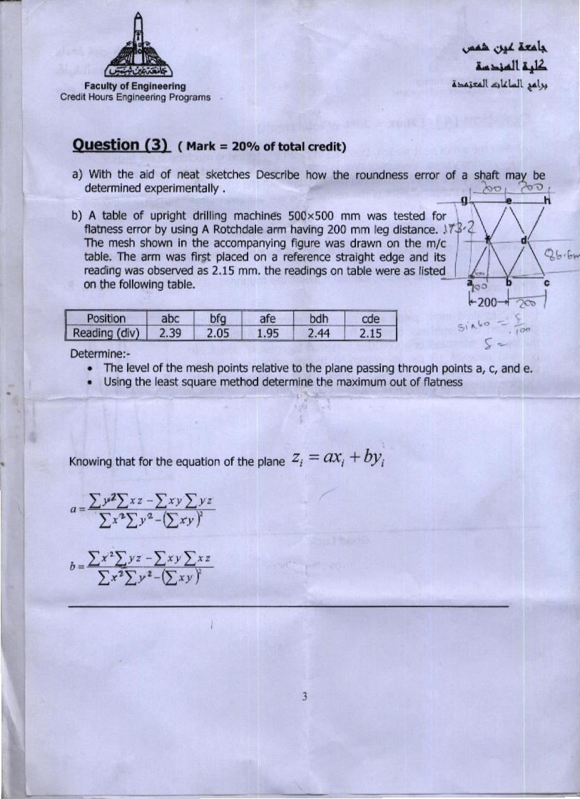
Knowing that for the equation of the plane Zi = aXi +by;
Determine:-• The level of the mesh points relative to the plane passingthrough paints a, c, and e.• Using the least square method determine the maximum out of flatness
2.151.952.05 2.442.39cdebdhafeabc bf
a) With the aid of neat sketches Describe how the roundness error of a shaft ~a?>bedetermined experimentally . ~ l~ VJ
b) A table of upright drilling machines 500x500 mm was tested for 1" \ /flatness error by using A Rotchdale arm having 200 mm ~egdistance•..\1. ' ~The mesh shown in the accompanying figure was drawn on the m/c T d\ ~table. The arm was fir~t placed on a reference straight edge and its I ~ b 'breading was observed as 2.15 mm. the readings on table were as listed I ·~ / -on the following table. -~"'O ,____J
~200-tl~ I
Question (3) (Mark = 20% of total credit)
~,,*,lu~Lt.~t~
i~l41.LWl t"lj,.Faculty of EngineeringCredit Hours Engineering Programs

4
10um
I
.-e=~
(d) A Standard work piece was especially made to be used incanoranon of rouqbness testers. The profile of the surface wasmade to be consisted of successive isoscelestriangles of height 20IJm and base of 10 IJm as shown in the accompanying figure.Consider a cut-off of 0.8 mm, determine the values of theroughnessparameters Ra, Rz (ISO), Rz (D1N), and Rt..,
( c) With the aid of neat sketch, explain in detail the roughness parameters; Ra, Rz (ISO), s,(DIN), and Rt .
(b) With the aid of neat sketch, explain the stylus method for roughness measurement.
(a) With the aid of neat sketch, Describe in detail the following machine static tests:-• Testing the squarenessof drilling machine spindle axis and table surface.• Testing the parallelism of the milling table with the spindle axis.• Testing the parallelism of the center I<l;thespindle axis with the saddle guide-ways.
Question (4) (Mark = 200/0 of total credit)
Faculty of EngineeringCredit Hours Engineerrng Programs
~,,*,kA~'-~t~
l~t~tLWl~W
-