finder relay 95 series - sockets and accessories for 40 ... 95.63 40.31 screw terminal (box clamp)...
TRANSCRIPT

95.65
95.63
95.55.3
95.55
95.95.3
95.85.3
95 Series - Socket overview for 40 series relays
See page 10
See page 11
See page 12
See page 15
9
See page 13
See page 14
Module Socket Relay Description Mounting Accessories99.01 95.63 40.31 Screw terminal (Box clamp) socket Panel or 35 mm rail - Coil indication and EMC
- Top terminals - Contacts (EN 60715) mount suppression modules- Bottom terminals - Coil - Metal retaining clip
Module Socket Relay Description Mounting Accessories99.02 95.03 40.31 Screw terminal (Box clamp) socket Panel or 35 mm rail - Coil indication and EMC
95.05 40.51 - Top terminals - Contacts (EN 60715) mount suppression modules40.52 - Bottom terminals - Coil - Jumper link40.61 - Timer modules
- Plastic retaining and release clip
Module Socket Relay Description Mounting Accessories99.80 95.83.3 40.31 Screw terminal (Box clamp) socket Panel or 35 mm rail - Coil indication and EMC
95.85.3 40.51 95.83.3 wiring: (EN 60715) mount suppression modules40.52 - Top terminals - Contacts - Jumper link40.61 - Bottom terminals - Coil - Plastic retaining and release
clip
Module Socket Relay Description Mounting Accessories99.80 95.93.3 40.31 Screw terminal (Box clamp) socket Panel or 35 mm rail - Coil indication and EMC
95.95.3 40.51 - Top terminals - Contacts (EN 60715) mount suppression modules40.52 - Bottom terminals - Coil - Jumper link40.61 - Plastic retaining and release
clip
Module Socket Relay Description Mounting Accessories99.02 95.55 40.51 Screwless terminal socket Panel or 35 mm rail - Coil indication and EMC
40.52 - For fast cable connections (EN 60715) mount suppression modules40.61 - Top terminals - Contacts - Timer modules
- Bottom terminals - Coil - Plastic retaining and release clip
Module Socket Relay Description Mounting Accessories99.80 95.55.3 40.51 Screwless terminal socket Panel or 35 mm rail - Coil indication and EMC
40.52 For fast cable connections (EN 60715) mount suppression modules40.61 - Top terminals - Contacts - Plastic retaining and release
- Bottom terminals - Coil clip
See page 15
Module Socket Relay Description Mounting Accessories— 95.65 40.51 Screw terminal (Box clamp) socket Panel or 35 mm rail - Metal retaining clip
40.52 - Top terminals - Contacts (EN 60715) mount40.61 - Bottom terminals - Coil
See page 16
Module Socket Relay Description Mounting Accessories— 95.13.2 40.31 PCB socket PCB mounting - Metal retaining clip
40.41 - Plastic retaining clip— 95.15.2 40.51
40.5240.61
95.05
95.13.2
A2 A1 COIL
11 COM
NO
NC
14
12
95.03 95.05
95.05
10
99.02 coil indication and EMC suppression modules for 95.03 and 95.05 socketsDiode (+A1, standard polarity) (6...220)V DC 99.02.3.000.00LED (6...24)V DC/AC 99.02.0.024.59LED (28...60)V DC/AC 99.02.0.060.59LED (110...240)V DC/AC 99.02.0.230.59LED + Diode (+A1, standard polarity) (6...24)V DC 99.02.9.024.99LED + Diode (+A1, standard polarity) (28...60)V DC 99.02.9.060.99LED + Diode (+A1, standard polarity) (110...220)V DC 99.02.9.220.99LED + Varistor (6...24)V DC/AC 99.02.0.024.98LED + Varistor (28...60)V DC/AC 99.02.0.060.98LED + Varistor (110...240)V DC/AC 99.02.0.230.98RC circuit (6...24)V DC/AC 99.02.0.024.09RC circuit (28...60)V DC/AC 99.02.0.060.09RC circuit (110...240)V DC/AC 99.02.0.230.09Residual current by-pass (110...240)V AC 99.02.8.230.07
Approvals (according to type):
86 series timer modules(12…24)V AC/DC; Bi-function: AI, DI; (0.05s…100h) 86.30.0.024.0000(110...125)V AC; Bi-function: AI, DI; (0.05s…100h) 86.30.8.120.0000(230...240)V AC; Bi-function: AI, DI; (0.05s…100h) 86.30.8.240.0000
DC Modules withnon-standard polarity(+A2) on request.
Approvals (according to type):
95 Series - Sockets and accessories for 40 series relays
Approvals (according to type):
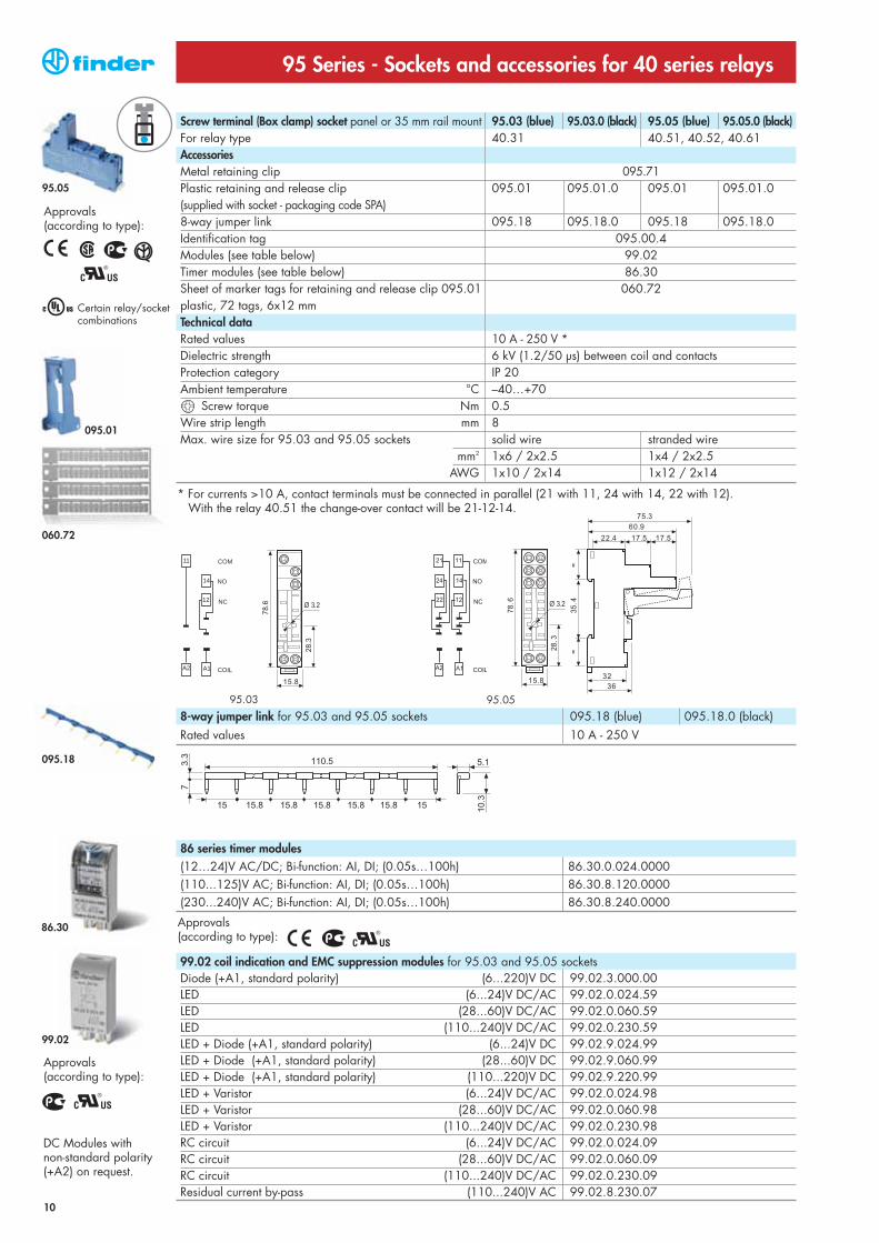
Screw terminal (Box clamp) socket panel or 35 mm rail mount 95.03 (blue) 95.03.0 (black) 95.05 (blue) 95.05.0 (black)For relay type 40.31 40.51, 40.52, 40.61AccessoriesMetal retaining clip 095.71Plastic retaining and release clip 095.01 095.01.0 095.01 095.01.0(supplied with socket - packaging code SPA)8-way jumper link 095.18 095.18.0 095.18 095.18.0Identification tag 095.00.4Modules (see table below) 99.02Timer modules (see table below) 86.30Sheet of marker tags for retaining and release clip 095.01 060.72plastic, 72 tags, 6x12 mmTechnical dataRated values 10 A - 250 V *Dielectric strength 6 kV (1.2/50 µs) between coil and contactsProtection category IP 20 Ambient temperature °C –40…+70
Screw torque Nm 0.5Wire strip length mm 8Max. wire size for 95.03 and 95.05 sockets solid wire stranded wire
mm2 1x6 / 2x2.5 1x4 / 2x2.5AWG 1x10 / 2x14 1x12 / 2x14
8-way jumper link for 95.03 and 95.05 sockets 095.18 (blue) 095.18.0 (black)Rated values 10 A - 250 V
* For currents >10 A, contact terminals must be connected in parallel (21 with 11, 24 with 14, 22 with 12).With the relay 40.51 the change-over contact will be 21-12-14.
Certain relay/socketcombinations
060.72
095.18
095.01
99.02
86.30

95.83.3 95.85.3
95.85.3
99.80 coil indication and EMC suppression modules for 95.83.3 and 95.85.3 socketsBlue*
Diode (+A1, standard polarity) (6...220)V DC 99.80.3.000.00LED (6...24)V DC/AC 99.80.0.024.59LED (28...60)V DC/AC 99.80.0.060.59LED (110...240)V DC/AC 99.80.0.230.59LED + Diode (+A1, standard polarity) (6...24)V DC 99.80.9.024.99LED + Diode (+A1, standard polarity) (28...60)V DC 99.80.9.060.99LED + Diode (+A1, standard polarity) (110...220)V DC 99.80.9.220.99LED + Varistor (6...24)V DC/AC 99.80.0.024.98LED + Varistor (28...60)V DC/AC 99.80.0.060.98LED + Varistor (110...240)V DC/AC 99.80.0.230.98RC circuit (6...24)V DC/AC 99.80.0.024.09RC circuit (28...60)V DC/AC 99.80.0.060.09RC circuit (110...240)V DC/AC 99.80.0.230.09Residual current by-pass (110...240)V AC 99.80.8.230.07
*Modules in Black housing are available on request.
Green LED is standard.Red LED availableon request.
11
Approvals (according to type):
95 Series - Sockets and accessories for 40 series relays
8-way jumper link for 95.83.3 and 95.85.3 sockets 095.08 (blue) 095.08.0 (black)Rated values 10 A - 250 V
Screw terminal (Box clamp) socket panel or 35 mm rail mount 95.83.3 (blue) 95.83.30 (black) 95.85.3 (blue) 95.85.30 (black)For relay type 40.31 40.51, 40.52, 40.61AccessoriesMetal retaining clip 095.71Plastic retaining and release clip 095.91.3 095.91.30 095.91.3 095.91.30(supplied with socket - packaging code SPA)8-way jumper link 095.08 095.08.0 095.08 095.08.0Identification tag 095.80.3Modules (see table below) 99.80Sheet of marker tags for retaining and release clip 095.91.3 060.72plastic, 72 tags, 6x12 mmTechnical dataRated values 10 A - 250 V *Dielectric strength 6 kV (1.2/50 µs) between coil and contacts (95.83.3 only)Protection category IP 20 Ambient temperature °C –40…+70
Screw torque Nm 0.5Wire strip length mm 7Max. wire size for 95.83.3 and 95.85.3 sockets solid wire stranded wire
m2 1x6 / 2x2.5 1x4 / 2x2.5AWG 1x10 / 2x14 1x12 / 2x14
* For currents >10 A, contact terminals must be connected in parallel (21 with 11, 24 with 14, 22 with 12).With the relay 40.51 the change-over contact will be 21-12-14.060.72
095.08
095.91.3
99.80
Approvals (according to type):
95.93.3 95.95.3
95.95.3
12
99.80 coil indication and EMC suppression modules for 95.93.3 and 95.95.3 socketsBlue*
Diode (+A1, standard polarity) (6...220)V DC 99.80.3.000.00LED (6...24)V DC/AC 99.80.0.024.59LED (28...60)V DC/AC 99.80.0.060.59LED (110...240)V DC/AC 99.80.0.230.59LED + Diode (+A1, standard polarity) (6...24)V DC 99.80.9.024.99LED + Diode (+A1, standard polarity) (28...60)V DC 99.80.9.060.99LED + Diode (+A1, standard polarity) (110...220)V DC 99.80.9.220.99LED + Varistor (6...24)V DC/AC 99.80.0.024.98LED + Varistor (28...60)V DC/AC 99.80.0.060.98LED + Varistor (110...240)V DC/AC 99.80.0.230.98RC circuit (6...24)V DC/AC 99.80.0.024.09RC circuit (28...60)V DC/AC 99.80.0.060.09RC circuit (110...240)V DC/AC 99.80.0.230.09Residual current by-pass (110...240)V AC 99.80.8.230.07
*Modules in Black housing are available on request.
Green LED is standard.Red LED availableon request.
95 Series - Sockets and accessories for 40 series relays
Approvals (according to type):
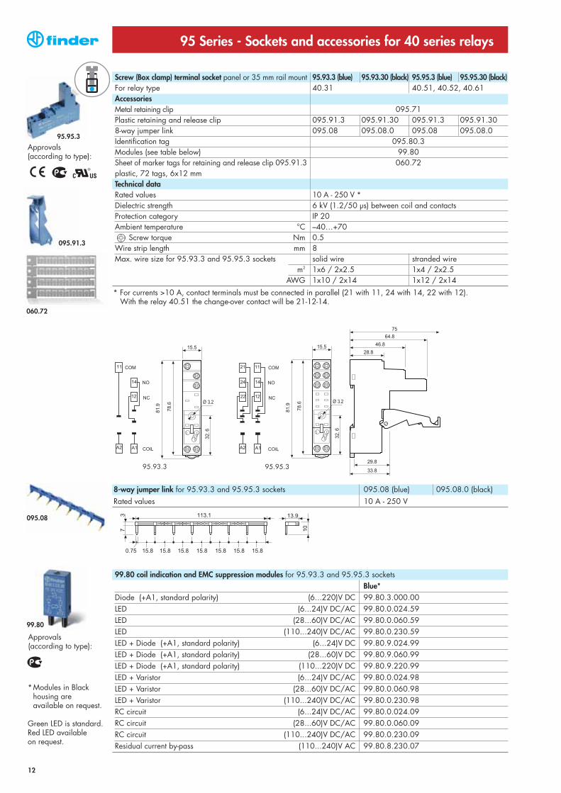
Screw (Box clamp) terminal socket panel or 35 mm rail mount 95.93.3 (blue) 95.93.30 (black) 95.95.3 (blue) 95.95.30 (black)For relay type 40.31 40.51, 40.52, 40.61AccessoriesMetal retaining clip 095.71Plastic retaining and release clip 095.91.3 095.91.30 095.91.3 095.91.308-way jumper link 095.08 095.08.0 095.08 095.08.0Identification tag 095.80.3Modules (see table below) 99.80Sheet of marker tags for retaining and release clip 095.91.3 060.72plastic, 72 tags, 6x12 mmTechnical dataRated values 10 A - 250 V * Dielectric strength 6 kV (1.2/50 µs) between coil and contactsProtection category IP 20 Ambient temperature °C –40…+70
Screw torque Nm 0.5Wire strip length mm 8Max. wire size for 95.93.3 and 95.95.3 sockets solid wire stranded wire
m2 1x6 / 2x2.5 1x4 / 2x2.5AWG 1x10 / 2x14 1x12 / 2x14
* For currents >10 A, contact terminals must be connected in parallel (21 with 11, 24 with 14, 22 with 12).With the relay 40.51 the change-over contact will be 21-12-14.
8-way jumper link for 95.93.3 and 95.95.3 sockets 095.08 (blue) 095.08.0 (black)Rated values 10 A - 250 V
060.72
095.08
095.91.3
99.80
Approvals (according to type):

95.55
13
Approvals (according to type):
95 Series - Sockets and accessories for 40 series relays
Screwless terminal socket panel or 35 mm rail mount 95.55 (blue) 95.55.0 (black)For relay type 40.51, 40.52, 40.61AccessoriesMetal retaining clip 095.71Plastic retaining and release clip 095.91.3(supplied with socket - packaging code SPA)Modules (see table below) 99.02Timer modules (see table below) 86.30Sheet of marker tags for retaining and release clip 095.91.3 060.72plastic, 72 tags, 6x12 mmTechnical dataRated values 10 A - 250 V *Dielectric strength 6 kV (1.2/50 µs) between coil and contactsProtection category IP 20 Ambient temperature °C –25…+70Wire strip length mm 8Max. wire size for 95.55 socket solid wire stranded wire
mm2 2x(0.2...1.5) 2x(0.2...1.5)AWG 2x(24...18) 2x(24...18)
* For currents >10 A, contact terminals must be connected in parallel (21 with 11, 24 with 14, 22 with 12).With the relay 40.51 the change-over contact will be 21-12-14.
99.02 coil indication and EMC suppression modules for 95.55 socketDiode (+A1, standard polarity) (6...220)V DC 99.02.3.000.00LED (6...24)V DC/AC 99.02.0.024.59LED (28...60)V DC/AC 99.02.0.060.59LED (110...240)V DC/AC 99.02.0.230.59LED + Diode (+A1, standard polarity) (6...24)V DC 99.02.9.024.99LED + Diode (+A1, standard polarity) (28...60)V DC 99.02.9.060.99LED + Diode (+A1, standard polarity) (110...220)V DC 99.02.9.220.99LED + Varistor (6...24)V DC/AC 99.02.0.024.98LED + Varistor (28...60)V DC/AC 99.02.0.060.98LED + Varistor (110...240)V DC/AC 99.02.0.230.98RC circuit (6...24)V DC/AC 99.02.0.024.09RC circuit (28...60)V DC/AC 99.02.0.060.09RC circuit (110...240)V DC/AC 99.02.0.230.09Residual current by-pass (110...240)V AC 99.02.8.230.07
86 series timer modules(12…24)V AC/DC; Bi-function: AI, DI; (0.05s…100h) 86.30.0.024.0000(110...125)V AC; Bi-function: AI, DI; (0.05s…100h) 86.30.8.120.0000(230...240)V AC; Bi-function: AI, DI; (0.05s…100h) 86.30.8.240.0000
DC Modules withnon-standard polarity(+A2) on request.
Approvals (according to type):
060.72
095.91.3
99.02
86.30
Approvals (according to type):

COM
NO
NC
COIL A1A2
1222
1424
1121
15.8
37.2
Ø 3.295.6
22.632.5
30.3
34.7
30.6
4 424.6
73.7
95.55.3
14
95 Series - Sockets and accessories for 40 series relays
99.80 coil indication and EMC suppression modules for 95.55.3 socketBlue*
Diode (+A1, standard polarity) (6...220)V DC 99.80.3.000.00LED (6...24)V DC/AC 99.80.0.024.59LED (28...60)V DC/AC 99.80.0.060.59LED (110...240)V DC/AC 99.80.0.230.59LED + Diode (+A1, standard polarity) (6...24)V DC 99.80.9.024.99LED + Diode (+A1, standard polarity) (28...60)V DC 99.80.9.060.99LED + Diode (+A1, standard polarity) (110...220)V DC 99.80.9.220.99LED + Varistor (6...24)V DC/AC 99.80.0.024.98LED + Varistor (28...60)V DC/AC 99.80.0.060.98LED + Varistor (110...240)V DC/AC 99.80.0.230.98RC circuit (6...24)V DC/AC 99.80.0.024.09RC circuit (28...60)V DC/AC 99.80.0.060.09RC circuit (110...240)V DC/AC 99.80.0.230.09Residual current by-pass (110...240)V AC 99.80.8.230.07
*Modules in Black housing are available on request.
Green LED is standard.Red LED availableon request.
Approvals (according to type):
Screwless terminal socket panel or 35 mm rail mount 95.55.3 (blue) 95.55.30 (black)For relay type 40.51, 40.52, 40.61AccessoriesMetal retaining clip 095.71Plastic retaining and release clip 095.91.3(supplied with socket - packaging code SPA)Modules (see table below) 99.80Sheet of marker tags for retaining and release clip 095.91.3 060.72plastic, 72 tags, 6x12 mmTechnical dataRated values 10 A - 250 V *Dielectric strength 6 kV (1.2/50 µs) between coil and contactsProtection category IP 20 Ambient temperature °C –25…+70Wire strip length mm 8Max. wire size for 95.55.3 socket solid wire stranded wire
mm2 2x(0.2...1.5) 2x(0.2...1.5)AWG 2x(24...18) 2x(24...18)
* For currents >10 A, contact terminals must be connected in parallel (21 with 11, 24 with 14, 22 with 12).With the relay 40.51 the change-over contact will be 21-12-14.
060.72
095.91.3
99.80
Approvals (according to type):

95.63 95.65
95.63
15
Approvals (according to type):
95 Series - Sockets and accessories for 40 series relays
8-way jumper link for 95.63 and 95.65 sockets 095.08 (blue)Rated values 10 A - 250 V
Screw terminal (Box clamp) socket panel or 35 mm rail mount 95.63 (blue) 95.65 (blue)For relay type 40.31 40.51, 40.52, 40.61AccessoriesMetal retaining clip 095.718-way jumper link 095.08 095.08Modules (see table below) 99.01 —Technical dataRated values 10 A - 250 V *Dielectric strength (between coil and contacts) 6 kV (1.2/50 µs) 2 kV ACProtection category IP 20 Ambient temperature °C –40…+70
Screw torque Nm 0.5Wire strip length mm 7Max. wire size for 95.63 and 95.65 sockets solid wire stranded wire
m2 1x6 / 2x2.5 1x4 / 2x2.5AWG 1x10 / 2x14 1x12 / 2x14
* For currents >10 A, contact terminals must be connected in parallel (21 with 11, 24 with 14, 22 with 12).With the relay 40.51 the change-over contact will be 21-12-14.
Approvals (according to type):
99.01 coil indication and EMC suppression modules for type 95.63 socketBlue*
Diode (+A1, standard polarity) (6...220)V DC 99.01.3.000.00Diode (+A2, non-standard polarity) (6...220)V DC 99.01.2.000.00LED (6...24)V DC/AC 99.01.0.024.59LED (28...60)V DC/AC 99.01.0.060.59LED (110...240)V DC/AC 99.01.0.230.59LED + Diode (+A1, standard polarity) (6...24)V DC 99.01.9.024.99LED + Diode (+A1, standard polarity) (28...60)V DC 99.01.9.060.99LED + Diode (+A1, standard polarity) (110...220)V DC 99.01.9.220.99LED + Diode (+A2, non-standard polarity) (6...24)V DC 99.01.9.024.79LED + Diode (+A2, non-standard polarity) (28...60)V DC 99.01.9.060.79LED + Diode (+A2, non-standard polarity) (110...220)V DC 99.01.9.220.79LED + Varistor (6...24)V DC/AC 99.01.0.024.98LED + Varistor (28...60)V DC/AC 99.01.0.060.98LED + Varistor (110...240)V DC/AC 99.01.0.230.98RC circuit (6...24)V DC/AC 99.01.0.024.09RC circuit (28...60)V DC/AC 99.01.0.060.09RC circuit (110...240)V DC/AC 99.01.0.230.09Residual current by-pass (110...240)V AC 99.01.8.230.07
*Modules in Black housing areavailable on request.
Green LED is standard.Red LED available onrequest.
95.65
095.08
99.01
Approvals (according to type):
2030
3.5
137.5
3.5
1.5
12 1411A1
A2 22 2421
12
11
14
A1 A2
22
21
24
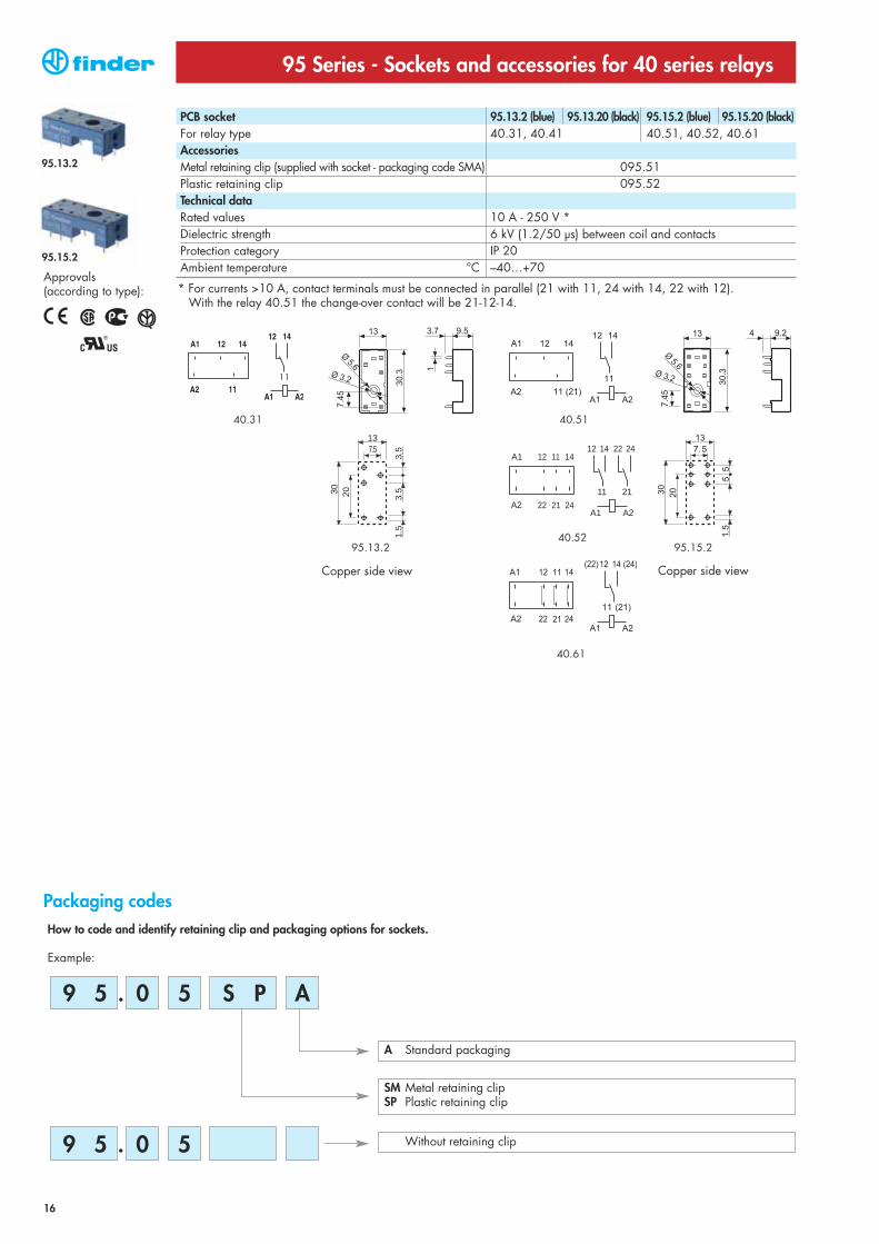
40.51
40.52
40.61
40.31
95.13.2 95.15.2
How to code and identify retaining clip and packaging options for sockets.
Example:
0 5.9 5
Packaging codes
A Standard packaging
Without retaining clip
SM Metal retaining clipSP Plastic retaining clip
S P A
0 5.9 5
Approvals (according to type):
PCB socket 95.13.2 (blue) 95.13.20 (black) 95.15.2 (blue) 95.15.20 (black)For relay type 40.31, 40.41 40.51, 40.52, 40.61AccessoriesMetal retaining clip (supplied with socket - packaging code SMA) 095.51Plastic retaining clip 095.52Technical dataRated values 10 A - 250 V *Dielectric strength 6 kV (1.2/50 µs) between coil and contacts Protection category IP 20Ambient temperature °C –40…+70
Copper side view
95 Series - Sockets and accessories for 40 series relays
Copper side view
* For currents >10 A, contact terminals must be connected in parallel (21 with 11, 24 with 14, 22 with 12).With the relay 40.51 the change-over contact will be 21-12-14.
16
95.15.2
95.13.2