finishing and polishing of a poly(fluoroalkoxy- phosphazene
TRANSCRIPT

Finishing and Polishing ofa Poly(fluoroalkoxy-
phosphazene) ResilientDenture Liner
fio6er( W. Loney. DMD, MS*
M. Brent Moulding, DMD, MS"
Corrine H. Hacker, DMD, MS***
College of DentistryUniversity of Saskatchewan
Ron G. Ritsco, DMD""University of Texas Health Science Center
A raised ridge of Novus resilient denture liner was removed from samplesusing one of three burs, three stones, or a coarse sandpaper disc. Sampleswere polished using pumice alone, tin oxide alone, or both agents. A flat,unfinished sample served as a control. Average surface roughness of controlsamples was 0.96 um. Average surface roughness measurements for reducedsamples ranged from 7,21 |im (sandpaper disc) to 3.34 jim (Prolastic wheeî).Without polishing, sandpaper discs and serrated burs produced roughersurfaces than stones or the nonserrated bur. The sandpaper disc reduced theliner the quickest. There were no significant differences between treatmentsor controls after the use of pumice aione or after the use of a combination ofpumice and tin oxide. An acceptabie finishing protocol for thispoiylfluoroalkoxyphosphazene) resilient iiner appears to differ from thatpreviously established for a silicone resilient denture liner. IntJ Prosfhodont1994;7:362-367.
T he adjustment and finishing of resilient dentureliners is difficult because of their resilience.' '
One study has established an acceptable finisbingprotocol for a poly(dimethyl siioxane), Molloplast-B.' It is conceivable that liners of different com-position or liners with different physical propertiescould require different finishing and polishingsequences. The purpose of the present study wasto determine an acceptable finishing protocol forthe poly(fluoroalkoxyphosphazene) resilient linerNovus (Hygenic, Akron, OH).
Methods and Materials
The Novus material was processed according tomanufacturer's instructions against 3 x 3-cm, heat-
*Associate Professor. Director, Division of tiemovabieProsthodontics.
"Associate Professor, Head. Department of Restorative andProsthetic Dentistry.
"'Assistant Professor, Division of Removable Prosthodontirs.""Graduate Student. Department of Graduate Prosthodontics.
Reprint requests: Or R.W. Loney, Dental Clinic. University ofSaskatchewan, Saskatoon, Saskatchewan. Canada 57N C)WO.
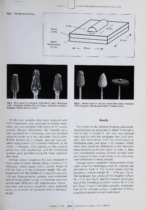
polymerized, denlure acryl ic resin samples{Lucitone 199, LD Caulk, Mi l fo rd , DE). Theresilient liner was processed as a flat surface, 2mm thick, except for a raised 5 x 15-mm half-cylindric ridge (Eig 1). Control samples wereprocessed without the raised ridge. Thirty-twoexperimental and four control samples wereprocessed. Eight techniques were each used toreduce the ridge on a group of four samples.Eigure 2 shows the three burs that were used: aMolloplast cutter (Mplst Ct) (Buffalo Dental,Brooklyn, NY); a Brasseler crosscut H79SG-070(C-Cutter) (Brasseler Canada, Montreal, PQ,Canada); and a Brasseler H351E-O6O (E-Cutter).The three stones (Eig 3] used were: a ProlasticIrimming wheel [Priste Wh) (Young Dental, StLouis, MO¡; Brasseler 747-140 (Green); and aMollobrasive stone (Mplst St) (Buffalo Dental).Addilionally, four samples were reduced wilh acoarse game! 5/8-inch sandpaper disc (Sandppr)(EC Moore, Dearborn, Ml) and four were reducedusing the Molloplast cutter together with theMollobrasive stone. The time required to reducethe ridge flush with the surrounding surface wasrecorded for each sample.
The Inlemational Journal ol Proslhodonlii 362 Í 7, Number 4, 1994
Loney et ai Poiyllluoroaikmj-pliosphazene) Resilient Denlure Liner
Fig 1 Sampie dimensions
Fig 2 Burs used for reduction (from Iett to right): Molloplastcutter, Brasseler H79SG-070 (G-Cutter], Brasseler crosscut,Brasseier H351E-060 (E-cutter).
Fig 3 Stones used for reduction (from left to right]; Brasseier747140 (green), Uoliobrasive stone, Prolastic wheel.
Of the four samples that were reduced witheach instrument, one received no further treat-ment, one was polished with slurry of 1/2 coarsepumice (Dento, Edmonton, AB, Canada] on awet rag wheel for 1,5 minutes, one was polishedusing tin oxide on a dry rag wheel (Acri-Lustre,Buffalo Dental] for 1 minute, and one was pol-ished using pumice (1,5 minutes] followed by tinoxide (1 minute). One sample of the controlgroup was left unpolished, and the remainingsamples were polished using the three regimensdescribed.
Average surface roughness (R=] was measured inthree areas of each sample using a Surftest-211(Mitutoyo, Tokyo, |apan] with a sample length of0.8 mm from a 4 mm evaluation length. The cali-brated error for the Surftest-2n was 0.02 jam over3,00 (im. Representative samples were examinedand photographed using a scanning electronmicroscope (SEM] at x 60 magnification. Reduc-tion time and surface roughness were analyzedusing an analysis of variance with a factorialdesign.
Results
The results for the different finishing and polish-ing techniques arc presented in Tables 1 through 5and in Figs 4 through 9, The liner was reducedmost quickly with the sandpaper disc (0,63 min-utes] and most slowly with the combination ofMolloplast cutter and stone (1,35 minutes]. Whilethere were significant differences in the reductiontimes between instruments listed in Table 2, therewas considerable overlap. Control samples werenot included in time comparisons, as no reductionswere performed on these samples.
Average surface roughness measurements of theeight reduction techniques and the controls areprovided in Table 4, The control sample had thesmoothest surface overall (R,i = 0,96 (im. Fig 4),The sandpaper disc produced the roughest surface(R,, = 7.21 (im. Fig 5], and the Prolastic wheel pro-duced the smoothest prepared surface (R,, = 3,34nm. Fig 6). Figure 7 provides a graphic representa-tion of the average surface roughness of theseunpolished samples for each instrument.
7, Number 4, 1994 363 The I mem a tion ai Journal of Proitiiodontics

PülylFiuoroalkoxyphospliazene) Resilienl Demure Lir
Fig 4 Ccntrol sample, (SEM K 60,) Fig 5 Unpolistieä sandpaper discsample, (SEM X 60 )
Fig 6 Unpolished Prclastic wheelsample, (SEM x 60,)
8
7
6
5
3
2
1
\
-O- Pumice-B" Pumice+Tin oxide-¿y Tin Oxide- • - Urpolishsd
Sandppr G-Cutter Uolpst C+S E-Cutter ControlMoloplst Ct Green Moloplst St Prolstc Wh
Instrument
Fig 7 Average surface rough-ness as a function of instrumentand polishing technique.
Average sudace roughness for eacb of the tbreepolishing techniques is listed, by reduction tech-nique in Table 5, When tin oxide was used alone,surfaces of some samples remained rougher thanthe control at the 95% level of confidence(Molloplast Cutter, 3.95 |im; E-Cutter, 3-43 fim;and Molloplast Stone, 2,61 \im). When pumice
Table 1 Analysis of Variance Summary Table forReduction Time
Sum ofsquares
Meansquare
Between groupsWithin groups
1,1750,598
0.1680.025
Tlie Interna liona 364 Volume 7, Number 4, 1994

PoivlMuoroaikoivpliosphazeíie) (íesilietii Denture Liner
Fig e (Left) Molloplast cutter andMollobrasive stone sample polishedwith pumice. (SEM x 60.)
Fig 9 (Right) G-Cutter bur-reducedsample polished with pumice and tinoxide. [SEM ^ 60.)
Table 2 Time Required to Reduce Ridge (min)
Technique Mean (SD) Groups'
Mlplst C+SMlpist CutterG-CutterSerratedMipist StPreiste WhGreenSandppr
Average
1.351.191.131.111.061.021.010.63
(0.11)(0.10)(0.09)(0.04)(0.09)(0.31)(0.05)(0.25)
1.063 (0.13)
'No differences within groups at the 95% leSchaffe F lest.
ei of confidence using the
Table 3 Analysis of Variance Summary Table forAverage Surface Roughness (Ra) afterReduction/Polish
Source
Between groupsWithin groups
Total
df
3572
107
Sum ofsquares
248.676.33
255.00
Meansquare
7.110.09
F test
80.82P < .0001
Table 4 Average Surface Roughness (Ra) otReduced Samples (ixm)
Technique Mean (SD) Groups'
SandpaperMlplst CtG-CutterGreenMlplst C+SMlplst StE-cutterProistc WhControi
Average
7.215.705.624.604.234.023.893.340.96
4,40
(0.65)(0.63)¡0.48)(0.42)(0.09)(0.48)(0.43)(0.74)(0.09)
(0.45)
"No differences wittiir groups at the 95% level ol confiOence using theScheffe F test.
Table 5 Average Surface Roughness (RJ of Polished Samples (^m)
Polish method
Pumice+Tin Oxide
Technique Mean (SD) Grcups' Mean (SD) Groups' Mean (SD) Groups'
Mlplst CtE-cutterMlplst StProistc WhSandpaperGreenMlplst C-FSG-CutterControl
Average
3.95 (0.34)3.43 (0.30)2.61 (0.19)2.33 (0.22)2.30 (0.15)1.95 (0.15)1.90 (0.16)1.82 (0.41)1.27 (0.21)
2.40 (0.24)
1.29 (0.10)1.98 (0.07)1.47 (0.28)1.48 (0.27)1.43 (0.14)1.58 (0.40)1.70 (0.03)1.21 (0.13)1.02 (0.07)
1.46 (0.17)
1.42 (0.05)1.57 (0.37)1.21 (0.11)1.59 (0.32)1.39 (0.29)1.59 (0.30)1.89 (012)1.44 (0.11)1.15 (0.33)
1.45 (0.22)
•No differences within groups at the 95% ievel of confidence using the Schaffe F test.
: 7, Number 4, 1994 365 The International lourriai ol iir

Loney et al
alone or a combinalion of pumice and tin oxidewere used, ¡here were no samples Ihal remainedrougher than the control at the 957o level of confi-dence. The effect of polishing on sample roughnessis shown in Fig 7 for each instrument tested.Scanning electron micrographs of samples pol-ished with pumice alone or with a combination ofpumice and tin oxide are shown in Figs 8 and 9,respectively.
Discussion
There was a clinical impression that the poly-(fluoroalkoxyphospliazene) resilient liner waseasier to adjust than the silicone liner that wasstudied previously.-' This subjective finding waspartially validated by the fact that reduction timesshowed minimal variation for any of the instru-ments used. Although there were statistical differ-ences between the reduction times, there was arange of only 0.72 minutes between the fastest andthe slowest times for instruments (compared to6.91 minutes for Molloplast-B as found in a previ-ous study'). While the sandpaper disc reduced theridge the quickest (0.63 minute), it also producedthe roughest surface (7.21 jiml. Average surfaceroughness values of unpolished samples were alsoclosely grouped, with a spread of 6.25 tm be-tween the smoothest and roughest surfaces (com-pared to 15.35 )jm for Molloplast-B as foundpreviousVl-
No clear differentiation could be made betweenthe efficacy of burs and stones in the present study.This is contrary to the findings relating to a siliconeliner, where burs were uniformly found to producethe roughest surfaces.' In the present study, onebur, the Brasseler E-Cutter (H351E-060), producedsamples that were among the smoothest (3.89 nm].This bur had not been used in a previous investiga-tion since it was relatively ineffective in reducingthe silicone liner during pilot testing. Clearly thereare differences in how these Ewo materials shouldbe adjusted, and findings from these two studiesshould not be extrapolated to other resilient linerswith different physical properties.
Polishing with tin oxide alone produced a finishthat differed statistically from the control samplesfor at least three of the instruments tested. Again,this finding differs from that for the silicone linerstudied previously. The poly {fluoroalkoxyphos-phazenej liner should be polished with eitherpumice alone or the combination of pumice andtin oxide. Since there were no differences betweensamples polished with pumice alone and thosepolished with both pumice and tin oxide, clini-
cians could save time polishing by using pumicealone.
Based on the results of this study, a recom-mended finishing and polishing regime for Novuswould include:
1. For initial reduction; Prolastic Wheel, BrasselerE-Cutter (H351 E-060) (previously recommendedfor use with Molloplast-B'l, Mollobrasive stonewith or without the Molloplast cutter, orBrasseler 747-140 "green" stone (previously rec-ommended for use with Molloplast-B'')
2. For polishing: pumice on a wet rag wheel
Samples polished by pumice alone or a combi-nation of pumice and tin oxide produced a smoothsurface that did not differ from that of the controlsregardless of the instrument used for initial reduc-tion. As such, the selection of a reduction instru-ment could be based on access to the area requir-ing adjustment, as long as adequate polishing ispossible. Several of the burs and stones testedcome in different sizes and shapes that would hemore suited to areas of limited access.
The present study simulates adjustments made inareas entirely bounded by the resilient liner. Oneaspect that has not been addressed is finishing ofthe resilient liner-acrylic resin junction. Differentinstrumentation may be optimal at the interface,where the resilient liner must be removed withoutditching the harder acrylic resin. The finishingof the resin-liner interface wil l be addressed infollow-up studies.
Conclusions
Considering the limitations of the study, the fol-lowing conclusions can be made:
1. Four of the instruments that were tested pro-duced significantly smoother surfaces than theother techniques at the 95% level of confi-dence. These were the Prolastic Wheel,Brasseler E-Cutter (H351 E-060), Mollobrasivestone with or without the Molloplast cutter, andthe Brasseler 747-140 green stone.
2. There were no significant differences in averagesurface roughness after samples were polishedwith either pumice alone or a combination ofpumice and tin oxide at the 95% leve! ofconfidence.
Acknowledgments
This study was supported by MRC Grant MD-3489.
The I me m ali ma I lournal of Prosthodonliti 366 Voliiine?, Number 4, 1994

Loney el al B) Resilient Denture Li
References
Laney WR. Processed resilient denture liners. Dent ClinN Am l970;14:53l-55!,Gonzalez JB, Laney WR. Resilient rraterials for dentureprostheses. I Prosthet Dent 19bb;16;438-444.
Schmidt W, Smith DE. A six-year retrospective study otMolloplast-B-lined dentures. Part II: Liner serviceability. JProsthet Dent 1 9!!3;5O:459-465.Loney RW, Moulding MB. The effect of finisliinR and pol-ishing on surface roughness of a processed resilient den-ture liner. ln t | ProsthodonL 1993;6:390-396.
Literature Abstracts -
The Effect of Incisai Bite Force on Condylar Seating
. ^ ^ - ^ — , ^ . ^ — ^ ^ ^ . . ,^1 lui 1 J ^^i^iii-pi M L. ^ 1.1 n i u . I U3< ii_3%_cin_i r I ma <.4CiP 1 11311 úL^U IJIC Uk/35l"^l 11L V U I UJII I t Lift
patient's masticatory musculature, through the generation of increased biting force, lo seat the condyie in thisdesired position. The purpose of (he present investigation was to study relationship between incisai biting forceand condylar seating. Kinematic transverse horizontal ayis locations were performed on 22 dental students (16men, 6 women) with intact anlerior dentitions and no temporomandibular joint symptoms. An occlusion-force
sure rorce; |Jt /.3 Kg closure lorce, ano 14) tne pauem s maximum closure torce. A line corresponding to tneaxis-ortiital plane was transferred to the preauricular flags for use as a reference. A traveling microscope wasused to compare recorded styli posiiions to this reference. Results demonstrated significanlly greater condylarseating, in an anterior and superior direction, as biting force increased. Authors suggest that increased diag-nostic and restorative information can be gained through the use of a technique that implements maximum bit-ing force, using a hardened anterior stop, for the recording of cenlric relation.
Woml DP, FloreaniKI, GaliiKA,TeteruckWB. AngleOrthod^9'i4,fl4.51-b2 References; 27. Reprinls; David P Wood, DDS,The University of Western Oniario, Demal Sciences Building, London, Oniario, Canada N3A 5CÍ .—David R. Cagna, DMD,The University of Texas Health Science Center al San Amonio. Sai Antonio, Texas.
Deformation ofthe Human Mandible During Simulated Tooth Clenching
F st research has identified mediolatersi dental arch deflections ranging from 0.03 to 0.78 mm, at the posteriortooth level. These studies involve non-occlusal mandibular positions to avoid influence of periodontal andalveolar tissue deformations on mandibular distortion. Tlie present study used a three-dimensional finite ele-ment model of the human mandible to assess deformation of the lower border of the mandible during simulat-ed static occlusal tasks. The established finite element modei included Ibe human mandible, leelh, periodontalligaments, laminae dura, and structures of the temporomandibular joints. The model was subjected to five stat-ic biting tasks in the following occlusal positions: (1) maximum inlercuspation; 12) left group function; 131 leftgroup function with cross-arch contact on the second molar; (4) incisai function; and (5) right molar contactonly. The model was loaded through multiple force vectors simulating masticatory muscle pull over a widearea of attachment lo tbe mandible. Results suggest that rotational distortions at Ihe rami, as the result ofmasticatory muscle pull, are manifested in the dental arch and condyles. Deformation during static functionwas with in the elastic range of the materials studied. The authors suggest that the identified rotational defor-mation may have a significant impact on prostheses place in the mandibular arch, especially those involvingimplants interconnected by rigid superstructures. Cyclic mandibular deformation could induce complex bend-ing of the prostbeses resulting in adverse effects on its elements,
KoriothTWP, Hannam AC. f Dent Res 1994;7:56-66. Referent«; 4S. Reprints; T,W.P. Koriolh, Department of Oral ScienceMinnesota Dental Research Center for Biomalerials and Biomechanics, School üf Deniisiry, Universily of MinresQta, 16-212Moos Tower, 515 Delaware 5treet SE. Minneapolis, Minnesota 5S455.—David R. Csgna. DMD. Ihe University of Texas He¡i¡thScience Center 3t San An!on¡o. San Arilortio. Texas.
Í 7, Number 4, 1994 3 6 7 The Iniernslional lournal ol Prosihodontii