finite element analysis of beam-column bolted end-plate ... · pdf filebuletinul institutului...
TRANSCRIPT

BULETINUL INSTITUTULUI POLITEHNIC DIN IAŞI Publicat de
Universitatea Tehnică „Gheorghe Asachi” din Iaşi Tomul LIX (LXIII), Fasc. 4, 2013
Secţia CONSTRUCŢII. ARHITECTURĂ
FINITE ELEMENT ANALYSIS OF BEAM-COLUMN BOLTED END-PLATE CONNECTIONS IN STEEL FRAMES
BY
SEBASTIAN-LUCIAN BUZULEAC*
Technical University of Civil Engineering Bucharest
Received: September 12, 2013 Accepted for publication: September 25, 2013
Abstract. In order to investigate the characteristics of beam-column bolted
end-plate connections in steel frames, ANSYS, a large-scale general-purpose finite-element package is selected to analyse several end-plate connections with various types and details. From the finite element analysis (FEA), the interaction between the end-plate and column flange, as well as geometric and material nonlinearities have been considered. Based on the results of FEA, the loading resistance and rotational stiffness of these connections and the tension forces distribution of the bolts have been presented, and the influences of connection details on the connection behavior have been discussed.
Key words: end-plate connection; finite element analysis; steel frame.
1. Introduction
Bolted connections, especially end-plate types, are being widely used in
steel structures. They are often used as moment-resistant connections. They have the advantages of easy quality control and less assembly time than welded connections. These connections include two types: flush end-plate connections and extended end-plate connections with or without stiffeners.
Conventional methods of steel frame analysis use two idealized connection models: either the rigid-joint model or the pinned-joint model. *e-mail: [email protected]

118 Sebastian-Lucian Buzuleac
Because the actual behavior of frame connections always falls in between these two extremes, much attention has been focused in recent years toward a more accurate modeling of such connections (Chen, 2000). So the moment-rotation (M – φ) behavior of connections have been studied deeply, which is necessary if the effects of connections are to be considered in structural analysis. Many tests of beam-column connections have been performed (Nethercot, 1985). But the practical connection types and sizes are numerous, especially the bolted end-pl ate connection, because of its innate characteristics of geometry details and assembly technology, it has many variable parameters, for example: bolt diameter, number of bolt rows and columns, vertical and horizontal bolt spacing, bolt grade, end-plate thickness, extension of end-plate beyond and below beam flange, end-plate width, end-plate stiffener, column stiffener, dimensions of beams and columns, bolt pretension force, yield strength of steel, slip coefficient of contact surfaces between end-plates, etc, so it is al most impossible to study its M – φ behavior only by tests.
In recent years, large-scale general-purpose finite element codes have developed rapidly and their functions are more and more perfect. This makes it possible to apply finite element analysis (FEA) on different bolted end-plate connections. Sherbourne & Bahaari (1994) used ANSYS 4.4 for FEA of end-plate connections, in addition to the overall behavior of the connection, the contribution of bolts, end-plate and column flange flexibility to the connection rotation was singled out, and the distribution and variation of prying forces was shown. They also used ANSYS 4.4 for FEA on 34 stiffened extended end-plate connections and 19 end-plate connections without stiffener in tension region, and then they gave a single standardized M – φ function for each of these two connection types by curve fitting (Sherbourne & Bahaari, 1997; Bahaari & Sherbourne, 1997). But their results are comparable only with two-way internal connections, and the version of ANSYS used is low.
Now the higher version of ANSYS provides many new functions that can simulate, analyse and compute the mechanical behavior of bolted end-plate connections more accurately. In this paper, 6 beam-column bolted end-plate connections with various types and details are simulated and analyzed by using new version of ANSYS.
Many new functions of this finite-element software are used to simulate each component of the connections more accurately. These connections are all originated from familiar multi-story steel frames. During the FEA, the interaction between the end-plate and column flange, as well as geometric and material nonlinearities have been considered, and the pretension force of bolts are not applied by initial strains of the conventional method but a new and more appropriate method. Based on the results of FEA, the loading resistance, rotational stiffness and M – φ relationship of these connections, the tension force distribution of the bolts and the contribution of components to joint

Bul. Inst. Polit. Iaşi, t. LIX (LXIII), f. 4, 2013 119
rotation have been presented, and the influences of connection details on the connection behavior have been discussed.
2. Finite Element Model
2.1. Geometric Details of Connections
The dimensions of columns and beams of these 8 connections are the same, shown in Table 1. A typical connection prototype model is shown in Fig. 1. Details of connections are shown in Fig. 2.
Table 1
Sectional Dimension of Beam and Column (unit: mm) Overall depth Web thickness Flange width Flange thickness
Beam 300 8 200 12 Column 300 8 250 12
Fig. 1 – A typical connection model. Fig. 2 – Details of connections.
The types and details of these 6 connections are shown in Table 2. The bolts are all high strength slip-critical bolts (Grade 10.9S). The thickness of the column flange is same as the end-plate thickness between 100 mm above and below the extension edge of the end-plate.

120 Sebastian-Lucian Buzuleac
Table 2 Types and Details of these 6 Connections
Case number
Connection type
End-plate
thickness mm
Bolt diameter
mm
Number of bolts
Bolt pretension
force KN
Column stiffener
End-plate
stiffener
SC1 flush 20 20 6 155 Yes – SC2 Extended 20 20 8 155 Yes Yes SC3 extended 20 20 8 155 Yes No SC4 extended 20 20 8 155 No Yes SC5 extended 25 20 8 155 Yes Yes SC6 extended 20 24 8 225 Yes Yes
2.2. Finite Element Model
The new version of large-scale general-purpose finite element software
ANSYS is used for the analysis and calculation of these connections. In the finite element models, all components of beams, columns and
end-plates are meshed by 10-node tetrahedral structural solid element SOLID92; the interface between the end-plate and the column flange is simulated by creating contact pairs with 3-D target surface elements TARGE170 and 3-D 8-node surface-to-surface contact elements CONTAC174.
High strength slip-critical bolts are also meshed by 10-node tetrahedral structural solid element SOLID92. The PSMESH command is used to define the pretension sections in the middle of the bolt shanks and generate the pretension elements PRETS17 9 through which the pretension force of the bolts are applied by using the command SLOAD.
Fig. 3 – A typical finite element model of connections.
Due to the geometric symmetry of all the connections about a plane pa
ssing through the beam and column webs, only one half of all the connections
Bul. Inst. Polit. Iaşi, t. LIX (LXIII), f. 4, 2013 121
are modeled during FEA. A typical finite element model of connections is shown in Fig. 3.
2.3 Material Properties
In the finite element models, the adopted stress–strain relationships of
steel plates are elastic-perfectly plastic and the Poisson’s ratio is 0.3. Yield strength of steel plates thicker than 16 mm is 363 MPa and its elastic modulus is taken as 204,227 MPa, and yield strength of steel plates thinner than or equal to 16 mm is 391 MPa and its elastic modulus is taken as 190,707 MPa. The stress–strain relationship of high strength slip-critical bolts (including bolt heads, shanks and nuts) is trilinear, the stress vs. strain points data of the trilinear curve is shown in Table 3. The friction coefficient of contact surfaces between end-plate and column flange is 0.44. All the above data of material properties are obtained from tests (Shi et al., 2004).
Table 3. Material Properties of High Strength Bolts
Stress, [MPa] 990 1,160 1,160 Strain 0.00483 0.136 0.15
2.4. Analysis Program
During the analysis and solution of these finite element models,
displacement loads were applied on the loading point as shown in Fig. 1. Also the value of the displacement load of each connection is referred to the test data (Shi et al., 2004). The analysis type is “Large Displacement Static” which is second-order elasto-plastic analysis. The material yield criterion is von Mises yield criterion, and the flow rule is adopted after yielding.
3. Results of FEA and Discussion
3.1. Loading Capacity and Moment Resistance
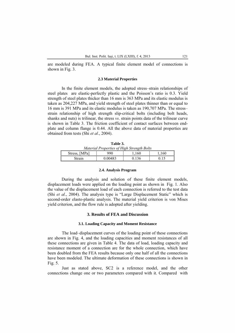
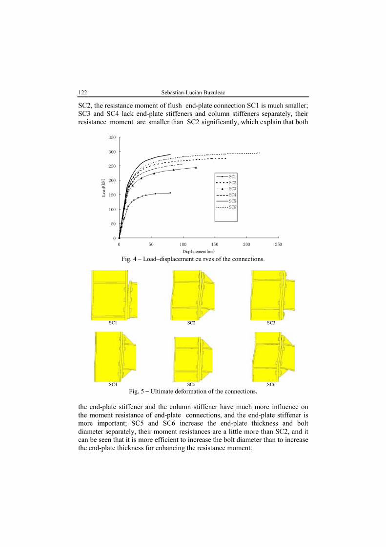
The load–displacement curves of the loading point of these connections are shown in Fig. 4, and the loading capacities and moment resistances of all these connections are given in Table 4. The data of load, loading capacity and resistance moment of a connection are for the whole connection, which have been doubled from the FEA results because only one half of all the connections have been modeled. The ultimate deformation of these connections is shown in Fig. 5.
Just as stated above, SC2 is a reference model, and the other connections change one or two parameters compared with it. Compared with
122 Sebastian-Lucian Buzuleac
SC2, the resistance moment of flush end-plate connection SC1 is much smaller; SC3 and SC4 lack end-plate stiffeners and column stiffeners separately, their resistance moment are smaller than SC2 significantly, which explain that both
Fig. 4 – Load–displacement cu rves of the connections.
Fig. 5 – Ultimate deformation of the connections.
the end-plate stiffener and the column stiffener have much more influence on the moment resistance of end-plate connections, and the end-plate stiffener is more important; SC5 and SC6 increase the end-plate thickness and bolt diameter separately, their moment resistances are a little more than SC2, and it can be seen that it is more efficient to increase the bolt diameter than to increase the end-plate thickness for enhancing the resistance moment.

Bul. Inst. Polit. Iaşi, t. LIX (LXIII), f. 4, 2013 123
3.2. Moment-Rotation Behavior
The conventional definition of joint rotation φ is done by the change of
the included angle between the axes of the beam and column that the joint connects under load. So, in this paper, the joint rotation, φ, of the beam-column end-plate connection is defined as the relative rotation of the center lines of the beam top and lower flanges at the beam end, and it usually includes two parts: φep , rotation caused by the relative deformation between the end-plate and the column flange, and φs , rotation caused by the shearing deformation of the panel zone of the column (Fig. 6). M – φ, M – φep and M – φs curves of these con-nections are shown in Fig. 7.
Fig. 6 – Load–displacement curves of the connections.
According to Eurocode 3(CEN, 1993), when a connection is classified
by rigidity, its secant rotational stiffness corresponding to the moment of 2/3 of the design plastic resistance moment of the beam is calculated and compared to the flexural stiffness of the beam EIb/Lb. The connection is rigid when the secant rotational stiffness is bigger than some specific value, which is 25EIb/Lb for unbraced frames, as defined by Eurocode 3. The connection is nominally pinned when the secant rotational stiffness is smaller than some specific value, which is defined as 0.5EIb/Lb in Eurocode 3. Between these two values, the connection is semirigid.
Because the same section of the beams of the finite element models is often used in steel frames with the typical span as long as 5 m, the length of the

124 Sebastian-Lucian Buzuleac
beam, Lb , is 5 m, in this paper. So the flexural stiffness of the beam EIb/Lb is 4,333 kN.m (E = 190,707 MPa). Because the design strength value of the steel plates of the beams is 310 MPa, the design plastic moment resistance of the beam is 261.5 kN.m, 2/3 of which is 177.3 kN.m. The secant rotational stiffness corresponding to 177.3 kN.m of all these connections is given in Table 4. In Fig. 7, the boundary curve represents the boundary between the rigid and semirigid connection for unbraced frames calculated from Eurocode 3 (CEN,
Fig. 7 – M – φ, M – φep and M – φs curves of the connections.
1993), and if the rising portion of M – φ curve of a connection lies above the boundary curve, it can be considered to be rigid, otherwise it is semirigid. From
Bul. Inst. Polit. Iaşi, t. LIX (LXIII), f. 4, 2013 125
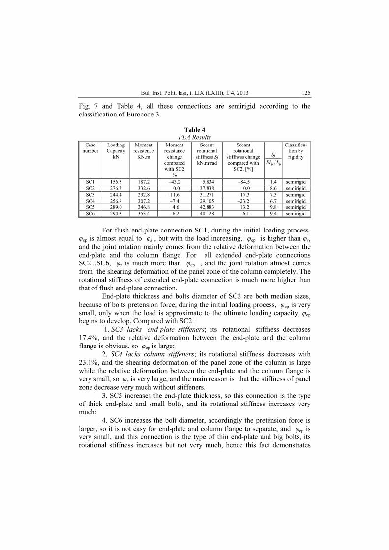
Fig. 7 and Table 4, all these connections are semirigid according to the classification of Eurocode 3.
Table 4
FEA Results Case
number Loading Capacity
kN
Moment resistence
KN.m
Moment resistance
change compared with SC2
%
Secant rotational
stiffness Sj kN.m/rad
Secant rotational
stiffness change compared with
SC2, [%]
b b
SjEI L
Classifica-tion by rigidity
SC1 156.5 187.2 –43.2 5,834 –84.5 1.4 semirigid SC2 276.3 332.6 0.0 37,838 0.0 8.6 semirigid SC3 244.4 292.8 –11.6 31,271 –17.3 7.3 semirigid SC4 256.8 307.2 –7.4 29,105 –23.2 6.7 semirigid SC5 289.0 346.8 4.6 42,883 13.2 9.8 semirigid SC6 294.3 353.4 6.2 40,128 6.1 9.4 semirigid
For flush end-plate connection SC1, during the initial loading process,
φep is almost equal to φs , but with the load increasing, φep is higher than φs, and the joint rotation mainly comes from the relative deformation between the end-plate and the column flange. For all extended end-plate connections SC2...SC6, φs is much more than φep , and the joint rotation almost comes from the shearing deformation of the panel zone of the column completely. The rotational stiffness of extended end-plate connection is much more higher than that of flush end-plate connection.
End-plate thickness and bolts diameter of SC2 are both median sizes, because of bolts pretension force, during the initial loading process, φep is very small, only when the load is approximate to the ultimate loading capacity, φep begins to develop. Compared with SC2:
1. SC3 lacks end-plate stiffeners; its rotational stiffness decreases 17.4%, and the relative deformation between the end-plate and the column flange is obvious, so φep is large;
2. SC4 lacks column stiffeners; its rotational stiffness decreases with 23.1%, and the shearing deformation of the panel zone of the column is large while the relative deformation between the end-plate and the column flange is very small, so φs is very large, and the main reason is that the stiffness of panel zone decrease very much without stiffeners.
3. SC5 increases the end-plate thickness, so this connection is the type of thick end-plate and small bolts, and its rotational stiffness increases very much;
4. SC6 increases the bolt diameter, accordingly the pretension force is larger, so it is not easy for end-plate and column flange to separate, and φep is very small, and this connection is the type of thin end-plate and big bolts, its rotational stiffness increases but not very much, hence this fact demonstrates

126 Sebastian-Lucian Buzuleac
that the end-plate thickness influences the joint stiffness more significantly than bolt diameter.
3.3. Bolt Tension Force Distribution
Curves of bolt tension force vs. moment of these connections are shown
in Fig. 8, in which the first, second, third and fourth bolt-row is sequential from the tension side to the compression side of the beam. And the bolt tension force distribution is shown in Fig. 9, in which curve 1, 2 and 3 indicate the initial stage (elastic stage), the intermediate stage and, respectively, the ultimate stage
Fig. 8 – Bolt tension force-moment curves.
of loading, the loads of which are given in Table 5. The loads of curves 1, 2 and 3 of each connection are approximately equal to 1/3, 2/3 and, respectively,

Bul. Inst. Polit. Iaşi, t. LIX (LXIII), f. 4, 2013 127
the total of the loading capacity of each connection. In Figs. 8 and 9, for SC6 and SC7, if the bolt-row tension force is larger than 225 kN (the pretension force), the bolt is in tension zone , and vice versa; for the others, if the bolt-row tension force is larger than 155 kN (the pretension force), the bolt is situated in tension zone, and vice versa.
Fig. 9 – Bolt tension force distribution.
From Figs. 8 and 9, it can be seen that: 1. For flush end-plate connection SC1, the tension force of the first
bolt-row (the first bolt-row in the inner side of beam tension flange) is maximal all along. Only when the load is approximated to the ultimate loading capacity, the tension force of the second bolt-row begins to develop, and a small tension force occurs in the third bolt-row at this time, the rotation center of the connection is generally on the centerline of the beam compression flange which is below the third bolt-row.

128 Sebastian-Lucian Buzuleac
Table 5
Load and Moment Values of Curve 1, 2 and 3 of the Connections Case number Curve 1 Curve 2 Curve 3
SC1 38.8 (46.6) 98.8 (118.6) 156.2 (187.4) SC2 108.1 (129.6) 185.7 (222.8) 276.2 (331.6) SC3 78.3 (93.8) 147.5 (177.0) 244.6 (293.3) SC4 97.1 (116.6) 172.5 (207.2) 256.2 (307.2) SC5 91.8 (110.3) 190.3 (228.3) 289.0 (346.8) SC6 88.6 (106.3) 212.3 (254.8) 294.5 (353.3)
* In this table, the value outside the bracket is load (unit: kN), and the value in the bracket is the corresponding moment (unit: kN.m).
2. For SC2 and SC4...SC6, extended end-plate connections with end-
plate stiffeners and column stiffeners, the tension force of the first bolt-row is maximal all along, and the tension force of the second bolt-row develops gradually. The rotation center of the connection is generally on the centerline of the beam compression flange.
3. For SC3, extended end-plate connection with column stiffeners and without end-plate stiffeners, the tension force of the first bolt-row is almost equal to that of the second bolt-row all over the loading process.
5. Conclusions 1. FEA can simulate, analyse and compute the mechanical behavior of
bolted end-plate connections appropriately. 2. An explicit definition of the joint rotation of the beam-column bolted
end-plate connection has been proposed. 3. In many cases, end-plate connections are semirigid connections, and
the influences of joint stiffness on the behavior of the frame should be considered. Its detailed rotational behavior and design method are to be studied further.
4. For flush end-plate connections, the joint rotation mainly comes from the relative deformation between the end-plate and the column flange. For extended end-plate connections, the joint rotation almost comes from the shearing deformation of the panel zone of the column completely.
5. The column stiffener and the end-plate stiffener influence the joint rotation stiffness very much. If it is necessary to increase the joint rotation stiffness, the type of extended end-plate connections with column stiffeners and end-plate stiffeners is preferable. The end-plate thickness influences the joint stiffness more than bolt diameter.

Bul. Inst. Polit. Iaşi, t. LIX (LXIII), f. 4, 2013 129
REFERENCES
Bahaari M. R., Sherbourne A. N., Finite Element Prediction of End Plate Bolted
Connection Behavior. II: Analytic Formulation. J. of Struct. Engng., 123, 2, 165-175 (1997).
Chen W.F., Practical Analysis for Semi-Rigid Frame Design. World Sci., Singapore, 2000.
Nethercot D.A., Steel Beam-to-Column Connections: A Review of Test Data and their Application to the Evaluation of Joint Behavior on the Performance of Steel Frames. CIRIA Proj. Record 338, London, 1985.
Sherbourne A.N., Bahaari M.R., 3-D Simulation of End-Plate Bolted Connections. J. of Struct. Engng., 120, 11, 3122-3136 (1994).
Sherbourne A.N., Bahaari M. R., Finite Element Prediction of End Plate Bolted Connection Behavior. I: Parametric Study. J. of Struct. Engng., 123, 2, 157-164 (1997).
Shi G., Shi Y.J., Wang Y.Q., Li S., Chen H., Experimental Study on Semirigid End-Plate Connections in Multi-Story Steel Frames. J. Tsinghua Univ. Sci. a. Techn. (2004).
* * * Design of Steel Structures: Part 1.1 General Rules and Rules for Buildings. CEN, Eurocode 3, 1993
ANALIZA CU ELEMENT FINIT A ÎMBINĂRILOR GRINDĂ-STÂLP PREVĂZUTĂ CU PLACĂ DE CAPĂT ŞI ŞURUBURI, DE LA UN CADRU METALIC
(Rezumat)
Pentru a investiga caracteristicile îmbinărilor cu şuruburi de tip grindă-stâlp cu
placă de capăt ale structurilor metalice, s-a ales programul de calcul ANSYS, pachetul element finit cu scop general de largă aplicabilitate, pentru a analiza mai multe îmbinări cu placă de capăt de diferite tipuri şi cu diverse detalii. În analiza elementului finit (FEA), au fost luate în considerare interacţiunea dintre placa de capăt şi flanşa stâlpului, precum şi nelinearităţile geometrice şi de material. Pe baza rezultatelor FEA (analizei elementului finit) au fost prezentate rezistenţa la sarcină şi rigiditatea la răsucire a acestor îmbinări, distribuţia eforturilor tensiunile în şuruburi şi au fost analizate influenţele elementelor ce intră într-o îmbinare, asupra comportamentului îmbinării.