finite element analysis of elastic stresses around … · finite element analysis of elastic...
TRANSCRIPT

Bonfring International Journal of Industrial Engineering and Management Science, Vol. 2, No. 4, December 2012 136
Finite Element Analysis of Elastic Stresses around Holes in Plate Subjected to Uniform Tensile
Loading B. Mallikarjun, P. Dinesh, K.I. Parashivamurthy
Abstract--- The author reported stress analysis of infinite isotropic plate with a cylindrical circular hole and oblique hole. The present work deals with infinite isotropic plate under uniform tensile load. Three components of different material with different obliquity angle were used for analysis. These components having holes circular & oblique at angles 0, 30 and 60 degree are considered for study. The long twisted blades of gas turbine blade will be treated as infinite plate with oblique holes/cooling holes constituting a geometrically complex, three- dimensional body that is subjected to the action of systems centrifugal force. Stress concentration and stress field around oblique holes is a major challenge area in design of aerofoil in aerospace applications for safety because of their highly specialized applications in aerospace field under severe operating conditions. In design, Stress Concentration Factor (SCF) can be used as multiplication factor, and using that maximum stress can be predicted, thus it shows the stress field around local region. The experimental methods used are photo elastic and strain gauge techniques. When a infinite plate containing a cylindrical oblique hole is subjected to remotely applied uniform tensile load, the circumferential stresses along the boundary of the hole are produced which have been successfully used to predict stresses around holes. The resulting Stress Concentration Factor (SCF) obtained by Finite Element (FE) analysis are compared with experimentally obtained values. The results of FEA technique are in good agreement with experimental values, thus providing a means of analysing more effectively realistic Gas turbine blades. For analysis FEA software MSC/PATRAN, MSC/ NASTRAN-NX v7.0 has been used.
Keywords--- Finite Element Method (FEM), Infinite Plate, Oblique Holes, SCF, Stress Analysis, Uniform Tensile load
I. INTRODUCTION The study of elastic stress field around discontinuous in
geometry is very important for researchers and designers for safe- life of the components. In this work hole is cylindrical
B. Mallikarjun, Asst. Prof., Dept of Mechanical Engineering-PG,
Nagarjuna College of Engineering & Technology, Devanahalli, Bangalore-562110.E-mail:[email protected]
P. Dinesh, Professor, Dept of Mechanical Engineering, MSRIT, Bangalore-54. E-mail:[email protected]
K.I. Parashivamurthy, Prof. & HOD, Dept of Mechanical Engineering, Govt. Engineering College, Chamarajanagar. E-mail:[email protected] DOI: 10.9756/BIJIEMS.1824
circular and oblique hole for infinite plate is considered for stress analysis and they are made up of homogenous, isotropic, and linear elastic material, the cause of this highly localized or accumulation of stress near the change of cross section or clustering of stress lines at the point of discontinuity is termed as stress concentration [1]. The principal cause of stress raisers like holes & notches, because concentrated stresses larger than theoretical cohesive strength will generally cause local plastic deformation and redistribution of stresses [2].
An oblique hole is one whose axis is not normal to the infinite plate which it penetrates. These holes can be found at non-radial openings in cylindrical and spherical shells, gas engine turbine blades [3, 4]. In any ideal, linear elastic component, the ratio of the maximum stress to the nominal stress (σMax/ (σMin) is designated as stress concentration factor (kt). The stress concentration factor solely depends on the geometry, mode of loading and type of material selected. Geometrical configuration of these holes can be circular, elliptical or it may be a square depending on design requirements [5]. The stress fields are of great interest for researchers, engineers, designers and academination for many years.
The stresses around holes can be determined for infinite plate by using theory of elasticity. In the case of oblique/skew holes, most of stress analysis has been carried out using photo elastic technique. At the intersection with a plane surface, a skewed cylindrical hole gives rise to an elliptical trace and produces an acute-angled edge which, for large angles of obliquity with respect to the normal [10]. Photo elastic investigation was carried out by the stress-frozen method to investigate stresses at oblique holes [6, 7]. Most of this work is based on assumptions of plane stress or plane strain and was accomplished by means of conformal mapping techniques widely used by Muskhelishvili. Comprehensive reviews on the subject have also been given by Neuber and Savin [8].The theoretical study of the elastic-stress field in a plate with a skew hole has been given by authors Ellyin, Lind, and Sherburne. Infinite plate with tension is restricted to small angles of skewness [6]. The classical solutions by Kirsch for the case of a single circular hole in an infinite plate, many other problems have been solved [9]. In this work oblique holes with various angles of inclination are used (0°, 30° and 60°). This approach is based on the concept that the gas turbine blade components are analysed for the stresses treating them like an infinite plate with holes.
ISSN 2277-5056 | © 2012 Bonfring
Bonfring International Journal of Industrial Engineering and Management Science, Vol. 2, No. 4, December 2012 137
1.1 Notations
Following symbols & notations were considered for infinite plate with oblique hole.
t Thickness of the infinite plate(mm) w Width of the infinite plate(mm) l Length of the infinite plate(mm) d Cylindrical hole diameter(mm)
θ Angular coordinate in plane normal to hole axis (degree) ⌀ Angle between major axis of elliptical intersection of
Hole in plane of plate and direction of applied uniaxial range 0-90° (degree)
α Oblique Angle between hole axis and plate normal range 0-90°
a Semi major axis of the ellipse(in the x-direction, in mm)
b Semi minor axis of the ellipse(in the y-direction, in mm) distances from hole to edge of plate and end of plate (mm)
dl Displacement(mm) P Remotely applied uniform tensile load (N)
D1, D2 Minimum E Young’s modulus(N/mm2) µ Poison’s Ratio ρ Density of material (Kg/mm3)
II. METHODOLOGY
2.1 Finite Element Method (FEM)
2.1.1 Models Analyzed The plate is considered as infinite plate so that width and
length of plate were such that the effects of the plate edges and boundary conditions on the hole stresses were negligible. As a result, infinite plate conditions were attained in the region of the hole (w/d=10 or greater then 10). The analysed model work covers a practical useful range of hole variables (α, ⌀, h/d). Here the component is considered to be infinite plate with the following equation:
10
w = width of the plate, mm,
d = diameter of the hole, mm
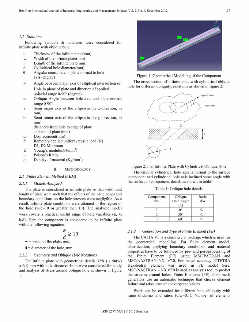
2.1.2 Geometry and Oblique Hole Notations The infinite plate with geometrical details 325(l) x 50(w)
x 6(t) mm with hole diameter 5mm were considered for study and analysis of stress around oblique hole as shown in figure 1.
Figure 1: Geometrical Modelling of the Component
The cross section of infinite plate with cylindrical oblique hole for different obliquity, notations as shown in figure 2.
Figure 2: Flat Infinite Plate with Cylindrical Oblique Hole
The circular cylindrical hole axis is normal to the surface component and cylindrical hole axis inclined some angle with the surface of component, details as shown in table1
Table 1: Oblique hole details
2.1.3 Generation and Type of Finite Element (FE) The CATIA V5 is a commercial package which is used for
the geometrical modelling. For finite element model, discritization, applying boundary conditions and material properties have to be followed by pre- and post-processing of the Finite Element (FE) using MSC/PATRAN and MSC/NASTRAN NX- v7.0. For better accuracy, CTETRA Hexahedral element was used in FE model here. MSC/NASTRAN – NX v7.0 is used as analysis tool to predict the stresses around holes. Finite Elements (FE), their mesh generators use an automatic technique that checks element failure and takes care of convergence values.
Work can be extended for different hole obliquity with same thickness and ratios (d/w=0.1). Number of elements
Component. No.
Oblique Hole Angle
(α)
Ratio d/w
1 0° 0.1 2 30° 0.1 3 60° 0.1
ISSN 2277-5056 | © 2012 Bonfring

Bonfring International Journal of Industrial Engineering and Management Science, Vol. 2, No. 4, December 2012 138
resulted from the automatic meshing of the MSC/PATRAN software package which minimized element distortion. Figure 3 shows a close-up view of the nodes around the hole, which are not uniformly distributed. To save computational time and cost, the meshes were refined in the critical area (around the oblique hole), where the stresses had a rapid variation until convergence was achieved. Larger elements were used elsewhere. None of the elements were excessively elongated or distorted. In this way the number of elements was optimized to give accuracy at a reasonable cost. The angles α and ⌀were important parameters in the number of elements required for the models. For more or high values of α and ⌀ the number of required elements was very high. The computational analysis was carried out using MSC/NASTRAN –NX v7.0.Finite Element (FE) model as shown in figure 3.
Figure 3: Typical Finite Element Mesh for Flat Infinite Plate
with Oblique Hole The Finite Element (FE) model details of infinite plate
used for analysis as given in table 2. CTETRA 2nd-order hexahedral element is preferred for more accuracy & properties.
Table 2: Finite Element (FE) Model Details
Finite element method is a powerful technique used for analysis of elastic stresses around cylindrical oblique hole. Here, a general method of Finite Element Analysis (FEA) is used. The results of stress contours for plain stress condition are obtained, and they are very in good agreement with experimental results. This ables us to predict the distribution of stresses around oblique hole.
2.1.4 Boundary Conditions Type of constrains & loading considered for stress
analysis of infinite plate with circular & oblique hole subjected to uniform tension load 1000N as shown in figure 4.
Figure 4: Boundary Conditions (Loading and Constraints)
2.1.5 Material & Properties Details Stress analysis is carried out for different materials. Linear
elastic stresses around hole for low carbon steel, Titanium, Nickel and their properties were considered for analysis around hole local region. The chemical composition of alloy steel as shown in table 3.
Table 3: Chemical Composition of Low Carbon Steel
For study & stress analysis following material properties
are considered as shown in table 4;
Table 4: Material Properties of alloy steel & super alloy
The FEA solver NASTRAN –NX v7.0 is used to solve the
pre-processor data file. There is a good correlation between the FEA and experimental results. The results are presented in figure 5; to figure 10; In post- processor result can be presented in the stress contours /tabular form.
Stress Concentration Factor (SCF) can be considered in design analysis while calculating stress field around local
Sl. No
Oblique Hole Angle
(Α)
Finite Elements
Elements
Sizing
No. of Nodes
No. of Elements
1 0 CTETRA 2nd-order
4 133218 29344
2 30 CTETRA 2nd-order
1 134218 29575
3 60 CTETRA 2nd-order
0.7 799745 181458
Composition Weight % C 0.562 Mn 0.446 Si 0.155 S 0.008 P 0.027 Cr 0.050 Ni <0.05 Mo <0.001
Material Name
Modulus of Elasticity
(E) N/mm2
Poisson’s Ratio (µ)
Density (ρ) Kg/mm3
Alloy steel (Low Carbon
Steel) 2 X 10⁵ 0.3 7.85 X 10⁻⁶
Super alloy (Nickel) 1.9 X 10⁵ 0.305 8.908 X 10⁻³
ISSN 2277-5056 | © 2012 Bonfring

Bonfring International Journal of Industrial Engineering and Management Science, Vol. 2, No. 4, December 2012 139
region. Three angles of inclination of the hole with respect to the surface of the plate, 0, 30 & 60 degrees will be considered for study & analysis.
III. RESULTS AND DISCUSSION
3.1 Finite Element Analysis (FEA) results The distribution of stresses/stress contours around holes
for different oblique angles subjected to remotely applied tensile and bending load as shown in figure 5 to 10.
Figure 5: Typical View of Stress Contour around 00 Normal Hole for Steel Infinite Plate
Figure 6: Typical View of Stress Contour around 300 Oblique Hole for Steel Infinite Plate
Figure 7: Typical View of Stress Contour around 600 Oblique Hole for Infinite Steel Plate
Figure 8: Typical View of Stress Contour around 00 Normal
Hole for Nickel Infinite Plate
Figure 9: Typical View of Stress Contour around 300 Oblique
Hole for Nickel Infinite Plate
Figure 10: Typical View of Stress Contour around 600 Normal Hole for Nickel Infinite Plate
The stress analysis around holes was obtained for different
obliquity and results are shown in table 5. The results are shown for different materials with oblique angles subjected to tensile load.
ISSN 2277-5056 | © 2012 Bonfring
Bonfring International Journal of Industrial Engineering and Management Science, Vol. 2, No. 4, December 2012 140
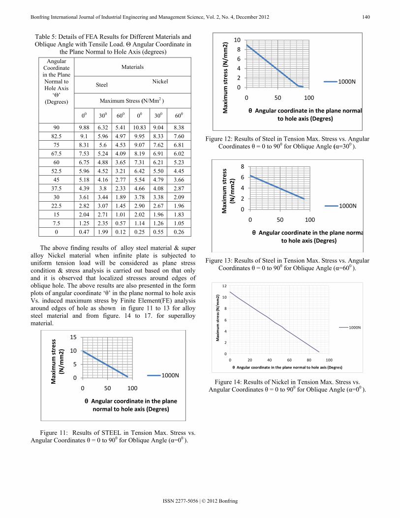
Table 5: Details of FEA Results for Different Materials and Oblique Angle with Tensile Load. Θ Angular Coordinate in
the Plane Normal to Hole Axis (degrees)
The above finding results of alloy steel material & super
alloy Nickel material when infinite plate is subjected to uniform tension load will be considered as plane stress condition & stress analysis is carried out based on that only and it is observed that localized stresses around edges of oblique hole. The above results are also presented in the form plots of angular coordinate ‘θ’ in the plane normal to hole axis Vs. induced maximum stress by Finite Element(FE) analysis around edges of hole as shown in figure 11 to 13 for alloy steel material and from figure. 14 to 17. for superalloy material.
Figure 11: Results of STEEL in Tension Max. Stress vs. Angular Coordinates θ = 0 to 900 for Oblique Angle (α=00 ).
Figure 12: Results of Steel in Tension Max. Stress vs. Angular
Coordinates θ = 0 to 900 for Oblique Angle (α=300 ).
Figure 13: Results of Steel in Tension Max. Stress vs. Angular
Coordinates θ = 0 to 900 for Oblique Angle (α=600 ).
Figure 14: Results of Nickel in Tension Max. Stress vs.
Angular Coordinates θ = 0 to 900 for Oblique Angle (α=00 ).
0
5
10
15
0 50 100
Maxim
um stress
(N/m
m2)
θ Angular coordinate in the plane normal to hole axis (Degres)
1000N
0
2
4
6
8
10
0 50 100
Maxim
um stress (N/m
m2)
θ Angular coordinate in the plane normal to hole axis (Degres)
1000N
0
2
4
6
8
0 50 100Maxim
um stress
(N/m
m2)
θ Angular coordinate in the plane normato hole axis (Degres)
1000N
0
2
4
6
8
10
12
0 20 40 60 80 100
θ Angular coordinate in the plane normal to hole axis (Degres)
Maxim
um stress (N/m
m2)
1000N
Angular Coordinate in the Plane Normal to Hole Axis
‘Θ’ (Degrees)
Materials
Steel Nickel
Maximum Stress (N/Mm2 )
00 300 600 00 300 600
90 9.88 6.32 5.41 10.83 9.04 8.38 82.5 9.1 5.96 4.97 9.95 8.33 7.60 75 8.31 5.6 4.53 9.07 7.62 6.81
67.5 7.53 5.24 4.09 8.19 6.91 6.02 60 6.75 4.88 3.65 7.31 6.21 5.23
52.5 5.96 4.52 3.21 6.42 5.50 4.45 45 5.18 4.16 2.77 5.54 4.79 3.66
37.5 4.39 3.8 2.33 4.66 4.08 2.87 30 3.61 3.44 1.89 3.78 3.38 2.09
22.5 2.82 3.07 1.45 2.90 2.67 1.96 15 2.04 2.71 1.01 2.02 1.96 1.83 7.5 1.25 2.35 0.57 1.14 1.26 1.05 0 0.47 1.99 0.12 0.25 0.55 0.26
ISSN 2277-5056 | © 2012 Bonfring
Bonfring International Journal of Industrial Engineering and Management Science, Vol. 2, No. 4, December 2012 141
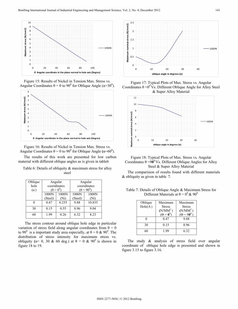
Figure 15: Results of Nickel in Tension Max. Stress vs.
Angular Coordinates θ = 0 to 900 for Oblique Angle (α=300).
Figure 16: Results of Nickel in Tension Max. Stress vs.
Angular Coordinates θ = 0 to 900 for Oblique Angle (α=600). The results of this work are presented for low carbon
material with different oblique angles as is given in table6
Table 6: Details of obliquity & maximum stress for alloy steel
The stress contour around oblique hole edge in particular variation of stress field along angular coordinates from θ = 0 to 900 is a important study area especially, at θ = 0 & 900. The distribution of stress intensity for maximum stress vs. obliquity (α= 0, 30 & 60 deg.) at θ = 0 & 900 is shown in figure 18 to 19.
Figure 17: Typical Plots of Max. Stress vs. Angular
Coordinates θ =00 Vs. Different Oblique Angle for Alloy Steel & Super Alloy Material
Figure 18: Typical Plots of Max. Stress vs. Angular Coordinates θ =900 Vs. Different Oblique Angles for Alloy
Steel & Super Alloy Material The comparision of results found with different materials
& obliquity as given in table 7.
Table 7: Details of Oblique Angle & Maximum Stress for Different Materials at θ = 00 & 900
The study & analysis of stress field over angular
coordinate of oblique hole edge is presented and shown in figure 3.15 to figure 3.16.
0
1
2
3
4
5
6
7
8
9
10
0 20 40 60 80 100
θ Angular coordinate in the plane normal to hole axis (Degres)
Maxim
um stress (N
/mm2)
1000N
0
1
2
3
4
5
6
7
8
9
0 20 40 60 80 100
θ Angular coordinate in the plane normal to hole axis (Degres)
Maximum
stress (N/m
m2)
1000N
0
0.5
1
1.5
2
2.5
0 10 20 30 40
oblique angle in degrees (α)
Maxim
um nom
inal stress (N/m
m2)
1000N
0
2
4
6
8
10
12
0 10 20 30 40
oblique angle in degrees (α)
Maxim
um nom
inal stress (N/m
m2)
1000N
Oblique hole (α )
Angular cooridinates
(θ = 00)
Angular cooridinates
(θ = 900) 1000N (Steel)
1000N (Ni)
1000N (Steel)
1000N (Ni)
0 0.47 0.255 9.88 10.835
30 0.15 0.55 8.96 9.04
60 1.99 0.26 6.32 8.23
Oblique Hole(Α )
Maximum Stress
(N/MM2 ) (Θ = 00)
Maximum Stress
(N/MM2 ) (Θ = 900 )
0 0.47 9.88
30 0.15 8.96
60 1.99 6.32
ISSN 2277-5056 | © 2012 Bonfring

Bonfring International Journal of Industrial Engineering and Management Science, Vol. 2, No. 4, December 2012 142
ISSN 2277-5056 | © 2012 Bonfring
in nickel material. In alloy steel maximum induced
lot from figure
IV. CONCLUSIONS Three aeros ls were studied
suc
REFERENCES [1] M.M. Leven, “Photo elast of the stresses at oblique
Figure 19: Typical plots of Max. Stress vs. Angular
Coordinates θ =900 Vs. Different Oblique Angles for Alloy Steel & Super Alloy Material
Figure 20: Typical Plots of Max. Stress vs. Angular Coordinates θ =00 vs Different Oblique Angles for Alloy Steel
& Super Alloy Material 1. Stress at circular hole edges is minimum at angular
coordinate (θ = 00) and increases substantially till (θ = 900) see figure 11 & 13, in both the materials.
2. It is observed that in figure 12 & 15, stress decreases as angular coordinate increases, but in alloy steel material, induced stress is almost constant from angular coordinate θ = 800 - 900.
3. As maximum stress decreases with angular coordinate also (θ to 900) as shown in figure 13, in nickel material as shown in figure 16. Distribution of stresses from (600) up to (θ = 750) is almost constant, further, decrease of maximum stress till (θ = 900) is observed.
4. It is also observed & when comparison is made, Maximum stresses with different oblique angles, in super alloy material stresses gradually decrease (from θ = 00 to 900) as shown in figure 14. But in alloy steel are decreases for angular coordinates from 0 deg. to 15 deg. almost after that substantially increases as oblique angle increases till 90 deg.
5. Finally, it is to concluded from typical plots Fig. 19 &
20, in alloy steel at (θ = 00), for oblique angle (α=00), maximum stress changes is more for alloy steel & less
stress gradually decreases up to 15 deg. oblique angle & keeps on increases further (α=600). As we seen in nickel maximum stress increases (α=200) & after that slowly decreases over the obliquity.
6. Also, lastly concluding from typical p
00.5
1
1.52
2.5
0 20 40
Maxim
um nom
inal
stress (N
/mm2)
Oblique angle (α)
1000N (Ni)
1000N (steel)
20 in alloy steel at (θ = 900), it is vice-versa of figure 19, for oblique angle (α=00), maximum stress is less in alloy steel & more in nickel material. As oblique angle increases, the stress slowly decreases in alloy steel up to (α=150) & further decreases somewhat more till (α=600) as compared to superalloy nickel material.
pace component materiacessively for infinite plate subjected to uniform tensile and
bending loading for different obliquity. The experimental results show that the maximum stress ratio increases with increase of angle of obliquity. Also the results obtained can be applied to the plates with a ratio of hole diameter to width of the plate. As oblique angle increases, the distribution of stress slowly decreases in alloy steel up to (θ = 00) & further decreases somewhat more till (θ = 900) as compared to superalloy titanium & nickel material. Finally, it can be concluded that alloy steel material are more reliable in general engineering applications. Thus, a study of elastic stress distribution around oblique holes in aerospace components for safe life of design was made.
02468
1012
0 20 40
Maxim
um nom
inal stress
(N/m
m2)
Oblique angle (α)
1000N (Ni)
1000N (steel)
ic determination openings in plates and shells”, WRC Bulletin 153, Pp. 52-80. 1970.
[2] P. Stanley, B.V. Day ”Stress concentrations at an oblique hole in a thick flat plate under an arbitrary in-plane biaxial loading” , Journal of strain analysis for engineering design, Vol. 28, Pp. 223-235 July 1993.
[3] H.W. Mc Kenzie, D.J. White. “Stress concentration caused by an oblique hole in a flat plate under uniaxial tension”. Journal of Strain Analysis 3:981968.
[4] V.P. Trushechikin, M.E. Kolotnikov, “Theoretical-experimental study of the thermal fatigue of gas turbine blades” Strength of materials (English translation of problem prochnosti), Pp. 223-229 October 1988.
[5] A. Tafreshi. & T.E. Thorpe. “Numerical analysis of stresses at oblique hole in plates subjected to tension and bending”. Journal of strain analysis for engineering design, Vol.30, Pp. 317-323 October 1995.
[6] Ellyin, Lind. And A.N. Sherbourne. “Elastic stress field in a plate with a skew hole”. Journal of Engineering Mechanics; 92:1.J. 1966
[7] M. Isaac Daniel, “Photoelastic Analysis of Stresses around oblique Holes”. Stress Analysis Section, IIT Research Institute, Chicago, ill. 1970 SESA Spring Meeting held in Huntsville, Ala., on May 19-92.
[8] B.V. Day, P. Stanley, “Photo elastic investigation of stresses at an oblique hole in a thick flat plate under uniaxial tension “, Journal of Strain Analysis. 25; 157-175 1990.
[9] W.D. Pilkey., and R.E. Peterson, “Peterson’ StressConcentrationFactors”,2nd.NewYork:Wiley(1997)..
[10] P. Arthur Boresi, J. Richard Schmidt, “Advanced mechanics of materials”, Professor emeritus civil & Architectural Engg., The university of Wyoming at Laramie.