finite element analysis of …epubs.surrey.ac.uk/810371/9/manuscricpt_to_reviewer... · 2...
TRANSCRIPT

FINITE ELEMENT ANALYSIS OF THERMOMECHANICAL
BEHAVIOUR OF POWDERS DURING TABLETTING
Alexander Krok1, Pablo García-Triñanes1, Marian Peciar2, Chuan-Yu Wu1
1 Department of Chemical and Process Engineering, University of Surrey, Guildford,
GU2 7XH, UK
2 Department of Chemical and Hydraulic Machines and Equipment, Slovak University of
Technology, Bratislava, 812 31, Slovakia
Email: [email protected]
ABSTRACT
In the current paper, a systematic finite element (FE) analysis of the thermo-mechanical
behaviour of pharmaceutical powders during die compaction is performed using the FE solver
ABAQUS. The transformation of irreversible compression work to heat during compaction is
considered, so is the energy dissipated by the particle-particle friction, and die-wall friction.
Die compaction with various shaped punches to produce flat-face (FF), shallow convex (SC)
and standard convex (STC) tablets at different compression speeds are then analysed.
Evolutions of density and temperature distributions during compaction are examined. The
effect of die wall friction on thermo-mechanical behaviours is also explored. It is shown that
the punch shape, the compression speed and die-wall friction significantly affect the thermo-
mechanical behaviour. The maximum temperature and temperature distribution of the
compressed powder changes dramatically when different shaped punches are used. The
maximum temperature of the tablet upon ejection can be reduced by decreasing the die-wall
friction or the compression speed.
KEYWORDS
Die compaction, Finite element analysis, Thermomechanical modelling, Wall friction,
Tabletting, Temperature.
1. INTRODUCTION
Die compaction is a process widely used to manufacture high quality particulate products (e.g.
products made of powders or granules), such as pharmaceutical and detergent tablets, and
metallic and ceramic parts (Wu, Ruddy, Bentham, Hancock, Best & Elliott, 2005, Sinka &
Cocks, 2008, Wu, Hung, Miquélez-Morán, Gururajan & Seville, 2010), during which
powders are compressed under high pressures to produce coherent compacts. Appropriate
process conditions need to be chosen in order to minimise any density variation, build-up of
intensive shearing and residual stresses in the compacts and occurrence of defects (e.g.
capping and lamination). Many studies were hence devoted to mechanistic understanding of
compression behaviour, in particular, the failure mechanisms during die compaction (Diarra,
Mazel, Busignies & Tchoreloff, 2013; Kadiri & Michrafy, 2013; Muliadi, Litster &
Wassgren, 2013).
During die compaction, heat can be induced by interparticle (particle-particle) and particle-
wall friction, and irreversible deformation of particles that leads to the conversion of some
mechanical energy to heat (Cespi, Bonacucina, Casettari, Ronchi & Palmieri, 2013).
Consequently, the temperature of the powder mass will increase, as reported by Hanus &
King (1968), Ketolainen, Ilkka & Paronen (1993), and Travers & Merriman (1970).
Hanus et. al., (1968) investigated the effects of compression speed and pressure on the
change of powder temperature during compression. Calcium carbonate and sodium chloride
were examined, and thermometric measurements were performed. They showed that the rise
in temperature during compression of sodium chloride could be as high as 30oC and for
calcium carbonate as high as 40°C. However, the rise of temperature in ejected tablets was far
less. This implied that some generated heat during compression might be dissipated. The
temperature rise during compaction of asagran, sodium chloride and boric acid was examined
by Travers et al. (1970), who measured the temperature using thermocouple and found that
for all materials considered the temperature increased during compression but decreased
during decompression and ejection. The effects of compression forces, compression speed and
lubrication on the temperature change were also investigated by Bechard & Down (1992),
who compressed a mixture of 35% microcrystalline cellulose (MCC, Avicel PH 102) and
65% spray-dried lactose DCL11 in a rotary tableting machine with deep concave tools, and
used magnesium stearate as the internal lubricant. They showed that infrared imaging is a
unique tool for monitoring infrared radiation evolved after compaction with good
reproducibility and accuracy, and the temperature of tablets increased as the compression
force and the compression speed increased. In addition, the compression speed was found to
have a greater influence on the tablet temperature than the compression force (see also
Nürnberg & Hopp, 1981). It is also well recognised that the die-wall friction can have a
significant effect on the temperature change during compaction, as with increasing the amount
of lubricant (i.e. a decrease in friction) the temperature of tablets decreased (Hanus et al.,
1968; Bechard et al., 1992; Michrafy, Hass, Kadiri, Sommer & Dodds, 2005).
The temperature rise in powders can affect their mechanical behaviour. For example,
Michrafy et al. (2005) investigated powder compaction at different temperatures using a
modified hydraulic press with an environment chamber heated with hot air. The temperature

in the chamber was controlled using a control unit and measured with a thermal sensor. They
showed that the ratio of radial stress to axial stress and the die-wall friction increased as the
temperature increased. The increase in temperature during die compaction can also influence
powder compressibility and tablet strength. Roue`che, Serris, Thomas & Périer-Camby
(2006) developed a thermo-regulated die and performed uniaxial compaction at various
temperatures. It was shown that tablets with different microstructures (e.g. porosity) and
mechanical behaviours (e.g. tensile strength) were obtained. In the temperature range (i.e.
below 80°C) considered, the tablet porosity was not significantly affected by temperature, but
tensile strength was significantly increased with the increasing temperature. The temperature
rise can also affect physiochemical properties of the medicinal substances, including chemical
stability, crystallinity and polymorphous state (Zhang, Law, Schmitt & Qiu, 2004). The
temperature increase in the powder during compaction is hence detrimental to heat sensitive
materials with low heat conductivity, such as most organic materials used in pharmaceutical
formulations.
Therefore, it is important to understand the thermo-mechanical behaviour of powders during
compaction. A coupled mechanical and thermal analysis of powder compaction was
performed using the finite element method (FEM) by Zavaliangos, Galen, Cunningham &
Winstead (2007), who examined the evolution of the temperature distribution when a
microcrystalline cellulose (MCC) powder (grade Avicel PH102) was compressed with flat-
faced punches to make flat-faced tablets. The temperature variation on the surface of the
tablet was also experimentally measured using an infrared thermoviewer, in order to validate
the numerical analysis. They found that, at low compression speeds, the temperature at the
tablet surface monotonically decreased towards the edges in the radial direction. At high
compression speeds, the temperature slightly increased toward the edges in the radial
direction (i.e. the temperature near the edges was slightly higher than that in the centre),
which was attributed to the heat generated due to the die wall friction at the powder –wall
interface. Klinzing, Zavaliangos, Cunningham, Macaro & Winstead (2010) examined the
temperature distribution in capsule-shaped tablets made of MCC PH102 using FEM and IR
thermography. They found that the temperature distributions obtained from the numerical
simulations were consistent with the experimental measurements. These demonstrated that
FEM was a very useful tool for analysing the thermo-mechanical behaviour of powders
during compaction.

Nevertheless, previous studies mainly focused on the thermo-mechanical behaviour of
powders during die compaction with flat-face punches. As most pharmaceutical tablets have a
convex surface, it is hence of interest to explore whether the thermo-mechanical behaviour is
influenced by punch shapes. Therefore, the objective of this study was to explore the effect of
punch shape on thermo-mechanical behaviour of powders during compaction. A systematic
numerical study was hence performed using FEM, and die compaction with various punch
shapes; flat-face (FF), shallow convex (SC) and normal convex (NC), at different
compression speeds with various die wall friction were analysed.
2. THE NUMERICAL METHOD
A proper description of the mechanical and thermal response of powders during compaction
requires appropriate constitutive models. Treating powders as continuum elastic-plastic
materials, a widely used constitutive model for analysing the mechanical behaviour of
powders is the Drucker Prager Cap (DPC) model. The DPC model assumes that the behaviour
of the material is isotropic and the yield surface is composed of three segments (Wu et al.
2005; Han, Elliott, Bentham, Mills, Amidon & Hancock, 2008; Sinha, Bharadwaj,
Curtis, Hancock & Wassgren, 2010; Krok, Peciar & Fekete, 2014):
i) A Mohr-Coulomb shear failure surface representing the shear flow behaviour. It is defined
by cohesion (d) and the internal friction angle (β). Introducing the hydrostatic stress,
σtracep3
1 and the Mises equivalent stress S:S
2
3q (S is the tensor of deviator stress
defined as IσS p , while σ is the stress tensor and I is the identity matrix, and the
compressive stresses are defined as positive), the shear failure surface is mathematically given
as:
0tan, pdqqpFs (1)
Graphically, in the p-q plane, d is the intersection of the shear failure surface with the q axis,
while β is the slope of the shear failure surface. As shown in Procopio, Zavaliangos &
Cunningham, Sinka & Zavaliangos (2003), Brewin, Coube, Doremus & Tweed (2008),
Han et al. (2008) and Krok et al. (2014), cohesion (d) and the internal friction angle (β), can
be determined using diametrical and unconfined uniaxial compression tests.

ii) A cap surface describing plastic yield, which is defined as:
0tancos/1
,
2
2
aE
Eac pdR
qRppqpF (2)
where RE and pa are the cap eccentricity and the evolution parameter, respectively, which can
be determined from uniaxial compression using a die instrumented with sensors to measure
the radial stresses (Cunningham, Sinka & Zavaliangos, 2004; Han et al., 2008; Krok et
al., 2014).
and iii) A transition surface, which is introduced to ensure the numerical stability by creating
a smooth transition between the shear failure surface and the cap surface and is defined as:
0tantancos
1,
2
2
aaat pdpdqppqpF (3)
where α is a constant defining the size of the transition segments and generally has a small
number between 0.01-0.05.
An associated plastic flow is assumed for the cap surface, while a nonassociated plastic flow
for the shear failure surface and the transition surface are used. These plastic flow rules
determine the directions of the plastic strain. The cap hardening/softening law vb fp
represents the hardening driven by the volumetric plastic strain ( v ) and is given as:
tanaEab pdRpp (4)
The volumetric plastic strain εv is defined as
0
lnRD
RDv , where RD and RD0 are the
current relative density of the compacted powder and the initial relative density of loose
powder, respectively (Han et al., 2008; Muliadi et al., 2013; Krok et al., 2014; Mazor,
Perez-Gandarillas, Ryck & Michrafy, 2016).

To model the thermo-mechanical behaviour during powder compaction, it is assumed that the
heat transfer in the powder is dominated by conduction. Heat transfer due to convection and
radiation is ignored in this study. Three primary factors contributing to the change in
temperature within the powder are considered: (i) friction between particles; (ii) die-wall
friction along the tooling surfaces; and (iii) plastic deformation of the particles. The
temperature gradient throughout the powder can be described using the Fourier-Kirchhoff
differential equation:
pp qTk
dt
dTC (5)
where ρ (kg.m-3), Cp (J kg-1 K -1), T (K) and k (W m-1 K-1) are the local density, specific heat,
temperature and thermal conductivity, respectively. pq represents the total heat source
generated in the powder and is primarily composed of two terms, i.e.
qqqp (6)
where q is the amount of heat generated from inter-particle friction and plastic deformation
of the particles during compaction and is related to the stresses and strains of the material
(Rahman, Ariffin & Nor, 2009):
3
1, ji
pl
ijij dq (7)
where ξ (-) represents an inelastic heat fraction. It is fraction of inelastic dissipation rate that
appears as a heat flux per unit volume source in a fully coupled thermal-stress analysis. q in
Eq. (8) denotes the heat generated as a result of wall friction, i.e. the amount of heat generated
from the interaction between the powder and the die wall, and can be given as (Zavaliangos
et. al., 2007)
A
nndAq (8)

It depends on the wall friction coefficient µ (-), the interacting area A (m2) between the
powder and the die wall, the local normal stress σnn (Pa) and the norm of the local slip
velocity at the interface between the powder and the die υ (m s-1).
It is evident that part of the heat q generated at the frictional interface will flow to the
powder and also to the die tools. While, the heat Iq as a result of wall friction dissipated to
powder is given by the Eq. (9) and the heat IIq which dissipated to the die is given by Eq.
(10):
qqI 1 (9)
qqII (10)
where η represents a weighting factor. This parameter indicates the fraction of heat that
passes, into each side of the contact pair. The weighting factor η can be estimated (Reznikov,
1981; Grzesik, 2008) using the Eq. (11):
I
II
II
I
k
k
2
31
1 (11)
where Ik , IIk , I , II are thermal conductivity of the powder, thermal conductivity of the die
tools, thermal diffusivity of the powder and thermal diffusivity of the die tools, respectively.
Afterward, the thermal diffusivity λ can be calculated using Eq. (12).
pC
k
(12)
3. THE FINITE ELEMENT MODEL
In the current study, a commercial FEM software, ABAQUS/Standard, was used, in which the
DPC model was implemented. This is the same FE solver as that Zavaliangos et al. (2007)
used. In contrast to the study of Zavaliangos et al. (2007) that used constant thermal
properties, the dependence of thermal properties on the relative density was considered in this

study. In order to calculate the relative density of powder during compaction, a user-defined
subroutine USDFLD was developed. Powder compaction processes were then treated as a
coupled temp-displacement (transient) problem.
Microcrystalline cellulose (MCC) of the grade Avicel PH 102 was used as the model material.
The same material properties as that reported in Krok et al. (2014) were used, in which the
transition coefficient was arbitrarily set as α = 0.01, but a sensitivity analysis using the values
in the recommended range (0.01~0.05) showed that the variation in the transition coefficient
has only a very small effect on the compaction behaviour. For example, when the transition
coefficient increased from 0.01 to 0.05, the Mises equivalent stress decreased from 9.81 MPa
to 9.76 MPa, the equivalent hydrostatic pressure increased from 8.8 MPa to 9.7 MPa, and the
maximum temperature of the tablet after compression decreased from 40 °C to 38°C. The
bulk density of the loose powder was 335 kg/m3, and the true density was 1,570 kg/m3. The
mechanical properties of the powder as a function of the relative density (RD) were given as
follows (Krok et al., 2014):
Cohesion: d = 129.255RD9.331 (MPa),
Internal friction angle: β = -10.532RD + 77.559 (degree),
Eccentricity RE = 0.236e1.182RD (-),
Young’s modulus: E = e13.422RD (GPa),
Poisson’s ratio: ν = 0.128RD + 0.229 (-),
The hardening curve is defined by vepb
712.4642.2 (MPa).
The thermal properties of the powder (Cp and k) were measured using a thermal conductivity
analyser (TCA, C-Therm, UK). Using powder and tablets of different densities, the thermal
properties were hence determined as a function of the relative density (0.21 ≤ RD ≥ 0.785) as
Thermal conductivity: k = 0.1077RD2 + 0.1995RD + 0.0603 (W m-1 K-1),
Specific heat: Cp = 3320.1RD2 - 5217.5RD + 2925.4 (J kg-1 K-1).
The thermal expansion coefficient αT = 1.0x10⁻⁴ [°C-1] reported by Zavaliangos et al. (2007)
was used in this study. Since the fraction of irreversible work converted to heat was estimated
to be in the range of 80-100% (Bever, Holt & Titchener, 1973; Arruda, Boyce &
Jayachandran, 1995). It was assumed that 10% of the mechanical energy (ξ = 0.9) was
stored as the permanent mechanical deformation energy inside the compressed powder, i.e. a
large portion of the energy (90%) was converted to heat.

In fact that in ABAQUS/Standard is possible to set up a weighting factor η only as a constant
value; it was made an assumption that the heat conduction between the powder and the die is
independent on the relative density of the powder.
For a known values of thermal conductivity ( IIk = 30 Wm-1K-1) and specific heat ( IIpC , = 480
Jkg-1K-1) of the tool steel (Kaschnitz, Hofer & Funk, 2012) and exercise Eq. (12), the
thermal diffusivity (λII = 8.116*10-6 m2s-1) was calculated. At the same time, from measured
values of thermal conductivity and specific heat of the powder ( Ik = 0.292 Wm-1K-1; IpC ,
=875.6 Jkg-1K-1) for the relative density RD = 0.785, the thermal diffusivity (λI = 2.655*10-7
m2s-1) was adapt. Subsequently, it was estimated using Eq. (11) that up to 92% of the heat can
be dissipated into the die tools.
The increase of temperature in the die is closely related to the final temperature of the tablet
and the properties of the material can affect the final distribution of temperature. For
compression speed 12 mm/s and wall friction μ = 0.3 no changes in temperature in the die
were observed (maximum temperature was 35°C after compression) and for compression
speed 120 mm/s and wall friction μ = 0.5, the temperature in the die only slightly increased
(maximum temperature after compression was 40°C).
Heat transfer between the die and the powder compact can be reasonably justified, especially
in the case of the continuous production of tablets, where the temperatures of tablets and the
die increase until steady state condition. While using modern tableting machines for
continuous run for a certain period, the temperature of the die can be higher than the
temperature of the tablet. In this case, the heat transfer between the die and the powder is
critical for the prediction of the temperature distribution.
Cylindrical tablets with various surface curvatures, as shown in Figure 1, were modelled. All
the tablets had a diameter of 8 mm. For all cases considered, the powder had an initial
maximum height of 6 mm (i.e. H=6 mm). The upper and lower punches with different surface
curvatures were modelled as rigid bodies. For making shallow convex tablets (Fig. 1b), the
radius of the punch surface curvature was 13.5 mm and the punch depth was 0.58 mm; for the
standard convex tablets (Fig. 1c), the radius of the punch surface curvature was 8.5 mm and
the punch depth was 0.85 mm. As it is an axi-symmetrical problem, the powder was modelled
as a 2D axisymmetric deformable continuum. The powder was discretised using a non-

adaptive mesh composed of 7,700 CAX4T elements (a 4-node axisymmetric thermally
coupled quadrilateral, bilinear displacement and temperature) with displacement - temperature
degrees of freedom. The initial temperatures of the powder die and punches were set as 22°C
(i.e. the ambient temperature). All three stages of a typical compaction process, i.e.,
compression, decompression and ejection, were modelled. The simulation was performed
with controlled displacement of the upper punch and the compaction stage was terminated
when the compressed tablet completely ejected from the die. The interaction between the
powder and the tooling surfaces was modelled as master-slave contacts with finite sliding
(using the "Coulomb friction model").
(a) (b) (c)
Figure 1 FEM models for making a) flat face (FF) tablets; b) shallow convex (SC) tablets; c) standard convex
(STC) tablets.
4. RESULTS AND DISCUSSION
4.1 TYPICAL THERMOMECHANICAL BEHAVIOUR DURING POWDER
COMPACTON
Figure 2 shows the typical evolution of the stress state at the point in the middle centre of
powder in the p-q plane during the powder compaction process using flat-faced punches, in
which the calibrated DPC yield surface was also superimposed. The corresponding relative
density distributions (RD) at various time instants labelled in Figure 2 are shown in Figure 3.
Point A denotes the onset of compression process before the upper punch is in contact with
the powder and at which the initial relative density is assumed to be uniformly distributed
with a value of 0.21. The powder is compressed until the stress state reaches Point C with a

minimum separation of 2 mm at the maximum compression pressure. Thereafter, unloading
takes place and the values of p and q decrease. Point D represents a critical instant during
unloading, at which the axial stress is reduced to the same value as the radial stress, i.e. q = 0.
As the hydrostatic stress p decreases further, the value of Mises equivalent stress q starts to
increase (Wu et al., 2005; Sinha et al. 2010). Point E indicates the beginning of ejection
while Point F marks the completion of the ejection (see Fig. 3). The evolutions of the stress
state and density distribution during compaction are in broad agreement with that reported in
Wu et al. (2005), Sinka, Cunningham & Zavaliangos (2003) and Han et al. (2008).
Nevertheless, the variation of deviatoric stress and mean stress (p = 8.8 MPa and q = 9.81
MPa) in the case shown in Figs 2 & 3 is lower in this study than previously reported values
(Wu et al. (2005), Han et al. (2008)). Hence, the stress state in the current study does not
reach the shear failure surface, and no significant dilation due to shear deformation is induced
(Train, 1957). Therefore, the density distributions during unloading and ejection are
essentially identical and have the similar pattern as observed experimentally for ejected
tablets by Train (1957), i.e. the region near the top edges had a greater apparent density while
the region near the bottom edge had a lower apparent density, when the powder was
compressed with a moving upper punch while the lower punch is kept stationary.
Figure 2 Evolution of the stress state in the p-q plane for making flat-face tablets (friction = 0.3; compression
speed: 12 mm/s; decompression and ejection speed: 16 mm/s).

Figure 3 Relative density (RD) distributions at various instants during powder compaction (FF tablets; friction
= 0.3; compression speed: 12 mm/s; decompression and ejection speed: 16 mm/s).
The corresponding distributions of the local temperature in the powder during compaction
are shown in Figure 4. At the beginning of the process the temperature was uniformly
distributed in the powder. It can be seen that, during compression, a higher temperature was
induced in the vicinity of the upper edge (i.e. near the right upper corner as shown in Figure
4C), which is consistent with the localisation of the highest stress and density in the same
location for FF tablets (Michrafy, Ringenbacher, & Tchoreloff, 2002; Sinka et al., 2003;
Krok et al., 2014). Such a distribution is induced from the combined action of wall friction
and compression. Moreover, during compression, the temperature increase caused by plastic
deformation is more significant than that induced by die wall friction. In addition, some heat
at the interface between the powder and the die wall is dissipated through conduction.
Consequently, the highest temperature is induced inside the compressed powder rather than at
the surface, as shown in Fig. 4C. Furthermore, at the maximum compression (see Fig. 4C), the

amount of heat generated reaches maximum, as there is no additional external work exerted
on the powder. During decompression (unloading, Figure 4D), as the upper punch withdraws,
the local temperature inside the tablet decreases. In particular, more significant decrease of
temperature is observed in the region close to the die wall, which is attributed to the heat loss
by conduction from the powder to the die wall. During unloading, the heat tends to proceed
toward the top surface as a result of local heat transfer inside of compacted tablet. During
ejection (Figure 4E), the temperature of the powder in the vicinity of the die wall increased
due to the effect of die wall friction.
Upon ejection (Figure 4F), a higher temperature is induced at the top surface than that at the
bottom surface, which is similar to that observed numerically by Zavaliangos et al. (2007)
and Klinzing et al. (2010). This is also in excellent agreement with the experimental
observation of Ketolainen et al. (1993), who explored the conversion of thermal energy into
mechanical energy during the compaction process of MCC Avicel PH 102 and diCalcium
phosphate. These powders were compressed into flat-faced tablets with and without lubricant.
And it was observed that the highest temperature was on the upper surface of the tablet and
the lowest temperature on the side of the tablet, which was due to heat conduction from
powders to the die wall of punch.

Figure 4 Distributions of local temperature in the powder during powder compaction (FF tablets; friction = 0.3;
compression speed: 12 mm/s; decompression and ejection speed: 16 mm/s).
The time evolutions of the temperature at six different locations in the powder during
compaction are shown in Figure 5. At the point I (top centre) the temperature slightly
increases during compression but this temperature increases very sharply during
decompression and ejection. The temperatures at points II (centre) rise very quickly during
compression, but gradually decrease during decompression and ejection (Fig. 5a). The
temperature at the point III (bottom centre) increases slightly during compression and
decreases to the temperature (22.5oC) during decompression and ejection. At points IV (top
edge), V (middle edge) & VI (bottom edge), also the temperature increases slightly at the
beginning of compression, but decreases gradually during decompression (Fig. 5b). At
ejection, both the radial stresses and the sliding velocity are much lower. Nevertheless, at

points IV (top edge) & V (middle edge) it increases sharply during ejection as a consequence
of heat generation due to frictional sliding between the tablet and the die wall. It is also
interesting to observe that the temperatures at these points (i.e. IV and V) start to decrease
again once the tablet is ejected from the die. A similar pattern is also observed at Point VI (i.e.
the bottom edge) but with a much smaller magnitude.
a)
b)
Figure 5 Time evolution of temperature a) at the centre; b) at the edge of the tablet during powder compaction
(FF tablets; friction = 0.3; compression speed: 12 mm/s; decompression and ejection speed: 16 mm/s).

4.2 THE EFFECT OF DIE WALL FRICTION
The coefficient of friction was chosen in range of 0.1~0.5 and initial and boundary conditions
for each selected coefficient were preserved. The temperature distributions at the maximum
compression with different coefficients of friction are shown in Fig. 6. The results indicate
that at a lower friction, an overall lower temperature is induced, implying that the change in
the coefficient of wall friction has a significant effect on the generation of heat. This is
consistent with the experimental observation of Bechard et al. (1992), who showed that with
lubrication (i.e. reducing friction) the temperature dropped from 35 °C to 29 °C.
a) b) c)
Figure 6 Distribution of temperature in the FF tablet at the maximum compression with wall friction
coefficients a) µ = 0.1; b) µ = 0.3; and c) µ = 0.5 (the compression speed is 120 mm/s).
From the temperature distribution shown in Fig. 6, the maximum temperature at any distance
from the centre of the tablets in the radial direction can also be obtained and the maximum
temperature profiles are shown in Figure 7, in which x/R represents the normalized position in
the radial direction. It can be seen from Figure 7 that the maximum temperature profiles are
also dependent on the friction coefficient, as indicated by Eq. 8. A significant change in
temperature occurs mainly near the edge of the tablet (say x/R ~ 0.9) where the temperature
drops from 36.1 °C to 30.8 °C. In this region the heat is generated from both conversion of the
mechanical energy and the frictional interaction between the powder and the die wall, i.e. both
mechanisms contribute significantly to the heat generation. Thus change in the friction
coefficient has a pronounced effect on the maximum pressure in this region. At the edge of
the tablet the generated heat was dissipated through conduction into the tooling, so a sharp
decrease of the maximum temperature at the tablet edge was observed. Consequently the
maximum temperature peaks at some distance away from the edge (e.g. x/R ~ 0.9), especially
at high coefficients of friction. It can also be observed that increasing wall friction caused a
slight rise in temperature at the edge of the tablet (x/R=1), as expected.

The properties such as the thermal conductivity and the specific heat of the powder can
significantly affect the thermomechanical behavior. The thermal conductivity used by
Zavaliangos et al., (2007) (i.e. kf = 1.7W/m/K; kb = 0.33 W/m/K), which was higher than the
values measured for the powder considered in this study (k = 0.292W/m/K), was also used
and the resulted temperature profile was superimposed in Fig.7. It is clear that the behaviour
the temperature profiles are similar, however the temperature at the end of compression was
higher with a higher value of thermal conductivity.
Figure 7 Maximum temperature profile in the FF tablet with wall friction coefficients µ = 0.1; µ = 0.2; µ = 0.3; µ
= 0.4 and µ = 0.5; (compression speed: 120 mm/s)
Figure 8 shows the temperature distribution in the tablet after ejection for five different
coefficients of wall friction. It is clear that a similar temperature distribution pattern was
obtained for the compactions with different coefficients of friction. The highest temperature
was induced in the top centre of the tablet, while the lowest temperature at the bottom surface
of the tablet. This is attributed to the fact that, as the tablet emerged from the die during
ejection, some heat generated in the region close to the tablet edge was dissipated, resulting in
a low temperature in this region. Furthermore, the thermomechanical behaviour during
ejection was dominated by heat dissipation, so the effect of friction was weakened. The
corresponding maximum temperature profiles are presented in see Figure 9. It is clear that
after the tablets were ejected, the highest value of the maximum temperature was induced at
the centre of the tablet. And the maximum temperature was generally higher for the

compaction with a greater coefficient of friction, because more heat was generated when the
coefficient of friction was higher.
Using the data from Zavaliangos et al. (2007) and Ketolainen et al., (1995), which were
independent of the relative density of compacted powder, the temperature profile was also
obtained using FEM and superimposed in Figure 9. It can be seen that for Cp = 890 W/kg/K
used by Zavaliangos et al. (2007), the temperature dropped significantly from 44°C to
27.2°C, but when the specific heat was considered as a function of the relative density as used
in this study, the temperature lose was less pronounced.
a) b) c)
Figure 8 Distribution of temperature in the FF tablet with wall friction coefficients a) µ = 0.1; b) µ = 0.3; and c)
µ = 0.5; after ejection (16 mm/s).
Figure 9 Maximum temperature profile in the FF tablet with wall friction coefficients µ = 0.1; µ = 0.2; µ = 0.3; µ
= 0.4 and µ = 0.5 (ejection speed = 16 mm/s).

4.3 THE EFFECT OF COMPRESSION SPEED
To examine the impact of compression speed on the temperature change, compaction at
compression speeds of 12 mm / s; 120 mm / s and 950 mm / s were analysed using FEM. In
these FEM simulations, the wall friction was kept constant at μ = 0.5, the decompression and
ejection speeds are assumed at 16 mm/s. The temperature distributions at the maximum
compression at different compression speeds were shown in Fig. 10, and the corresponding
maximum temperature profiles were presented in Fig. 11. It is clear from Figs 10 and 11 that
the temperature significantly increased when the powder was compressed at a high speed.
This was in broad agreement with the experimental observations reported in the literature
(Hanus et al., 1968; Bechard et al., 1992). The increase in the compression speed led to an
increase in the amount of irreversible work being converted into heat, resulting in an increase
in temperature. Furthermore, it also reduced the time for heat transfer to the tooling (i.e. the
die wall) during compression, i.e. the amount of heat dissipated was reduced when the
compression speed was increased. This is why the highest maximum temperature was induced
at the tablet edge rather than the vicinity of the tablet edge observed at low compression
speeds, when the compression speed is very high (say 950 mm/s) (see Fig. 11).
a) b) c)
Figure 10 Distribution of temperature in FF tablet for punch speed a) 12 mm/s; b) 120 mm/s; and c) 950 mm/s
with wall friction coefficient µ = 0.5 at the maximum compression.

Figure 11 Maximum temperature profile in the FF tablets at the maximum compression produced at various
compression speeds with a wall friction coefficient µ= 0.5.
The corresponding temperature distributions and the maximum temperature profiles in the
ejected FF tablets were presented in Figs 12 and 13, respectively. In all cases, the
temperatures at the bottom of the tablet, which remains in contact with the lower punch
through the compaction process, is significantly lower than the temperature at the top region
of tablet. During unloading and ejection, cooling of the tablet began and the heat tended to be
transferred from the warm tablets to die wall and lower punch, i.e. significant heat loss took
place through the interfaces between the tablet and the die wall, tablet and the lower punch.
Therefore, temperatures in the regions closer to the die wall and lower punch reduced
significantly, and the highest temperature was induced at the top centre of the tablet.
Furthermore, the higher the compression speed is, the greater the temperature of the ejected
tablet.
Figure 12 Distributions of temperature of ejected FF tablets with a compression speed of a) 12 mm/s; b) 120
mm/s; and c) 950 mm/s with wall friction coefficient µ = 0.5 .

Figure 13 Maximum temperature profile in the FF tablets after ejection produced at various compression speeds
with a wall friction coefficient µ= 0.5.
4.4 THE EFFECT OF PUNCH SHAPE
Thermo-mechanical behaviours during compaction with various punch shapes were also
investigated, as shown in Fig. 1. For all cases consider here, the thickness of the final tablets
was kept at 2 mm, the compression speed was set at 120 mm/s, while the speeds of
decompression and eject were 16 mm/s. A wall friction of μ = 0.5 was chosen.
The temperature distributions inside the FF, SC, STC tablets at the maximum compression
were shown in Figure 14. It can be seen from this figure that the shape of the punch had a
great impact on the temperature of the compressed powder. As the curvature radius of the
punch decreased, higher temperature was induced. That is to say, a much higher temperature
was induced when a curved punch was used to produce STC tablets, than other two cases.
This is because the degree of deformation for making the STC tablet was the highest as the
initial powder bed was compressed into a much smaller volume. This implies that the
irreversible amount of work increased, so a greater amount of heat was generated in the tablet,
as the curvature radius decreased.
The temperature distributions in various shaped tablets after ejection were shown in Fig. 15,
similar to the discussion in §4.3, the temperature in the region closer to the lower punch was
lower than that at the upper region of the tablets, because more heat was lost by conduction

into the lower punch. Some heat also dissipated through the contact between powder bed and
the die wall during ejection. Thus the temperature in the region close to the die wall was low,
while the highest temperature was induced at the top centre. Moreover, the temperature in the
ejected STC tablet was also the highest one.
The maximum temperatures in the ejected tablets of various shapes with various coefficients
of friction were obtained to explore the combined effect of punch shape and die wall friction.
The results were shown in Fig. 16. It can be seen that the maximum temperature generally
increase as the die wall friction increases but at a very low rate. However, when the punch
shape was changed from FF to SC and STC, the maximum temperature increased
dramatically. This implies that the degree of deformation (by varying the punch shape) had a
more significant effect on the temperature rise in the tablets than the die wall friction. In other
word, reducing die wall friction by using lubricants can reduce the maximum temperature
induced during tabletting process, but also to a very small degree.
a) b) c)
Figure 14 Distribution of temperature at the maximum compression in a) a FF tablet; b) SC tablet and c) STC
tablet (compression speed: 120 mm/s; µ = 0.5)
a) b) c)
Figure 15 Distributions of temperature in a) a FF tablet; b) SC tablet and c) STC tablet after ejection (ejection
speed: 16 mm/s; µ = 0.5)
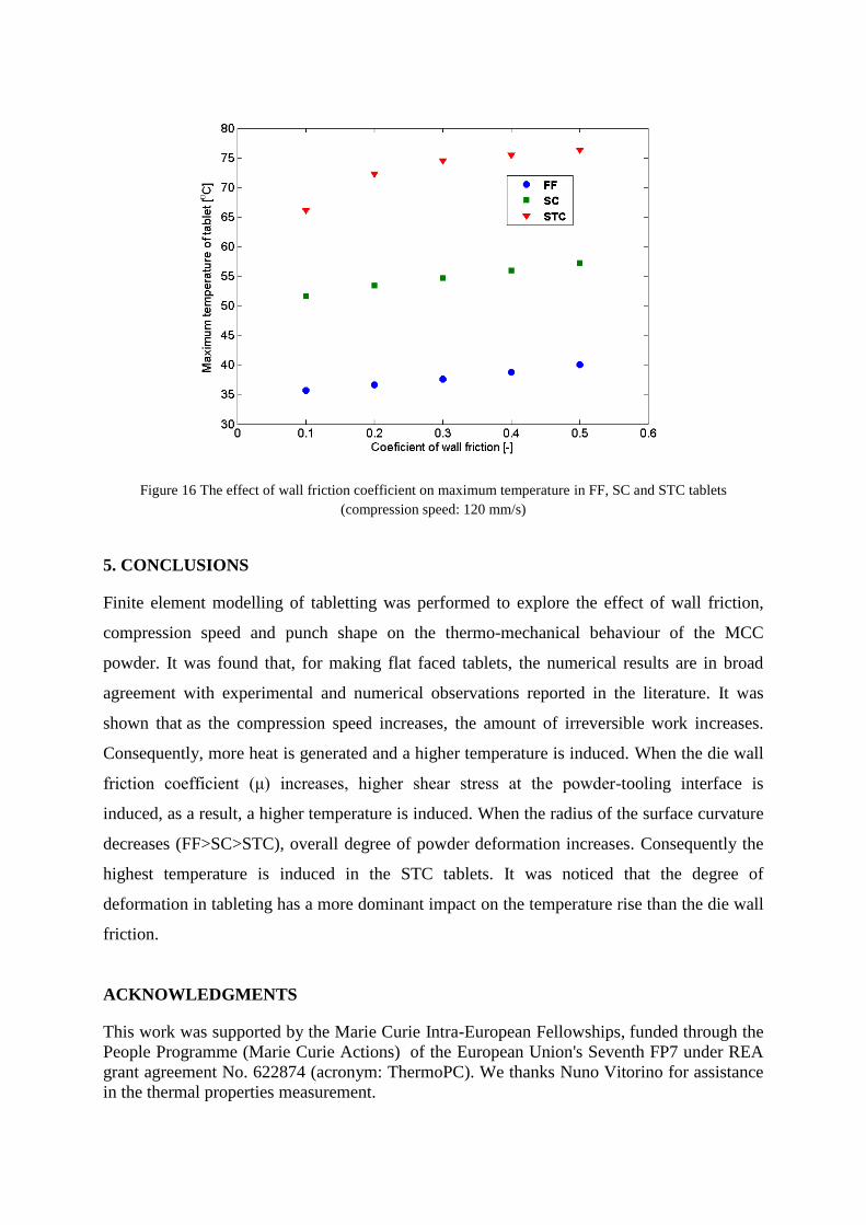
Figure 16 The effect of wall friction coefficient on maximum temperature in FF, SC and STC tablets
(compression speed: 120 mm/s)
5. CONCLUSIONS
Finite element modelling of tabletting was performed to explore the effect of wall friction,
compression speed and punch shape on the thermo-mechanical behaviour of the MCC
powder. It was found that, for making flat faced tablets, the numerical results are in broad
agreement with experimental and numerical observations reported in the literature. It was
shown that as the compression speed increases, the amount of irreversible work increases.
Consequently, more heat is generated and a higher temperature is induced. When the die wall
friction coefficient (μ) increases, higher shear stress at the powder-tooling interface is
induced, as a result, a higher temperature is induced. When the radius of the surface curvature
decreases (FF>SC>STC), overall degree of powder deformation increases. Consequently the
highest temperature is induced in the STC tablets. It was noticed that the degree of
deformation in tableting has a more dominant impact on the temperature rise than the die wall
friction.
ACKNOWLEDGMENTS
This work was supported by the Marie Curie Intra-European Fellowships, funded through the
People Programme (Marie Curie Actions) of the European Union's Seventh FP7 under REA
grant agreement No. 622874 (acronym: ThermoPC). We thanks Nuno Vitorino for assistance
in the thermal properties measurement.
LIST OF SYMBOLS
A Interacting area [m2]
Cp Specific heat [J.kg-1.K-1]
E Young’s modulus [Pa]
F Plastic flow potencial [Pa]
H Initial height [m]
I Identity matrix [-]
RE Cap eccentricity [-]
R Radius of the tablet [m]
RD Relative density [-]
RD0 bulk relative density [-]
S Tensor of deviator stress [Pa]
T Temperature [K]
d Cohesion [Pa]
k Thermal conductivity [W.m-1.K-1]
kf Thermal conductivity of full
dense material
[W.m-1.K-1]
kb Thermal conductivity of loose
powder
[W.m-1.K-1]
kI Thermal conductivity of
powder
[W.m-1.K-1]
kII Thermal conductivity of tool
steel
[W.m-1.K-1]
p Hydrostatic stress [Pa]
pa Evolution paramer [Pa]
pb Hydrostatic Yield stress [Pa]
q Mises equivalent stress [Pa]

pq Total heat source [W]
q Rate of internal heat
generation due to internal
friction
[W.m-3]
q Rate of external heat
generation due to wall friction
[W.m-2]
Iq
Rate of external heat
generation due to wall friction
to the powder
[W.m-2]
IIq
Rate of external heat
generation due to wall friction
to the die tools
[W.m-2]
υ Norm of the local slip velocity [ms-1]
α Coefficient of transition curve [-]
αT Thermal expansion coefficient [K-1]
β Internal friction angle [°]
σ Stress tensor [Pa]
σnn Local normal stress [Pa]
ρ Local density [kg.m-3]
εv Volume plastic strain increment [-]
η Weighting factor [-]
ν Poisson ratio [-]
λ Thermal diffusivity [m2s-1]
λI Thermal diffusivity of powder [m2s-1]
λII Thermal diffusivity of tool steel [m2s-1]
μ Wall friction coeficient [-]
ξ Inelastic heat fration [-]
REFERENCES

Arrifn, A. K., Rahman, M. M., Jumahat, A. (2003). An Experimental investigation of warm
poder compaction process, in: BSME-ASME International Conference on Thermal
Engineering, Dhaka, January
Arruda, E. M., Boyce , M. C., Jayachandran, R. (1995). Effects of strain rate, temperature and
thermomechanical coupling on the finite strain deformation of glassy polymers, Mech
Mater, 19, pp. 193-212
Bechard, S. R., Down, G. R. B. (1992). Infrared imaging of pharmaceutical materials
undergoing compaction, Pharm Res, 9, pp.521-528
Brevin, P. R., Coube, O., Doremus, P., Tweed, J. H. (2008). Modelling of powder die
compaction, New York: Springer.
Bever, M. B., Holt, D. L., Titchener, A. L. (1973). The stored energy of cold work, In:
Chalmers, B., Christian, J. W., Massalski, T. B., editors. Progress in Materials Science, 17,
pp. 5-88
Cespi, M., Bonacucina, G., Casettari, L., Ronchi, S., Palmieri, G. F. (2013). Effect of
temperature increase during the tableting of pharmaceutical materials, International Journal
of Pharmaceutics, 448, pp. 320-326
Cunningham, J. C., Sinka, I. C., Zavaliangos, A. (2004). Analysis of Tablet Compaction. I.
Characterization of Mechanical Behaviour of Powder and Powder/Tooling Friction,
Journal of Pharmaceutical Sciences, 93, pp. 2022-2039
Diarra, H., Mazel, V., Busignies, V., Tchoreloff, P. (2013). FEM simulation of the die
compaction of pharmaceutical products: Influence of visco-elastic phenomena and
comparison with experiments, International Journal of Pharmaceutics, 453, pp. 339-394
Grzesik, W. (2008). Advanced Machining Processes of Metalic Materials, Elsevier Science
Han, L. H., Elliott, J. A., Bentham, A. C., Mills, A., Amidon, G. E., Hancock, B. C. (2008).
A modified Drucker-Prager Cap model for die compaction simulation of pharmaceutical
powders, International Journal of Solids and Structures, 45, pp. 3088-3106
Hanus, E. J., King, L. D. (1968). Thermodynamic effects in the compression of solids,
Journal of Pharmaceutical Sciences, 57, pp.677-684
Kadiri, M. S., Michrafy, A. (2013). The effect of punch’s shape on die compaction of
pharmaceutical powders, Powder Technology, 239, pp. 467-477
Kaschnitz, E., Hofer, P., Funk, W. (2012). Thermophysical Properties of a Hot-Work Tool-
Steel with High Thermal Conductivity, International Journal of Thermophysics, 34, pp.
843-850
Ketolainen, J., Ilkka, J., Paronen, P. (1993). Temperature changes during tableting measured
using infrared thermoviewer, International Journal of Pharmaceutics, 92, pp.157-166
Ketolainen, J., Kubičak, Ľ., Boháč, V., Markovič, Paronen, P. (1995). Thermophysical
Properties of Some Pharmaceutical Excipients Compressed in Tablets, 12, pp. 1701-1707
Klinzing, G. R., Zavaliangos, A., Cunningham, J., Macaro, T., Winstead, D. (2010).
Temperature and density evolution during compaction of a capsule shaped tablet,
Computers and Chemical Engineering, 34, pp.1082-1091
Krok, A., Peciar, M., Fekete, R. (2014). Numerical investigation into the influence of the
punch shape on the mechanical behaviour of pharmaceutical powders during compaction,
Particuology, 16, pp. 116-131
Mazor, A., Perez-Gandarillas, L., de Ryck, A., Michrafy, A. (2016). Effect of roll compactor
sealing system designs: A finite element analysis, Powder Technology, 289, pp. 21-30
Michrafy, A., Haas, S., Kadiri, M., Sommer, K., Dodds, J. (2006). The effects of ambient
temperature on the compaction of pharmaceutical powders, Proc I MECH E Part E J
Process Mech Eng 220, pp.1-6
Michrafy, A., Ringenbacher, D., Tchoreloff, P. (2002). Modelling the compaction behaviour
of powders: application to pharmaceutical powders, Powder Technology, 127, pp. 257-266
Muliadi, A. R., Litster, J. D., Wassgren, C. R. (2013). Validation of 3-D element analysis for
predicting the density distribution of roll compacted pharmaceutical powder, Powder
Technology, 237, Pages 386-399
Nürnberg, E., Hopp, A. (1981). Temperature measurement during tableting, Pharm.
Technology, 168, pp.81-101
Procopio, A. T., Zavaliangos, A., Cunningham, J. C. (2003). Analysis of the diametrical
compression test and the applicability to plastically deforming materials. Journal of
Materials Science, 38, pp. 3629-3639
Rahman, M. M., Ariffin, A. K., Nor, S. S. M. (2009). Development of a finite element model
of metal powder compaction process at elevated temperature, Applied Mathematical
Modelling, 33, pp. 4031-4048
Reznikov, A. N. (1981). Thermophysical Aspects of Metal Cutting Processes (In Russian),
Mashinostroenie, Moscow, (1981)
Roue’che, E., Serris, E., Thomas, G., Périer-Camby, L. (2006). Influence of temperature on
the compaction of an organic powder and the mechanical strength of tablets, Powder
Technology, 162, pp. 138-144
Sinha, T., Curtis, J. S., B. C. Hancock, B. C., Wassgren, C. (2010). A study on the sensitivity
of Drucker-Prager Cap model parameters during the decompression phase of powder
compaction simulations, Powder Technology, 198, pp. 315-324
Sinka, C., Cocks, A. C. F.: "Modelling Die Compaction in the Pharmaceutical Industry", in
Brewin, P. R., Coube, O. , Doremus, P., Tweed, J. H., Editors, Modelling of Powder Die
Compaction, Springer-Verlag, London, 2008

Sinka, I. C., Cunningham, J. C., Zavaliangos, A. (2003). The effect of wall friction in the
compation of pharmaceutical tablets with curved faces: a validation study of the Drucker-
Prager Cap model, Powder Technology, 133, pp. 33-43
Travers, D. N., Merriman, M. P. (1970). Temperature changes occurring during the
compression and recompression of solids, Journal of Pharmacy and Pharmacology, 22,
pp.11S-16S
Train, D. (1957). Transmission of forces through a powder mass during the process of
pelleting. Transactions of the Institution of Chemical Engineers, 35, pp. 258-266
Wu, C.Y., Ruddy, O.M., Bentham, A.C., Hancock, B.C., Best, S.M., Elliott, J.A. (2005).
Modelling the mechanical behaviour of pharmaceutical powders during compaction,
Powder Technology, 152, pp. 107-117
Wu, C.Y., Hung, W.L., Miguélez-Morán, A. M., Gururajan, B., Seville. J.P.K. (2010). Roller
compaction of moist pharmaceutical powders. International Journal of Pharmaceutics, 391,
pp. 90–97
Zavaliangos, A., Galen, S., Cunningham, J., Winstead, D. (2007). Temperature evolution
during compaction of pharmaceutical powders, Journal of Pharmaceutical Sciences, 97, pp.
3291-3304
Zhang, G. G. Z., Law, D., Schmitt, E. A., Qiu, Y. (2004). Phase transformation considerations
during process development and manufacture of solid oral dosage forms. Advanced Drug
Delivery Reviews, 56(3), pp. 371-390