finite element analysis of the effects of bolt condition...
TRANSCRIPT
36
Transportation Research Record: Journal of the Transportation Research Board, No. 2545, Transportation Research Board, Washington, D.C., 2016, pp. 36–45.DOI: 10.3141/2545-05
The rail joint is typically considered to be one of the weakest locations in the track superstructure. Defects and failures—including bolt hole cracks, head–web cracking or separation, broken or missing bolts, and joint bar cracking—have been found to start at rail joints and the area surrounding these joints. The initiation and propagation of these defects are primarily attributable to the discontinuities of both geometric and mechanical properties in the rail joint area and the high-impact loads induced by the discontinuities. Loosened or missing rail joint bolts can decrease the overall stiffness at the joint. A loosened rail joint can also accelerate certain types of defects, such as cracking around the bolt hole and the head–web fillet area (the upper fillet area) close to the rail end. These cracks present both economical and safety concerns as they can significantly reduce the service life of the rail or joint bar and even lead to breaks in the rail. However, the effect of bolt condition on stress propagation around bolted rail joints is not thoroughly understood. This study investigated the effects of bolt loading and missing-bolt con-figurations on the stress distribution at the bolt hole and the upper fillet area under static loading conditions. A comprehensive parametric analy-sis was performed with finite element modeling. Preliminary results showed that when bolt loading increased, the rail vertical displacement and stresses on the rail upper fillet decreased, but the stresses on bolt holes increased. The two center bolts, which were closest to the rail end, were the most sensitive bolts in terms of variation in stresses in response to changes in bolting and torqueing.
Rail joints are used to connect two adjoining rails that are placed end to end. A typical rail joint has two joint bars placed on each side of the two adjoining rails and is connected with four or more bolts to ensure proper contact between the rail and joint bars. Generally, rail joints are classified into two categories: insulated joints and bolted joints. Insulated joints can be further categorized as either bonded or nonbonded. Bonded insulated joints consist of joint bars that are epoxied to the rails, while nonbonded joints are essentially bolted joints with electrical insulating properties. Bolted joints can be further categorized as compromise joints and standard joints. Compromise joints are installed to connect two rails with dissimilar sections, while standard joints are used to join two similar rail sections. Standard joints are typically used in bolted-joint rail track; they are also used in continuously welded rail track as tem-
porary joints to connect long continuously welded rail strings before welding occurs, with the two centermost bolt holes left blank (1). This study will focus on standard joints that are used in bolted-joint rail track.
Rail joints are often considered to be one of the weakest spots in track superstructure, mainly because of the discontinuities of both geo-metric and mechanical properties that arise as a result of the nature of rail gap, height mismatch and dip angle (as shown in Figure 1a), as well as a lower bending stiffness (as shown in Figure 1b) at the rail joint compared with regular track (2). Those discontinuities can lead to high-impact loads when the wheels pass over the rail joints, which may cause or exacerbate defects, including rail-end batter, loosened bolts, deteriorated support condition, and excessive deflec-tion, eventually leading to possible failure modes such as bolt hole cracks, head–web separation, bent or broken bolts, and cracked or broken joint bars (4, 5).
Bolt hole cracks and head–web separations are two of the most common defects that can develop in the rail joint area (Figure 2, a and b). These defects can cause rail breaks or loss of rail running surface. However, the initial cracks are difficult to detect because they are covered by joint bars, thus limiting or eliminating the effec-tiveness of inspection methods that rely on either human vision or machine vision.
Typically, bolt hole cracks start at the bolt hole on the very end of the receiving rail at a direction that is approximately 45° to the neutral axis of the rail (6–8) (Figure 2a). Previous research has identified the primary driving force for bolt hole cracks in bolted-joint rail track as the positive shear stress around the bolt hole (9, 10). This shear stress is proportional to the wheel–rail impact load and can be further magnified by the stress-concentration effect of the hole (9, 10). However, the bolt hole cracks in temporary joints in contin-uously welded rail track are typically generated by thermal-induced longitudinal stresses (8, 11). The Manual for Railway Engineering of the American Railway Engineering and Maintenance-of-Way Asso-ciation (AREMA) (referred to in this paper as the “AREMA Manual”) suggests the following practices for mitigation and prevention of bolt hole cracks: (a) ensure proper hole drilling and dressing to prevent uneven stress around the hole or apply work hardening to the holes to introduce residual compressive stress; (b) implement regular track surfacing and other track maintenance to prevent excessive vertical deflection in the bolt area; and (c) ensure joint bars fit properly, bolts are kept tight, and rail restraints are adjusted to prevent longitudinal stresses (3).
Rail head–web separation is a progressive horizontal defect, which may occur at rail joints or other locations along the track, originating from the fillet area between the head and web, Head–web separations at joint areas generally start at the rail end and propagate over bolt holes until reaching the rail running surface. This defect is primarily
Finite Element Analysis of the Effects of Bolt Condition on Bolted Rail Joint Stresses
Kaijun Zhu, J. Riley Edwards, Yu Qian, and Bassem Andrawes
Rail Transportation and Engineering Center–RailTEC, Department of Civil and Environmental Engineering, University of Illinois at Urbana–Champaign, 205 North Mathews Avenue, Urbana, IL 61801. Corresponding author: Y. Qian, [email protected].

Zhu, Edwards, Qian, and Andrawes 37
Dip angle
Receiving rail
Rail height mismatch
Rail gap
(a)
Portions tobe removed(typical)
Area = 11.22 in.2 (72.39 cm2)Moment of inertia about the neutral axis = 65.5 in.4 (2,730 cm4)
For two barsArea = 10.70 in.2 (69.03 cm2)Moment of inertia about the neutral axis = 23.3 in.4 (970 cm4)
115 RE
115 RE Joint Bars
(b)
FIGURE 1 Discontinuity of (a) geometry including rail gap, height mismatch, and dip angle (2) and (b) mechanical properties (3).
Rail-endbolt holecracks
Head–webseparation(upper filletcrack)
(a)
(b)
(c)
FIGURE 2 Typical (a) rail-end bolt hole crack (2), (b) head–web separation (3), and (c) missing bolts (3).
around the rail-end bolt hole and at the upper fillet area. This paper will present the preliminary results from numerical simulations of standard bolted joints under static loading conditions.
Methodology
Because FE analysis is one of the most popular and powerful numerical simulation methods for solving complicated structural and mechanical problems, it was chosen for use in this study. A commercially available software (Abaqus/CAE) was selected to per-form simulations for bolted rail joints with different missing-bolt configurations and bolt loadings.
The bolted rail joints modeled in this study were head-free standard joints installed on 115 RE rails. The standard design and other relative information are given in Figure 4-3-1 in the AREMA Manual (3). This rail section, 115 RE, is used for both freight railroad and rail transit systems in North America. Figure 3 presents the numerical model in this study, which consists of four major components: rails, joint bars, simplified bolts, and rail extensions. The first three components were modeled as three-dimensional (3-D) deformable solids, while the rail extensions were modeled as deformable wires. More specifically, each rail was meshed with 45,965 linear hexahedron elements, each joint bar with 33,239 linear tetrahedron elements, each simplified bolt with 2,576 linear hexahedron elements, and each rail extension with 40 cubic beam elements assigned rail section properties, such as rail
caused by a fatigue failure resulting from the excessive, repeated vertical impact loads and deflections or improper rail–joint bar fit during installation. To prevent head–web separation, the AREMA Manual recommends improved steel quality and proper track main-tenance with attention to the proper contact between rail and joint bars, especially in the upper fillet area (3).
By using data from FRA’s accident database from 2000 to 2010, 249 accidents were categorized as occurring because of rail joint failures (4). Broken and missing bolts, as shown in Figure 2c, were one of the primary causes for these accidents. There was a sharp decrease in the number of accidents related to rail joint failures between 2008 and 2010, which may be attributable to the improve-ments in inspection procedures and capabilities and might also be linked to the 2007 FRA mandate requiring more frequent rail joint inspections. The number of accidents caused by broken and miss-ing bolts decreased the most, with no related accidents reported, in calendar years 2008 and 2010, possibly because of more frequent inspection and improved maintenance (4).
Despite these reductions in accidents and improvements in main-tenance practices, additional gains are still possible. For advance-ments to continue to be made in this field, the effect of bolt condition (e.g., missing bolts and variable bolt loadings) on the propagation of stresses should be thoroughly understood. Such research would fill knowledge voids relating to how bolt conditions affect the stresses around the rail-end bolt hole and at the upper fillet area. The occur-rence of high stresses in these areas is directly related to the bolt hole crack and head–web separation defects.
Recent research in the Rail Transportation and Engineering Center at the University of Illinois at Urbana–Champaign has been focused on a parametric analysis with finite element (FE) modeling of the effect of missing-bolt configurations and bolt loadings on stress distribution

38 Transportation Research Record 2545
area, moment of inertia, and location of the neutral axis. The coefficient of friction between all the components was set at 0.4 (2).
Relevant Simplifications
Three important simplifications were made to the bolted joint models to reduce the computational cost for the parametric study. First, the rails modeled with 3-D deformable solid elements were each only 36 in. (91.4 cm) long, and the remaining 180 in. (457.2 cm) of each rail were simplified by using beam elements assigned the properties of the rail section. A typical theoretical simplification previously proposed by Timoshenko and Langer (12) and other researchers uses beam theory and treats the rail as a uniform beam supported by a continuous, linear and elastic foundation. The rail extension was tied to the centroid of rail cross section, with all three translational and three rotational degrees of freedom transferred from the centroid to one end of the rail extension. The adoption of the beam elements to model the rail extensions significantly reduced the computational cost, compared with the more demanding alternative of extending the
rail with 3-D deformable solid elements. Meanwhile, because the sim-plification was made far from the bolted rail joint (the primary zone of interest in this study), the influence on the stress distribution on the joint area was negligible. The lengths of the rails simulated with dif-ferent elements in this study were finalized through a trial-and-error process, which optimized both computational accuracy and expense.
Second, the combination of the bolt, nut, and washer was simpli-fied to a single component with the bolt preload calculated with Equa-tion 1 in SI units (2). The stress distribution between the threaded bolt and nut itself is very complicated and is beyond the scope of this study (13).
=PT
KDb (1)
where
Pb = bolt preload (kN), T = bolt torque moment (N-m), K = coefficient of the bolt torque moment (0.19 to 0.25), and D = bolt diameter (mm).
PartRail
Joint bar
Rail extensions
Part Type
3-D deformable solid
Deformable wire
Simplified bolts
Element TypeLinear hexahedron
Linear tetrahedron
Cubic beam
Linear hexahedron
Number of Elements45,965
33,239
40
2,576
22.5 in.
57.2 cm
22.5 in.
Wheel Load
Wheel Load
57.2 cm
9 in.
A B
C
22.9 cm
9 in.
22.9 cm
22.5 in.
57.2 cm
22.5 in.
57.2 cm
(a)
(c)
(b)
C
B
A
FIGURE 3 Numerical model: (a) front view, (b) side view of bolted rail joint and its FE model, and (c) detailed mesh properties (A 5 rail end to capture the vertical displacement; B 5 rail-end bolt hole around which to capture the largest tensile stress; C 5 rail-end upper fillet to capture the largest von Mises stress).
Zhu, Edwards, Qian, and Andrawes 39
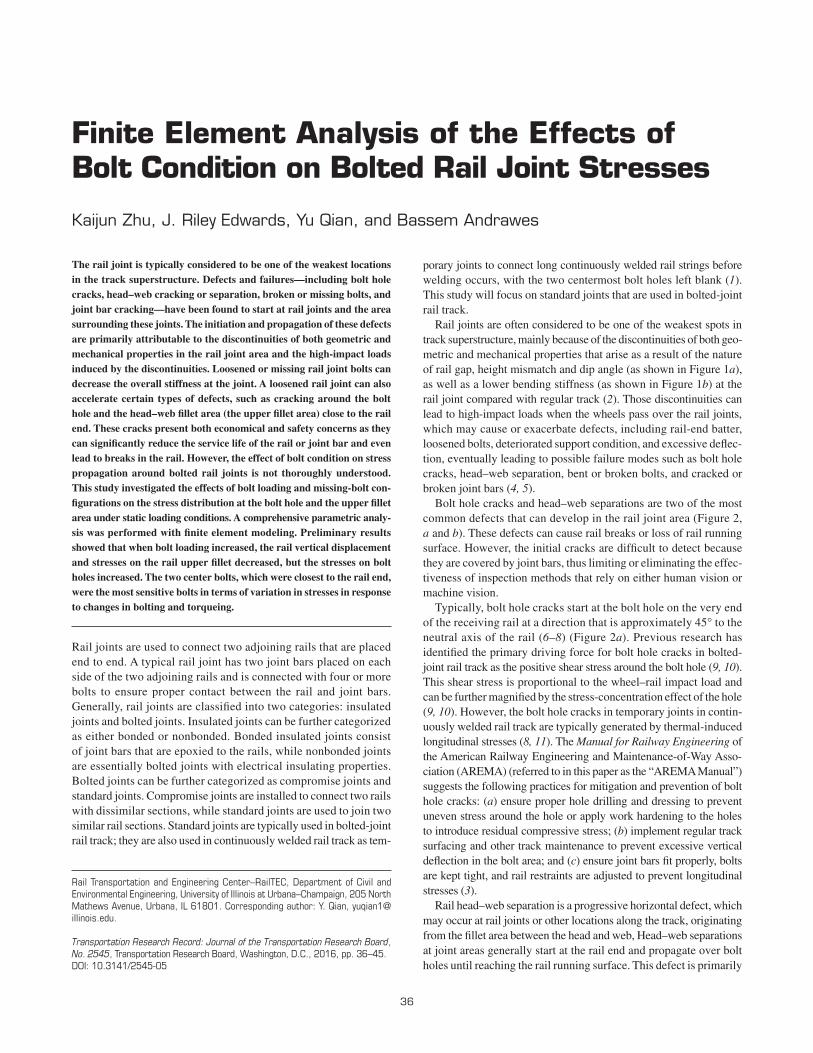
The bolts used for the 115 RE rail joint had a diameter, D, of 25.4 mm (1 in.). The other parameters were chosen as T = 500 N-m (4,425 lb • in.), and K = 0.2. Thus, the bolt preload, Pb, was calcu-lated as 98.4 kN per bolt, or approximately 22,000 lb per bolt. The AREMA Manual also provides relative information about track preload in Chapter 5, Section 5.5, pointing out that the bolt preload should be within a range of 20,000 to 30,000 lb (89.0 to 133.4 kN) per bolt for the initial tightening and within a range of 15,000 to 25,000 lb (66.7 to 111.2 kN) per bolt for subsequent torqueing (3). The bolt was assumed to be installed perfectly along the central axis of the rail bolt hole during simulation.
Third, the models were carried out in the vertical direction, and only the vertical bending was captured. Accordingly, (a) the wheel load was applied vertically and symmetrically in the longitudinal direction of the rail to eliminate minor axis and torsional bending; this simpli-fication reduced the computational time by avoiding the inclusion of detailed fastening system components (and it might underestimate the magnitude of the largest stresses to a certain extent) and (b) the support reactions were simplified with only the vertical springs placed at the center of the crossties. The spring stiffness was calculated by using the Timoshenko beam theory (12). This simplification is rea-sonable for permanent bolted joints on bolted-joint rail track that experience small longitudinal thermal stresses.
Although all the assumptions and simplifications affect the magni-tude of the deflections and stresses calculated with FE modeling, the goal of this paper was to provide a comparison between different bolt conditions. Once the modeling parameters have been calibrated with laboratory experimental results from subsequent projects, additional quantitative simulation and comparison will be performed.
Constants, Variables, and outputs for Parametric Study
A parametric study was carried out to investigate the effects of bolt conditions, including different missing-bolt configurations and load-ings, on the stresses distributed around bolted rail joints. The primary emphasis was on rail-end bolt hole stress and rail upper fillet stress. The influences of bolt conditions were distinguished from those of other variables by adopting the method of control variables and setting many of these variables—including the rail section, track foundation, and wheel loading—as constants. All constants, variables, and out-puts that were considered in the FE models are listed in Table 1 and are introduced in detail in the following subsections.
Constants
track Foundation The track stiffness of 4,000 pounds per square inch (psi) (27.6 MPa) was obtained from field measurements at New York City Transit. Typical embedded tracks have a much higher track stiffness, with the exception being systems with resilient plates between the rail and crossties. This lower track stiffness was selected because it was expected to lead to greater deflections and thus larger bending stresses. In addition, 4,000 psi (27.6 MPa) is also close to the typi-cal track stiffness of 3,000 psi (20.7 MPa) measured from regular ballasted track. As mentioned earlier, all of the crossties were simpli-fied by attachment of the vertical springs to the bottom of the rail. The spring stiffness was calculated as 90,000 lb/in. (157.6 kN/cm) by using the Timoshenko beam theory with Equation 2 below (12).
= ×spring stiffness track stiffness crosstie spacing (2)
More specifically, a group of nine (3×3) springs, each with an individual stiffness of 10,000 lb/in. (17.5 kN/cm) was used to rep-
resent each crosstie underneath the 3-D rail, while one spring with a stiffness of 90,000 lb/in. (157.6 kN/cm) was used to represent the crosstie underneath each rail extension.
In terms of joint support, the suspended joint is less stiff than the supported joint, so use of this joint would lead to greater deflection and bending stress. However, the greater stiffness of the supported joint might cause larger dynamic wheel loads and more severe rail-end batter. Because this paper covers static FE model simulations, and the dynamic wheel load is a constant, the suspended joint was selected. The shorter distance between the two center crossties will likely increase the stiffness, and this practice is often adopted in the field to enhance the performance of suspended joint.
Wheel load The static wheel load of 16,500 lb (73.4 kN) per wheel was obtained from New York City Transit and is relatively heavy compared with the wheel loads for other heavy rail transit systems. However, the heaviest static wheel load in a freight sys-tem can be much higher, within the range of 32,000 to 39,000 lb (142.3 to 173.5 kN) per wheel.
The impact factor of the wheel load varies depending on condi-tions, especially at rail joint areas; conditions include irregularities in the shape of the wheel and rail, speed of the train, and track stiff-ness at the joint. There are two kinds of impact forces at rail joints: (a) short-duration peak impact force, P1, which occurs instantly after the wheel crosses the joint and disappears quickly, so that it plays an important role in causing the rail-end batter and (b) delayed peak impact force, P2, which happens after the first peak and lasts for a longer period, so that it could be transferred further down to the structure below the rail. This force is associated with rail bending (14). For this paper, the impact factor was set as a constant of 3.0 based on the current value found in the AREMA Manual. This value suggests a 200% increase over static vertical loads to estimate the dynamic effect of wheel and rail irregularities (3).
For the experiments conducted and analyzed in this paper, the wheel load was applied on top of the fourth rail-end bolt hole.
TABLE 1 Constants, Variables, and Outputs for Parametric Study
Parameter Value
Constant
Rail section 115 RE Track foundation Track stiffness 4,000 psi (27.6 MPa) Crosstie spacing 22.5 in. (57.2 cm) Equivalent spring stiffness 90,000 lb/in. (157.6 kN/cm) Joint support type Suspended with two center crossties
spaced 18 in. (45.7 cm) away Wheel load Static wheel load 16,500 lb (73.4 kN) per wheel Impact factor 3.0 Dynamic wheel load 50,000 lb (222.4 kN) per wheel Loading position Right above the rail-end bolt hole
Variable
Bolt configurations No bolt missing 1 possible configuration One bolt missing 6 possible configurations Two bolts missing 15 possible configurations
Bolt loadings Standard 22,000 lb (97.9 kN) per bolt Loosened 6,000 lb (26.7 kN) per bolt Overtightened 35,000 lb (155.7 kN) per bolt
Note: Outputs are the largest vertical displacement at rail end, the largest tensile stress around rail-end bolt hole, and the largest von Mises stress at rail fillet.

40 Transportation Research Record 2545
This location was selected on the basis of the results of previous FE model simulations conducted at the University of Illinois at Urbana–Champaign, in which the wheel was loaded at different locations on the rail joint. Findings from this study indicated that the rail-end bolt hole stress reaches its maximum value when the wheel is directly above it, while the rail-end fillet stress reaches its peak when the wheel is at the rail end. This paper only shows the results calculated from the simulations with the wheel loaded right above the rail-end bolt hole; other results will be presented in future papers.
Variables
Bolt Configurations Bolt configurations include three categories: no missing bolts, one missing bolt, and two missing bolts. All 22 possible bolt configurations are shown in Figure 4.
Bolt loadings As calculated with Equation 1, the standard bolt loading was 22,000 lb (97.9 kN) per bolt, which is within the recom-mended range of bolt loading described in the AREMA Manual. When the bolt was loosened, the bolt loading was set at a much lower value of 6,000 lb (26.7 kN) per bolt, which was expected to cause a decrease in the stiffness at the joint. When the bolt was overtightened, the bolt loading was set at a high value of 35,000 lb (155.7 kN) per bolt, which would increase the stiffness at the joint.
Outputs
The key outputs of the FE models were as follows: (a) the largest vertical displacement were observed at the rail end, which cor-responds to the stiffness of the bolted joint (measured at midbottom of the loaded rail end); (b) the largest tensile stress was observed around the rail-end bolt hole, which is directly related to the rail-end bolt hole crack problem (measured around the fourth bolt hole); and (c) the largest von Mises stress was observed at the rail-end fillet area, which is directly related to the head–web separation problem (measured at the rail-end upper fillet of the loaded rail). The specific locations where those results were collected from the FE models are shown in Figure 3.
Parametric Study Procedures
Two steps were used to capture the effects of both the missing-bolt configurations and bolt loadings on the stress distribution around the bolted rail joint (Figure 5).
In Step 1, the bolt preload was set to the standard loading of 22,000 lb (97.9 kN), and the FE model simulations with all types of missing-bolt configurations were calculated. The results from the case of no missing bolts were used as a reference to obtain the impacts of different missing-bolt configurations; the reference results were
No Bolt Missing (1) One Bolt Missing (6) Two Bolts Missing (15)
1 2 3 4 5 6 1 2 3 4 5 6
1 2 3 4 5 6
1 2 3 4 5 6
1 2 3 4 5 6
1 2 3 4 5 6
1 2 3 4 5 6
1 2 3 4 5 6
1 2 3 4 5 6
1 2 3 4 5 6
1 2 3 4 5 6
1 2 3 4 5 6
1 2 3 4 5 6
1 2 3 4 5 6
1 2 3 4 5 6
1 2 3 4 5 6
1 2 3 4 5 6
1 2 3 4 5 6
1 2 3 4 5 6
1 2 3 4 5 6
1 2 3 4 5 6
1 2 3 4 5 6
Bolt is present
Bolt is missing0
0
FIGURE 4 Missing-bolt configurations considered in the parametric study (the wheel is loaded right above the fourth bolt hole).
No Bolt Missing
One Bolt Missing
Two Bolts Missing
Bolts preloaded at 22,000 lb (97.9 kN)
Compared with Most representative
bolt-missingconfigurations
Bolts loosened at 6,000 lb (26.7 kN)
Bolts overtightened at 35,000 lb (155.7 kN)
STEP 1 STEP 2
Select
Applied to
Applied toCompared with
FIGURE 5 The two major steps of the parametric study.

Zhu, Edwards, Qian, and Andrawes 41
compared with the results from the cases of one missing bolt and two missing bolts. The most representative missing-bolt configurations were then selected to be studied in the next step.
In Step 2, the FE model simulations with the chosen missing-bolt configurations were set at different levels of bolt loading. The results were compared to present the influences resulting from loosened (6,000 lb or 26.7 kN) or overtightened (35,000 lb or 155.7 kN) bolts.
ReSultS and diSCuSSionS
The results calculated for the parametric study are presented to show the effects of missing-bolt configurations and bolt loadings on the vertical displacement at the rail end, bolt hole tensile stress around the rail-end bolt hole, and von Mises stress at the rail-end upper fillet.
Bolt Configurations
The influences of the bolt configurations are shown by illustrating the results for the case of no missing bolts in detail, first as datum points, followed by a series of results for the cases of one missing bolt and two missing bolts.
No Missing Bolts
The vertical displacement (Figure 6a), principle stress around the fourth rail-end bolt hole (Figure 6b), and von Mises stress at the rail-end upper fillet (Figure 6c) are shown and described in detail below.
Figure 6a shows that a rail with a bolted joint deflects similarly to continuous rail. However, with the loading applied above the fourth bolt hole, more deflection was observed at the right adjoining rail,
(psi)(Avg: 75%)S. Mises
(psi) (psi)
+6.842 E+04+6.272 E+04+5.702 E+04+5.132 E+04+4.562 E+04+3.992 E+04+3.422 E+04+2.852 E+04+2.282 E+04+1.712 E+04+1.142 E+04+5.722 E+03+2.181 E+01
(Avg: 75%)S. Max. Principal (Abs)
+2.416 E+04+2.088 E+04+1.760 E+04+1.433 E+04+1.105 E+04+7.777 E+03+4.501 E+03+1.225 E+03–2.050 E+03–5.326 E+03–8.602 E+03–1.188 E+04–1.515 E+04
(Avg: 75%)S. Mises
+6.139 E+04+5.630 E+04+5.121 E+04+4.612 E+04+4.102 E+04+3.593 E+04+3.084 E+04+2.575 E+04+2.066 E+04+1.556 E+04+1.047 E+04+5.379 E+03+2.866 E+02
(in.)U, U2+8.373 E–03–7.152 E–03–2.268 E–02–3.820 E–02–5.372 E–02–6.925 E–02–8.477 E–02–1.003 E–01–1.158 E–01–1.313 E–01–1.469 E–01–1.624 E–01–1.779 E–01
108 in. (274.3 cm)
(a)
Note: Deformation Scale Factor = 100Only portion of the model is plotted, with the length of 108 in.1 in. = 2.54 cm.
(c)(b)
FIGURE 6 Illustration of the following for the case of no missing bolts (a) vertical displacement (U, U2) along the rail with a bolted joint, (b) principal stress [S. Max. Principal (abs)] around the fourth rail-end bolt hole, and (c) von Mises stress (S. Mises) at the rail-end upper fillet.

42 Transportation Research Record 2545
with the largest vertical displacement of 0.178 in. (0.452 cm) at this rail end.
Figure 6b presents the principal stress around the fourth rail-end bolt hole, which is directly under the wheel load. It is clearly shown that the maximum positive principal stress of 24,160 psi (166.6 MPa), in tension, acted at an angle of about 45° to the neutral axis of the rail. This specific angle implies the potential crack initiation angle, which agrees with the findings from previous researchers.
Figure 6c shows the von Mises stress distribution at the rail-end upper fillet area. The maximum von Mises stress was 61,390 psi (423.3 MPa), which occurred near the contact area between the rail-end upper fillet and the joint bar top. The magnitude of the fillet stress was relatively high, which might have been caused by the
limited contact area and the excessive relative movement around that area.
These maximum values of vertical displacement at the rail end, tensile stress around the bolt hole, and von Mises stress around the fillet were used as reference data to compare with the results from the cases of one missing bolt and two missing bolts.
One Missing Bolt
There are six possible missing-bolt configurations for the case with the wheel load fixed right above the fourth bolt hole. Figure 7 shows bar charts of rail-end vertical displacements (Figure 7a), bolt hole
(a)
(b)
(c)
Missing Bolt Location
Ver
tica
l Dis
pla
cem
ent
(in
.)
Ver
tica
l Dis
pla
cem
ent
(cm
)
Bo
lt H
ole
Str
ess
(psi
)
Bo
lt H
ole
Str
ess
(MP
a)
Missing Bolt Location
Up
per
Fill
et S
tres
s (p
si)
Up
per
Fill
et S
tres
s (M
Pa)
Missing Bolt Location
Note: -0.178 in. (0.452 cm) is the reference datum from the case of no bolt missing.
Note: 24,160 psi (166.6 MPa) is the reference datum from the case of no bolt missing.
Note: 61,390 psi (423.3 MPa) is the reference datum from the case of no bolt missing.
FIGURE 7 Rail-end (a) vertical displacements, (b) bolt hole tensile stresses, and (c) upper fillet von Mises stresses for the six cases of one bolt missing.

Zhu, Edwards, Qian, and Andrawes 43
tensile stresses (Figure 7b), and upper fillet von Mises stresses (Figure 7c) for the six configurations, each with a reference line showing the corresponding result for the case of no missing bolts.
Generally, from all three plots in Figure 7, it is clear that a missing third or fourth bolt (the two center bolts) had the greatest influence on deflections and stresses. Specifically, the greatest changes occurred when the fourth bolt was missing, with an increase of the vertical dis-placement of the rail end by 1.5% to 0.181 in. (0.459 cm), a decrease of the bolt hole tensile stress by 13.5% to 20,900 psi (144.1 MPa), and an increase of the upper fillet von Mises stress by 22.1% to 74,970 psi (516.9 MPa). With the third bolt missing, the rail-end verti-cal displacement increased by 1.1% to 0.180 in. (0.457 cm), the bolt hole tensile stress decreased by 5.4% to 22,860 psi (157.6 MPa), and the upper fillet von Mises stress increased by 6.1% to 65,140 psi (449.1 MPa). The removal of other bolts had little or no effect on the results of this study.
The increase in the vertical displacement was relatively limited; this result may be attributable to the closer spacing of the two center crossties underneath the bolted joint. The reduction of the bolt hole tensile stress is attributable to the release of the bolt load once the bolt is missing. The change in the upper fillet von Mises stress is the most notable of the three outputs, even with the modest increment of the vertical displacement, which indicates the high risk at the rail-end upper fillet.
Two Missing Bolts
Fifteen possible missing-bolt configurations were considered in this category. Table 2 shows the percentage changes of the rail-end vertical displacements, bolt hole tensile stresses, and upper fillet von Mises stresses for the fifteen configurations, with reference data for the case
of no missing bolts. The largest percentage changes for each location where outputs were monitored are shown in bold.
Table 2 shows results similar to those of the case of one missing bolt. The most extreme case occurred when the third and fourth bolts were missing. Under this condition, the vertical displacement of the rail end increased by 3.6% to 0.184 in. (0.468 cm), bolt hole tensile stress decreased by 18.3% to 19,750 psi (136.2 MPa), and upper fillet von Mises stress increased by 41.8% to 87,080 psi (600.4 MPa). Those noticeable changes were mainly attributable to the reduction of the stiffness caused by the absence of the two center bolts, lead-ing to larger displacements of the whole joint system and greater relative movements between rail ends and joint bars. In addition, the changes were distinct if either of the two center bolts was missing; this finding agrees with the findings in the case of one missing bolt. Another finding was that the bolt hole tensile stress increased by 4.8% to 25,330 psi (174.6 MPa) when the fifth and sixth bolts were missing. This result shows that the absence of bolts could also lead to a notable increase in bolt hole stress.
Bolt loadings
After the first part of the parametric study on missing-bolt configura-tions had been completed, the three most representative configura-tions, which were no bolts missing, fourth bolt missing, and third and fourth bolts missing, were chosen for the second part of this study on bolt loadings. Three bolt-loadings cases were considered, including standard preloaded (22,000 lb or 97.9 kN per bolt), loos-ened (6,000 lb or 26.7 kN per bolt), and overtightened (35,000 lb or 155.7 kN per bolt). The results of the standard preloaded case were presented in the previous part of the study and are used as reference data in this part.
TABLE 2 Results for Configurations with Two Bolts Missing
Rail End Vertical Displacements
Rail End Bolt-Hole Tensile Stresses
Rail End Upper Fillet von Mises Stresses
Reference Datum
❶ ❷ ❸ ❹ ❺ ❻ 0.178 in. 24,160 psi 61,390 psi(0.452 cm) (166.6 MPa) (423.3 MPa)
Configuration
① ② ❸ ❹ ❺ ❻ +0.2% +0.1% ±0.0%
① ❷ ③ ❹ ❺ ❻ +1.1% −5.3% +6.2%
① ❷ ❸ ④ ❺ ❻ +1.5% −13.5% +22.2%
① ❷ ❸ ❹ ⑤ ❻ +0.1% +0.5% ±0.0%
① ❷ ❸ ❹ ❺ ⑥ +0.1% +0.9% +0.1%
❶ ② ③ ❹ ❺ ❻ +1.3% −6.0% +8.3%
❶ ② ❸ ④ ❺ ❻ +1.6% −13.5% +22.1%
❶ ② ❸ ❹ ⑤ ❻ +0.2% +0.5% −0.1%
❶ ② ❸ ❹ ❺ ⑥ +0.1% +0.9% ±0.0%
❶ ❷ ③ ④ ❺ ❻ +3.6% −18.3% +41.8%
❶ ❷ ③ ❹ ⑤ ❻ +1.1% −4.9% +6.6%
❶ ❷ ③ ❹ ❺ ⑥ +1.1% −4.5% +6.2%
❶ ❷ ❸ ④ ⑤ ❻ +2.0% −11.9% +30.0%
❶ ❷ ❸ ④ ❺ ⑥ +1.5% −12.8% +22.1%
❶ ❷ ❸ ❹ ⑤ ⑥ +0.3% +4.8% +0.9%
Note: The wheel is loaded right above the fourth bolt hole.

44 Transportation Research Record 2545
Figure 8 shows the general trend that increased bolt loading led to decreased rail-end vertical displacements and upper fillet stresses and increased bolt hole tensile stresses. This tendency became less obvious when the fourth bolt was missing and might be negligible when both the third and fourth bolts are gone, a finding that again implies the significance of the two center bolts. In the case of no missing bolts, with the loosened bolts (6,000 lb or 26.7 kN per bolt), the vertical displacement of the rail end increased by 1.2%, bolt hole tensile stress decreased by 10.6%, and upper fillet von Mises stress increased by 7.6%, compared with the standard preloaded bolts (22,000 lb or 97.9 kN per bolt). With the overtightened bolts (35,000 lb or 155.7 kN per bolt), the vertical displacement of the rail end decreased by 0.6%, bolt hole tensile stress increased by 13.9%, and upper fillet von Mises stress decreased by 2.2%.
This part of the parametric study revealed that when the bolt load-ings increase, bolt hole stress and upper fillet stress move in opposite
directions one to the other. That is, if one of the stresses is decreased by increasing or decreasing (whichever is appropriate for that stress) the bolt loadings, the other stress would presumably be increased. Other improvements need to be included if both of the stresses need to be reduced.
ConClusions
To better understand the influence of loosened and missing bolts on the deterioration of rail joint components and the formation of severe defects and failures in the field, this study examined the effects of bolt conditions on the stress distributions of bolted rail joints, with the focus on the rail-end bolt hole and upper fillet areas. A paramet-ric study was performed by using FE modeling. More specifically, static FE models with three major simplifications were established
(a)
(b)
(c)
Ver
tica
l Dis
pla
cem
ent
(in
.)B
olt
Ho
le S
tres
s (p
si)
Up
per
Fill
et S
tres
s (p
si)
Bo
lt H
ole
Str
ess
(MP
a)U
pp
er F
illet
Str
ess
(MP
a)V
erti
cal D
isp
lace
men
t (c
m)
Note: Percentages are calculated using result under standard bolt preload as datum for each case.
FIGURE 8 Rail-end (a) vertical displacements, (b) bolt hole tensile stresses, and (c) upper fillet von Mises stresses for three bolt loadings.

Zhu, Edwards, Qian, and Andrawes 45
to solve the problem. According to the results from this FE model parametric study, the following conclusions can be drawn:
• The center two bolts play the most significant role of the six bolts. The removal of both center bolts would lead to a 3.6% increase of rail-end vertical displacement and a 41.8% increase of rail-end upper fillet stress; however, the rail-end bolt hole stress would decrease by 18.3%.• If all bolts are present, when bolt loadings increase, the rail-end
vertical displacement and upper fillet stress decrease, but the rail-end bolt hole stress increases.• If both the bolt hole stress and the upper fillet stress need to be
mitigated, other improvements should be considered in addition to adjusting the bolt loadings.
aCknoWledgMentS
This research was funded in part by Parsons Brinckerhoff (PB), under contract to New York City Transit (NYCT), and the National University Rail Center, or NURail, and was based on background information provided under a broader research program for PB and NYCT. The authors thank PB, NYCT Inspections and Testing, and NYCT Track Engineering for providing leadership and oversight for the broader work with which this paper was associated. The authors also thank Don Uzarski and Michael Yang from the University of Illinois at Urbana–Champaign (UIUC) and Michael Carolan from the Volpe National Transportation Systems Center for their assistance and advice. J. Riley Edwards has been supported in part by grants to the UIUC Rail Transportation and Engineering Center (RailTEC) from CN, the Canadian National Railway Company; Hanson Professional Services; and the George Krambles Transportation Scholarship Fund.
ReFeRenCeS
1. Akhtar, M. N., and D. D. Davis. Load Environment of Rail Joint Bars—Phase I: Effects of Track Parameters on Rail Joint Stresses and Crack Growth. Final Report No. DOT/FRA/ORD-13/24. Federal Railroad Administration, U.S. Department of Transportation, 2013. https://www .fra.dot.gov/eLib/details/L04515.
2. Wen, Z., X. Jin, and W. Zhang. Contact-Impact Stress Analysis of Rail Joint Region Using the Dynamic Finite Element Method. Wear, Vol. 258, No. 7, 2005, pp. 1301–1309.
3. American Railway Engineering and Maintenance-of-Way Association (AREMA). Manual for Railway Engineering. Lanham, Md., 2005.
4. Jeong, D. Y., R. Bruzek, and A. Tajaddini. Engineering Studies on Joint Bar Integrity, Part I: Field Surveys and Observed Failure Modes. Pro-ceedings of the 2014 Joint Rail Conference, JRC 2014-3706, April 2–4, 2014, Colorado Springs, Colo.
5. Carolan, M. E., D. Y. Jeong, and A. B. Perlman. Engineering Studies on Joint Bar Integrity, Part II: Finite Element Analysis. Proceedings of the 2014 Joint Rail Conference, JRC 2014-3708, April 2–4 2014, Colorado Springs, Colo.
6. Orringer, O., J. M. Morris, and R. K. Steele. Applied Research on Rail Fatigue and Fracture in the United States. Theoretical and Applied Fracture Mechanics, Vol. 1, No. 1, 1984, pp. 23–49.
7. Jeong, D. Y. Progress in Rail Integrity Research. Final Report No. DOT/FRA/ORD-01/18. Federal Railroad Administration, U.S. Department of Transportation, 2001.
8. Mayville, R. A., and P. D. Hilton. Fracture Mechanics Analysis of a Rail-End Bolt Hole Crack. Theoretical and Applied Fracture Mechanics, Vol. 1, No. 1, 1984, pp. 51–60.
9. Mayville, R. A., and R. G. Stringfellow. Development and Application of Rail Defect Fracture Models to Assess Remedial Actions. Final Report No. DOT/FRA/ORD-93/33. Federal Railroad Administration, U.S. Department of Transportation, 1993.
10. Mayville, R. A., and R. G. Stringfellow. Numerical Analysis of a Rail-road Bolt Hole Fracture Problem. Theoretical and Applied Fracture Mechanics, Vol. 24, No. 1, 1995, pp. 1–12.
11. Sih, G. C., and D. Y. Tzou. Rail-End Bolt Hole Fatigue Crack in Three Dimensions. Theoretical and Applied Fracture Mechanics, Vol. 3, No. 2, 1985, pp. 97–111.
12. Timoshenko, S., and B. F. Langer. Stresses in Railroad Tracks. Transac-tions ASME, Vol. 54, 1932, pp. 277–302.
13. Li, X., H. Nie, W. Yuan, and B. Wen. Simulation of Fatigue Failure of Rail Joint Bolts by FEA. Advanced Engineering Forum, Vol. 2, 2011, pp. 1035–1040.
14. Jenkins, H. H., J. Stephenson, G. Clayton, G. Morland, and D. Lyon. The Effect of Track and Vehicle Parameters on Wheel/Rail Vertical Dynamic Forces. Railway Engineering Journal, Vol. 3, No. 1, 1974, pp. 2–16.
The opinions expressed in this paper are those of the authors and do not represent the opinions of the funding agency.
The Standing Committee on Railroad Track Structure System Design peer-reviewed this paper.