finite element analysis of the useful magnetic · pdf filefinite element analysis of the...
TRANSCRIPT
U.P.B. Sci. Bull., Series C, Vol. 78, Iss. 1, 2016 ISSN 2286-3540
FINITE ELEMENT ANALYSIS OF THE USEFUL MAGNETIC FLUX OF A LOW SPEED PMSM
Constantin GHIŢĂ1, Nicolae DIGĂ2, Dorinel CONSTANTIN3, Ion VLAD4, Silvia-Maria DIGĂ5
This paper presents an analysis of a permanent magnet synchronous motor (PMSM) regarding the influence of various cross-section geometric parameters of the machine on the useful magnetic flux. The parameters taken into consideration in the analysis are tooth width, the stator slots opening, stator slots isthmus height, permanent magnet dimensions and stator winding current density. The calculations are based on the Finite Element Method in 2D and 3D approach, the results being useful in the functional-constructive optimization of permanent magnet synchronous machines.
Keywords: permanent magnet synchronous machine, finite element analysis.
1. Introduction
Permanent Magnet Synchronous Motors (PMSMs) are widely used for electric drive systems [1]-[4]. Among their advantages we can mention the high efficiency and power factor, the stable and reliable operation and the lack of additional DC excitation supply [5], [6]. Among other arguments which recommend the use of this motor in the electric drive systems (SAE) may be mentioned the following:
- Lack of collector and all sliding contacts that get worse operation. - Thermal time constant is favourable. - The possibility of achieving of a mass torque (torque/weight) of high
values by using intensive currents induced (in stator). This paper presents an analysis of a PMSM regarding the influence of
cross-section geometry parameters on the useful magnetic flux of the machine. The geometrical parameters taken into account are: stator tooth width (by maintaining the same stator teeth pitch and slot area), stator slots opening, stator 1 Prof., Electrical Engineering Faculty, University POLITEHNICA of Bucharest, Romania, e-mail:
[email protected] 2 PhD student, Electrical Engineering Faculty, University POLITEHNICA of Bucharest, Romania,
e-mail: [email protected] 3PhD student, Electrical Engineering Faculty, University of Craiova, Romania, e-mail:
[email protected] 4 Prof., Electrical Engineering Faculty, University of Craiova, Romania, e-mail: [email protected] 5 Prof., Electrical Engineering Faculty, University of Craiova, Romania, e-mail: [email protected]
188 Constantin Ghiţă, Nicolae Digă, Dorinel Constantin, Ion Vlad, Silvia-Maria Digă
slots isthmus height, permanent magnet size (by maintaining the same magnet volume) and stator winding current density. The numerical investigations presented in the paper are based on the 2D and 3D Finite Element Method (FEM) implemented in the FEMM 4.2 and ANSYS® (RMxprt, Maxwell 2D, Maxwell 3D) software packages.
The influence analysis detailed hereafter is useful for maximizing the inductor useful magnetic flux of the motor, (by keeping the same diameter of its rotor and stator) that may lead to an efficient use of the motor active materials [7] - [9].
2. Motor description
The machine studied in the paper is a three-phase PMSM with the following characteristics: rated power 500 W, rated voltage 3 x 36 V (stator star connection), rated speed 130.434 rpm, rated frequency 50 Hz. The analyzed PMSM has 23 pole pairs on the rotor and 51 stator slots. Fig. 1 shows a cross-section of the considered motor.
The permanent magnets of the PMSM are of R1 sintered SmCo type, with relative magnetic permeability μr = 1.05 and remnant magnetic flux density Br = 0.7 T, unidirectionally magnetized. The ferromagnetic armatures length is l r = 24 mm (rotor) and ls = 23.5 mm (stator) and the air-gap length is g = 1 mm.
The numbers of stator slots (Zs = 51) and poles (2p = 46) of the PMSM were chosen so as to obtain a small value (1 in our case) of their greatest common divisor, Fig. 1. By this measure we ensure that the PMSM provides a very low value of the cogging torque, which is an important factor for any such motor. Cogging torque has only negative effects on synchronous motors such as: noise and vibrations that lead to increased mechanical losses [10], [11], increased cut-in speed of vehicles (bicycles) electric driven [12], higher harmonics in the electromotive force waveform [13], mechanical shaft unbalance [14] etc.
The studied PMSM have trapezoidal slots with rounded corners and stator teeth with parallel walls. The three-phase stator windings have 51 coils (102 sides), 17 coils (34 sides)/ phase. Each coil (side) has an opening of one teeth (i.e. tooth winding) as shown in Fig. 1, in each stator slot being placed two coil sides.
The stator winding has a special structure with a fractional number of slots per pole and phase q, whose expression is given by:
3695.02332
512 1
=⋅⋅
==pm
Zq s (1)
where Zs is the number of stator slots, m1 is the number of phases and p the number of motor pole pairs.

Finite element analysis of the useful magnetic flux of a low speed PMSM 189
The stator magnetic core is made of magnetic steel laminations of M600-50A type and the rotor magnetic core is made of common cast steel with weaker magnetic properties than the stator laminations.
a) b)
Fig. 1. Permanent magnet synchronous motor geometry: a) cross section through the motor; b) notation of main dimensions of the stator slot
3. FEM calculation of electromagnetic flux density
The numerical analysis of the described PMSM is based on the magnetostatic field 2D model of the machine. This electromagnetic field regime characterizes computations domains with static bodies where the source of the magnetic field is represented by the electric conduction currents with constant density J and by permanent magnets with remnant magnetic flux density rB , invariable in time [15].
The 2D computation domain shown in Fig. 1 is composed of several regions as follows: stator magnetic core, stator yoke, stator windings, rotor permanent magnets, rotor magnetic core, air-gap etc.
In order to calculate the useful magnetic flux of the studied motor, the only field source in the computation domain is represented by the permanent magnets, the reaction magnetic field being neglected. In this case, the partial differential equation that characterizes the magnetostatic field model of the motor is the following:
Bs2
Bs1
Bs0
Hs2
Hs0
hp
Rotor yoke
Rotor magnet
Stator winding
Stator yoke
190 Constantin Ghiţă, Nicolae Digă, Dorinel Constantin, Ion Vlad, Silvia-Maria Digă
⎟⎟⎠
⎞⎜⎜⎝
⎛⋅=⎟⎟
⎠
⎞⎜⎜⎝
⎛⋅
→→BrotArotrot
μμ11
(2)
where μ is the magnetic permeability and →
A the magnetic vector potential, that verifies the Coulomb's gauge:
0=→
Adiv (3)
Therefore, the magnetic vector potential is a solenoidal one. After
computing the magnetic vector potential→
A , the magnetic flux density →
B can be calculated using the formula:
→→
= ArotB (4)
The useful inductor magnetic flux Φ is determined by the equation:
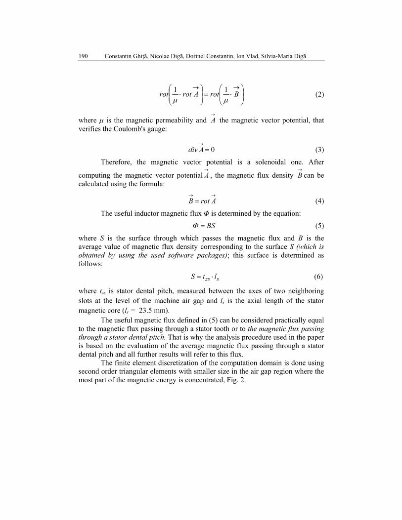
BS=Φ (5)
where S is the surface through which passes the magnetic flux and B is the average value of magnetic flux density corresponding to the surface S (which is obtained by using the used software packages); this surface is determined as follows:
szs ltS ⋅= (6)
where tzs is stator dental pitch, measured between the axes of two neighboring slots at the level of the machine air gap and ls is the axial length of the stator magnetic core (ls = 23.5 mm).
The useful magnetic flux defined in (5) can be considered practically equal to the magnetic flux passing through a stator tooth or to the magnetic flux passing through a stator dental pitch. That is why the analysis procedure used in the paper is based on the evaluation of the average magnetic flux passing through a stator dental pitch and all further results will refer to this flux.
The finite element discretization of the computation domain is done using second order triangular elements with smaller size in the air gap region where the most part of the magnetic energy is concentrated, Fig. 2.

Finite element analysis of the useful magnetic flux of a low speed PMSM 191
Fig. 2. Mesh on the computation domain and a detail of the mesh
corresponding to the marked area
4. Influence of geometric parameters on the useful magnetic flux
The useful magnetic flux of the motor depends on its cross-section geometry and on the material characteristics of the magnetic cores of the machine. The paper analyzes the influence of stator tooth width, slot isthmus opening, permanent magnet width and slot isthmus height on the useful magnetic flux. The influence of the material properties of the stator magnetic cores on the useful magnetic flux is also analyzed. To determine their influence, the magnetic flux density is calculated for each case using the 2D FEM model of the machine.
By solving the magnetostatic field problem associated to the studied motor we obtain the magnetic flux density chart and the spectrum of magnetic field lines as shown in Fig. 3.
After solving the magnetostatic 2D problem for different relative rotor/stator positions (by rotating incrementally the rotor armature) we found that maximum value of useful magnetic flux is obtained for an angle α = 3.53 ° [7] when the symmetry axis of the permanent magnet is aligned with the symmetry axis of the tooth (Fig. 2).

192 Constantin Ghiţă, Nicolae Digă, Dorinel Constantin, Ion Vlad, Silvia-Maria Digă
So if we calculate the average magnetic flux passing through the stator tooth, in 2D model rotor must be rotated so that the axis of symmetry of the permanent magnet is aligned with the symmetry axis of the tooth.
We can notice that the magnetic flux density differs from a tooth to another, its value depending on the tooth position with respect to the rotor permanent magnets. For this reason such a study should refer to a tooth situated in a position characterized by a maximum useful flux value.
Fig. 3. Spectrum of the PMSM inductor magnetic field lines and chart of magnetic flux density.
4.1. Influence of the stator tooth width
We can see in Fig. 1 that the motor has trapezoidal slots with rounded corners and the stator teeth have constant width and parallel walls. To study the influence of the stator tooth width bzs on the useful magnetic flux, we consider the tooth pitch constant. Thus if the tooth width is reduced by a certain size the slot width will increase by the same size.
The values for bzs cannot be chosen randomly, because very narrow teeth can lead to their excessive saturation and very large teeth can lead to an excessive increase of current density in the stator windings [5].
By solving successive 2D magnetostatic applications for various teeth widths we obtain the dependence of the useful magnetic flux on this parameter, Fig. 4.
By studying the results we can see that the useful magnetic flux increases by approximately 0.414 %, with the increase of the tooth width from 3.65 mm to 5.98 mm.
The same increase of the useful magnetic flux is obtained with the decrease of maximum magnetic flux density in the tooth from 1.8 T to 1.1 T, according to Fig. 5.

Finite element analysis of the useful magnetic flux of a low speed PMSM 193
Fig. 4. Useful magnetic flux versus stator teeth width bzs
Fig. 5. Useful magnetic flux versus maximum magnetic flux density in the tooth Bzs
0.209116
0.208253
Φ_t_zs
5.9823.656 b_zs3.5 3.81 4.13 4.44 4.75 5.06 5.38 5.69 6
0.2082
0.2083
0.2085
0.2086
0.2087
0.2088
0.209
0.2091
0.2092
Stator tooth width [mm]
Use
ful m
agne
tic fl
ux [m
Wb]
0.209116
0.208253
Φ_t_zs
1.81.1 B_zs1 1.1 1.2 1.3 1.4 1.5 1.6 1.7 1.8
0.2082
0.2083
0.2085
0.2086
0.2087
0.2088
0.209
0.2091
0.2092
Magnetic flux density in the tooth [T]
Use
ful m
agne
tic fl
ux [m
Wb]

194 Constantin Ghiţă, Nicolae Digă, Dorinel Constantin, Ion Vlad, Silvia-Maria Digă
4.2. Influence of the stator slot opening
The stator slot opening is noted with Bs0 in Fig. 1. To analyze the influence of this parameter on the useful magnetic flux zstΦ , because in our case Bs0=2 mm several values of this parameter are considered between 1.5 mm and 5.5 mm.
For each slot opening, the average magnetic flux zstΦ (the magnetic flux on a tooth pitch) is calculated, the results being presented in Fig. 6.
We can notice that the stator slot opening has a considerable influence on the inductor magnetic flux value. Thus, if the slot opening varies from 1.5 mm to 5.5 mm, the useful magnetic flux decreases by approximately 21,13 %. This decrease of the useful magnetic flux can be justified by the fact that the increase of slot opening entails a larger leakage magnetic flux and thus a smaller useful magnetic flux.
Fig. 6. Useful magnetic flux versus stator slot opening Bs0.
4.3. The influence of the permanent magnet width
To obtain concluding final results, the variation of the permanent magnet width was made by keeping constant the magnet cross-section area, i.e. by keeping constant the magnet volume. Thus if the magnet width decreases its thickness increases so as to keep unchanged the magnet cross-section area. The permanent magnet has the following characteristics: permanent magnet width, bm is variable in the range (13.5 mm ... 9 mm). By successive numerical simulations for various values of the magnet widths we obtained the results shown in Fig. 7 indicating an optimum of useful magnetic flux depending on the permanent magnet width. By studying these results we can see that the useful magnetic flux increases with the permanent magnet width bm to achieve the maximum value
0.212918
0.167921
Φ_t_zs_opening
5.51.5 Bs01 1.56 2.11 2.67 3.22 3.78 4.33 4.89 5.44 6
0.16
0.167
0.173
0.18
0.187
0.193
0.2
0.207
0.213
0.22
Stator slot opening [mm]
Use
ful m
agne
tic fl
ux [m
Wb]

Finite element analysis of the useful magnetic flux of a low speed PMSM 195
294.0=Φ zst mWb corresponding to a width of permanent magnet bm = 12 mm (Fig. 7). Thus, if the magnet width increases from 9 mm to 12 mm, the inductor magnetic flux increases by about 5.95 %. The reason for this increase is related to the magnetic flux path that in case of large width magnets it will be split on two or three teeth.
Fig. 7. Average useful magnetic flux versus permanent magnet width bm.
4.4. Influence of the stator slot isthmus height
The study carried out and presented further, took into account a variation of stator slot isthmus height within ± 30% from the reference value known Hs0 = 0.5 mm (resulting from traditional design, according to the literature, [6]). Thus to analyze the influence of this parameter on the useful magnetic flux Φ, are considered values of this parameter between 0.35 mm and 0.65 mm (Fig. 8).
Fig. 8. Useful magnetic flux versus stator slot isthmus height Hs0
0.294418
0.264835
Φ_t_zs
13.59 b_m_i9 9.63 10.25 10.88 11.5 12.13 12.75 13.38 14
0.26
0.265
0.27
0.275
0.28
0.285
0.29
0.295
0.3
Permanent magnet width [mm]
Use
ful m
agne
tic fl
ux [m
Wb]
0.29563
0.29274
Φ_t_zs_isthmus_height
0.650.35 Hs00.3 0.36 0.41 0.47 0.53 0.59 0.64 0.7
0.292
0.2926
0.2931
0.2937
0.2943
0.2949
0.2954
0.296
Stator slot isthmus height [mm]
Use
ful m
agne
tic fl
ux [m
Wb]

196 Constantin Ghiţă, Nicolae Digă, Dorinel Constantin, Ion Vlad, Silvia-Maria Digă
It is noted that the height of the stator slot isthmus has a relatively small influence on the value of inductor magnetic flux. Thus, if the height of the slot isthmus ranges from 0.35 mm to 0.65 mm, the useful inductor magnetic flux increases by about 0.987 %. This increase in the useful inductor magnetic flux can be justified by the fact that increasing the height of the slot isthmus implies a lower leakage magnetic flux and thus more useful magnetic flux.
5. Influence of current density in the stator winding
The study carried out and presented further, took into account a variation of the current density in the stator winding within -30% ... +15% compared to the reference value known js = 6 A/mm2 (resulting from traditional design, according to the literature [6]).
Fig. 9. Useful magnetic flux versus stator winding current density js
It is noted that the current density in the stator winding has a significant influence on the value of useful magnetic flux to the motor load operation. Thus, if the current density of the stator winding varies from 4.2 A/mm2 to 6.9 A/mm2 by successive numerical simulations for these values, we obtain the results shown in Fig. 9 which indicates an maximum (for js = 4.8 A/mm2) of useful magnetic flux depending on current density of the stator winding.
In the Fig. 9 were represented also the functions defined in Mathcad programming environment with which is approximated by spline interpolation (cspline, pspline, lspline) the curve raised through the points obtained through modelling and simulation.
By studying these results we can see that the useful magnetic flux increases with the current density in the stator winding js until to achieve the
0.26013
0.25286
sc a( )
sp a( )
sl a( )
Φ_t_zs_stator_current_density
6.94.2 a a, a, j_s,
4 4.3 4.6 4.9 5.2 5.5 5.8 6.1 6.4 6.7 70.252
0.253
0.254
0.255
0.256
0.257
0.258
0.259
0.26
0.261
0.262
Stator current density [A/mm2]
Use
ful m
agne
tic fl
ux [m
Wb]

Finite element analysis of the useful magnetic flux of a low speed PMSM 197
maximum value 0.26=Φ zst mWb corresponding to a current density in the stator winding js = 4.8 A/mm2 (Fig. 9). Thus, if the current density of the stator winding increases from 4.2 A/mm2 to 4.8 A/mm2, the useful magnetic flux increases by approximately 15 %. The reasons for this growth are several cumulated factors (including that one related to the magnetic flux path which in the case of magnets with large widths will be divided (split) for two or three teeth).
6. Conclusions
The FEM analysis carried out in this paper referred to a PMSM with a large number of poles that can used as an electric motor in the direct drive systems.
The research presented in the paper was focused on the influence analysis of several geometrical parameters of the machine (stator tooth width for the same stator tooth pitch and slot area, stator slots opening, permanent magnet width for the same magnet volume, stator slot isthmus height) on the useful inductor magnetic flux.
Also have been analyzed the influence of stator winding current density on the useful magnetic flux at the motor load operation.
From construction point of view the studied PMSM has a larger useful inductor magnetic flux in case of smaller slots openings, of larger teeth width (for the same tooth pitch), of wider permanent magnets (for the same magnet volume) and of larger slots isthmus heights.
The paper shows also the optimal ranges of these parameters for which the useful inductor magnetic flux is maximized. The maximization of the inductor magnetic flux leads to a more efficient use of the motor active materials making it more competitive on the market. The numerical results presented in the paper are useful for the functional-constructive optimization of PMSM.
Acknowledgement
The results presented in this research paper were obtained with the logistical support of S.C. INAS S.A. Craiova, Partnership-Collaboration Agreement no. PC 1527 of 17/03/2014.
The authors thank to the Board of Directors of S.C. INAS S.A. Craiova, Romania’s representative company ANSYS Inc., holder of licenses for software solutions distributor of CAD/CAM/CAE, which by Mr. General Manager Eng Constantin Ciolofan has directly supported in the development of a diverse range of applications, making it possible the functional-constructive optimization of the permanent magnet synchronous motor for driving a bicycle.

198 Constantin Ghiţă, Nicolae Digă, Dorinel Constantin, Ion Vlad, Silvia-Maria Digă
R E F E R E N C E S
[1] N. Bianchi, S. Bolognani and F. Luise, Analysis and design of a PM brushless motor for high-speed operations, IEEE Transactions on Energy Conversion, vol. 20, no. 3, pp. 629-637, September 2005.
[2] Ø. Krøvel, Design of Large Permanent Magnetized Synchronous Electric Machines, NTNU Trondheim - Norwegian University of Science and Technology, Faculty of Information Technology, Mathematics and Electrical Engineering, Department of Electric Power Engineering, Thesis for the degree of Philosophiae Doctor, February 2011.
[3] Ø. Krøvel, R. Nilssen, A. Nysveen, A Study of the Research Activity in the Nordic Countries on Large Permanent Magnet Synchronous Machines, NORPIE 2004.
[4] C. Schlensok, M. H. Gracia, K. Hameyer, Combined Numerical and Analytical Method for Geometry Optimization of a PM Motor, IEEE Transactions on Magnetics, Vol. 42, No. 4, April 2006, pp. 1211 – 1214.
[5] R. Măgureanu, N. Vasile, Brushless servomotors (in Romanian), Technical Press, Bucharest, Series Electrical machines and apparatus, 1990.
[6] K. A. Biro, I. A. Viorel, L. Syabo, G. Henneberger, Special electrical machines (in Romanian), MEDIAMIRA Press, Cluj-Napoca, 2005.
[7] N. Digă, C. Ghiţă, I. Vlad, S. M. Digă, and D. Constantin, Considerations on Modelling and Simulation of Stator Winding Distribution of a Permanent Magnet Synchronous Motor for Driving a Bicycle, XVIII-th International Symposium on Electrical Apparatus and Technologies SIELA 2014, 29-31 May 2014, Bourgas, Bulgaria, Poster Session P2, in Proceedings of Diggest, pp. 21-22, ISBN 978-619-160-320-6, Publishing House Avangard Prima, Sofia 2014, inclusion in IEEE Xplore®, 34347X the Conference ID.
[8] C. Ghiţă, Permanent regimes of electromechanical converters (in Romanian), MATRIX ROM Publishing House, Bucharest, 2008.
[9] C. Ghiţă, Steluţa Nedelcu, I. Trifu, T. Tudorache, Finite element analysis of the useful magnetic flux of a low speed PMSG., Scientific Bulletin of University POLITEHNICA of Bucharest, Series C, Vol. 75, Issue 1, pp. 239 – 250, 2013.
[10] S. M. Hwang, J. B. Eom, G. B. Hwang, W. B. Jeong, Y. H. Jung, Cogging torque and acoustic noise reduction in permanent magnet motors by teeth pairing, IEEE Transactions on Magnetics, Vol. 36, Issue 5, pp. 3144-3146 .
[11] J. B. Eom, S. M. Hwang, T. J. Kim, W. B. Jeong, B. S. Kan, Minimization of cogging torque in permanent magnet motors by teeth pairing and magnet arc design using genetic algorithm, Journal of Magnetism and Magnetic Materials, Vol. 226-230, Part 2, May 2001, pp. 1229-1231.
[12] C. C. Hwang, M. H. Wu, and S. P. Cheng, Influence of pole and slot combinations on cogging torque in fractional slot PM Motors, ELSEVIER, Journal of Magnetism and Magnetic Materials, 2006, pp. 430-432.
[13] L. Dosiek, F. Pillay, Cogging Torque Reduction in Permanent Magnet Machines, IEEE Transactions on Industry Applications, Vol. 43, No. 6, November/December 2007, pp. 1565-1571.
[14] B. Abdi, Cogging Torque Reduction in PM machines Used in Electro-Mechanical Battery, International Conference of Renewable Energy and Power Quality (ICREPQ'10), Granada, Spain, March 23 - 25, 2010, paper 260.
[15] T. Tudorache, L. Melcescu, M. Popescu, M. Cistelecan, Finite Element Analysis of Cogging Torque in Low Speed Permanent Magnets Wind Generator, International Conference of Renewable Energy and Power Quality (ICREPQ'08), Santander, Spain, March 12-14, 2008, paper 412.