finite element modeling of embolic coil deployment...
TRANSCRIPT

Finite element modeling of embolic coil deployment: Multifactorcharacterization of treatment effects on cerebralaneurysm hemodynamics
M. Haithem Babiker a,n, Brian Chong b, L. Fernando Gonzalez c, Sachmanik Cheema d,David H. Frakes a,d
a School of Biological and Health Systems Engineering, Arizona State University, 501 E. Tyler, ECG 334, P.O. Box 879709, Tempe, AZ 85287-9709, United Statesb Mayo Clinic Hospital, Phoenix, AZ, United Statesc Department of Neurological Surgery, Jefferson Medical College, Philadelphia, PA, United Statesd School of Electrical, Computer, and Energy Engineering, Arizona State University, Tempe, AZ, United States
a r t i c l e i n f o
Article history:Accepted 31 August 2013
Keywords:Computational fluid dynamicsFinite element modelEmbolic coilCerebral aneurysmPacking density
a b s t r a c t
Endovascular coiling is the most common treatment for cerebral aneurysms. During the treatment, asequence of embolic coils with different stiffness, shapes, sizes, and lengths is deployed to fill theaneurysmal sac. Although coil packing density has been clinically correlated with treatment success,many studies have also reported success at low packing densities, as well as recurrence at high packingdensities. Such reports indicate that other factors may influence treatment success. In this study, we useda novel finite element approach and computational fluid dynamics (CFD) to investigate the effects ofpacking density, coil shape, aneurysmal neck size, and parent vessel flow rate on aneurysmalhemodynamics. The study examines a testbed of 80 unique CFD simulations of post-treatment flowsin idealized basilar tip aneurysm models. Simulated coil deployments were validated against in vitro andin vivo deployments. Among the investigated factors, packing density had the largest effect on intra-aneurysmal velocities. However, multifactor analysis of variance showed that coil shape can also haveconsiderable effects, depending on packing density and neck size. Further, linear regression analysisshowed an inverse relationship between mean void diameter in the aneurysm and mean intra-aneurysmal velocities, which underscores the importance of coil distribution and thus coil shape. Ourstudy suggests that while packing density plays a key role in determining post-treatment hemody-namics, other factors such as coil shape, aneurysmal geometry, and parent vessel flow may also be veryimportant.
& 2013 Elsevier Ltd. All rights reserved.
1. Introduction
Cerebral aneurysms are pathological, sac-like dilations of bloodvessel walls in the brain that commonly occur at major branchpoints in the Circle of Willis (Brisman et al., 2006). When acerebral aneurysm ruptures, the subsequent damage is lethal in45% of cases (Bederson et al., 2009). Accordingly, it is criticallyimportant to treat cerebral aneurysms effectively either before orvery shortly after rupture. Endovascular coiling is the mostcommon treatment both before and after rupture (Lin et al.,2011). The treatment consists of deploying a sequence of emboliccoils of different shapes and sizes into the aneurysmal sac, withthe intent of filling the sac and thereby reducing aneurysmal
inflow. Reducing aneurysmal inflow may initiate subsequentthrombosis within the sac, leading to occlusion of the aneurysmand its eventual exclusion from circulation, which is one definitionof a successful treatment outcome (Piotin et al., 2007). Otherfactors, including coil material, may also influence aneurysmalthrombosis (White et al., 2008b).
To facilitate effective endovascular coiling, physicians typicallytarget a high packing density (defined as the percentage of theaneurysmal volume occupied by coils). A wide range of coils withdifferent stiffness, lengths, shapes, and sizes can be added to thedeployment sequence in order to achieve that goal among others(e.g., coil stability). The coils are constructed from a thin metalwire that is wound into a secondary helical structure as shown inFig. 1a, which is then shaped into a tertiary structural configura-tion. Coils can have many different tertiary structures or “shapes”.The two most common are helical and complex, which areillustrated in Fig. 1b. Helical coil structures take the form of a
Contents lists available at ScienceDirect
journal homepage: www.elsevier.com/locate/jbiomechwww.JBiomech.com
Journal of Biomechanics
0021-9290/$ - see front matter & 2013 Elsevier Ltd. All rights reserved.http://dx.doi.org/10.1016/j.jbiomech.2013.08.021
n Corresponding author. Tel.: þ1 347 495 6156; fax: þ1 917 591 8336.E-mail address: [email protected] (M.H. Babiker).
Journal of Biomechanics 46 (2013) 2809–2816

helix, while complex structures take on a spherical shape. Coilshape and shape size (D3 in Fig. 1a) influence aneurysmal fillingand coil distribution in the sac, while the thickness of the metalwire (D1 in Fig. 1a) and the diameter of the helical wind (D2 inFig. 1a) determine coil stiffness (White et al., 2008a).
Packing density is currently the only coil deployment para-meter that has been clinically correlated with aneurysmal occlu-sion. However, many studies have reported occlusion at lowpacking densities and recurrence at high packing densities(Piotin et al., 2007). Such reports indicate that other factors,including coil distribution, may influence treatment success.Specific effects remain poorly understood, however, due in partto limitations of in-vivo flow measurement techniques in thecontext of coiled aneurysms.
Previous in vitro studies have quantified hemodynamics incoiled aneurysms, but have been subject to considerable limita-tions. For example, in vitro studies have not investigated the role ofcoil distribution on post-treatment hemodynamics and have onlyconsidered a small, usually statistically insignificant, number ofcases because of the costs associated with embolic coil experi-ments (Babiker et al., 2010; Sorteberg et al., 2004). Conversely, insilico studies have simulated many coiled cases but have relied onunrealistic assumptions to simplify complex coil geometries. Forexample, coils have been modeled as a homogenous porous media,as a single sphere inside the aneurysmal sac, as perfectly helicaltubes, and as cylinders with random trajectories inside the sac(Mitsos et al., 2007; Byun and Rhee, 2004; Schirmer et al., 2010;Morales et al., 2011).
We present an in silico study that uses a novel finite element(FE) approach and computational fluid dynamics (CFD) to simulatepost-treatment hemodynamics in idealized models of basilar tipaneurysms. The FE approach considers the physical properties ofcoils and applies structural dynamics to simulate coil deployment.The approach is used to evaluate the influence of coil shape,aneurysmal neck size, packing density, and parent vessel flow onpost-treatment hemodynamics in a testbed of 80 unique cases.This study represents the first time, to the authors' knowledge,that deployment mechanics and the physical properties of coilshave been considered in studying the post-treatment hemody-namics of coiled aneurysms.
2. Methods
2.1. Model construction
Two idealized computational models of basilar tip aneurysms were designed inSolidworks (SolidWorks, Concord, MA): a narrow-neck (nneck) and wide-neck(wneck) model with dome-to-neck-width ratios of 1.5 and 1.1, respectively. Thedimensions of both models are presented in Fig. 2. The dome-to-neck-width ratioswere chosen to represent different types of aneurysm cases commonly
encountered in the clinic: a narrow-neck case that would be considered fortreatment with coils alone and a wide-neck case that requires either a stent orballoon during treatment (Brinjikji et al., 2009).
2.2. Modelling virtual coil deployment
Embolic coils were modeled using three-dimensional (3D) beam theory, whichis similar to the approach used by Dequidt et al. (2009). Each coil was representedby a set of serially linked 3D Timoshenko beam elements in Abaqus (Simulia,Providence, RI). The beam elements were assumed to be elastic with 92% platinumand 8% tungsten material composition (White et al., 2008a), which resulted in anelastic modulus of 7.5 GPa and a density of 21.3 g/cm3. A Poisson ratio of 0.39 wasalso prescribed after approximating the coils as solid beams composed primarily ofplatinum. This simplification followed the assumption that the coil stock wire wastightly and perfectly wound and that individual helical winds could not bestretched. Further, the cross-sectional plane of the beam element was assumedto remain plane and undistorted during deployment.
Two coils were modeled: A long framing coil with an 8 cm length and a0.31 mm diameter (D2), and a shorter coil with a 2 cm length and a 0.27 mmdiameter. The coils were virtually placed in a 0.4 mm diameter rigid microcatheterand a rigid ellipsoidal balloon was used to constrain coils within the aneurysmalsac during deployment, which is similar to the balloon-assisted technique usedin vivo. The balloon was modeled according to the shape of the physical balloonused in previous in vitro experiments conducted by our group (Babiker et al., 2010),which facilitated comparisons between computational and experimental results.More detail on the balloon is provided in the Appendix.
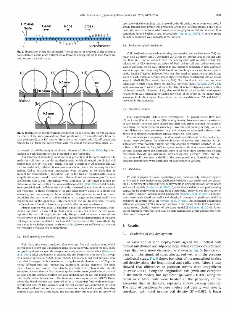
The coils were discretized with a mesh resolution of 1:5� D2; finer meshresolutions resulted in considerable overclosure between adjacent coil loops.Parametric equations were applied through a subroutine to specify coil shapeand loop size; concentrated load forces were exerted on the beam element nodes ineach Cartesian direction, as shown in Fig. 3. The parametric equations were derivedby estimating the force required to displace a beam element by D3=2 and scaling/applying that force to the set of beam elements using a non-uniform distributionthat modeled coil shape. Two non-uniform distributions were modeled: a complexand a helical distribution. The complex distribution was modeled as a 3D curvewith multiple helical loops rotated around a sphere at different angles, which issimilar to the physical geometries of complex coils as described in Hung et al.(2005). The helical distribution was simply modeled as helical loops perpendicular
Fig. 1. Illustration of coil structural characteristics showing the metal wire diameter D1 (ranges from 0.00175 to 0.003 in), the helical wind diameter D2 (ranges from 0.010 to0.020 in), and the diameter of the tertiary shape D3 (a). Examples of helical and complex tertiary coil shapes (b).
Fig. 2. Nneck (a) and wneck (b) model dimensions. Detail on model constructioncan be found in Babiker et al. (2010).
M.H. Babiker et al. / Journal of Biomechanics 46 (2013) 2809–28162810
to the main axis of the straight set of beam elements (Lubicz et al., 2004). Equationsrelating to both distributions are presented in the Appendix.
A displacement boundary condition was prescribed at the proximal node toguide the coil into the sac during deployment, which simulated the clinical coilpusher tool used in vivo. The ”general contact” algorithm in Abaqus/Explicit wasused to model self, coil-to-coil, coil-to-microcatheter, and coil-to-aneurysm inter-actions. Coil-to-microcatheter interactions were assumed to be frictionless toaccount for microcatheter lubrication. Due to the lack of reported data, severalsimplifications were used to estimate coil-to-coil and coil-to-aneurysm frictionalcoefficients. Coil-to-coil interactions were simplified as lubricated platinum-to-platinum interactions with a frictional coefficient of 0.2 (Dorf, 2004). A 0.4 coil-to-aneurysm frictional coefficient was indirectly calculated by matching simulated coilslip velocities to those measured in in vivo angiography videos of a single coiladvancing into an aneurysm. More detail on that process as well as resultsdescribing the sensitivity of coil mechanics to changes in frictional coefficientscan be found in the Appendix. Only changes in the coil-to-aneurysm frictionalcoefficient were found to have an appreciable effect on coil mechanics.
Abaqus Explicit was used to simulate a five-coil deployment sequence com-prising one 4 mm �8 cm coil and four 2 mm �2 cm coils, where the two valuesrepresent D3 and coil length, respectively. The proximal node was advanced intothe aneurysm at a fixed speed of 4.5 mm/s. Five different deployments of the samecoil sequence were simulated in each model. The position of the microcatheter tipwas varied in each deployment, as shown in Fig. 4, to ensure sufficient variations inthe resulting deployed coil configurations.
2.3. Fluid dynamics simulations
Fluid dynamics were simulated after one and five coil deployments, whichcorresponded to 19% and 33% packing densities, respectively, in both models. Thosetwo packing densities span the range commonly achieved in the clinic (Kawanabeet al., 2001). After deployment in Abaqus, the coil beam elements were first sweptby a circular surface in ANSYS ICEM (ANSYS, Canonsburg, PA). Coil surfaces werethen shrinkwrapped with a maximum triangular mesh element size of 20 μm tomerge different coils and remove any intersecting surface elements. The smallmesh element size ensured that structural details were retained after shrink-wrapping. A mesh density function was applied to the aneurysmal volume and coilsurfaces and the Octree algorithm was used to discretize the coil and blood volumeinto 19–25 million tetrahedrons. The final mesh was imported into ANSYS Fluentwhere the blood volume was assumed to be a Newtonian fluid with 1060 kg/m3
density and 0.00371 Pa s viscosity, and the coil volume was assumed to be solid.The vessel wall and coil surfaces were assumed to be rigid and a no-slip boundarycondition was applied at the walls. The SIMPLE algorithm was used to specify the
pressure–velocity coupling, and a second-order discretization scheme was used. Asteady laminar flow profile was prescribed at the inlet of each model. 3 and 5 ml/sflow rates were examined, which correspond roughly to normal and diseased flowconditions in the basilar artery, respectively (Jou et al., 2007). A zero pressureboundary condition was imposed at the outlets.
2.4. Evaluation of coil distribution
Coil distribution was evaluated using two metrics: coil surface area (CSA) andmean void diameter (MVD). We define CSA as the coil surface area in contact withthe fluid (i.e., not in contact with the aneurysmal wall or other coils). Thecalculation of CSA involved exclusion of both coil-to-coil and coil-to-aneurysmsurface contacts, which was inherent to our meshing approach. A new approachwas developed for measuring MVD based on inscribing circles within aneurysmalvoids. Tecplot (Tecplot, Bellevue, WA) was first used to generate multiple imageslices of each coiled aneurysm. Image slices were then constructed into an imagearray in MATLAB (Mathworks, Natick, MA). Next, local void size maxima werecalculated in each image based on artificial potential fields (LaValle, 2006). Thelocal maxima were used to calculate the largest non-overlapping circles, with aminimum possible diameter of D2, that could be inscribed within void spaces.Finally, MVD was calculated by taking the mean of all circles in the image array,across multiple dimensions. More detail on the calculation of CSA and MVD isprovided in the Appendix.
2.5. Statistical analysis
Four experimental factors were investigated: (A) parent vessel flow rate,(B) neck size, (C) coil shape, and (D) packing density. Two levels were investigatedin each factor. The levels were chosen such that they either spanned the ranges ofeach factor encountered in the clinic (e.g., flow rate and packing density), varied acontrollable treatment parameters (e.g., coil shape), or examined different cate-gories of commonly encountered clinical cases (e.g., neck-size).
Five simulations, comprising the aforementioned different deployment orien-tations, were performed for each combination of factors. The resulting 80 CFDsimulations were evaluated using two-way analysis of variance (ANOVA) in JMPsoftware (SAS Institute, Cary, NC). Analysis considered three response variables: thepercent changes (from the untreated case) in (i) mean intra-aneurysmal velocitymagnitude (MVM), (ii) maximum intra-aneurysmal pressure (MIP), and (iii)maximum wall shear stress (MWSS) at the aneurysmal neck. Normality and equalvariance assumptions were examined for each response variable.
2.6. Validation
FE coil deployments were qualitatively and quantitatively validated againstin vitro and in vivo deployments. Qualitative validation was performed by compar-ing FE deployments against in vitro deployments in physical versions of the nneckand wneck models (Babiker et al., 2010). Quantitative validation was performed bycomparing FE deployments to data from a histological study on coil distribution in10 elastase-induced saccular rabbit aneurysms (Morales et al., in press). Compar-isons were made based on in-slice coil density in aneurysmal partitions, which isexplained in greater detail in Morales et al. in press. An additional quantitativevalidation compared CFD simulations of flow in the nneck model to PIV measure-ments from a physical version of the same model (Babiker et al., 2010). Parentvessel centerline velocities and RMS velocity magnitudes at the aneurysmal neck-plane were compared.
3. Results
3.1. Validation of coil deployment
In silico and in vitro deployments agreed well; helical coilsformed intertwined and adjacent loops, while complex coils formedloops that were more dispersed, as shown in Fig. 5. In-slice coildensity in the simulated cases also agreed well with the previoushistological study. Fig. 6 shows box plots of the normalized in-slicecoil density along the longitudinal and radial axes. Paired t-testsshowed that differences in partition means were insignificantðp�value40:12Þ along the longitudinal axis (with one exceptionin the nneck model), but significant ðp�valueo0:001Þ along theradial axis. More coils were located at the periphery of theaneurysm than at the core, especially at low packing densities.The ratio of peripheral to core in-slice coil density was linearlycorrelated with total in-slice coil density (R2 ¼ 0:68). A linear
Fig. 3. Illustration of the FE coil model. The coil pusher is modeled at the proximalnode (defined as the node furthest away from the aneurysm) while load forces areused to prescribe coil shape.
Fig. 4. Illustration of the different microcatheter tip positions. The tip was placed atthe center of the aneurysmal dome (base position) (i), 0.5 mm off-center from thebase position (ii), at a 15○ rotation from the parent vessel axis (iii), off-center androtated by 15○ from the parent vessel axis (iv), and at the aneurysmal neck (v).
M.H. Babiker et al. / Journal of Biomechanics 46 (2013) 2809–2816 2811

regression projected that the ratio reaches unity at a total in-slicecoil density of 36.5%. Overall, the results concur with conclusionsdrawn in the histological study (Morales et al., in press).
Simulated neck-plane RMS velocity magnitudes also agreedvery well with previously acquired PIV data, as shown in Fig. 7.Further, parent vessel centerline velocity profiles in the simulatedcases were consistent with velocity profiles from the PIV-
measured cases in terms of linearity and mean slope, as shownin Fig. 8.
3.2. Effects of experimental factors: ANOVAs
Normal probability plots confirmed the normality of thecalculated response variables. However, a two-sided F-test showed
Fig. 5. Deployment of a helical coil in the nneck computational (a) and physical (b) models. A complex coil deployment is also shown in the wneck computational (c) andphysical (d) models.
Fig. 6. Boxplots of normalized in-slice coil densities calculated per partition along the longitudinal and radial axes in the nneck (a) and wneck (b) models.
M.H. Babiker et al. / Journal of Biomechanics 46 (2013) 2809–28162812

unequal variances between response variables at low and highpacking densities (p�value¼ 0:0024). Accordingly, a multifactorANOVA was performed for each packing density and non-pooledt-tests were used to test significance between packing densities.Results from both ANOVAs are presented in Table 1, and the effectsof investigated factors on MVM are presented in Fig. 9.
3.2.1. Packing densityAmong the investigated factors, packing density had the great-
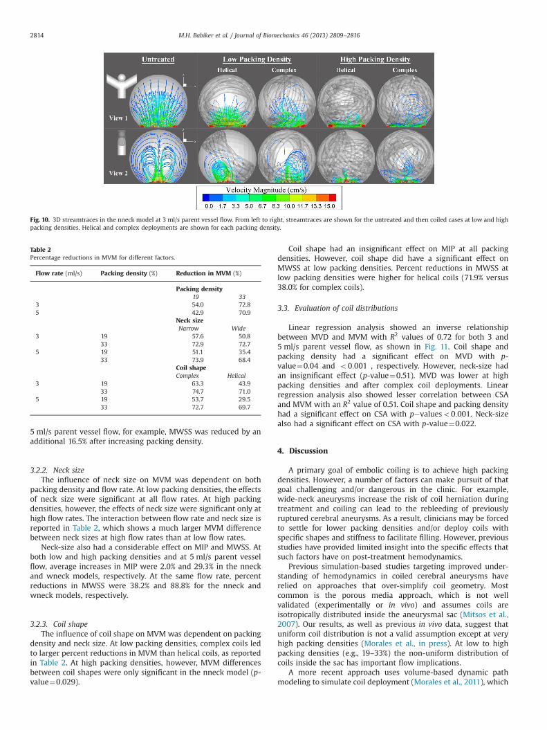
est effect on MVM, as illustrated by the streamtraces in Fig. 10.Table 2 confirms the finding; larger MVM differences wereobserved between packing densities than between other factorlevels. Increasing packing density also reduced standard deviationsin MVM by an average of 46.9% over the two models.
MIP was also significantly affected by packing density(p�valueo0:001). Percent increases in MIP at low packing den-sities were 3.0% and 15.9% at 3 and 5 ml/s parent vessel flow,respectively. However, increasing packing density led to a small1.6%–3.5% additional increase in MIP. Increases in packing densityhad a larger effect on MWSS though. In the wneck model and at
Fig. 7. CFD-simulated and PIV-measured neck-plane RMS velocity magnitudeðm=sÞ vs. coil packing density (%).
Fig. 8. X-direction component of flow velocity (dimensionalized against maximumparent vessel velocity) along the model centerline versus X-direction distance(dimensionalized against parent vessel diameter) from the neck-plane at 5 ml/sparent vessel flow. The decline in centerline velocity was linear at a distance of 0.31from the neck-plane, with mean slopes of 1.74 and 1.92 at a 19% and 33% packingdensities (PD) in the simulated cases, respectively. PIV-measured slopes were 1.57and 1.87 for the same packing densities, respectively.
Table 1P-values from the two-way multi-factor ANOVAs at low and high packing densities. Values are reported only for significant factors.
Low packing densities High packing densities
Factor MVM MIP MWSS MVM MIP MWSS
Flow rate 0.011 o0:001 o0:001 o0:001 o0:001Neck size 0.032 o0:001 o0:001 o0:001 0.031Coil design o0:001 o0:001Flow rate*Neck size o0:001 o0:001 0.045 o0:001Neck size*Coil design o0:001 o0:001Flow rate*Neck size*Coil design o0:001
Fig. 9. Reductions in MVM (%) within the aneurysmal sac at 3 ml/s (a) and 5 ml/s(b) parent vessel flow rates. Percentage values on the vertical axis representvelocity magnitude reduction with respect to the untreated case.
M.H. Babiker et al. / Journal of Biomechanics 46 (2013) 2809–2816 2813
5 ml/s parent vessel flow, for example, MWSS was reduced by anadditional 16.5% after increasing packing density.
3.2.2. Neck sizeThe influence of neck size on MVM was dependent on both
packing density and flow rate. At low packing densities, the effectsof neck size were significant at all flow rates. At high packingdensities, however, the effects of neck size were significant only athigh flow rates. The interaction between flow rate and neck size isreported in Table 2, which shows a much larger MVM differencebetween neck sizes at high flow rates than at low flow rates.
Neck-size also had a considerable effect on MIP and MWSS. Atboth low and high packing densities and at 5 ml/s parent vesselflow, average increases in MIP were 2.0% and 29.3% in the nneckand wneck models, respectively. At the same flow rate, percentreductions in MWSS were 38.2% and 88.8% for the nneck andwneck models, respectively.
3.2.3. Coil shapeThe influence of coil shape on MVM was dependent on packing
density and neck size. At low packing densities, complex coils ledto larger percent reductions in MVM than helical coils, as reportedin Table 2. At high packing densities, however, MVM differencesbetween coil shapes were only significant in the nneck model (p-value¼0.029).
Coil shape had an insignificant effect on MIP at all packingdensities. However, coil shape did have a significant effect onMWSS at low packing densities. Percent reductions in MWSS atlow packing densities were higher for helical coils (71.9% versus38.0% for complex coils).
3.3. Evaluation of coil distributions
Linear regression analysis showed an inverse relationshipbetween MVD and MVM with R2 values of 0.72 for both 3 and5 ml/s parent vessel flow, as shown in Fig. 11. Coil shape andpacking density had a significant effect on MVD with p-value¼0.04 and o0:001 , respectively. However, neck-size hadan insignificant effect (p-value¼0.51). MVD was lower at highpacking densities and after complex coil deployments. Linearregression analysis also showed lesser correlation between CSAand MVM with an R2 value of 0.51. Coil shape and packing densityhad a significant effect on CSA with p�valueso0:001. Neck-sizealso had a significant effect on CSA with p-value¼0.022.
4. Discussion
A primary goal of embolic coiling is to achieve high packingdensities. However, a number of factors can make pursuit of thatgoal challenging and/or dangerous in the clinic. For example,wide-neck aneurysms increase the risk of coil herniation duringtreatment and coiling can lead to the rebleeding of previouslyruptured cerebral aneurysms. As a result, clinicians may be forcedto settle for lower packing densities and/or deploy coils withspecific shapes and stiffness to facilitate filling. However, previousstudies have provided limited insight into the specific effects thatsuch factors have on post-treatment hemodynamics.
Previous simulation-based studies targeting improved under-standing of hemodynamics in coiled cerebral aneurysms haverelied on approaches that over-simplify coil geometry. Mostcommon is the porous media approach, which is not wellvalidated (experimentally or in vivo) and assumes coils areisotropically distributed inside the aneurysmal sac (Mitsos et al.,2007). Our results, as well as previous in vivo data, suggest thatuniform coil distribution is not a valid assumption except at veryhigh packing densities (Morales et al., in press). At low to highpacking densities (e.g., 19–33%) the non-uniform distribution ofcoils inside the sac has important flow implications.
A more recent approach uses volume-based dynamic pathmodeling to simulate coil deployment (Morales et al., 2011), which
Fig. 10. 3D streamtraces in the nneck model at 3 ml/s parent vessel flow. From left to right, streamtraces are shown for the untreated and then coiled cases at low and highpacking densities. Helical and complex deployments are shown for each packing density.
Table 2Percentage reductions in MVM for different factors.
Flow rate (ml/s) Packing density (%) Reduction in MVM (%)
Packing density19 33
3 54.0 72.85 42.9 70.9
Neck sizeNarrow Wide
3 19 57.6 50.833 72.9 72.7
5 19 51.1 35.433 73.9 68.4
Coil shapeComplex Helical
3 19 63.3 43.933 74.7 71.0
5 19 53.7 29.533 72.7 69.7
M.H. Babiker et al. / Journal of Biomechanics 46 (2013) 2809–28162814

is more geometry-based, but in no way accounts for the physicalproperties of coils or for realistic deployment mechanics. Incontrast, the proposed FE approach is based directly on coilproperties, design specifications, and deployment mechanics.Qualitative and quantitative validations showed strong agreementbetween FE deployments and previous in vitro and in vivo deploy-ments. Further, post-treatment hemodynamic simulations showedexcellent agreement with PIV measurements of flow within amatching and identically packed physical model.
4.1. Comparison with in vitro results
Simulation results agreed well with the conclusions of aprevious in vitro study conducted by our group (Babiker et al.,2010). First, packing density had the largest effect on post-treatment fluid dynamics. Under all conditions, increasing packingdensity led to larger reductions in MVM than changing coil shapeor parent vessel flow. Second, coiling was most effective innarrow-neck aneurysms. Percentage reductions in MVM wereconsistently larger in the nneck model, especially at high parentvessel flow rates. This result also agrees with clinical reports of
lower treatment success rates for wider-neck aneurysms(Raymond et al., 2003). One way to improve those success ratesmay be to initiate treatment using a first coil with a wide helicalwind diameter (i.e., larger D2) so as to achieve high packingdensities before problems with dense multi-coil packing (e.g. coilherniation) can become a problem. Lastly, percentage reductionsin MVM were lesser at higher parent vessel flow rates, whichsuggests that patients with high parent vessel flow rates (e.g.hypertensive or diseased cases) may be at greater risk aftertreatment. Accordingly, measures taken to monitor blood flowconditions after treatment may be important for post-operative care.
4.2. Coil distribution
Simulation results shed new light on the effects that coildistribution has on post-treatment hemodynamics. Coil distribu-tion had a larger influence on post-treatment hemodynamics atlow packing densities. This finding is supported by the statisticalsignificance of coil shape and the large variations in MVMobserved at low packing densities, which were four times greaterthan for high packing densities. It is noteworthy that at highpacking densities, coil shape was statistically significant only inthe nneck model. We attribute this result to the larger dome-height of the nneck model, which allowed coils to take on morediverse post-deployment configurations.
Results from our investigation of coil distribution also showed astrong relationship between MVD (an indicator of average aneur-ysmal pore size) and percent reductions in MVM. As MVDdecreased, coils became more uniformly distributed inside theaneurysm and dissipated flow jets from the parent vessel to agreater degree. Results showed that the most effective measure toreduce MVD was increasing packing density. However, coil shapewas also important; complex coils resulted in lower MVD becausetheir coil loops were more dispersed (as compared to helical coils).Accordingly, we propose that coil shape not only has potential toaffect aneurysmal filling, but can also be important for favorablepost-treatment hemodynamics. Choosing the correct coil shape isespecially critical when high packing densities cannot be reached,which is a common problem during the treatment of manycomplex aneurysms (Tateshima et al., 2000).
4.3. Pressure and wall shear stress
Intra-aneurysmal pressure and WSS were primarily influencedby neck size and parent vessel flow rate. Packing density mini-mally influenced intra-aneurysmal pressure, but did effect WSS atthe aneurysmal neck. Specifically, increasing packing density led toconsiderable reductions in MWSS at the neck.
4.4. Conclusion
We presented a novel FE approach for simulating post-treatment hemodynamics in coiled cerebral aneurysms. Resultsfrom our coil deployment validation agreed well with in vitro andin vivo data. Results from post-treatment CFD simulations showedthat packing density had a large effect on post-treatment hemo-dynamics, but that coil distribution (and thus coil shape), as wellas aneurysmal neck size, also had important effects at certainpacking densities.
4.5. Limitations and future work
Several limitations of this study are noteworthy. First, emboliccoils were simplified as solid beam elements. While this simpli-fication reduced computational cost and resulted in realistic coil
Fig. 11. Reductions in MVM (%) within the aneurysmal sac versus MVD for 3 ml/s(a) and 5 ml/s (b) parent vessel flows. Results of linear regression on the data points(black dots) are represented by the solid lines. Dashed lines are the limits of the95% confidence intervals.
M.H. Babiker et al. / Journal of Biomechanics 46 (2013) 2809–2816 2815

deployments (as supported by our multiple validations), it mayoverestimate the stiffness of coils and underestimate their pro-pensity to stretch longitudinally. Second, contact interactions weresimplified as wire-to-wire or node-to-wire contacts during FE coildeployment. Third, we have focused only on idealized models.Fourth, the microcatheter was fixed during FE deployments, andrigid walls were assumed in both FE and CFD simulations. Theseassumptions greatly simplified simulations, allowing us to conducta large number of trials. However, the rigid wall assumption maycontribute to overestimated intraaneurysmal velocities and affectcoil deployment mechanics to a degree. Fifth, only steady stateflow conditions were examined. However, our past experiencewith the idealized geometries used in this study suggests thatsteady state conditions provide good indications of flow trendsthat result under pulsatile conditions (Babiker et al., 2012). Futurework will validate the frictional coefficients used in this study,examine patient-specific aneurysm models, investigate pulsatileflow conditions, consider more realistic structural dynamics andcontact interactions in both FE deployments and CFD simulations,and explore opportunities for greater computational efficiency.
Conflict of interest statement
The authors declare that there are no conflicts of interestassociated with this publication.
Acknowledgments
The authors acknowledge funding from the National ScienceFoundation CAREER Award, the ASU/Mayo Clinic Arizona SeedGrant, the Brain Aneurysm Foundation Research Grant, and theAmerican Heart Association Beginning Grant-in-Aid. The authorswould also like to thank Codman Neurovascular (Raynham, MA,USA) and ev3 (Plymouth, MN, USA) for the embolic coils, balloons,and catheters used in developing our FE models.
Appendix A. Supplementary material
Supplementary data associated with this article can be foundin the online version of http://dx.doi.org/10.1016/j.jbiomech.2013.08.021.
References
Babiker, M.H., Gonzalez, L.F., Albuquerque, F., Collins, D., Elvikis, A., Frakes, D.H.,2010. Quantitative effects of coil packing density on cerebral aneurysm fluiddynamics: an in vitro steady flow study. Annals of Biomedical Engineering 38,2293–2301.
Babiker, M.H., Gonzalez, L.F., Ryan, J., Albuquerque, F., Collins, D., Elvikis, A., Frakes,D.H., 2012. Influence of stent configuration on cerebral aneurysm fluiddynamics. Journal of Biomechanics 45, 440–447.
Bederson, J.B., Connolly, E.S., Batjer, H.H., Dacey, R.G., Dion, J.E., Diringer, M.N.,Duldner, J.E., Harbaugh, R.E., Patel, A.B., Rosenwasser, R.H., 2009. Guidelines forthe management of aneurysmal subarachnoid hemorrhage: a statement forhealthcare professionals from a special writing group of the stroke council,American Heart Association. Stroke 40, 994–1025.
Brinjikji, W., Cloft, H., Kallmes, D., 2009. Difficult aneurysms for endovasculartreatment: overwide or undertall? American Journal of Neuroradiology 30,1513–1517.
Brisman, J., Song, J., Newell, D., 2006. Cerebral aneurysms. New England Journal ofMedicine 355, 928–939.
Byun, H.S., Rhee, K., 2004. CFD modeling of blood flow following coil embolizationof aneurysms. Medical Engineering & Physics 26, 755–761.
Dequidt, J., Duriez, C., Cotin, S., Kerrien, E., 2009. Towards interactive planning ofcoil embolization in brain aneurysms. In: Medical Image Computing andComputer-Assisted Intervention MICCAI 2009. Springer Berlin Heidelberg,Berlin, Heidelberg. vol. 5761, pp. 377–385.
Dorf, R.C., 2004. CRC Handbook of Engineering Tables. CRC Press, Boca Raton, FL.Hung, R.K., Loh, C., Goldstein, L., 2005. Selective use of electrolytic detachable and
fibered coils to embolize a wide-neck giant splenic artery pseudoaneurysm.Journal of Vascular Surgery 41, 889–892.
Jou, L., Mohamed, A., Lee, D., Mawad, M., 2007. 3D rotational digital subtractionangiography may underestimate intracranial aneurysms: findings from twobasilar aneurysms. American Journal of Neuroradiology 28, 1690–1692.
Kawanabe, Y., Sadato, A., Taki, W., Hashimoto, N., 2001. Endovascular occlusion ofintracranial aneurysms with Guglielmi detachable coils: correlation betweencoil packing density and coil compaction. Acta Neurochirurgica 143, 451–455.
LaValle, S., 2006. Planning Algorithms. Cambridge University Press.Lin, N., Cahill, K.S., Frerichs, K.U., Friedlander, R.M., Claus, E.B., 2011. Treatment of
ruptured and unruptured cerebral aneurysms in the USA: a paradigm shift.Journal of NeuroInterventional Surgery 4, 182–189.
Lubicz, B., Leclerc, X., Gauvrit, J.Y., Lejeune, J.P., Pruvo, J.P., 2004. Selectiveendovascular treatment of intracranial aneurysms with sapphire coils. Amer-ican Journal of Neuroradiology 25, 1368–1372.
Mitsos, A.P., Kakalis, N., Ventikos, Y.P., Byrne, J.V., 2007. Haemodynamic simulationof aneurysm coiling in an anatomically accurate computational fluid dynamicsmodel: technical note. Neuroradiology 50, 341–347.
Morales, H.G., Kim, M., Vivas, E.E., Villa-Uriol, M.C., Larrabide, I., Sola, T., Guimar-aens, L., Frangi, A.F., 2011. How do coil configuration and packing densityinfluence Intra-Aneurysmal hemodynamics? American Journal of Neuroradiol-ogy 32, 1935–1941.
Morales, H.G., Larrabide, I., Geers, A.J., Dai, D., Kallmes, D.F., Frangi, A.F. Analysis andquantification of endovascular coil distribution inside saccular aneurysms usinghistological images. Journal of NeuroInterventional Surgery, http://dx.doi.org/10.1136/neurintsurg-2012-010456,in press.
Piotin, M., Spelle, L., Mounayer, C., Salles-Rezende, M.T., Giansante-Abud, D.,Vanzin-Santos, R., Moret, J., 2007. Intracranial aneurysms: treatment with bareplatinum CoilsAneurysm packing, complex coils, and angiographic recurrence.Radiology 243, 500–508.
Raymond, J., Guilbert, F., Weill, A., Georganos, S., Juravsky, L., Lambert, A.,Lamoureux, J., Chagnon, M., Roy, D., 2003. Long-term angiographic recurrencesafter selective endovascular treatment of aneurysms with detachable coils.Stroke 34, 1398–1403.
Schirmer, C.M., Malek, A.M., 2010. Critical influence of framing coil orientation onIntra-Aneurysmal and neck region hemodynamics in a sidewall aneurysmmodel. Neurosurgery 67, 1692–1702.
Sorteberg, A., Sorteberg, W., Aagaard, B., Rappe, A., Strother, C., 2004. Hemody-namic versus hydrodynamic effects of Guglielmi detachable coils on intra-aneurysmal pressure and flow at varying pulse rate and systemic pressure.American Journal of Neuroradiology 25, 1049–1057.
Tateshima, S., Murayama, Y., Gobin, Y.P., Duckwiler, G.R., Guglielmi, G., Viuela, F.,2000. Endovascular treatment of basilar tip aneurysms using Guglielmidetachable coils: anatomic and clinical outcomes in 73 patients from a singleinstitution. Neurosurgery 47, 1332–1342.
White, J., Ken, C., Cloft, H., Kallmes, D., 2008a. Coils in a nutshell: a review of coilphysical properties. American Journal of Neuroradiology 29, 1242–1246.
White, P., Raymond, J., Raymond, J., 2008b. Endovascular coiling of cerebralaneurysms using “Bioactive” or coated-coil technologies: a systematic reviewof the literature. American Journal of Neuroradiology 30, 219–226.
M.H. Babiker et al. / Journal of Biomechanics 46 (2013) 2809–28162816