finite element modelling and design of steel plate shear
TRANSCRIPT
The University of Manchester Research
Finite element modelling and design of steel plate shearwall buckling-restrained by hat-section cold-formed steelmembersDOI:10.1016/j.jcsr.2020.106274
Document VersionAccepted author manuscript
Link to publication record in Manchester Research Explorer
Citation for published version (APA):Tan, J., Gu, C., Su, M., Wang, Y., Wang, K., Shi, Y., Lan, Y., Luo, W., Deng, X., Bai, Y., & Chen, Q. (2020). Finiteelement modelling and design of steel plate shear wall buckling-restrained by hat-section cold-formed steelmembers. Journal of Constructional Steel Research, 174, 106274. [106274].https://doi.org/10.1016/j.jcsr.2020.106274Published in:Journal of Constructional Steel Research
Citing this paperPlease note that where the full-text provided on Manchester Research Explorer is the Author Accepted Manuscriptor Proof version this may differ from the final Published version. If citing, it is advised that you check and use thepublisher's definitive version.
General rightsCopyright and moral rights for the publications made accessible in the Research Explorer are retained by theauthors and/or other copyright owners and it is a condition of accessing publications that users recognise andabide by the legal requirements associated with these rights.
Takedown policyIf you believe that this document breaches copyright please refer to the University of Manchester’s TakedownProcedures [http://man.ac.uk/04Y6Bo] or contact [email protected] providingrelevant details, so we can investigate your claim.
Download date:07. Dec. 2021
Finite element modelling and design of steel plate shear wall 1
buckling-restrained by hat-section cold-formed steel members 2
3
Ji-Ke Tan a, Chao-Wei Gu b, Mei-Ni Su c, d, Yu-Hang Wang a*, d, Kang Wang a, Yu Shi a, Yong-Sen 4
Lan e, Wei Luo e, Xiao-Wei Deng f, Yong-Tao Bai a, Qing Chen e 5
a School of Civil Engineering, Chongqing University, Chongqing 400045, China 6
b China Overseas Property Co., Ltd.(Jinan), Jinan 250000, China 7
c Key Laboratory of New Technology for Construction of Cities in Mountain Area (Chongqing University), Ministry 8
of Education, Chongqing 400045, China 9
d Department of Mechanical, Aerospace and Civil Engineering, University of Manchester, M1 3NJ, UK 10
e CSIC HaiZhuang Wind power Co.,Ltd, Chongqing 401122, China 11
f Department of Civil Engineering, The University of Hong Kong, China 12
13
Abstract: Steel plate shear wall (SPSW) buckling-restrained by hat-section cold-formed steel is a 14
new type of lateral bearing system that uses hat-section cold-formed steel members to restrain the 15
buckling deformation of the SPSW. Integration of architectural and structural functions is achieved 16
in this new shear wall system by externally bonding oriented strand board (OSB) and filling sound 17
insulation material. A finite element (FE) model was developed and validated against seven 18
experimental results in terms of failure modes, shear force-story drift angle curves and shear bearing 19
capacities. Upon validation, an extensive parametric study was carried out to investigate the six key 20
parameters including spacing of connecting bolts, geometries of hat-section steel, spacing of 21
hat-section steel, steel material strength, width-height ratio of the SPSW and height-thickness ratio 22
of the SPSW. Based on the 104 numerical results, new design rules are proposed to predict the 23
stiffness, shear yielding strength and shear ultimate strength of this new type of buckling-restrained 24
SPSW structure. By comparing the predicted results with experimental and numerical results, the 25
proposed design method is found to be accurate and consistent. In addition, an equivalent cross-bar 26
model is developed as a simplified substituted SPSW model to be used in theoretical modelling 27
programmes in the future. 28
Keywords: Buckling-restrained; Cold-formed steel; Design rules; Numerical modelling; Steel plate 29
shear wall 30
____________________________________ 31
* Corresponding author: [email protected] (Y.H. WANG). 32
33
Tan J.K., Gu, C.W., Su, M.N., Wang, Y.H., Wang, K., Shi, Y., Lan, Y.S., Luo, W., Deng X.W.,
Bai, Y.T., Chen Q., (2020), “Finite element modelling and design of steel plate shear wall
buckling-restrained by hat-section cold-formed steel members”, Journal of Constructional Steel
Research, 174: 106274.
1 Introduction 34
Steel plate shear wall (SPSW) is a new type of highly efficient lateral force resisting system 35
developed in the 1970s. Compared with the traditional reinforced concrete shear wall, the SPSW 36
enjoys the advantages of good ductility, superior seismic performance, light weight and high 37
construction efficiency, easy repairing, easy dismantling and recyclability [1-4]. In recent years, a 38
number of research have been carried out on the theory and test of the thin SPSW 39
(height-to-thickness ratio of steel plate (λ)>150). The research results show that there are some 40
deficiencies in the mechanical performance of thin SPSW, such as: the hysteresis loop “pinching” 41
phenomenon is caused by the out-of-plane buckling deformation of steel plate wall under cyclic 42
horizontal loading [5]; the noise and vibration of the deformation process affect the applicability 43
performance of the structure [6]; and the appearance of the tension field would bring additional 44
bending moment to the vertical edge component [7]. In order to change the insufficient seismic 45
behaviour caused by the excessive out-of-plane deformation of the steel plate, it is necessary to find 46
a reasonable technical measure to prevent the out-of-plane buckling of SPSW, for example the 47
welding stiffener constraint [8], the precast concrete cover constraint [5], the multi-ribbed grid 48
constraint [9], etc. The SPSW is mainly in the state of plane shear stress before shear buckling. With 49
the increase of the lateral shear deformation, the steel plate appears the external oblique buckling 50
deformation, and the lateral resistance of the structure is changed from the plane shear resistance to 51
the lateral resistance mode mainly borne by the oblique tension field. If the measures are taken to 52
reduce the surface deformation of the steel plate, the steel plate will have better shear resistance. The 53
reduction of out-of-plane deformation of the steel plate and the weakening of the tension field have 54
positive effects on the lateral stiffness, bearing capacity and energy dissipation capacity of the 55
structure. Therefore, it is of great significance to carry out the research on the buckling-restrained 56
SPWS structure. 57
In this study, from the perspective of buckling-restrained SPSW and integration of architectural 58
functional requirements of heat preservation, sound insulation, seepage and decoration of wall, a 59
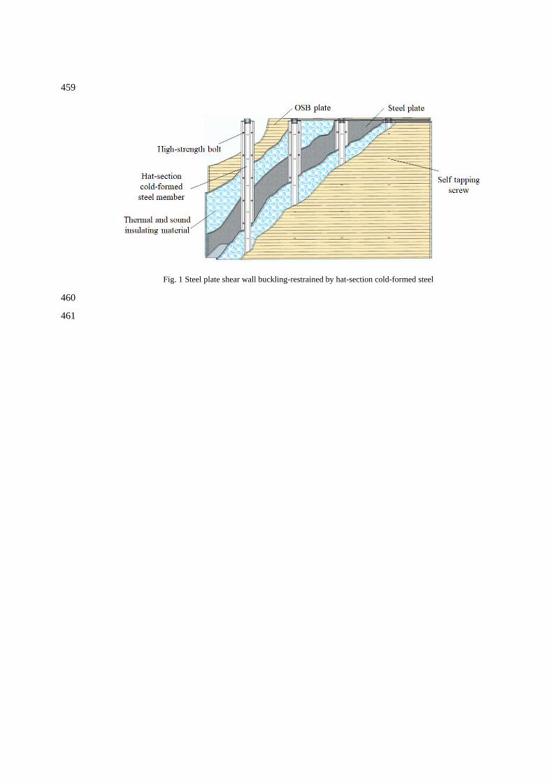
new type of SPSW buckling-restrained by hat-section cold-formed steel is proposed, as shown in Fig. 60
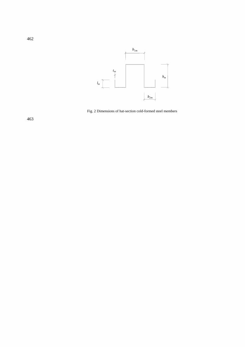
1. The hat-section cold-formed steel members (Fig. 2) are installed vertically with bolt through 61
connection on both sides of the embedded SPSW. In order to prevent the hat-section steel members 62
participating in the force deformation with the SPSW and utilize their bending resistance effectively, 63
the size of bolt holes in the SPSW is slightly larger than the diameter of connecting bolts. The 64
hat-section cold-formed steel members have the advantages of light weight, easy manufacture, 65
convenient assembling and construction. Although there are many researches on the design method 66
of SPSW [10][13], the object of these researches is the pure SPSW, which may not be applicable to 67
the SPSW buckling-restrained by hat-section cold-formed steel proposed in this paper. Therefore, it 68
is necessary to propose a design method for this new type of SPSW. Wang et al. [14] has carried out 69
experimental research on seven specimens of SPSW buckling-restrained by hat-section cold-formed 70
steel, however, the research only focuses on the preliminary qualitative exploration of the seismic 71
performance of this new type of SPSW, which cannot be used as a reference for design. Therefore, in 72
order to facilitate the practical application of this new type of SPSW and considering that the number 73
of specimens considered for the test is too small, the parametric analysis is carried out based on the 74
finite element (FE) model, and the design method of the SPSW buckling-restrained by hat-section 75
cold-formed steel is proposed based on the FE analysis results. 76
In this paper, a FE model of this new type of buckling-restrained SPSW is presented. The model 77
was validated against seven experimental results reported by Wang et al. [14]. Upon validation, a 78
total of 104 FE results were generated in the parametric analysis. Based on the theoretical analysis 79
and numerical results, a cross-bar model for calculating the stiffness and strength of the 80
buckling-restrained SPSW is developed. Afterwards, a new design method is proposed to predict the 81
stiffness, shear yielding strength and shear ultimate strength of buckling-restrained SPSW by 82
hat-section cold-formed steel. 83
2 Summary of tests 84
A total of seven SPSW buckling-restrained by hat-section cold-formed steel members have been 85
tested under low-cycle reversed shear load [14]. As illustrated in Fig. 1, the specimens were 86
comprised of one embedded SPSW and hat-section cold-formed steel members on both sides, 87
connected by M12 high-strength steel bolts. The dimensions of the embedded steel plates were all 88
1080 × 1080 × 2.66 mm (height × width × thickness); the plates were connected to four sides of the 89
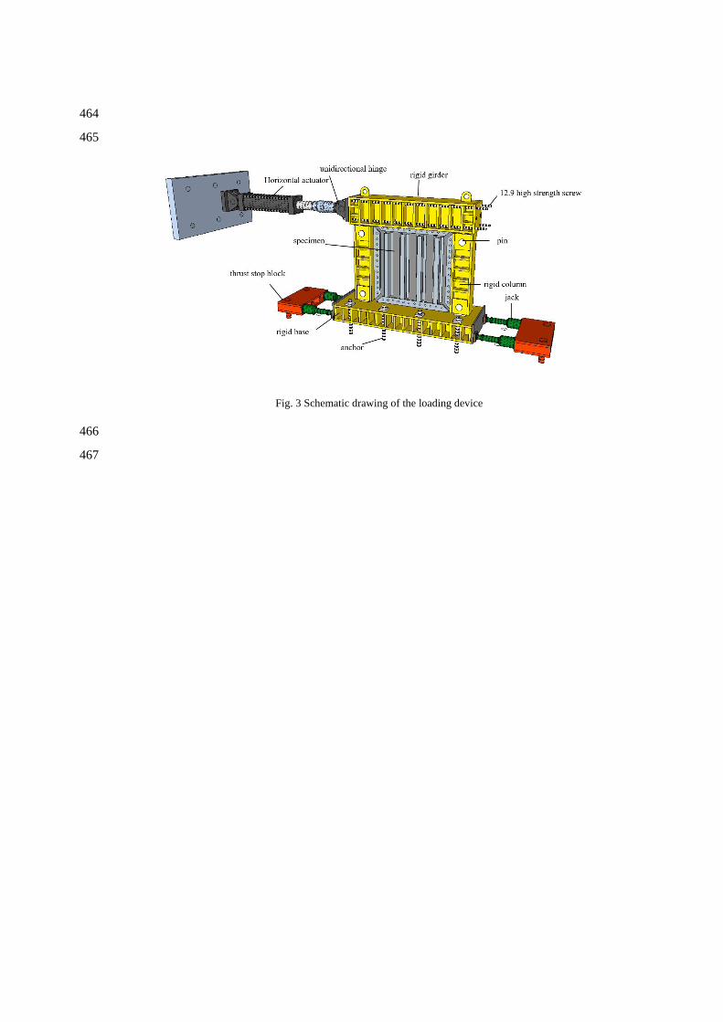
loading device (see Fig. 3) by twelve M24 high-strength steel bolts of grade 10.9. The dimensions of 90
oriented strand board (OSB) were 1000 × 1000 × 15 mm (height × width × thickness). Note that the 91
specimen NRSP was a pure SPSW as a reference comparison specimen. The detailed parameters of 92
all specimens are reported in Ref. [14] and the corresponding material properties are shown in Table 93
1. The test was carried out by load-displacement hybrid control [14, 15]. 94
3 Finite element modelling 95
The non-linear finite element (FE) analysis package ABAQUS 6.14 [16] was employed in the 96
numerical investigation herein. For the FE model, geometric nonlinearity and material nonlinearity 97
are considered, and Newton-Raphson method is used to solve the balance equation in 98
ABAQUS/Standard analysis module. An automatic stabilization method is adopted to improve the 99
convergence of the calculation. The loading of the experimental programme was reasonably 100
simplified in the modelling process to balance the efficiency and accuracy of the program calculation. 101
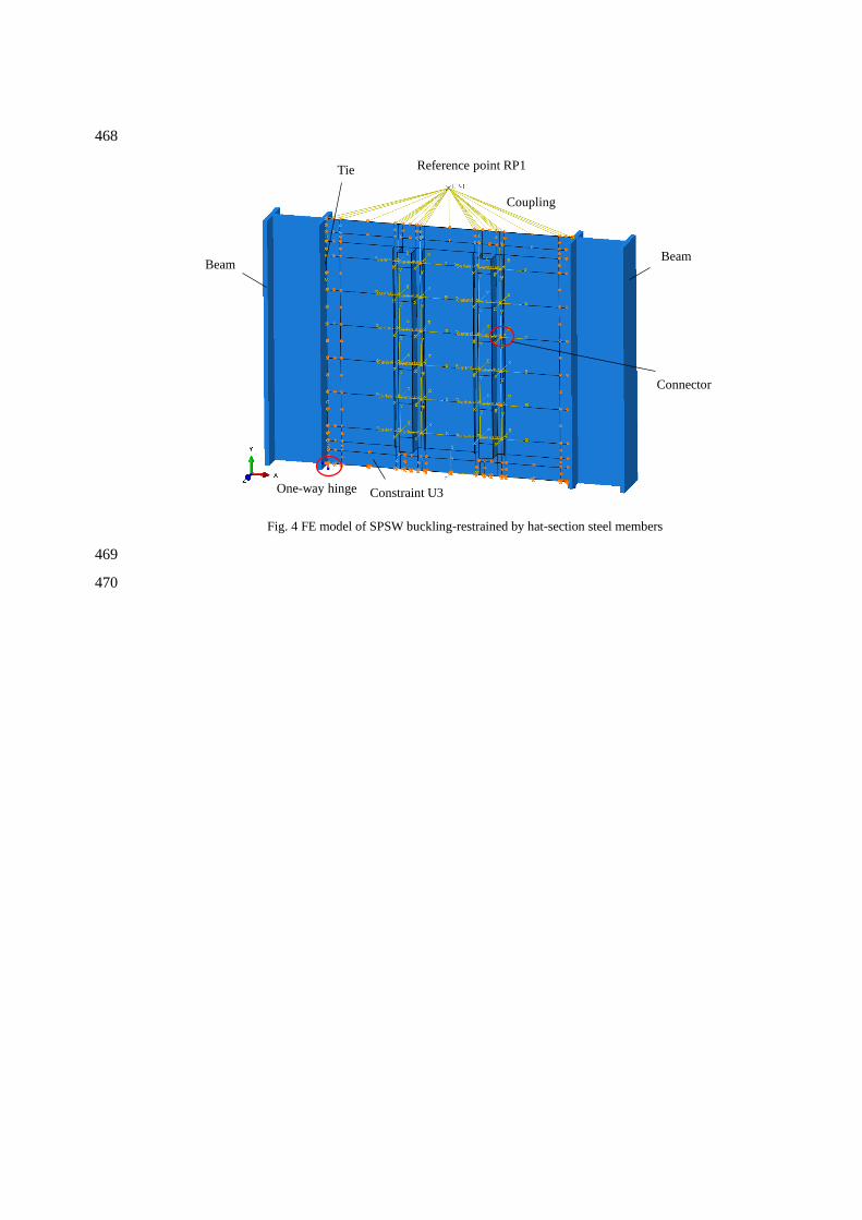
A new FE model of the SPSW buckling-restrained by hat-section cold-formed steel members was 102
developed, as illustrated in Fig. 4. 103
3.1 Material models 104
An ideal elastic-plastic constitutive model was adopted for the hat-section cold-formed steel 105
members with the yield stress σy = 345 MPa. A two-stage cyclic skeleton constitutive was adopted 106
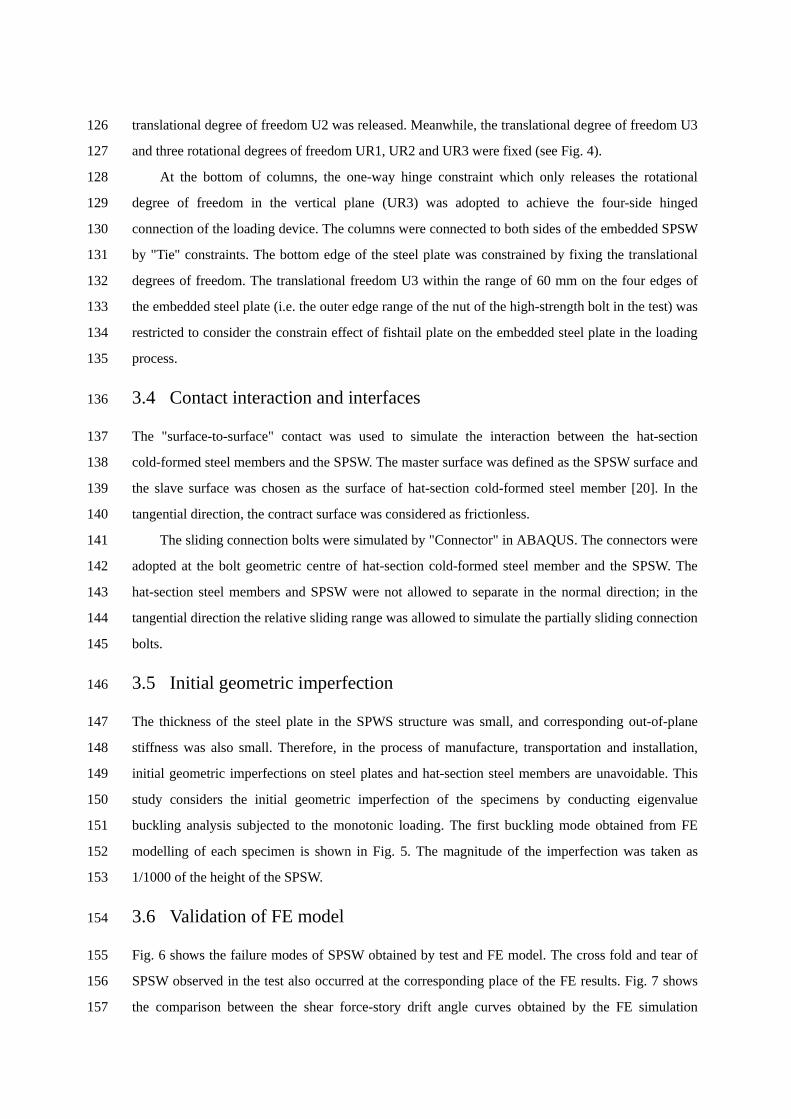
for the embedded SPSW [17] based on the results of tensile coupon, as given by Eq. (1): 107
2
, 1
= 5.796 , 1
2.486+0.608 ( 5.796) 0.00046 ( 5.796)
+ + − +
(1)
where, ( y= / ) and ( y= / ) are the regularized strain and stress respectively;εy is the 108
yield strain, σy is the yield stress. 109
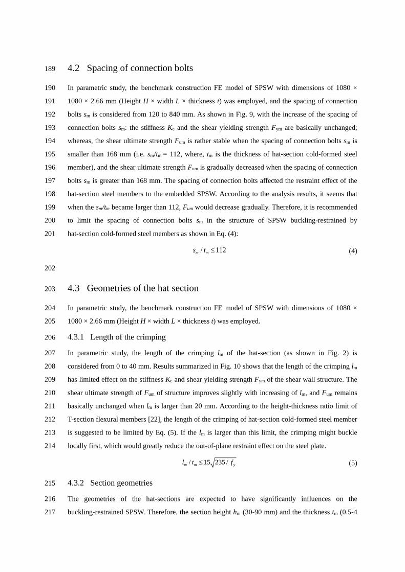
The stress and strain curves of steel materials were determined from tensile coupon tests. For 110
FE model, the true stress σtrue and the plastic strain εpl are calculated based on nominal (engineering) 111
strain εnom and nominal (engineering) stress σnom, as shown in Eqs. (2) and (3), where E is the 112
Young's modulus. 113
( )true nom nom= 1+ (2)
( ) truepl nom=ln 1+
E
− (3)
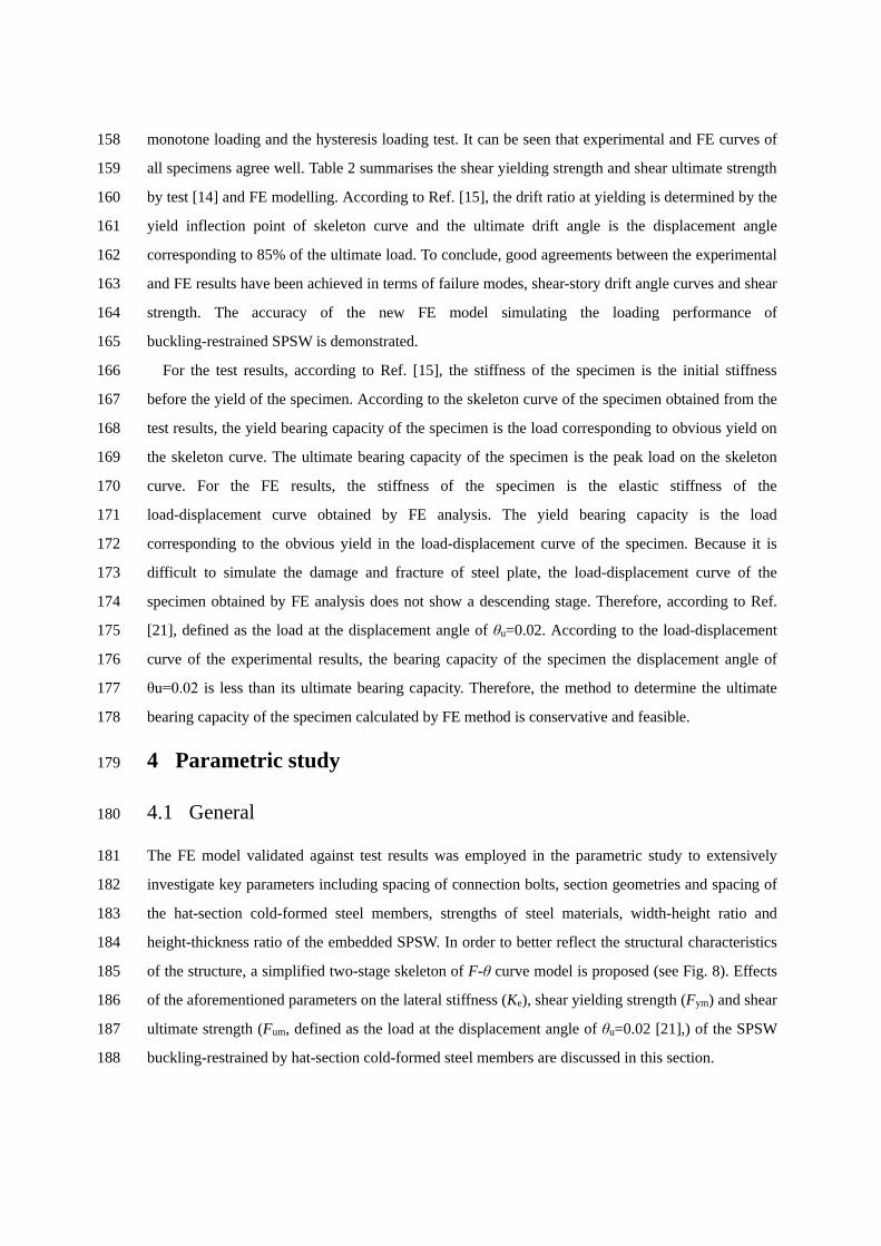
3.2 Finite element type and mesh 114
The two columns of the loading device were considered as rigid body, so beam element (B31) was 115
employed for the simulation. Shell element (S4R) was used for both embedded SPSW and 116
hat-section cold-formed steel members as widely employed for metallic structures [18, 19]. After the 117
mesh sensitivity analysis with consideration of the balance of mesh density and time cost, the final 118
mesh size was selected as 10 ×10 mm. 119
3.3 Loading and boundary conditions 120
A uniaxial simplified constitutive model of steel under cyclic load was adopted and the hysteretic 121
cyclic loading can be simulated by monotone loading [17]. A reference point RP1 (see Fig. 4) was 122
established, and the translational degrees of freedom of U1, U2 and U3 at the top of the column on 123
both sides of the loading device and the shear wall on the steel plate were coupled to reference point 124
RP1. Horizontal lateral displacement (U1) was applied to the reference point RP1 and the vertical 125
translational degree of freedom U2 was released. Meanwhile, the translational degree of freedom U3 126
and three rotational degrees of freedom UR1, UR2 and UR3 were fixed (see Fig. 4). 127
At the bottom of columns, the one-way hinge constraint which only releases the rotational 128
degree of freedom in the vertical plane (UR3) was adopted to achieve the four-side hinged 129
connection of the loading device. The columns were connected to both sides of the embedded SPSW 130
by "Tie" constraints. The bottom edge of the steel plate was constrained by fixing the translational 131
degrees of freedom. The translational freedom U3 within the range of 60 mm on the four edges of 132
the embedded steel plate (i.e. the outer edge range of the nut of the high-strength bolt in the test) was 133
restricted to consider the constrain effect of fishtail plate on the embedded steel plate in the loading 134
process. 135
3.4 Contact interaction and interfaces 136
The "surface-to-surface" contact was used to simulate the interaction between the hat-section 137
cold-formed steel members and the SPSW. The master surface was defined as the SPSW surface and 138
the slave surface was chosen as the surface of hat-section cold-formed steel member [20]. In the 139
tangential direction, the contract surface was considered as frictionless. 140
The sliding connection bolts were simulated by "Connector" in ABAQUS. The connectors were 141
adopted at the bolt geometric centre of hat-section cold-formed steel member and the SPSW. The 142
hat-section steel members and SPSW were not allowed to separate in the normal direction; in the 143
tangential direction the relative sliding range was allowed to simulate the partially sliding connection 144
bolts. 145
3.5 Initial geometric imperfection 146
The thickness of the steel plate in the SPWS structure was small, and corresponding out-of-plane 147
stiffness was also small. Therefore, in the process of manufacture, transportation and installation, 148
initial geometric imperfections on steel plates and hat-section steel members are unavoidable. This 149
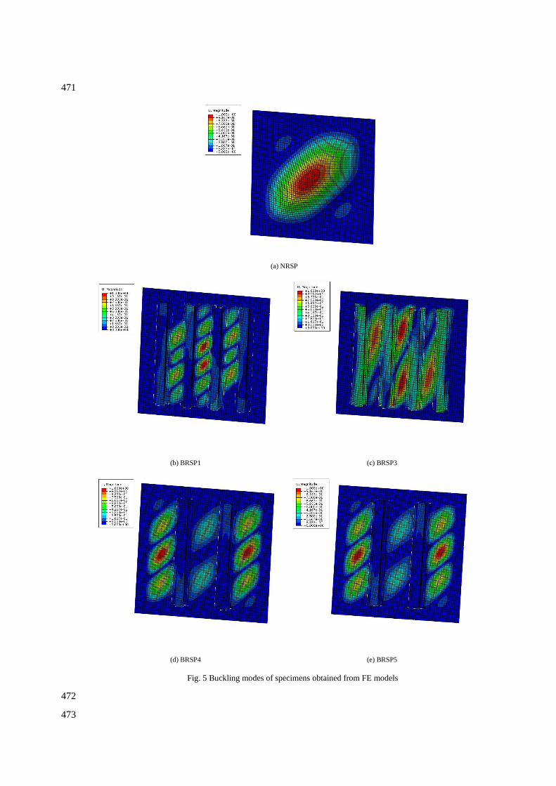
study considers the initial geometric imperfection of the specimens by conducting eigenvalue 150
buckling analysis subjected to the monotonic loading. The first buckling mode obtained from FE 151
modelling of each specimen is shown in Fig. 5. The magnitude of the imperfection was taken as 152
1/1000 of the height of the SPSW. 153
3.6 Validation of FE model 154
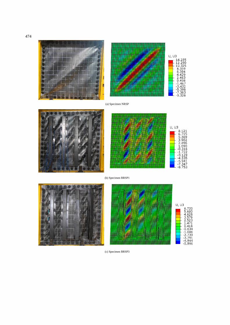
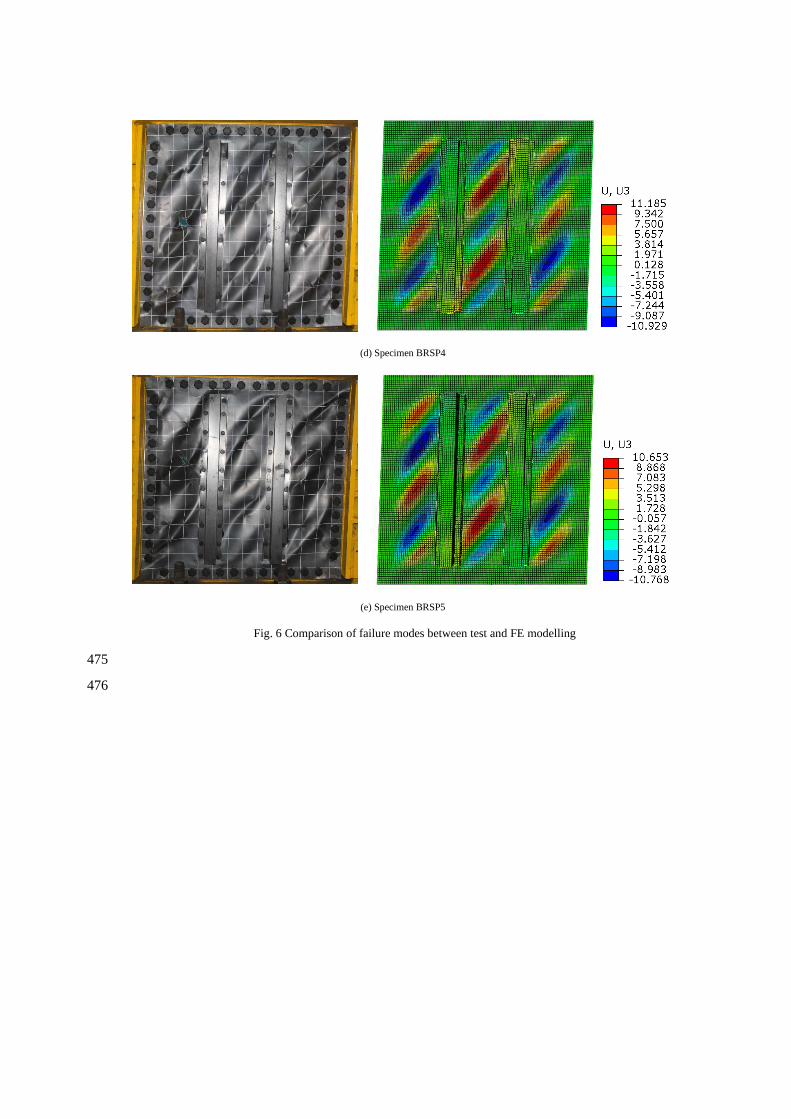
Fig. 6 shows the failure modes of SPSW obtained by test and FE model. The cross fold and tear of 155
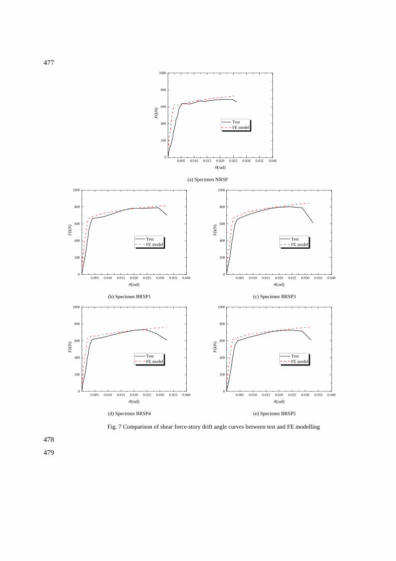
SPSW observed in the test also occurred at the corresponding place of the FE results. Fig. 7 shows 156
the comparison between the shear force-story drift angle curves obtained by the FE simulation 157
monotone loading and the hysteresis loading test. It can be seen that experimental and FE curves of 158
all specimens agree well. Table 2 summarises the shear yielding strength and shear ultimate strength 159
by test [14] and FE modelling. According to Ref. [15], the drift ratio at yielding is determined by the 160
yield inflection point of skeleton curve and the ultimate drift angle is the displacement angle 161
corresponding to 85% of the ultimate load. To conclude, good agreements between the experimental 162
and FE results have been achieved in terms of failure modes, shear-story drift angle curves and shear 163
strength. The accuracy of the new FE model simulating the loading performance of 164
buckling-restrained SPSW is demonstrated. 165
For the test results, according to Ref. [15], the stiffness of the specimen is the initial stiffness 166
before the yield of the specimen. According to the skeleton curve of the specimen obtained from the 167
test results, the yield bearing capacity of the specimen is the load corresponding to obvious yield on 168
the skeleton curve. The ultimate bearing capacity of the specimen is the peak load on the skeleton 169
curve. For the FE results, the stiffness of the specimen is the elastic stiffness of the 170
load-displacement curve obtained by FE analysis. The yield bearing capacity is the load 171
corresponding to the obvious yield in the load-displacement curve of the specimen. Because it is 172
difficult to simulate the damage and fracture of steel plate, the load-displacement curve of the 173
specimen obtained by FE analysis does not show a descending stage. Therefore, according to Ref. 174
[21], defined as the load at the displacement angle of θu=0.02. According to the load-displacement 175
curve of the experimental results, the bearing capacity of the specimen the displacement angle of 176
θu=0.02 is less than its ultimate bearing capacity. Therefore, the method to determine the ultimate 177
bearing capacity of the specimen calculated by FE method is conservative and feasible. 178
4 Parametric study 179
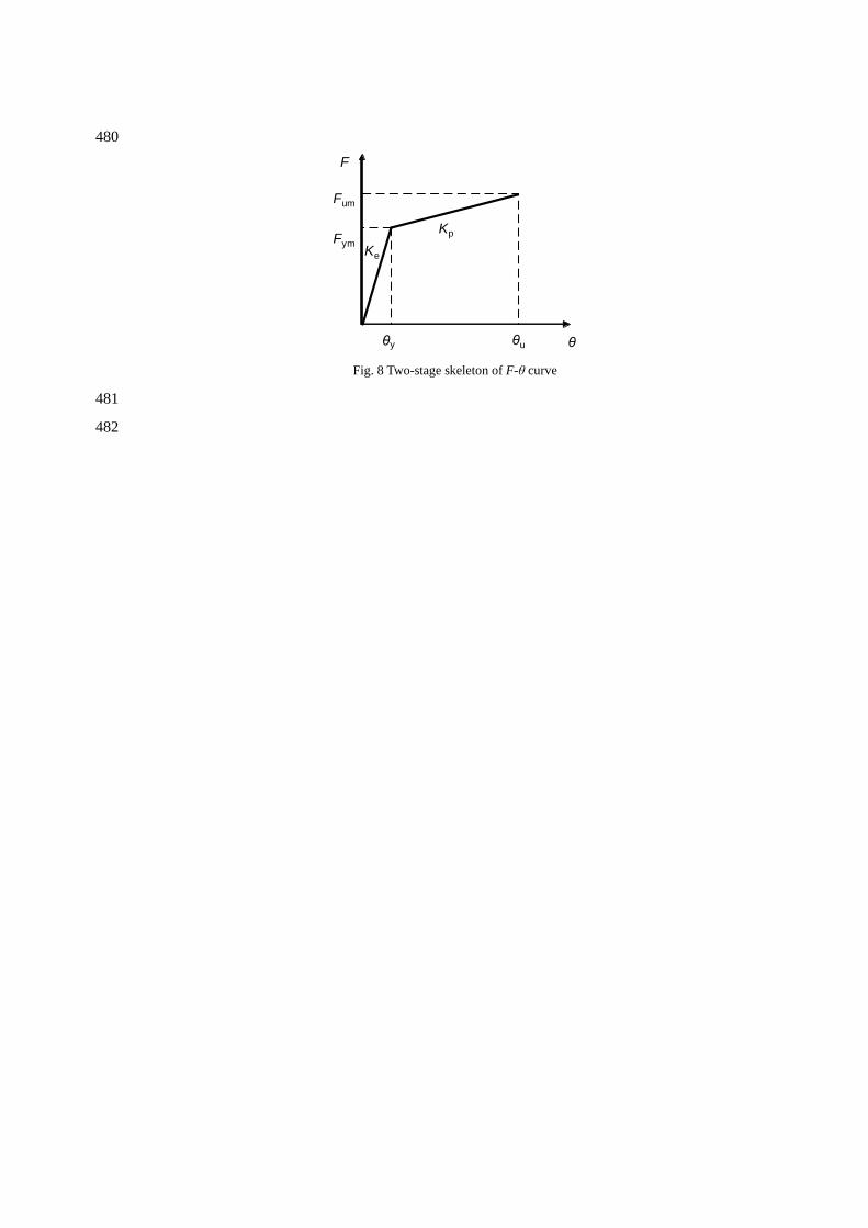
4.1 General 180
The FE model validated against test results was employed in the parametric study to extensively 181
investigate key parameters including spacing of connection bolts, section geometries and spacing of 182
the hat-section cold-formed steel members, strengths of steel materials, width-height ratio and 183
height-thickness ratio of the embedded SPSW. In order to better reflect the structural characteristics 184
of the structure, a simplified two-stage skeleton of F-θ curve model is proposed (see Fig. 8). Effects 185
of the aforementioned parameters on the lateral stiffness (Ke), shear yielding strength (Fym) and shear 186
ultimate strength (Fum, defined as the load at the displacement angle of θu=0.02 [21],) of the SPSW 187
buckling-restrained by hat-section cold-formed steel members are discussed in this section. 188
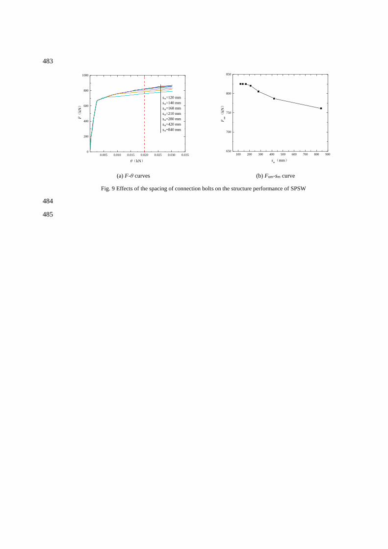
4.2 Spacing of connection bolts 189
In parametric study, the benchmark construction FE model of SPSW with dimensions of 1080 × 190
1080 × 2.66 mm (Height H × width L × thickness t) was employed, and the spacing of connection 191
bolts sm is considered from 120 to 840 mm. As shown in Fig. 9, with the increase of the spacing of 192
connection bolts sm: the stiffness Ke and the shear yielding strength Fym are basically unchanged; 193
whereas, the shear ultimate strength Fum is rather stable when the spacing of connection bolts sm is 194
smaller than 168 mm (i.e. sm/tm = 112, where, tm is the thickness of hat-section cold-formed steel 195
member), and the shear ultimate strength Fum is gradually decreased when the spacing of connection 196
bolts sm is greater than 168 mm. The spacing of connection bolts affected the restraint effect of the 197
hat-section steel members to the embedded SPSW. According to the analysis results, it seems that 198
when the sm/tm became larger than 112, Fum would decrease gradually. Therefore, it is recommended 199
to limit the spacing of connection bolts sm in the structure of SPSW buckling-restrained by 200
hat-section cold-formed steel members as shown in Eq. (4): 201
/ 112m ms t (4)
202
4.3 Geometries of the hat section 203
In parametric study, the benchmark construction FE model of SPSW with dimensions of 1080 × 204
1080 × 2.66 mm (Height H × width L × thickness t) was employed. 205
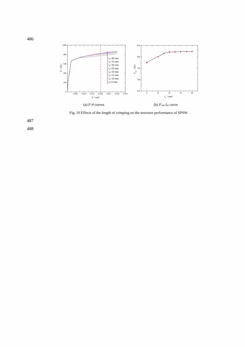
4.3.1 Length of the crimping 206
In parametric study, the length of the crimping lm of the hat-section (as shown in Fig. 2) is 207
considered from 0 to 40 mm. Results summarized in Fig. 10 shows that the length of the crimping lm 208
has limited effect on the stiffness Ke and shear yielding strength Fym of the shear wall structure. The 209
shear ultimate strength of Fum of structure improves slightly with increasing of lm, and Fum remains 210
basically unchanged when lm is larger than 20 mm. According to the height-thickness ratio limit of 211
T-section flexural members [22], the length of the crimping of hat-section cold-formed steel member 212
is suggested to be limited by Eq. (5). If the lm is larger than this limit, the crimping might buckle 213
locally first, which would greatly reduce the out-of-plane restraint effect on the steel plate. 214
/ 15 235 /m m yl t f (5)
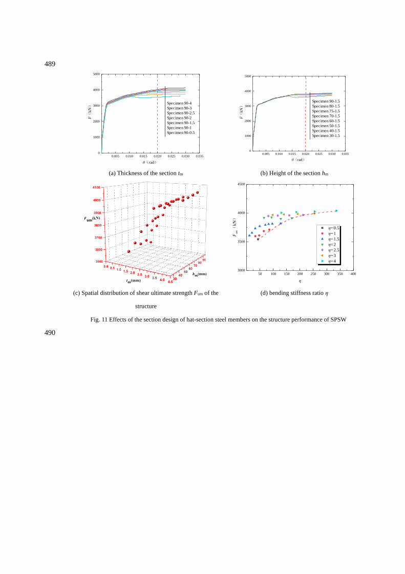
4.3.2 Section geometries 215
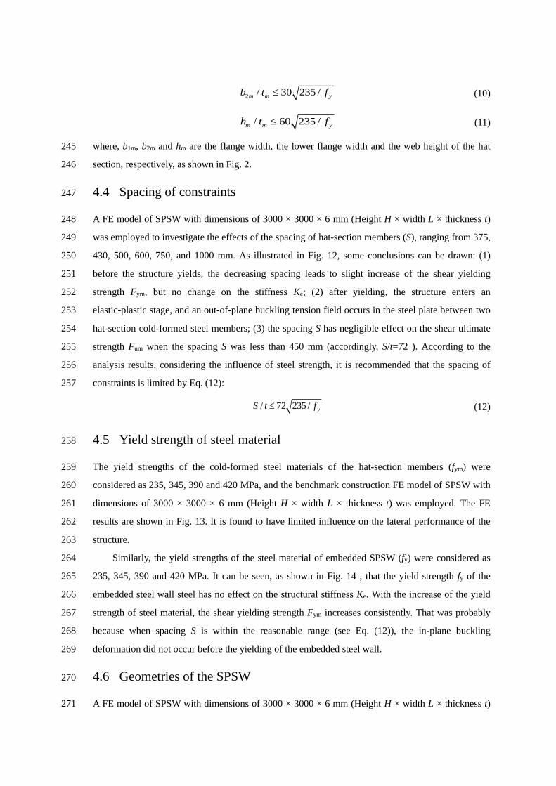
The geometries of the hat-sections are expected to have significantly influences on the 216
buckling-restrained SPSW. Therefore, the section height hm (30-90 mm) and the thickness tm (0.5-4 217
mm) are considered in the parametric study. As shown in Fig. 11(a), when the section height hm=90 218
mm, as the thickness tm of the hat-section increases: the stiffness Ke and the shear yielding strength 219
Fym are basically unchanged; the shear ultimate strength Fum increase slightly when the thickness tm 220
is smaller than 2.5 mm and keeps the same when the thickness tm is greater than 2.5 mm,. As can be 221
seen from Fig. 11(b), when the thickness is kept constant as tm=1.5 mm , the section height hm has no 222
effect on the curve stiffness Ke and shear yielding strength Fym, but positive effects on the shear 223
ultimate strength Fum. Fig. 11(c) presents the shear ultimate strength Fum with varying section height 224
hm and cold-formed steel thickness tm. 225
A bending stiffness ratio η, defined as the ratio of the out-of-plane bending flexural rigidity of 226
the hat-section members and that of the embedded SPSW on the unit width (given by Eq. (6)), is 227
introduced herein to quantify the restraining effect of the hat-section cold-formed steel member. 228
m m=
E I
Dl (6)
( )
3
2=
12 1-
EtD
(7)
where, D is the out-of-plane bending flexural rigidity per unit width of embedded SPSW (given by 229
Eq. (7), where E, t and ν are the elastic modulus, thickness and Poisson's ratio of embedded steel 230
plates, respectively); Em is the elastic modulus of the hat-section cold-formed steel member; l is the 231
width of embedded steel plate restrained by a pair of hat-section members; Im is the sum of the 232
moment of inertia of the hat-section members. 233
The relationship between the shear ultimate strength Fum and the bending stiffness ratio η is 234
shown in Fig. 11(d). When the thickness of the cold-formed steel is small, as the bending stiffness 235
ratio η of the section increases, the shear ultimate strength Fum of the structure improved slightly. For 236
the same bending stiffness ratio η, the larger of the cold-formed steel thickness tm lead to a higher 237
corresponding structural shear ultimate strength Fum. Fig. 11(d) shows that the shear ultimate 238
strength Fum reaches its upper bound when the bending stiffness ratio η is larger than 211.4 239
(corresponding to specimen 90-2.5). Based on the above analysis results, it is recommended to limit 240
the bending stiffness ratio as follows: 241
m m= 210E I
Dl (8)
Besides, in order to prevent local buckling of the hat-section members, some limits on the 242
cross-sectional dimensions are suggested as follows, with reference to the width-thickness limit 243
reported by Cui and Long [22]: 244
1 / 40 235 /m m yb t f (9)
2 / 30 235 /m m yb t f (10)
/ 60 235 /m m yh t f (11)
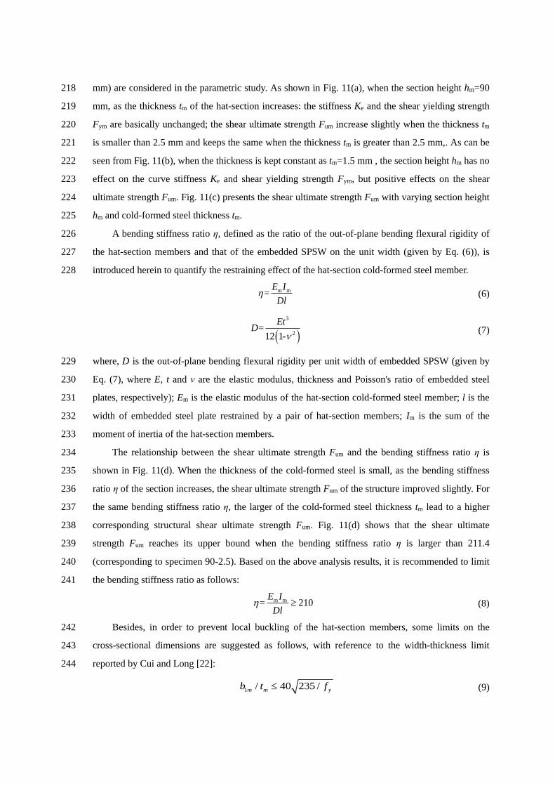
where, b1m, b2m and hm are the flange width, the lower flange width and the web height of the hat 245
section, respectively, as shown in Fig. 2. 246
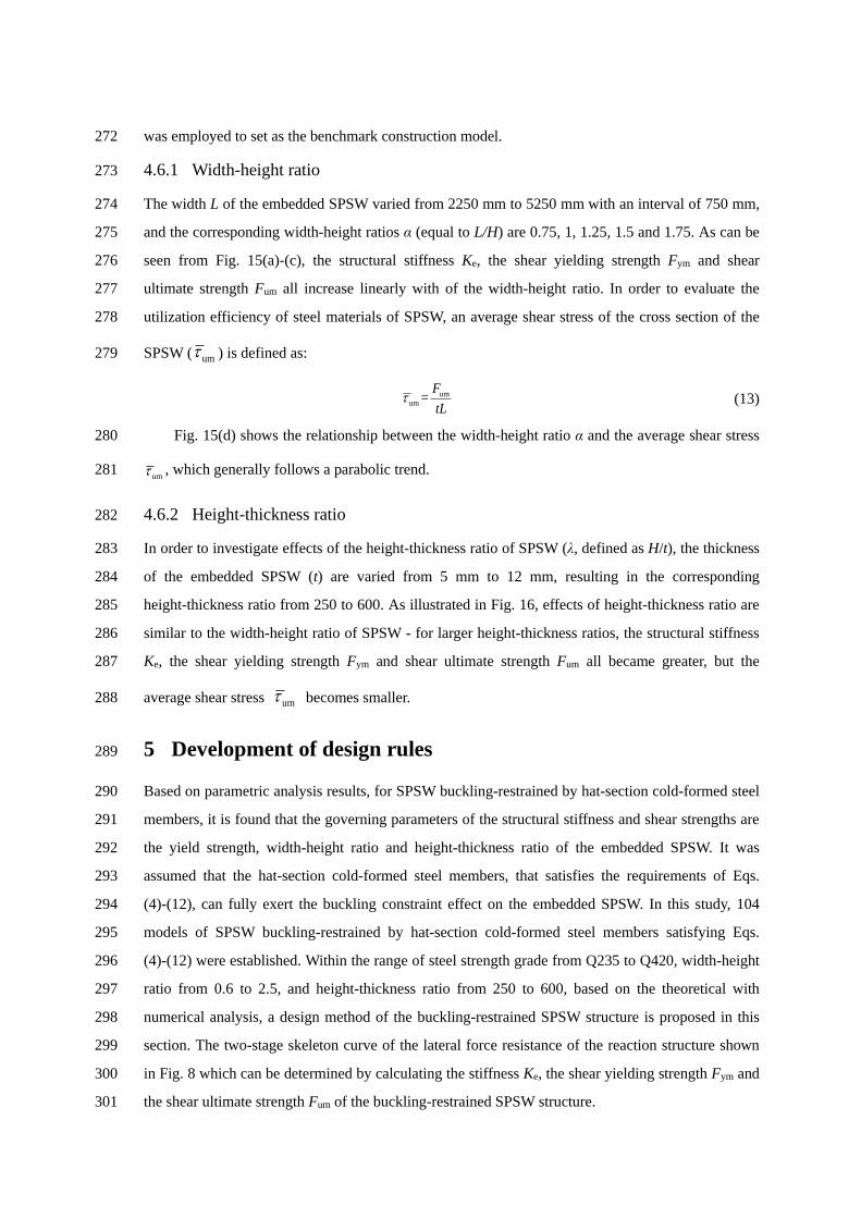
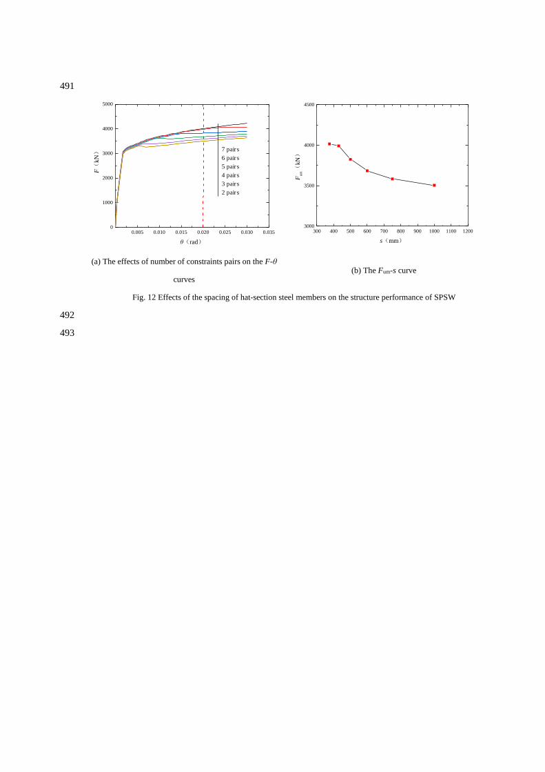
4.4 Spacing of constraints 247
A FE model of SPSW with dimensions of 3000 × 3000 × 6 mm (Height H × width L × thickness t) 248
was employed to investigate the effects of the spacing of hat-section members (S), ranging from 375, 249
430, 500, 600, 750, and 1000 mm. As illustrated in Fig. 12, some conclusions can be drawn: (1) 250
before the structure yields, the decreasing spacing leads to slight increase of the shear yielding 251
strength Fym, but no change on the stiffness Ke; (2) after yielding, the structure enters an 252
elastic-plastic stage, and an out-of-plane buckling tension field occurs in the steel plate between two 253
hat-section cold-formed steel members; (3) the spacing S has negligible effect on the shear ultimate 254
strength Fum when the spacing S was less than 450 mm (accordingly, S/t=72 ). According to the 255
analysis results, considering the influence of steel strength, it is recommended that the spacing of 256
constraints is limited by Eq. (12): 257
/ 72 235 / yS t f (12)
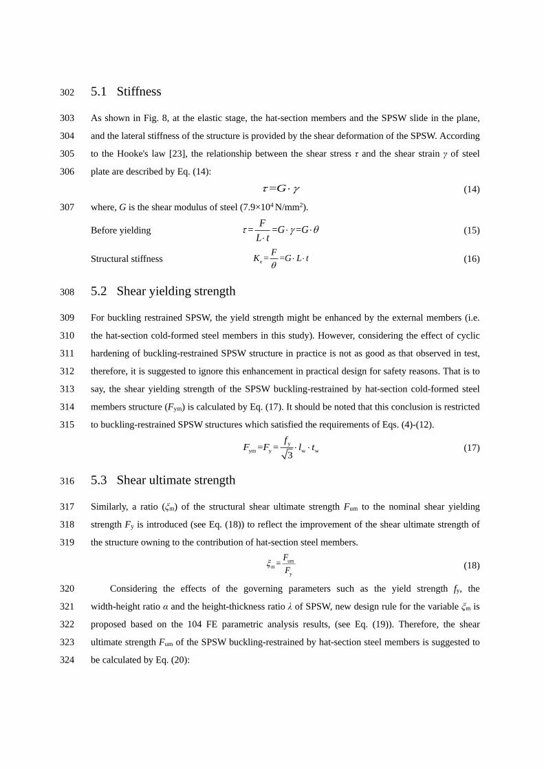
4.5 Yield strength of steel material 258
The yield strengths of the cold-formed steel materials of the hat-section members (fym) were 259
considered as 235, 345, 390 and 420 MPa, and the benchmark construction FE model of SPSW with 260
dimensions of 3000 × 3000 × 6 mm (Height H × width L × thickness t) was employed. The FE 261
results are shown in Fig. 13. It is found to have limited influence on the lateral performance of the 262
structure. 263
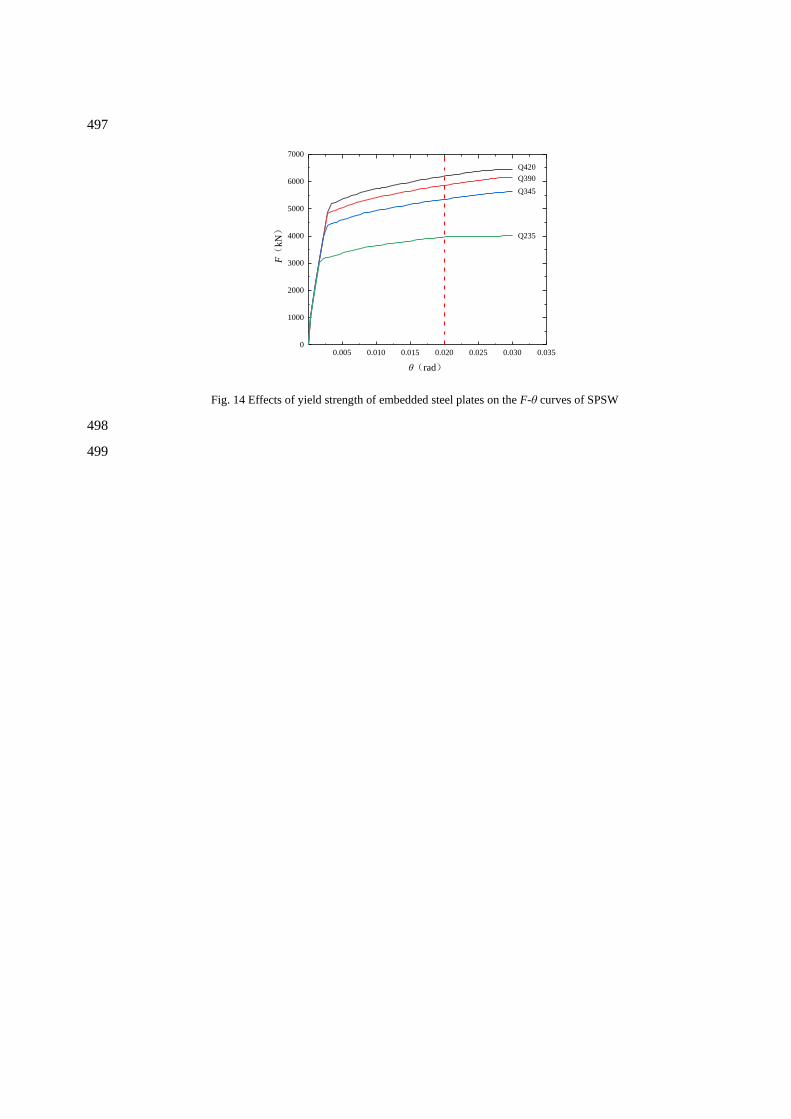
Similarly, the yield strengths of the steel material of embedded SPSW (fy) were considered as 264
235, 345, 390 and 420 MPa. It can be seen, as shown in Fig. 14 , that the yield strength fy of the 265
embedded steel wall steel has no effect on the structural stiffness Ke. With the increase of the yield 266
strength of steel material, the shear yielding strength Fym increases consistently. That was probably 267
because when spacing S is within the reasonable range (see Eq. (12)), the in-plane buckling 268
deformation did not occur before the yielding of the embedded steel wall. 269
4.6 Geometries of the SPSW 270
A FE model of SPSW with dimensions of 3000 × 3000 × 6 mm (Height H × width L × thickness t) 271
was employed to set as the benchmark construction model. 272
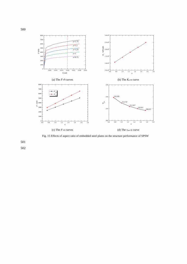
4.6.1 Width-height ratio 273
The width L of the embedded SPSW varied from 2250 mm to 5250 mm with an interval of 750 mm, 274
and the corresponding width-height ratios α (equal to L/H) are 0.75, 1, 1.25, 1.5 and 1.75. As can be 275
seen from Fig. 15(a)-(c), the structural stiffness Ke, the shear yielding strength Fym and shear 276
ultimate strength Fum all increase linearly with of the width-height ratio. In order to evaluate the 277
utilization efficiency of steel materials of SPSW, an average shear stress of the cross section of the 278
SPSW ( um ) is defined as:
279
umum =
F
tL (13)
Fig. 15(d) shows the relationship between the width-height ratio α and the average shear stress 280
um , which generally follows a parabolic trend. 281
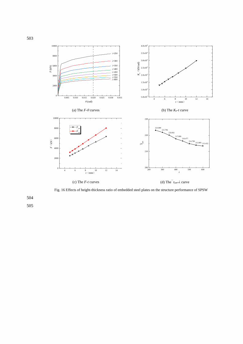
4.6.2 Height-thickness ratio 282
In order to investigate effects of the height-thickness ratio of SPSW (λ, defined as H/t), the thickness 283
of the embedded SPSW (t) are varied from 5 mm to 12 mm, resulting in the corresponding 284
height-thickness ratio from 250 to 600. As illustrated in Fig. 16, effects of height-thickness ratio are 285
similar to the width-height ratio of SPSW - for larger height-thickness ratios, the structural stiffness 286
Ke, the shear yielding strength Fym and shear ultimate strength Fum all became greater, but the 287
average shear stress um becomes smaller. 288
5 Development of design rules 289
Based on parametric analysis results, for SPSW buckling-restrained by hat-section cold-formed steel 290
members, it is found that the governing parameters of the structural stiffness and shear strengths are 291
the yield strength, width-height ratio and height-thickness ratio of the embedded SPSW. It was 292
assumed that the hat-section cold-formed steel members, that satisfies the requirements of Eqs. 293
(4)-(12), can fully exert the buckling constraint effect on the embedded SPSW. In this study, 104 294
models of SPSW buckling-restrained by hat-section cold-formed steel members satisfying Eqs. 295
(4)-(12) were established. Within the range of steel strength grade from Q235 to Q420, width-height 296
ratio from 0.6 to 2.5, and height-thickness ratio from 250 to 600, based on the theoretical with 297
numerical analysis, a design method of the buckling-restrained SPSW structure is proposed in this 298
section. The two-stage skeleton curve of the lateral force resistance of the reaction structure shown 299
in Fig. 8 which can be determined by calculating the stiffness Ke, the shear yielding strength Fym and 300
the shear ultimate strength Fum of the buckling-restrained SPSW structure. 301
5.1 Stiffness 302
As shown in Fig. 8, at the elastic stage, the hat-section members and the SPSW slide in the plane, 303
and the lateral stiffness of the structure is provided by the shear deformation of the SPSW. According 304
to the Hooke's law [23], the relationship between the shear stress τ and the shear strain γ of steel 305
plate are described by Eq. (14): 306
=G (14)
where, G is the shear modulus of steel (7.9×10⁴ N/mm2). 307
Before yielding = = =F
G GL t
(15)
Structural stiffness e = =F
K G L t
(16)
5.2 Shear yielding strength 308
For buckling restrained SPSW, the yield strength might be enhanced by the external members (i.e. 309
the hat-section cold-formed steel members in this study). However, considering the effect of cyclic 310
hardening of buckling-restrained SPSW structure in practice is not as good as that observed in test, 311
therefore, it is suggested to ignore this enhancement in practical design for safety reasons. That is to 312
say, the shear yielding strength of the SPSW buckling-restrained by hat-section cold-formed steel 313
members structure (Fym) is calculated by Eq. (17). It should be noted that this conclusion is restricted 314
to buckling-restrained SPSW structures which satisfied the requirements of Eqs. (4)-(12). 315
y
ym y w w= =3
fF F l t (17)
5.3 Shear ultimate strength 316
Similarly, a ratio (ξm) of the structural shear ultimate strength Fum to the nominal shear yielding 317
strength Fy is introduced (see Eq. (18)) to reflect the improvement of the shear ultimate strength of 318
the structure owning to the contribution of hat-section steel members. 319
um
m
y
=F
F
(18)
Considering the effects of the governing parameters such as the yield strength fy, the 320
width-height ratio α and the height-thickness ratio λ of SPSW, new design rule for the variable ξm is 321
proposed based on the 104 FE parametric analysis results, (see Eq. (19)). Therefore, the shear 322
ultimate strength Fum of the SPSW buckling-restrained by hat-section steel members is suggested to 323
be calculated by Eq. (20): 324
( ) 300m
y3.595- 5.026+0.16=0.101 0.216 0
23596 . 7
f
+
(19)
y
um m=3
fF L t (20)
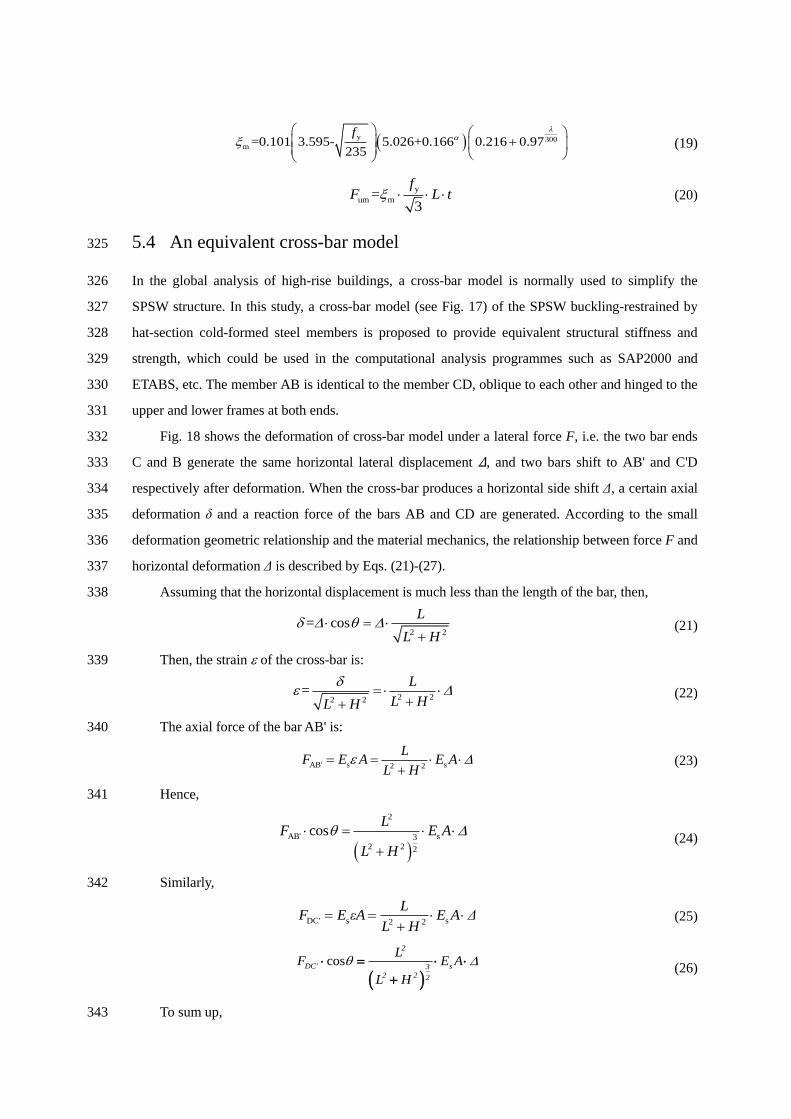
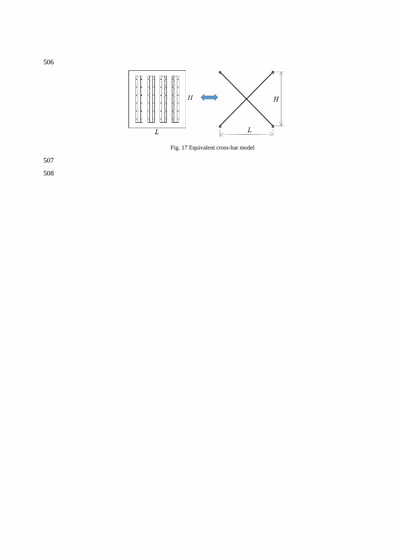
5.4 An equivalent cross-bar model 325
In the global analysis of high-rise buildings, a cross-bar model is normally used to simplify the 326
SPSW structure. In this study, a cross-bar model (see Fig. 17) of the SPSW buckling-restrained by 327
hat-section cold-formed steel members is proposed to provide equivalent structural stiffness and 328
strength, which could be used in the computational analysis programmes such as SAP2000 and 329
ETABS, etc. The member AB is identical to the member CD, oblique to each other and hinged to the 330
upper and lower frames at both ends. 331
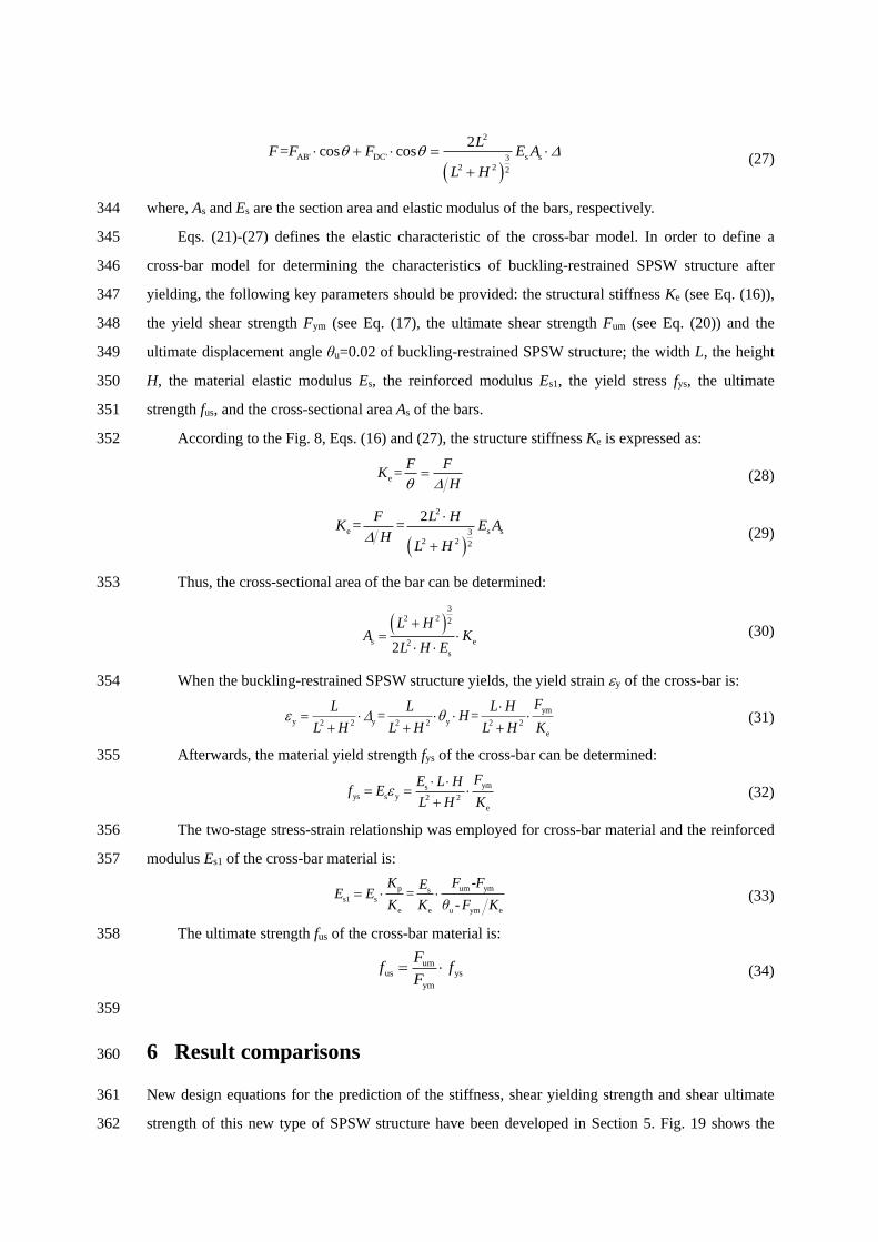
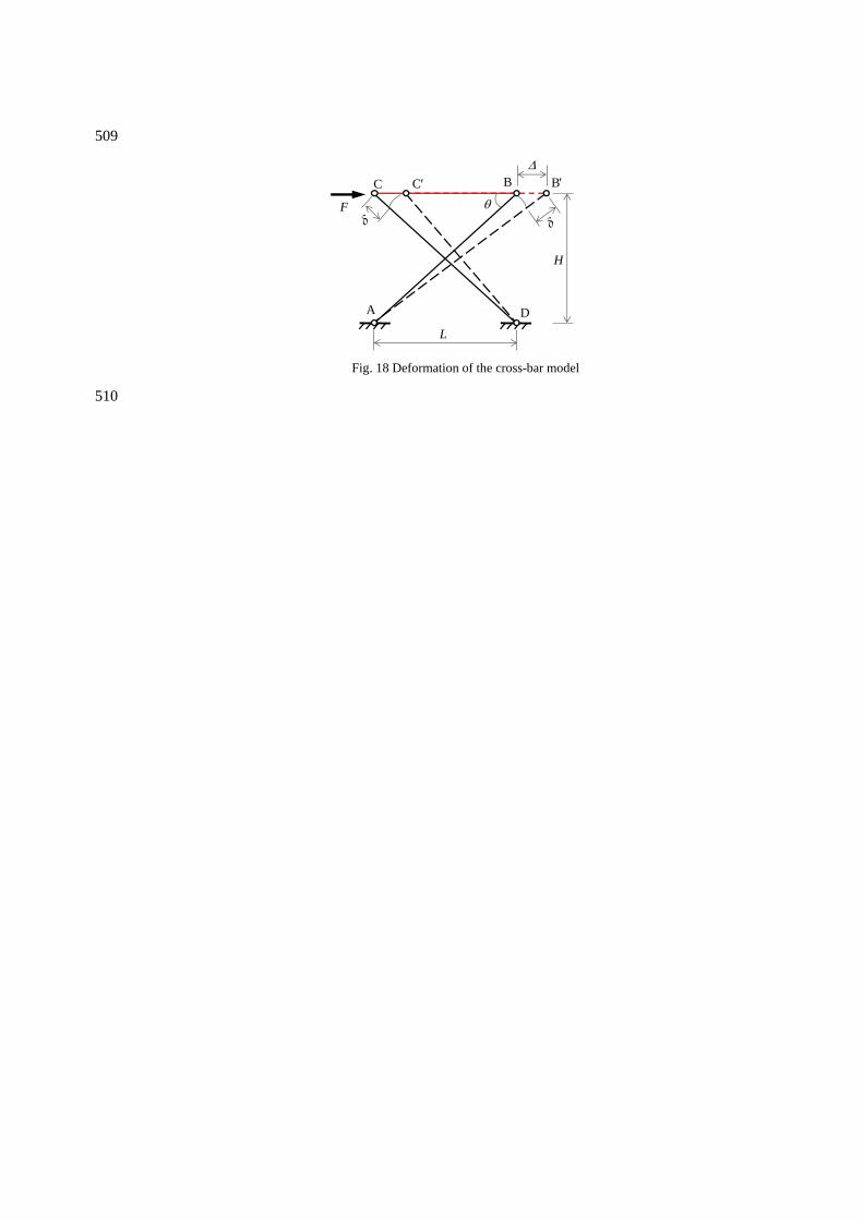
Fig. 18 shows the deformation of cross-bar model under a lateral force F, i.e. the two bar ends 332
C and B generate the same horizontal lateral displacement ∆, and two bars shift to AB' and C'D 333
respectively after deformation. When the cross-bar produces a horizontal side shift Δ, a certain axial 334
deformation δ and a reaction force of the bars AB and CD are generated. According to the small 335
deformation geometric relationship and the material mechanics, the relationship between force F and 336
horizontal deformation Δ is described by Eqs. (21)-(27). 337
Assuming that the horizontal displacement is much less than the length of the bar, then, 338
2 2= cos
L
L H =
+ (21)
Then, the strain of the cross-bar is: 339
2 22 2=
L
L HL H
=
++ (22)
The axial force of the bar AB' is: 340
AB' s s2 2
LF E A E A
L H = =
+ (23)
Hence, 341
( )
2
AB' s32 2 2
cosL
F E A
L H
=
+
(24)
Similarly, 342
DC' s s2 2
LF E εA E A Δ
L H= =
+ (25)
( )cos
2
DC' s32 2 2
LF E A
L H
=
+
(26)
To sum up, 343
( )
2
s s32 2 2
AB' DC'cos cos2
=L
E A
L H
F FF + =
+
(27)
where, As and Es are the section area and elastic modulus of the bars, respectively. 344
Eqs. (21)-(27) defines the elastic characteristic of the cross-bar model. In order to define a 345
cross-bar model for determining the characteristics of buckling-restrained SPSW structure after 346
yielding, the following key parameters should be provided: the structural stiffness Ke (see Eq. (16)), 347
the yield shear strength Fym (see Eq. (17), the ultimate shear strength Fum (see Eq. (20)) and the 348
ultimate displacement angle θu=0.02 of buckling-restrained SPSW structure; the width L, the height 349
H, the material elastic modulus Es, the reinforced modulus Es1, the yield stress fys, the ultimate 350
strength fus, and the cross-sectional area As of the bars. 351
According to the Fig. 8, Eqs. (16) and (27), the structure stiffness Ke is expressed as: 352
e =F F
KH
= (28)
( )
2
s s3e
2 2 2
= =2L H
E AH
FK
L H
+
(29)
Thus, the cross-sectional area of the bar can be determined: 353
( )3
s e
2 2 2
2
s2
L HA
L H EK
+=
(30)
When the buckling-restrained SPSW structure yields, the yield strain y of the cross-bar is: 354
ym
y y y2 2 2 2 2 2
e
= =FL L L H
HL H L H L H K
= + + +
(31)
Afterwards, the material yield strength fys of the cross-bar can be determined: 355
ymsys s y 2 2
e
FE L Hf E
L H K
= =
+ (32)
The two-stage stress-strain relationship was employed for cross-bar material and the reinforced 356
modulus Es1 of the cross-bar material is: 357
p um ymss1 s
e e u ym e
-=
-
K F FEE E
K K θ F K=
(33)
The ultimate strength fus of the cross-bar material is: 358
umus ys
ym
Ff f
F= (34)
359
6 Result comparisons 360
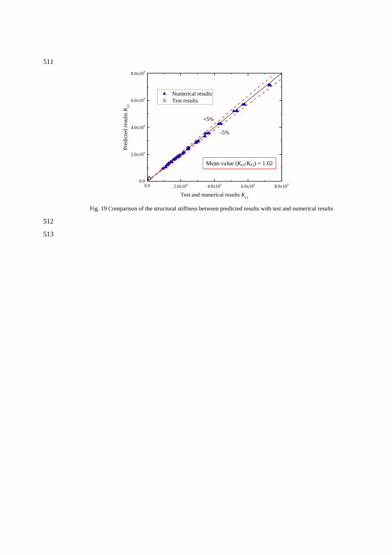
New design equations for the prediction of the stiffness, shear yielding strength and shear ultimate 361
strength of this new type of SPSW structure have been developed in Section 5. Fig. 19 shows the 362
comparison the structural stiffness Ke between numerical and predicted results. Good agreement is 363
achieved with the mean value of Ke1/Ke2 is found to be 1.02. 364
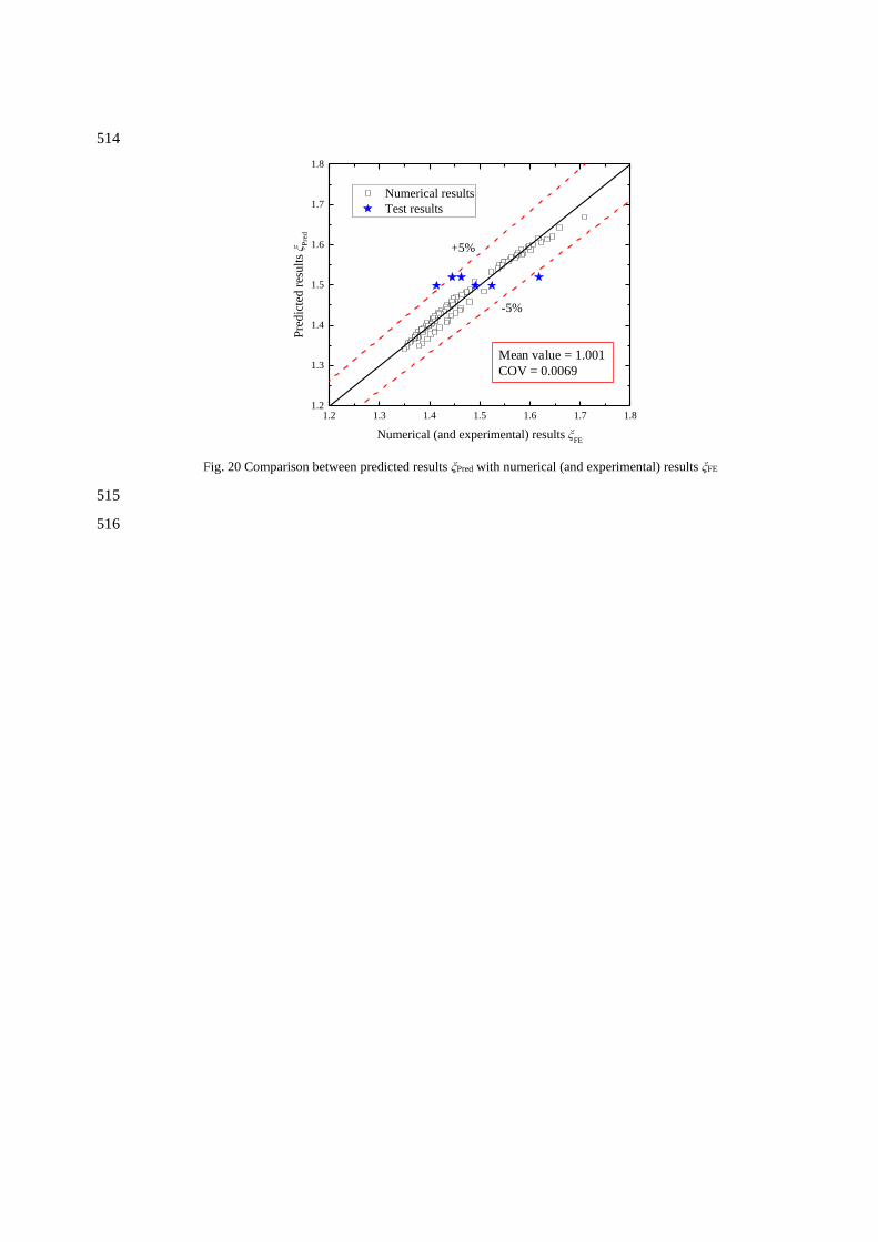
As shown in Fig. 20, for the specimens NRSP1, NRSP2, NRSP3 and NRSP6 which are 365
satisfying Eqs. (4)-(12), the predicted results of Fum are in good agreement with numerical (and 366
experimental) results of Fum with good accuracy and consistency - the mean value of the predicted 367
results to numerical (and experimental) results is 1.001 and the corresponding coefficient of variation 368
(COV) = 0.0069, variance = 0.009. 369
7 Conclusions 370
A finite element model of the steel plate shear wall (SPSW) buckling-restrained by hat-section 371
cold-formed steel members was developed and validated against the existing experimental results in 372
terms of failure modes, shear force-story drift angle curves and shear strength. In the parametric 373
study, a total of 104 numerical results were generated to consider six key parameters of this new 374
buckling-restrained SPSW structure, including spacing of connecting bolts, geometries of hat-section 375
steel, spacing of hat-section steel, steel material strength, width-height ratio of the SPSW and 376
height-thickness ratio of the SPSW. Numerical results show that: (1) effects of all the 377
aforementioned parameters on the structural stiffness of the buckling-restrained SPSW structure are 378
limited; (2) with the increase of the width-height, the shear yielding strength and shear ultimate 379
strength of SPSW increase linearly; (3) the shear yielding strength and shear ultimate strength 380
increase as the height-thickness ratio decreases; (4) with the decrease of the spacing of hat-section 381
cold-formed steel members, the shear yielding strength improves slightly, but its effect on the shear 382
ultimate strength is negligible when it is less than 450 mm. Based on numerical study and theoretical 383
analysis, requirements on the geometries of this new buckling-restrained SPSW structure are 384
suggested to ensure effective buckling-restraint on the SPSW. Within the range of steel strength 385
grade from Q235 to Q420, width-height ratio from 0.6 to 2.5, and height-thickness ratio from 250 to 386
600, new design equations for the prediction of structural stiffness, shear yielding strength and shear 387
ultimate strength of this new buckling-restrained SPSW structure are proposed. In addition, a 388
cross-bar model as a simplified equivalent model for the SPSW buckling-restrained by hat-section 389
cold-formed steel members is proposed, which could be used in the computational analysis 390
programmes such as SAP2000 and ETABS, etc. By comparing the predicted results with 391
experimental and numerical results, the proposed design method is found to be accurate and 392
consistent. 393
394
395
Acknowledgments 396
The research is supported by Scientific Research Fund of Institute of Engineering Mechanics, China 397
Earthquake Administration (Grant No. 2018D13), National Key Research and Development Program 398
of China (2017YFC0703406), the “111” Project (B18062), the Fundamental Research Fund for the 399
Central Universities (2019CDQYTM028), Project of Chongqing science and technology Bureau 400
(cstc2019jcyj-zdxm0088) and Open Project of Key Laboratory of New Technology for Construction 401
of Cities in Mountain Area (LNTCCMA-20200106). 402
403
Nomenclature 404
λ height-to-thickness ratio of steel plate
σy the yield stress of steel materials
the regularized strain of steel materials
the regularized stress of steel materials
εy the yield strain of steel materials
σtrue the true stress of steel materials
εpl the plastic strain of steel materials
εnom the nominal (engineering) strain of steel materials
σnom the nominal (engineering) stress of steel materials
E the Young's modulus of steel materials
Ke the lateral stiffness of steel plate shear wall
Fym the shear yielding strength of steel plate shear wall
Fum the shear ultimate strength of steel plate shear wall
θu the displacement angle of buckling-restrained SPSW structure
sm the spacing of connection bolts
tm the thickness of hat-section cold-formed steel member
lm the length of the crimping of the hat-section
hm the section height of the hat-section
η the ratio of the out-of-plane bending flexural rigidity of the hat-section members
and that of the embedded SPSW on the unit width
D the out-of-plane bending flexural rigidity per unit width of embedded steel plate
shear wall
t the thickness of embedded steel plates
ν the Poisson's ratio of embedded steel plates
Em the elastic modulus of the hat-section cold-formed steel member
l the width of embedded steel plate restrained by a pair of hat-section members
Im the sum of the moment of inertia of the hat-section members
b1m the flange width of the hat section
b2m the lower flange width of the hat section
hm the web height of the hat section
H the height of steel plate shear wall
L the width of steel plate shear wall
S the spacing of steel plate shear wall
fy the yield strength of steel plate shear wall
um the average shear stress of the cross section of steel plate shear wall
τ
the shear stress of steel plate
γ the shear strain of steel plate
G the shear modulus of steel
ξm the ratio of the structural shear ultimate strength Fum to the nominal shear
yielding strength Fy
α the width-height ratio of steel plate shear wall
F the lateral force cross-bar model
∆ the horizontal lateral displacement of steel plate shear wall
δ the axial deformation of the bars
As the section area of the bars
Es the elastic modulus of the bars
Es1 the reinforced modulus
fys the yield stress of the bars
fus the ultimate strength of the bars
405
References 406
[1] Dowden DM, Bruneau M. Quasi-static cyclic testing and analytical investigation of steel plate 407
shear walls with different post-tensioned beam-to-column rocking connections. Engineering 408
Structures, 2019, 187:43-56. 409
[2] Liu WY, Li GQ, Jiang J. Mechanical behavior of buckling restrained steel plate shear walls with 410
two-side connections. Engineering Structures, 2017, 138:283-292. 411
[3] Bypour M, Gholhaki M, Kioumarsi M , et al. Nonlinear analysis to investigate effect of 412
connection type on behavior of steel plate shear wall in RC frame. Engineering Structures, 2019, 413
179:611-624. 414
[4] Ozcelik Y, clayton PM. Seismic design and performance of SPSWs with beam-connected web 415
plates. Journal of Constructional Steel Research, 2018, 142: 55-67. 416
[5] Guo YL, Zhu JS QL, Zhou P, Zhu BL. A new shuttle-shaped buckling-restrained brace. 417
Theoretical study on buckling behavior and load resistance. Engineering Structures, 2017, 418
147:233-241. 419
[6] Driver RG, Kulak GL, Kennedy DJL, et al. Cyclic Test of Four-story Steel Plate Shear Wall. 420
Journal of Structural Engineering, ASCE, 1998, 124(2): 112-120. 421
[7] Lubell AS, Helmut GL, el al. Unstiffened Steel Plate Shear Wall Performance Under Cyclic 422
Loading. Journal of Structural Engineering, 2000,126(4):453-460. 423
[8] Takanashi Y, Takemoto T, Tagaki M. Experimental Study on Thin Steel Shear Walls and 424
Particular Bracing Under Alternative Horizontal Load∥Resistance and Ultimate 425
Deformability of Structures Acted on by Well-Defined Repeated Loads. Portugal:1973. 426
[9] Ge ML, Hao JP, Yu JG, Yan PZ, Xu SC. Shaking table test of buckling-restrained steel plate 427
shear walls. Journal of Constructional Steel Research, 2017, 137:254-261. 428
[10] Thorburn LJ, Kulak GL, Montgomery CJ. Analysis of steel plate shear walls. Department of 429
civil engineering, the university of Alberta, Edmonton, Alberta, 1983. 430
[11] Yu JG, Yu HS, Feng XT, Dang C, Hou TF, Shen J. Behaviour of steel plate shear walls with 431
different types of partially-encased H-section columns. Journal of Constructional Steel 432
Research, 2020, 170:106123. 433
[12] Moghimi H , Driver R G . Performance-Based Capacity Design of Steel Plate Shear Walls. I: 434
Development Principles. Journal of Structural Engineering, 2014, 140(12):04014097. 435
[13] Moghimi H , Driver R G . Performance-Based Capacity Design of Steel Plate Shear Walls. II: 436
Design Provisions. Journal of Structural Engineering, 2014, 140(12):04014098. 437
[14] Wang YH, Gu CW, Tang Q, Shi Y, Xu L, Tan JK, Luo W. Experimental Study on Cyclic Pure 438
Shear Behaviour of Hat-Section Cold-formed steel members Buckling-Restrained Steel Plate 439
Shear Walls without Effect of Frame. Engineering Structures, 2019, 201:109799. 440
[15] JGJ 101-2015 Specification of testing methods for earthquake resistant building. Beijing: China 441
Architecture & Building Press,2015 442
[16] ABAQUS, ABAQUS/Standard Version 6.14 User's Manual vols. I-III, Dassault Systèmes 443
Simulia Corp, Rhode Island, USA, 2014. 444
[17] Shi YJ, Wang M, Wang YQ. Study on constitutive model of structural steel under cyclic loading. 445
Engineering Mechanics,2012,29(09):92-98+105. 446
[18] Chen MT, Young B. Behavior of cold-formed steel elliptical hollow sections subjected to 447
bending. Journal of Constructional Steel Research, 2019, 158: 317-330. 448
[19] Chen MT, Young B. Structural behavior of cold-formed steel semi-oval hollow section beams. 449
Engineering Structures, 2019, 185: 400-411. 450
[20] Su MN, Young B, Gardner L. Deformation-based design of aluminium alloy beams. 451
Engineering Structures, 2014, 80:339-349. 452
[21] JGJ99-2015 Technical specification for steel structure of tall building. Beijing: China building 453
industry press, 2015. 454
[22] Cui J, Long LP. Basic principles of steel structure. China building industry press, 2008. 455
[23] Liu DH, Huang C. material mechanics Ӏ. Chongqing university press, 2010. 456
[24] Computers and Structures, Inc. CSI analysis manual, Berkeley, California, USA, 2018. 457
458
459
Fig. 1 Steel plate shear wall buckling-restrained by hat-section cold-formed steel
460
461
462
tm
b1m
b2m
hm
lm
Fig. 2 Dimensions of hat-section cold-formed steel members
463
464
465
Fig. 3 Schematic drawing of the loading device
466
467
468
Coupling
BeamBeam
Tie
One-way hinge Constraint U3
Reference point RP1
Connector
Fig. 4 FE model of SPSW buckling-restrained by hat-section steel members
469
470
471
(a) NRSP
(b) BRSP1 (c) BRSP3
(d) BRSP4 (e) BRSP5
Fig. 5 Buckling modes of specimens obtained from FE models
472
473
474
(a) Specimen NRSP
(b) Specimen BRSP1
(c) Specimen BRSP3
(d) Specimen BRSP4
(e) Specimen BRSP5
Fig. 6 Comparison of failure modes between test and FE modelling
475
476
477
0.005 0.010 0.015 0.020 0.025 0.030 0.035 0.0400
200
400
600
800
1000
F(k
N)
θ(rad)
Test
FE model
(a) Specimen NRSP
0.005 0.010 0.015 0.020 0.025 0.030 0.035 0.0400
200
400
600
800
1000
F(k
N)
θ(rad)
Test
FE model
0.005 0.010 0.015 0.020 0.025 0.030 0.035 0.0400
200
400
600
800
1000
F(k
N)
θ(rad)
Test
FE model
(b) Specimen BRSP1 (c) Specimen BRSP3
0.005 0.010 0.015 0.020 0.025 0.030 0.035 0.0400
200
400
600
800
1000
F(k
N)
θ(rad)
Test
FE model
0.005 0.010 0.015 0.020 0.025 0.030 0.035 0.0400
200
400
600
800
1000
F(k
N)
θ(rad)
Test
FE model
(d) Specimen BRSP4 (e) Specimen BRSP5
Fig. 7 Comparison of shear force-story drift angle curves between test and FE modelling
478
479
480
F
Ke
Fum
Fym
θθu
Kp
θy
Fig. 8 Two-stage skeleton of F-θ curve
481
482
483
0.005 0.010 0.015 0.020 0.025 0.030 0.035
200
400
600
800
1000
0
F(
kN)
θ(kN)
sm=120 mm
sm=140 mm
sm=168 mm
sm=210 mm
sm=280 mm
sm=420 mm
sm=840 mm
sm=120 mm
sm=140 mm
sm=168 mm
sm=210 mm
sm=280 mm
sm=420 mm
sm=840 mm
100 200 300 400 500 600 700 800 900650
700
750
800
850
Fum(
kN)
sm(mm)
(a) F-θ curves (b) Fum-sm curve
Fig. 9 Effects of the spacing of connection bolts on the structure performance of SPSW
484
485
486
0.005 0.010 0.015 0.020 0.025 0.030 0.0350
200
400
600
800
1000
F(
kN)
θ(rad)
lm=0 mm
lm=10 mm
lm=15 mm
lm=20 mm
lm=25 mm
lm=30 mm
lm=35 mm
lm=40 mm
lm=40 mm
lm=35 mm
lm=30 mm
lm=25 mm
lm=20 mm
lm=15 mm
lm=10 mm
lm=0 mm
0 10 20 30 40650
700
750
800
850
Fum(
kN)
lm(mm)
(a) F-θ curves (b) Fum-lm curve
Fig. 10 Effects of the length of crimping on the structure performance of SPSW
487
488
489
0.005 0.010 0.015 0.020 0.025 0.030 0.035
1000
2000
3000
4000
5000
0
F(
kN)
θ(rad)
Specimen 90-4
Specimen 90-3
Specimen 90-2.5
Specimen 90-2
Specimen 90-1.5
Specimen 90-1
Specimen 90-0.5
Specimen 90-4
Specimen 90-3
Specimen 90-2.5
Specimen 90-2
Specimen 90-1.5
Specimen 90-1
Specimen 90-0.5
0.005 0.010 0.015 0.020 0.025 0.030 0.035
1000
2000
3000
4000
5000
0
F(
kN)
θ(rad)
Specimen 90-1.5
Specimen 80-1.5
Specimen 75-1.5
Specimen 70-1.5
Specimen 60-1.5
Specimen 50-1.5
Specimen 40-1.5
Specimen 30-1.5
Specimen 90-1.5
Specimen 80-1.5
Specimen 75-1.5
Specimen 70-1.5
Specimen 60-1.5
Specimen 50-1.5
Specimen 40-1.5
Specimen 30-1.5
(a) Thickness of the section tm (b) Height of the section hm
50 100 150 200 250 300 350 400
3500
4000
4500
3000
η=0.5
η=1
η=1.5
η=2
η=2.5
η=3
η=4
Fum(
kN)
η
(c) Spatial distribution of shear ultimate strength Fum of the
structure
(d) bending stiffness ratio η
Fig. 11 Effects of the section design of hat-section steel members on the structure performance of SPSW
490
491
0.005 0.010 0.015 0.020 0.025 0.030 0.035
1000
2000
3000
4000
5000
0
F(
kN)
θ(rad)
7 pairs
6 pairs
5 pairs
4 pairs
3 pairs
2 pairs
7 pairs
6 pairs
5 pairs
4 pairs
3 pairs
2 pairs
300 400 500 600 700 800 900 1000 1100 12003000
3500
4000
4500
Fum(
kN)
s(mm)
(a) The effects of number of constraints pairs on the F-θ
curves (b) The Fum-s curve
Fig. 12 Effects of the spacing of hat-section steel members on the structure performance of SPSW
492
493

494
0.005 0.010 0.015 0.020 0.025 0.030 0.035
1000
2000
3000
4000
5000
0
F(
kN)
θ(rad)
mQ235
mQ345
mQ390
mQ420
mQ235
mQ345
mQ390
mQ420
Fig. 13 Effects of yield strength of hat-section cold-formed steel on the F-θ curves of SPSW
495
496
497
0.005 0.010 0.015 0.020 0.025 0.030 0.035
1000
2000
3000
4000
5000
6000
7000
0
F(
kN)
θ(rad)
Q420
Q390
Q345
Q235
Q420
Q390
Q345
Q235
Fig. 14 Effects of yield strength of embedded steel plates on the F-θ curves of SPSW
498
499
500
0.005 0.010 0.015 0.020 0.025 0.030 0.035
1000
2000
3000
4000
5000
6000
7000
8000
0
F (
kN
)
θ (rad)
α=1.75
α=1.5
α=1.25
α=1
α=0.75
α=1.75
α=1.5
α=1.25
α=1
α=0.75
0.6 0.8 1.0 1.2 1.4 1.6 1.8 2.05.0x10
5
1.0x10⁶
1.5x10⁶
2.0x10⁶
2.5x10⁶
3.0x10⁶
Ke(
kN
/rad
)
α
(a) The F-θ curves (b) The Ke-α curve
0.6 0.8 1.0 1.2 1.4 1.6 1.8 2.00
1000
2000
3000
4000
5000
6000
7000
8000
F(
kN)
α
Fym
Fum
0.6 0.8 1.0 1.2 1.4 1.6 1.8 2.0200
210
220
230
219.395
214.747
211.927
210.021208.637
τ um
α
(c) The F-α curves (d) The τum-α curve
Fig. 15 Effects of aspect ratio of embedded steel plates on the structure performance of SPSW
501
502
503
0.005 0.010 0.015 0.020 0.025 0.030 0.035
2000
4000
6000
8000
10000
0
F (
kN
)
θ (rad)
λ=250 λ=450
λ=300 λ=500
λ=350 λ=550
λ=400 λ=600λ=250
λ=300
λ=350
λ=450
λ=500λ=550λ=600
λ=400
4 6 8 10 12 145.0x10
5
1.0x10⁶
1.5x10⁶
2.0x10⁶
2.5x10⁶
3.0x10⁶
3.5x10⁶
4.0x10⁶
Ke(
kN
/rad
)
t(mm)
(a) The F-θ curves (b) The Ke-t curve
4 6 8 10 12 140
2000
4000
6000
8000
10000
F(
kN)
t(mm)
Fym
Fum
200 300 400 500 600200
210
220
230
223.089
221.796
220.092
217.806
216.477
214.789213.885 213.432τ u
m
λ
(c) The F-t curves (d) Theτum-λ curve
Fig. 16 Effects of height-thickness ratio of embedded steel plates on the structure performance of SPSW
504
505
506
Fig. 17 Equivalent cross-bar model
507
508
509
L
F
A
BC C B
D
H
Fig. 18 Deformation of the cross-bar model
510
511
0.0 2.0x10⁹
4.0x10⁹
6.0x10⁹
8.0x10⁹
0.0
2.0x10⁹
4.0x10⁹
6.0x10⁹
8.0x10⁹
Numerical results
Test results
-5%
Pre
dic
ted
res
ult
s K
e2
Test and numerical results Ke1
+5%
Mean value (Ke1/Ke2) = 1.02
Fig. 19 Comparison of the structural stiffness between predicted results with test and numerical results
512
513
514
1.2 1.3 1.4 1.5 1.6 1.7 1.81.2
1.3
1.4
1.5
1.6
1.7
1.8
Numerical results
Test results
-5%P
redic
ted r
esult
s ξ P
red
Numerical (and experimental) results ξFE
+5%
Mean value = 1.001
COV = 0.0069
Fig. 20 Comparison between predicted results ξPred with numerical (and experimental) results ξFE
515
516
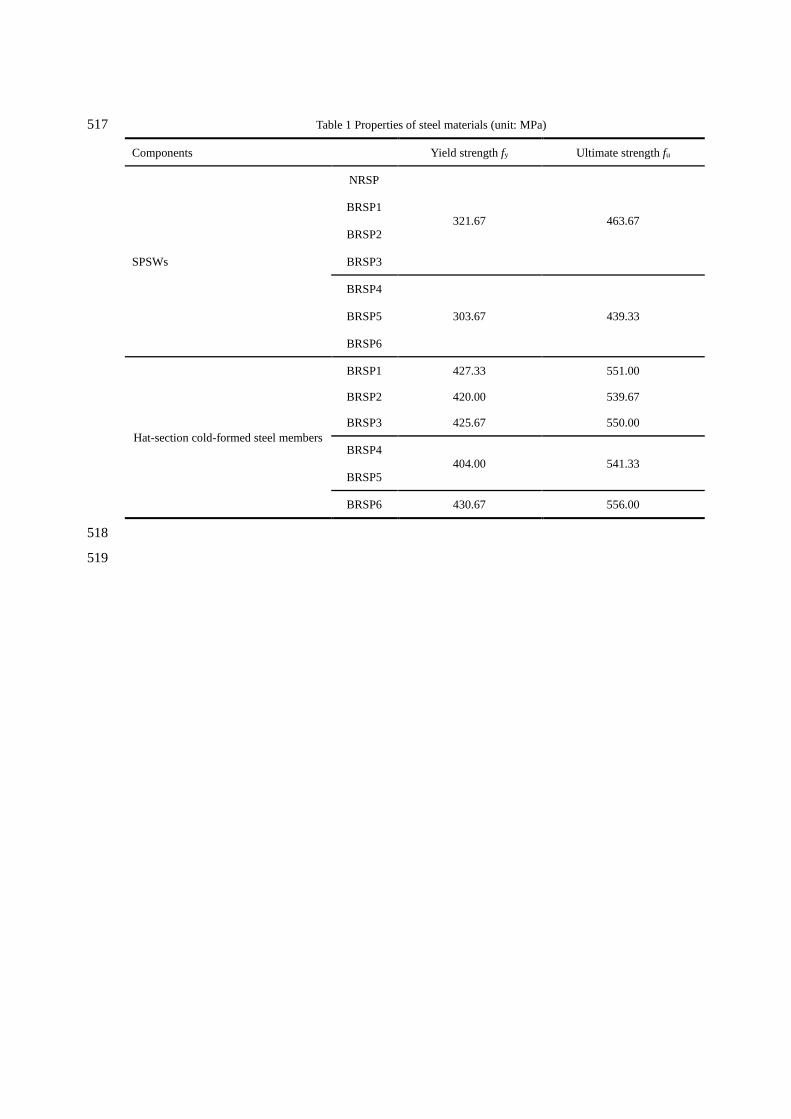
Table 1 Properties of steel materials (unit: MPa) 517
Components Yield strength fy Ultimate strength fu
SPSWs
NRSP
321.67 463.67
BRSP1
BRSP2
BRSP3
BRSP4
303.67 439.33 BRSP5
BRSP6
Hat-section cold-formed steel members
BRSP1 427.33 551.00
BRSP2 420.00 539.67
BRSP3 425.67 550.00
BRSP4
404.00 541.33 BRSP5
BRSP6 430.67 556.00
518
519
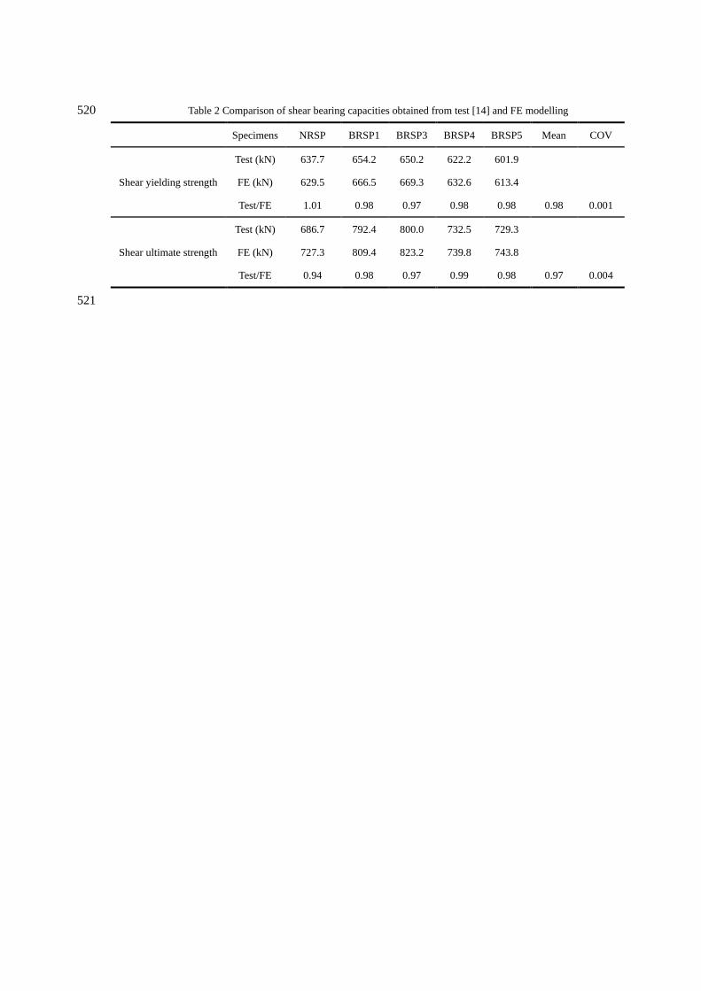
Table 2 Comparison of shear bearing capacities obtained from test [14] and FE modelling 520
Specimens NRSP BRSP1 BRSP3 BRSP4 BRSP5 Mean COV
Shear yielding strength
Test (kN) 637.7 654.2 650.2 622.2 601.9
FE (kN) 629.5 666.5 669.3 632.6 613.4
Test/FE 1.01 0.98 0.97 0.98 0.98 0.98 0.001
Shear ultimate strength
Test (kN) 686.7 792.4 800.0 732.5 729.3
FE (kN) 727.3 809.4 823.2 739.8 743.8
Test/FE 0.94 0.98 0.97 0.99 0.98 0.97 0.004
521