finite element modelling and static stress analysis … · finite element modelling and static...
TRANSCRIPT

10th International Research/Expert Conference ”Trends in the Development of Machinery and Associated Technology”
TMT 2006, Barcelona-Lloret de Mar, Spain, 11-15 September, 2006
FINITE ELEMENT MODELLING AND STATIC STRESS ANALYSIS OF SIMPLE HOOKS
M.Cuneyt FETVACI Istanbul University,
Faculty of Eng, Mech. Eng. Dept, Avcılar,
Istanbul, Turkey
Ismail GERDEMELI ITU, Faculty of Mech. Eng.
Mech.Eng. Department Gumussuyu, 34437 Istanbul, Turkey
A.Burak ERDİL ITU, Faculty of Mech. Eng.
Mech.Eng. Department Gumussuyu, 34437 Istanbul, Turkey
ABSTRACT Simple hooks in crane handling mechanisms are used safely handle and lift the loads during the lifting operation. Appropriate solution of shape and materials of hooks enables the increase of loading capacity of hoisting machines. In this study, exact solution method as an application of curved beam theory to simple hooks is presented. To investigate the static stress results, both finite element method and exact solution method are applied. An illustrative example is given to compare the stress results obtained by finite element and exact solution methods. Keywords: hook, curved beam, stress analysis 1. INTRODUCTION Generally, wire rope or chain slings attached to hooks handle cranes, which carry loads of various shapes, the load. Single and ram shorn hooks are two common designs used for this purpose. Single and ram shorn hooks may be flat-die or close die forged or else made of a series of shaped plates. After forging and machining, hooks are annealed and cleaned from scale. The inner diameter of hook should be sufficient to accommodate two strands of wire ropes or chains, which carry the load [1]. The accurate engineering analysis of material handling components in complicated forms such as hooks demands an advanced and complete mechanical computer aided engineering software. Such software packages utilize advanced mathematical algorithms to approach the engineering problems. Considerable research studies have been carried out about design and stress analysis, under static loading of crane hooks [1-3]. In this study, a single hook subject to maximum load is modelled as a curved beam with variable cross-sections along its axis. Two different methods are employed to perform the engineering analysis of a single hook. One of the methods involves the conventional engineering approache. The other method, however, takes advantage of the state of art technique of IDEAS software package facilities. In this study, finite element modelling and static stress analysis of simple hook is discussed. Both finite element method and exact solution method are investigated. 08 numbered simple hook is selected as an illustrative example and the values of stresses obtained by finite element and exact solution methods are compared. 2. GEOMETRY OF THE SINGLE HOOK Generally, cranes which carry loads of various shapes, the load is handled by chains or rope slings attached to hooks. Single and ramshorn hooks are the two most popular designs used for this purpose. Standard and ramshorn hooks may be flat-die or closed die forged or else made of a series of shaped plates. After forging and machining operations, hooks are annealed and cleaned from scale. The inner diameter of hooks should be sufficient to accommodate two strands of chains or rope which carry the load. More often than not hooks have a trapezoidal section, made wider on the inside. A trapezoidal section makes for a better utilization of the material and less complicated design. On top, the hook ends in a
797

round shank operating only in tension. The upper part of die-forged hooks is threaded for suspension from crosspieces of load carrying devices. A simple forged standard hook is shown in Figure 1. The diameter a and the overall proportions of standard and ram shorn hooks can be found in State standards. In the process of designing, the proportions of a hook are assumed tentatively on the basis of these standards; subsequently the hook is checked for strength and all its proportions are finally established.
Figure 1. Geometry of the single hook.
Calculating the hook dimensions, the hook shaft is checked for the tensile stress in the threaded portion. Hooks of small lifting capacity are provided with a normal metric vee thread. In hooks intended to carry from 5 tons and more preference is given to a trapezoidal or buttress thread. The bending moment is assumed to be positive if it causes the hook curvature to increase (its radius decreases) or negative if the curvature decreases. Since a load tends to open the hook the moment is negative [2]. 3. EXACT SOLUTION OF SIMPLE HOOK Exact stress of simple hook can be calculated considering the hook as a curved beam and its curvature is so big that it can not be assumed as a straight beam. In curved beam method, neutral axis is displaced from centroidal axis towards the center of beam curvature by effect of forces in beam symmetry plane as shown in Figure 2. Maximum bending stress is on concave surface. Cross-section of which centroidal axis is closer to concave surface should be preferred to equalize the stress and tension on outer and inner fibers [4,5].
Figure 2. Cross-section of simple hook
798

If the bending moment occurred in the cross-section of the simple hook can be written as QRM = , one can find the total stress on hook as follows
yry
kAM
AQ
−+=σ , … (1)
where Q is handling load, A = (b1+b2) h / 2 as a trapezoidal cross-section. The radius of neutral axis of this cross-section can be written
⎟⎟⎠
⎞⎜⎜⎝
⎛++
+=+=21
21 232 bb
bbhakrR . … (2)
For outer fiber of hook cross-section y = r – f is considered and from Eq.(1) the maximum stress is
f
frkA
MAQ −+=maxσ , … (3)
and for inner fiber of hook cross-section y = c – r is considered and from Eq.(1) the minimum stress is
crc
kAM
AQ −−=minσ . … (4)
4. FINITE ELEMENT ANALYSIS OF SIMPLE HOOK The finite element method is a numerical procedure that can be applied to obtain solutions to a variety of problems in engineering. Basic steps in the finite element method are defined as follows: preprocessing phase, solution phase, and post-processing phase [6]. The solid and finite element model of the simple hook is formed in I-DEAS as a computer-aided engineering software and directly analyzed applying finite elements as illustrated in Figure 3. The discretization of the simple hook is performed using quadratic solid elements.
Figure 3. Solid and finite element model of simple hook.
5. NUMERICAL EXAMPLE In order to compare the results from both exact soluion and finite element methods, an illustrative example of 08 numbered simple hook from DIN15401 is considered [7,8]. The design values of simple hook are tabulated in Table 1.
799
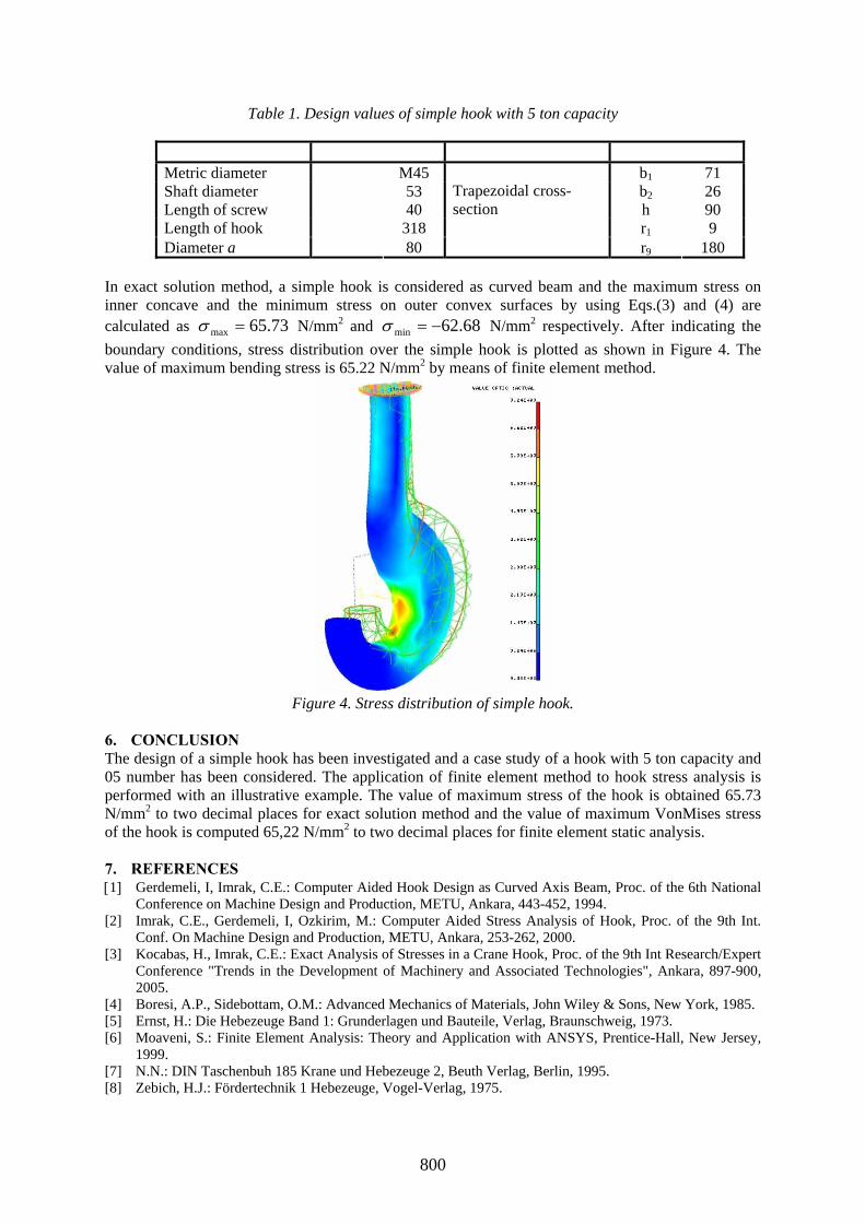
Table 1. Design values of simple hook with 5 ton capacity
Metric diameter M45 b1 71 Shaft diameter 53 b2 26 Length of screw 40 h 90 Length of hook 318 r1 9 Diameter a 80
Trapezoidal cross-section
r9 180 In exact solution method, a simple hook is considered as curved beam and the maximum stress on inner concave and the minimum stress on outer convex surfaces by using Eqs.(3) and (4) are calculated as 73.65max =σ N/mm2 and 68.62min −=σ N/mm2 respectively. After indicating the boundary conditions, stress distribution over the simple hook is plotted as shown in Figure 4. The value of maximum bending stress is 65.22 N/mm2 by means of finite element method.
Figure 4. Stress distribution of simple hook.
6. CONCLUSION The design of a simple hook has been investigated and a case study of a hook with 5 ton capacity and 05 number has been considered. The application of finite element method to hook stress analysis is performed with an illustrative example. The value of maximum stress of the hook is obtained 65.73 N/mm2 to two decimal places for exact solution method and the value of maximum VonMises stress of the hook is computed 65,22 N/mm2 to two decimal places for finite element static analysis. 7. REFERENCES [1] Gerdemeli, I, Imrak, C.E.: Computer Aided Hook Design as Curved Axis Beam, Proc. of the 6th National
Conference on Machine Design and Production, METU, Ankara, 443-452, 1994. [2] Imrak, C.E., Gerdemeli, I, Ozkirim, M.: Computer Aided Stress Analysis of Hook, Proc. of the 9th Int.
Conf. On Machine Design and Production, METU, Ankara, 253-262, 2000. [3] Kocabas, H., Imrak, C.E.: Exact Analysis of Stresses in a Crane Hook, Proc. of the 9th Int Research/Expert
Conference "Trends in the Development of Machinery and Associated Technologies", Ankara, 897-900, 2005.
[4] Boresi, A.P., Sidebottam, O.M.: Advanced Mechanics of Materials, John Wiley & Sons, New York, 1985. [5] Ernst, H.: Die Hebezeuge Band 1: Grunderlagen und Bauteile, Verlag, Braunschweig, 1973. [6] Moaveni, S.: Finite Element Analysis: Theory and Application with ANSYS, Prentice-Hall, New Jersey,
1999. [7] N.N.: DIN Taschenbuh 185 Krane und Hebezeuge 2, Beuth Verlag, Berlin, 1995. [8] Zebich, H.J.: Fördertechnik 1 Hebezeuge, Vogel-Verlag, 1975.
800