finnish maritime administration bulletin - trafi.fi · this bulletin is finnish maritime...
TRANSCRIPT
__________________________________________________________________________________________ This Bulletin is Finnish Maritime Administration Address Mail Phone Fax available from: Registrar’s Office Porkkalankatu 5 PO Box 171 +358 20 4481 +358 204484355 [email protected] FI-00180 Helsinki FI-00181 Helsinki
Finnish Maritime Administration
BULLETIN 10/10.12.2008
ICE CLASS REGULATIONS 2008 (FINNISH-SWEDISH ICE CLASS RULES) The Finnish Maritime Administration has, by a decision of 8 December 2008, issued the Ice Class Regulations (Ice Class Rules) of 2008, pursuant to section 4.1 of the Act on the Ice Classes of Ships and Icebreaker Assistance (1121/2005). The decision and the new Ice Class Regulations of 2008 enter into force on 15 December 2008. The rules in section 6 concerning the ship's propulsion machinery have been totally re-newed in the new Ice Class Rules. The Ice Class rules of 2008 shall be applied to ships on the building of which the contract has been signed on 1 January 2010 or thereafter. From 15 December 2008 the Ice Class Rules of 2008 can, however, be applied to ships on the building of which the contract has been signed on 15 December 2008 or thereafter. Enclosed are the Finnish Maritime Administration Decision on Ice Class Regulations and the application thereof and the Ice Class Regulations of 2008. Director of Maritime Safety Tuomas Routa Senior Maritime Inspector Jorma Kämäräinen For further information please contact: The Technical Division This Bulletin 13/1.10.2002 supersedes Bulletins: 12/19.12.2006 No. 2530/30/2008 ISSN 1455-9048
2
FINNISH MARITIME REGULATION Date: 8.12.2008 ADMINISTRATION No.: 2530/30/2008 Contents: Ice class regulations and the application thereof Based on: Act on the Ice Classes of Ships and Icebreaker Assistance
(1121/2005), section 4.1 Period of validity: December 15, 2008 – until further notice
_______________
FINNISH MARITIME ADMINISTRATION DECISION
ON ICE CLASS REGULATIONS AND THE APPLICATION THEREOF
Adopted in Helsinki on 8 December 2008
_______________ Pursuant to section 4.1 of the Act of 22 December 2005 on the Ice Classes of Ships and Icebreaker Assistance (1121/2005), the Finnish Maritime Administration has decided the following:
Section 1 The Ice Class Regulations of 2008 and the application thereof
The Finnish Maritime Administration has issued more detailed regulations (the Ice Class Regulations of 2008), enclosed to this decision, on the requirements concerning the struc-ture, engine output and other ice navigation properties of ships belonging to the different ice classes, on the methods for determining ice classes, and on differences between ice classes, referred to in section 4.1 of the Act on the Ice Classes of Ships and Icebreaker Assistance (1121/2005). The Ice Class Regulations (Ice Class Rules) of 2008 shall be applied to ships on the building of which the contract has been signed on 1 January 2010 or thereafter. The rules in chapter 1 (General) and 2 (Ice class draught) in the Ice Class Rules of 2008 apply to all ships irrespective of their year of build.
Section 2 Application of the 2002 Ice Class Rules
A ship the keel of which has been laid or which has been at a similar stage of construc-tion on 1 September 2003 or thereafter, but on the building of which the contract has been signed before 1 January 2010 shall comply with the FMA Ice Class Rules of 2002 (20.9.2002 No. 5/30/2002, FMA Bulletin no. 13/1.10.2002), as amended. From 15 December 2008 the Ice Class Rules of 2008 can, however, be applied to ships on the building of which the contract has been signed on 15 December 2008 or thereafter.
Section 3 Application of the 1985 Ice Class Rules
A ship the keel of which has been laid or which has been at a similar stage of construction on 1 November 1986 or thereafter, but before 1 September 2003 shall comply with the
3
requirements in the Board of Navigation Rules for Assigning Ships Separate Ice-Due Clas-ses of 1985, as amended. On the ship owner's request, however, the requirements con-cerning engine output in the FMA Ice Class Rules of 2008 can also be applied to the ship. A ship of ice class IA Super or IA the keel of which has been laid or which has been at a similar stage of construction before 1 September 2003 shall, however, comply with the requirements in section 3.2.2 of the FMA Ice Class Rules of 2008 on January 1 in the year when 20 years have elapsed since the year the ship was delivered, whichever occurs the latest.
Section 4 Application of the 1971 Ice Class Rules
The requirements of Annex I or section 10 of the Board of Navigation Rules for Assign-ing Ships Separate Ice-Due Classes of 1985 (6.4.1971 No. 1260/71/307), as amended, apply to a ship the keel of which has been laid or which has been at a similar stage of con-struction before 1 November 1986, depending on the age of the ship. On the ship owner’s request, the requirements on engine output in the Board of Navigation Rules for Assigning Ships Separate Ice-Due Classes of 1985 (2.9.1985 No. 2575/85/307) or in the FMA Ice Class Rules of 2008 may be applied to such a ship. A ship of ice class IA Super or IA the keel of which has been laid or which has been at a similar stage of construction before 1 September 2003 shall, however, comply with the requirements in section 3.2.2 of the FMA Ice Class Rules of 2008 on 1 January in the year when 20 years have elapsed since the year the ship was delivered, whichever occurs the latest
Section 5 Ice class draughts and the required minimum engine output
to be indicated in the certificate of classification The maximum and minimum ice class draught fore, amidships and aft and the required minimum engine output shall be indicated in the certificate of classification.
Section 6 Maximum draught when assistance restrictions are in force
The draught of a ship must not exceed the maximum permissible ice class draught when the ship is sailing to or from a Finnish port where assistance restrictions, requiring as a minimum ice class IC, IB or IA of ships, are in force.
Section 7 Entry into force
This decision and the enclosed Ice Class Regulations of 2008 enter into force on 15 De-cember 2008. Helsinki, 8 December 2008 Director-General Markku Mylly Director of Maritime Safety Tuomas Routa
1
ICE CLASS REGULATIONS 2008
“FINNISH-SWEDISH ICE CLASS RULES 2008”
Adopted in Helsinki on 8 December 2008 (No. 2530/30/2008)
TABLE OF CONTENTS 1 GENERAL 4
1.1 Ice classes 4
2 ICE CLASS DRAUGHT 4 2.1 Upper and lower ice waterlines 4 2.2 Maximum and minimum draught fore and aft 4
3 ENGINE OUTPUT 5 3.1 Definition of engine output 5 3.2 Required engine output for ice classes IA Super, IA, IB and IC 5
3.2.1 Definitions 5 3.2.2 New ships 6 3.2.3 Existing ships of ice class IB and IC 8 3.2.4 Existing ships of ice class IA Super or IA 8 3.2.5 Other methods of determining Ke or RCH 9
4 HULL STRUCTURAL DESIGN 9 4.1 General 9
4.1.1 Regions 10 4.2 Ice load 11
4.2.1 Height of load area 11 4.2.2 Ice pressure 11
4.3 Shell plating 13 4.3.1 Vertical extension of ice strengthening (ice belt) 13 4.3.2 Plate thickness in the ice belt 13
4.4 Frames 14 4.4.1 Vertical extension of ice strengthening 14 4.4.2 Transverse frames 15
4.4.2.1 Section modulus 15 4.4.2.2 Upper end of transverse framing 16 4.4.2.3 Lower end of transverse framing 16
4.4.3 Longitudinal frames 16 4.4.4 General on framing 17
4.4.4.1 The attachment of frames to supporting structures 17 4.4.4.2 Support of frames against tripping for ice class IA Super, for ice class IA in
the forward and midship regions and for ice classes IB and IC in the forward region of the ice-strengthened area 17
4.5 Ice stringers 17 4.5.1 Stringers within the ice belt 17
2
4.5.2 Stringers outside the ice belt 18 4.5.3 Deck strips 19
4.6 Web frames 19 4.6.1 Load 19 4.6.2 Section modulus and shear area 19 4.6.3 Direct calculations 21
4.7 Bow 21 4.7.1 Stem 21 4.7.2 Arrangements for towing 22
4.8 Stern 22 4.9 Bilge keels 23
5 RUDDER AND STEERING ARRANGEMENTS 23
6 PROPULSION MAHCINERY 24
6.1 Scope 24 6.2 Symbols 24 6.3 Design ice conditions 27 6.4 Materials 28
6.4.1 Materials exposed to sea water 28 6.4.2 Materials exposed to sea water temperature 28
6.5 Design loads 28 6.5.1 Design loads on propeller blades 28
6.5.1.1 Maximum backward blade force Fb for open propellers 28 6.5.1.2 Maximum forward blade force Ff for open propellers 29 6.5.1.3 Loaded area on the blade for open propellers 29 6.5.1.4 Maximum backward blade ice force Fb for ducted propellers 31 6.5.1.5 Maximum forward blade ice force Ff for ducted propellers 31 6.5.1.6 Loaded area on the blade for ducted propellers 31 6.5.1.7 Maximum blade spindle torque Qsmax for open and ducted propellers 32 6.5.1.8 Load distribution for blade loads 32 6.5.1.9 Number of ice loads 33
6.5.2 Axial design loads for open and ducted propellers 34 6.5.2.1 maximum ice thrust on propeller Tf and Tb for open and ducted propellers 34 6.5.2.2 Design thrust along the propulsion shaft line for open and ducted propellers 34
6.5.3 Torsional design loads 35 6.5.3.1 Design ice torque on propeller Qmax for open propellers 35 6.5.3.2 Design ice torque on propeller Qmax for ducted propellers 35 6.5.3.3 Ice torque excitation for open and ducted propellers 36 6.5.3.4 Design torque along propeller shaft line 37
6.5.4 Blade failure load 37 6.6 Design 38
6.6.1 Design principles 38 6.6.2 Propeller blade 38
6.6.2.1 Calculation of blade stresses 38 6.6.2.2 Acceptability criterion 38 6.6.2.3 Fatigue design of propeller blade 39 6.6.2.4 Acceptability criterion for fatigue 41
6.6.3 Propeller bossing and CP mechanism 42 6.6.4 Propulsion shaft line 42
6.6.4.1 Shafts and shafting components 42 6.6.5 Azimuthing main propulsors 42
3
6.6.6 Vibrations 43 6.7 Alternative design methods 43
6.7.1 Scope 43 6.7.2 Loading 43 6.7.3 Design levels 43
7 MISCELLANEOUS MACHINERY REQUIREMENTS 44
7.1 Starting arrangements 44 7.2 Sea inlet and cooling water systems 44
Annex I The validity of the powering requirement in section 3.2.2 for ice classes IA Super,
IA, IB and IC, and verification of calculated powering requirements 45 Annex II Required engine output for a ship of ice class IB or IC the keel of which has been
laid or which has been at a similar stage of construction before 1 September 2003 47 Annex III Ice class draught marking 48
4
1 GENERAL 1.1 Ice classes Under section 3 of the Act on the Ice Classes of Ships and Icebreaker Assistance (1121/2005) ships are assigned to ice classes as follows:
1. ice class IA Super; ships with such structure, engine output and other properties that they are normally capable of navigating in difficult ice conditions without the assistance of icebreakers;
2. ice class IA; ships with such structure, engine output and other properties that they are capable of navigating in difficult ice conditions, with the assistance of icebreakers when necessary;
3. ice class IB; ships with such structure, engine output and other properties that they are capable of navigating in moderate ice conditions, with the assistance of icebreakers when necessary;
4. ice class IC; ships with such structure, engine output and other properties that they are capable of navigating in light ice conditions, with the assistance of icebreakers when necessary;
5. ice class II; ships that have a steel hull and that are structurally fit for navigation in the open sea and that, despite not being strengthened for navigation in ice, are capable of navigating in very light ice conditions with their own propulsion machinery;
6. ice class III; ships that do not belong to the ice classes referred to in paragraphs 1-5. 2 ICE CLASS DRAUGHT 2.1 Upper and lower ice waterlines The upper ice waterline (UIWL) shall be the highest waterline at which the ship is intended to operate in ice. The line may be a broken line. The lower ice waterline (LIWL) shall be the lowest waterline at which the ship is intended to operate in ice. The line may be a broken line. 2.2 Maximum and minimum draught fore and aft The maximum and minimum ice class draughts at fore and aft perpendiculars shall be determined in accordance with the upper and lower ice waterlines. Restrictions on draughts when operating in ice shall be documented and kept on board readily available to the master. The maximum and minimum ice class draughts fore, amidships and aft shall be indicated in the classification certificate. For ships built on or after 1 July 2007, if the summer load line in fresh water is located at a higher level than the UIWL, the ship’s sides are to be provided with a warning triangle and with an ice class draught mark at the maximum permissible ice class draught amidships (see Annex III). Ships built before 1 July 2007 shall be provided with such a marking, if the UIWL is below the summer load line, not later than the first scheduled dry docking after 1 July 2007.
5
The draught and trim, limited by the UIWL, must not be exceeded when the ship is navigating in ice. The salinity of the sea water along the intended route shall be taken into account when loading the ship. The ship shall always be loaded down at least to the LIWL when navigating in ice. Any ballast tank, situated above the LIWL and needed to load down the ship to this water line, shall be equipped with devices to prevent the water from freezing. In determining the LIWL, regard shall be paid to the need for ensuring a reasonable degree of ice-going capability in ballast. The propeller shall be fully submerged, if possible entirely below the ice. The forward draught shall be at least: (2 + 0.00025 Δ) ho [m] but need not exceed 4ho, where
Δ is displacement of the ship [t] on the maximum ice-class draught according to 2.1.
ho is level ice thickness [m] according to 4.2.1. 3 ENGINE OUTPUT 3.1 Definition of engine output The engine output P is the maximum output the propulsion machinery can continuously deliver to the propeller(s). If the output of the machinery is restricted by technical means or by any regulations applicable to the ship, P shall be taken as the restricted output. 3.2 Required engine output for ice classes IA Super, IA, IB and IC The engine output shall not be less than that determined by the formula below and in no case less than 1000 kW for ice class IA, IB and IC, and not less than 2800 kW for IA Super.
3.2.1 Definitions The dimensions of the ship and some other parameters are defined below: L m length of the ship between the perpendiculars LBOW m length of the bow LPAR m length of the parallel midship body B m maximum breadth of the ship T m actual ice class draughts of the ship according to 3.2.2 A wf m2 area of the waterline of the bow α degree the angle of the waterline at B/4 ϕ1 degree the rake of the stem at the centerline ϕ2 degree the rake of the bow at B/4 DP m diameter of the propeller HM m thickness of the brash ice in mid channel HF m thickness of the brash ice layer displaced by the bow
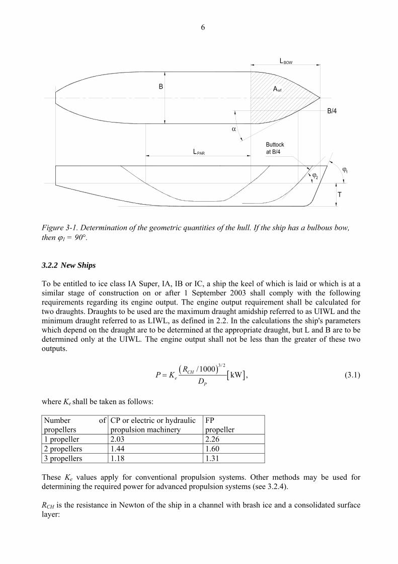
6
Figure 3-1. Determination of the geometric quantities of the hull. If the ship has a bulbous bow, then ϕ1 = 90°. 3.2.2 New Ships To be entitled to ice class IA Super, IA, IB or IC, a ship the keel of which is laid or which is at a similar stage of construction on or after 1 September 2003 shall comply with the following requirements regarding its engine output. The engine output requirement shall be calculated for two draughts. Draughts to be used are the maximum draught amidship referred to as UIWL and the minimum draught referred to as LIWL, as defined in 2.2. In the calculations the ship's parameters which depend on the draught are to be determined at the appropriate draught, but L and B are to be determined only at the UIWL. The engine output shall not be less than the greater of these two outputs.
( ) [ ]3/ 2/1000
kWCHe
P
RP K
D= , (3.1)
where Ke shall be taken as follows: Number of propellers
CP or electric or hydraulic propulsion machinery
FP propeller
1 propeller 2.03 2.26 2 propellers 1.44 1.60 3 propellers 1.18 1.31
These Ke values apply for conventional propulsion systems. Other methods may be used for determining the required power for advanced propulsion systems (see 3.2.4). RCH is the resistance in Newton of the ship in a channel with brash ice and a consolidated surface layer:
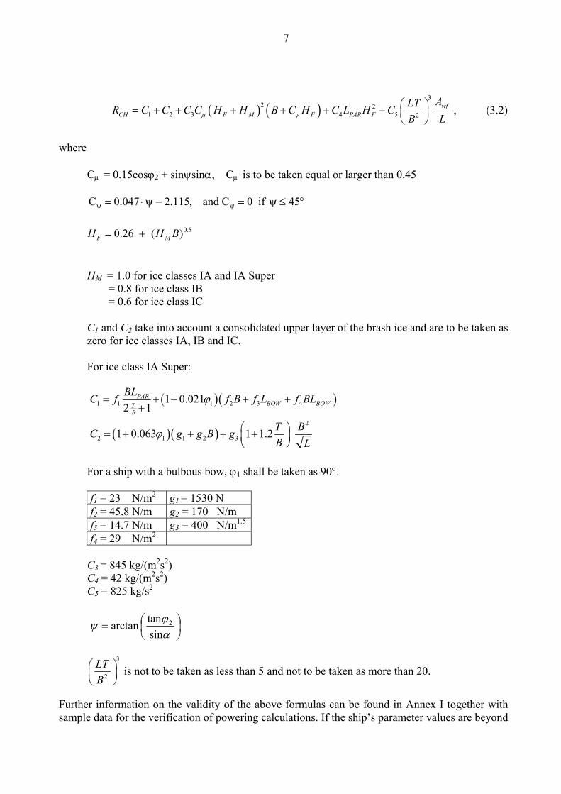
7
( ) ( )3
2 21 2 3 4 5 2
wfCH F M F PAR F
ALTR C C C C H H B C H C L H CB Lμ ψ
⎛ ⎞= + + + + + + ⎜ ⎟⎝ ⎠
, (3.2)
where
Cμ = 0.15cosϕ2 + sinψsinα, Cμ is to be taken equal or larger than 0.45
°≤ψ=−ψ⋅= 45if0Cand,115.2047.0C ψψ
0.50.26 ( )F MH H B= +
HM = 1.0 for ice classes IA and IA Super = 0.8 for ice class IB = 0.6 for ice class IC C1 and C2 take into account a consolidated upper layer of the brash ice and are to be taken as zero for ice classes IA, IB and IC. For ice class IA Super:
For a ship with a bulbous bow, ϕ1 shall be taken as 90°. f1 = 23 N/m2 g1 = 1530 N f2 = 45.8 N/m g2 = 170 N/m f3 = 14.7 N/m g3 = 400 N/m1.5
f4 = 29 N/m2 C3 = 845 kg/(m2s2) C4 = 42 kg/(m2s2) C5 = 825 kg/s2
⎟⎠⎞
⎜⎝⎛=
αϕψ
sintanarctan 2
3
2
LTB
⎛ ⎞⎜ ⎟⎝ ⎠
is not to be taken as less than 5 and not to be taken as more than 20.
Further information on the validity of the above formulas can be found in Annex I together with sample data for the verification of powering calculations. If the ship’s parameter values are beyond
( )( )
( )( )
1 1 1 2 3 4
2
2 1 1 2 3
1 0.0212 1
1 0.063 1 1.2
PARBOW BOWT
B
BLC f f B f L f BL
T BC g g B gB L
ϕ
ϕ
= + + + ++
⎛ ⎞= + + + +⎜ ⎟⎝ ⎠
8
the ranges defined in Table I-1 of Annex I, other methods for determining RCH shall be used as defined in 3.2.5.
3.2.3 Existing ships of ice class IB or IC To be entitled to retain ice class IB or IC a ship, on which the ice class regulations 1985 (2.9.1985, No. 2575/85/307 as amended) apply, shall comply with the required minimum engine output as defined in section 3.2.1 of the ice class regulations 1985. For ease of reference the provisions for ice classes IB and IC of section 3.2.1 of the ice class regulations 1985 are given in Annex II of these regulations. 3.2.4 Existing ships of ice class IA Super or IA To be entitled to retain ice class IA Super or IA a ship, the keel of which has been laid or which has been at a similar stage of construction before 1 September 2003, shall comply with the requirements in section 3.2.2 above at the following dates: - 1 January 2005 or - 1 January in the year when 20 years has elapsed since the year the ship was delivered,
whichever occurs the latest. When, for an existing ship, values for some of the hull form parameters required for the calculation method in section 3.2.2 are difficult to obtain, the following alternative formulae can be used:
( ) ( )3
2 2CH 1 2 3 4 5 2R 0.658
4F M F FLT BC C C H H B H C LH CB
⎛ ⎞= + + + + + + ⎜ ⎟⎝ ⎠
, (3.3)
where for ice class IA, C1 and C2 shall be taken as zero.
For ice class IA Super, ship without a bulb, C1 and C2 shall be calculated as follows:
( )
( )
1 1 2 3 4
2
2 1 2 3
1.842 1
3.52 1 1.2
TB
BLC f f B f L f BL
T BC g g B gB L
= + + ++
⎛ ⎞= + + +⎜ ⎟⎝ ⎠
For ice class IA Super, ship with a bulb, C1 and C2 shall be calculated as follows:
( )1 1 2 3 42.892 1T
B
BLC f f B f L f BL= + + ++
( )2
2 1 2 36.67 1 1.2 T BC g g B gB L
⎛ ⎞= + + +⎜ ⎟⎝ ⎠
,
where
9
f1 = 10.3 N/m2 g1 = 1530 N f2 = 45.8 N/m g2 = 170 N/m f3 = 2.94 N/m g3 = 400 N/m1.5
f4 = 5.8 N/m2 C3 = 460 kg/(m2s2) C4 = 18.7 kg/(m2s2) C5 = 825 kg/s2
3
2
LTB
⎛ ⎞⎜ ⎟⎝ ⎠
is not to be taken as less than 5 and not to be taken as more than 20.
3.2.5 Other methods of determining Ke or RCH For an individual ship, in lieu of the Ke or RCH values defined in 3.2.2 and 3.2.3, the use of Ke or RCH values based on more exact calculations or values based on model tests may be approved. Such an approval will be given on the understanding that it can be revoked if experience of the ship’s performance in practice motivates this. The design requirement for ice classes is a minimum speed of 5 knots in the following brash ice channels:
IA Super HM = 1.0 m and a 0.1 m thick consolidated layer of ice IA = 1.0 m IB = 0.8 m IC = 0.6 m 4 HULL STRUCTURAL DESIGN 4.1 General The method for determining the hull scantlings is based on certain assumptions concerning the nature of the ice load on the structure. These assumptions are from full scale observations made in the northern Baltic. It has thus been observed that the local ice pressure on small areas can reach rather high values. This pressure may be well in excess of the normal uniaxial crushing strength of sea ice. The explanation is that the stress field in fact is multiaxial. Further, it has been observed that the ice pressure on a frame can be higher than on the shell plating at midspacing between frames. The explanation for this is the different flexural stiffness of frames and shell plating. The load distribution is assumed to be as shown in Figure 4-1.
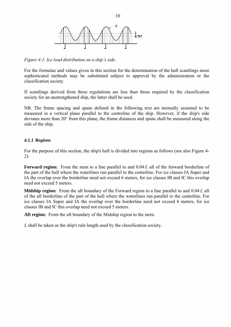
10
Figure 4-1. Ice load distribution on a ship’s side. For the formulae and values given in this section for the determination of the hull scantlings more sophisticated methods may be substituted subject to approval by the administration or the classification society. If scantlings derived from these regulations are less than those required by the classification society for an unstrengthened ship, the latter shall be used. NB. The frame spacing and spans defined in the following text are normally assumed to be measured in a vertical plane parallel to the centreline of the ship. However, if the ship's side deviates more than 20° from this plane, the frame distances and spans shall be measured along the side of the ship. 4.1.1 Regions For the purpose of this section, the ship's hull is divided into regions as follows (see also Figure 4-2): Forward region: From the stem to a line parallel to and 0.04·L aft of the forward borderline of the part of the hull where the waterlines run parallel to the centerline. For ice classes IA Super and IA the overlap over the borderline need not exceed 6 meters, for ice classes IB and IC this overlap need not exceed 5 meters.
Midship region: From the aft boundary of the Forward region to a line parallel to and 0.04·L aft of the aft borderline of the part of the hull where the waterlines run parallel to the centerline. For ice classes IA Super and IA the overlap over the borderline need not exceed 6 meters, for ice classes IB and IC this overlap need not exceed 5 meters.
Aft region: From the aft boundary of the Midship region to the stern. L shall be taken as the ship's rule length used by the classification society.
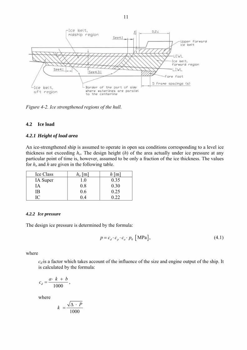
11
Figure 4-2. Ice strengthened regions of the hull. 4.2 Ice load 4.2.1 Height of load area An ice-strengthened ship is assumed to operate in open sea conditions corresponding to a level ice thickness not exceeding ho. The design height (h) of the area actually under ice pressure at any particular point of time is, however, assumed to be only a fraction of the ice thickness. The values for ho and h are given in the following table.
4.2.2 Ice pressure The design ice pressure is determined by the formula: [ ]0 MPad p ap c c c p= ⋅ ⋅ ⋅ , (4.1)
where
cd is a factor which takes account of the influence of the size and engine output of the ship. It is calculated by the formula:
1000d
a k bc ⋅ += ,
where
1000
Pk Δ ⋅=
Ice Class ho [m] h [m] IA Super IA IB IC
1.0 0.8 0.6 0.4
0.35 0.30 0.25 0.22
12
a and b are given in the following table:
Δ is the displacement of the ship at maximum ice class draught [t] (see 2.1). P is the actual continuous engine output of the ship [kW] (see 3.1). cp is a factor which takes account of the probability that the design ice pressure occurs in a certain region of the hull for the ice class in question.
The value of cp is given in the following table:
ca is a factor which takes account of the probability that the full length of the area under consideration will be under pressure at the same time. It is calculated by the formula:
0.6 minimum; 1.0 maximum;44
5-47=c aa
l ,
where la shall be taken as follows:
po is the nominal ice pressure; the value 5.6 MPa shall be used.
R e g i o n Forward Midship & Aft k ≤ 12 k > 12 k ≤ 12 k > 12
a b
30 230
6 518
8 214
2 286
R e g i o n Ice Class Forward Midship Aft
IA Super IA IB IC
1.0 1.0 1.0 1.0
1.0 0.85 0.70 0.50
0.75 0.65 0.45 0.25
Structure Type of framing la [m] Transverse Frame spacing Shell Longitudinal 2 ⋅ frame spacing Transverse Frame spacing Frames Longitudinal Span of frame
Ice stringer Span of stringer Web frame 2 ⋅ web frame spacing
13
4.3 Shell plating 4.3.1 Vertical extension of ice strengthening (ice belt) The vertical extension of the ice belt shall be as follows (see Figure 4-2):
In addition, the following areas shall be strengthened: Fore foot: For ice class IA Super, the shell plating below the ice belt from the stem to a position five main frame spaces abaft the point where the bow profile departs from the keel line shall have at least the thickness required in the ice belt in the midship region.
Upper forward ice belt: For ice classes IA Super and IA on ships with an open water service speed equal to or exceeding 18 knots, the shell plate from the upper limit of the ice belt to 2 m above it and from the stem to a position at least 0.2 L abaft the forward perpendicular, shall have at least the thickness required in the ice belt in the midship region. A similar strengthening of the bow region is advisable also for a ship with a lower service speed, when it is, e.g. on the basis of the model tests, evident that the ship will have a high bow wave. Sidescuttles shall not be situated in the ice belt. If the weather deck in any part of the ship is situated below the upper limit of the ice belt (e.g. in way of the well of a raised quarter decker), the bulwark shall be given at least the same strength as is required for the shell in the ice belt. The strength of the construction of the freeing ports shall meet the same requirements.
4.3.2 Plate thickness in the ice belt For transverse framing the thickness of the shell plating shall be determined by the formula:
[ ]1 667 mmPLc
y
f pt s tσ⋅
= + (4.2)
For longitudinal framing the thickness of the shell plating shall be determined by the formula:
[ ]2
667 mmPLc
y
pt s tf σ
= +⋅
, (4.3)
where
s is the frame spacing [m]
pPL = 0.75 p [MPa], where p is as given in 4.2.2
Ice Class Above UIWL [m]
Below LIWL [m]
IA Super 0.6 0.75 IA 0.5 0.6 IB 0.4 0.5 IC 0.4 0.5
14
1 2
4.21.3 ; maximum 1.0( / 1.8)
fh s
= −+
20.40.6 ; when h/s 1
( / )f
h s= + ≤
f2 = 1.4 - 0.4 (h/s); when 1≤ h/s < 1.8
where h is as given in 4.2.1
σy is yield stress of the material [N/mm2], for which the following values shall be used:
σy = 235 N/mm2 for normal-strength hull structural steel
σy = 315 N/mm2 or higher for high-strength hull structural steel
If steels with different yield stress are used, the actual values may be substituted for the above ones if accepted by the classification society.
tc is increment for abrasion and corrosion [mm]; normally tc shall be 2 mm; if a special surface coating, by experience shown capable to withstand the abrasion of ice, is applied and maintained, lower values may be approved.
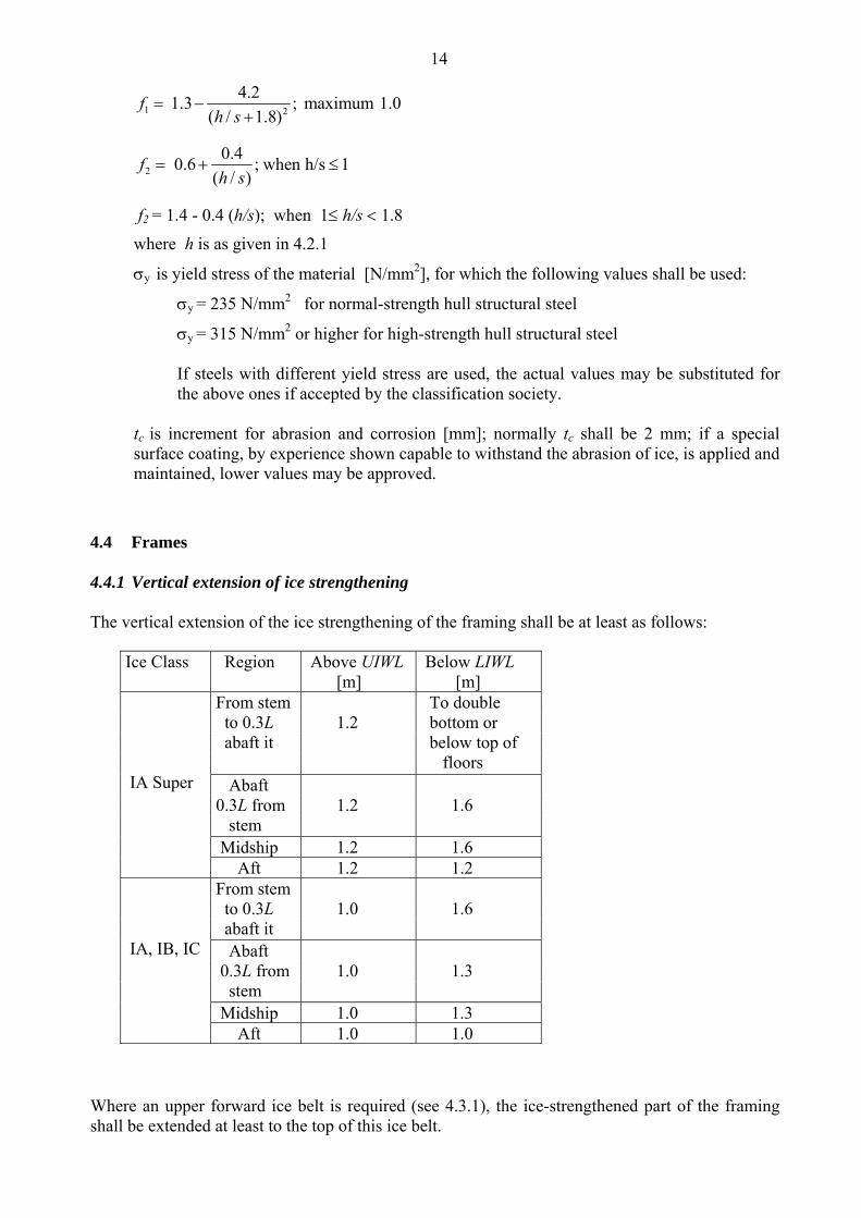
4.4 Frames 4.4.1 Vertical extension of ice strengthening The vertical extension of the ice strengthening of the framing shall be at least as follows:
Where an upper forward ice belt is required (see 4.3.1), the ice-strengthened part of the framing shall be extended at least to the top of this ice belt.
Ice Class Region Above UIWL [m]
Below LIWL [m]
From stem to 0.3L abaft it
1.2
To double bottom or below top of floors
Abaft 0.3L from stem
1.2
1.6
Midship 1.2 1.6
IA Super
Aft 1.2 1.2 From stem to 0.3L abaft it
1.0
1.6
Abaft 0.3L from stem
1.0
1.3
Midship 1.0 1.3
IA, IB, IC
Aft 1.0 1.0
15
Where the ice-strengthening would go beyond a deck or a tanktop by no more than 250 mm, it can be terminated at that deck or tanktop.
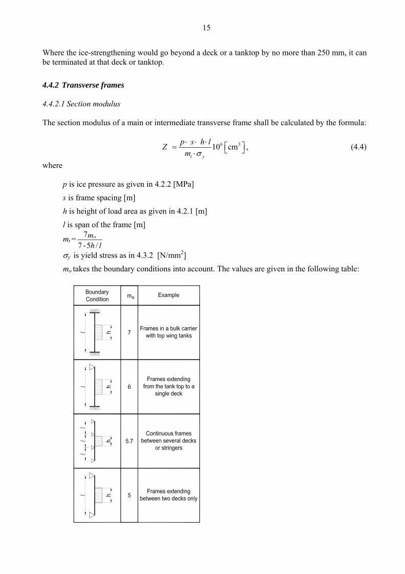
4.4.2 Transverse frames 4.4.2.1 Section modulus The section modulus of a main or intermediate transverse frame shall be calculated by the formula:
6 3 10 cmt y
p s h lZm σ⋅ ⋅ ⋅ ⎡ ⎤= ⎣ ⎦⋅
, (4.4)
where
p is ice pressure as given in 4.2.2 [MPa]
s is frame spacing [m]
h is height of load area as given in 4.2.1 [m]
l is span of the frame [m]
mt = 77 -5 /
omh l
σy is yield stress as in 4.3.2 [N/mm2]
mo takes the boundary conditions into account. The values are given in the following table:
16
The boundary conditions are those for the main and intermediate frames. Load is applied at mid span. Where less than 15% of the span, l, of the frame is situated within the ice-strengthening zone for frames as defined in 4.4.1, ordinary frame scantlings may be used.
4.4.2.2 Upper end of transverse framing The upper end of the strengthened part of a main frame and of an intermediate ice frame shall be attached to a deck of an ice stringer (section 4.5).
Where a frame terminates above a deck or a stringer which is situated at or above the upper limit of the ice belt (section 4.3.1), the part above the deck or stringer may have the scantlings required by the classification society for an unstrengthened ship and the upper end of an intermediate frame may be connected to the adjacent frames by a horizontal member having the same scantlings as the main frame. Such an intermediate frame can also be extended to the deck above, and if this is situated more than 1.8 metre above the ice belt, the intermediate frame need not be attached to that deck, except in the Forward region.
4.4.2.3 Lower end of transverse framing The lower end of the strengthened part of a main frame and of an intermediate ice frame shall be attached to a deck, tanktop or ice stringer (section 4.5).
Where an intermediate frame terminates below a deck, tanktop or ice stringer which is situated at or below the lower limit of the ice belt (section 4.3.1), the lower end may be connected to the adjacent main frames by a horizontal member of the same scantlings as the frames. 4.4.3 Longitudinal frames The section modulus of a longitudinal frame shall be calculated by the formula:
2
6 33 4 10 cmy
f f p h lZm σ
⋅ ⋅ ⋅ ⋅ ⎡ ⎤= ⎣ ⎦⋅ (4.5)
The shear area of a longitudinal frame shall be:
4 233 10 cm2 y
f p h lAσ
⋅ ⋅ ⋅ ⋅ ⎡ ⎤= ⎣ ⎦ (4.6)
This formula is valid only if the longitudinal frame is attached to supporting structure by brackets as required in 4.4.4.1. In the formulae given above:
f3 is a factor which takes account of the load distribution to adjacent frames:
f3 = (1 - 0.2 h/s)
17
f4 is a factor which takes account of the concentration of load to the point of support,
f4 = 0.6
p is ice pressure as given in 4.2.2 [MPa]
h is height of load area as given in 4.2.1 [m]
s is frame spacing [m]
The frame spacing shall not exeed 0.35 metre for ice class IA Super or IA and shall in no case exceed 0.45 metre.
l is span of frame [m]
m is a boundary condition factor; m = 13.3 for a continuous beam; where the boundary conditions deviate significantly from those of a continuous beam, e.g. in an end field, a smaller boundary factor may be required.
σy is yield stress as in 4.3.2 [N/mm2] 4.4.4 General on framing 4.4.4.1 The attachment of frames to supporting structures Within the ice-strengthened area all frames shall be effectively attached to all the supporting structures. A longitudinal frame shall be attached to all the supporting web frames and bulkheads by brackets. When a transversal frame terminates at a stringer or deck, a bracket or similar construction is to be fitted. When a frame is running through the supporting structure, both sides of the web plate of the frame are to be connected to the structure (by direct welding, collar plate or lug). When a bracket is installed, it has to have at least the same thickness as the web plate of the frame and the edge has to be appropriately stiffened against buckling. 4.4.4.2 Support of frames against tripping for ice class IA Super, for ice class IA in the forward and midship regions and for ice classes IB and IC in the forward region of the ice-strengthened area Frames which are not at a straight angle to the shell shall be supported against tripping by brackets, intercostals, stringers or similar at a distance not exceeding 1300 mm.
The frames shall be attached to the shell by double continuous weld. No scalloping is allowed (except when crossing shell plate butts).
The web thickness of the frames shall be at least one half of the thickness of the shell plating and at least 9 mm. Where there is a deck, tanktop or bulkhead in lieu of a frame, the plate thickness of this shall be as above, to a depth corresponding to the height of adjacent frames. 4.5 Ice stringers 4.5.1 Stringers within the ice belt The section modulus of a stringer situated within the ice belt (see 4.3.1) shall be calculated by the formula:
18
2
6 35
y
f p hZ 10 cmm
lσ
⋅ ⋅ ⋅ ⎡ ⎤= ⎣ ⎦⋅ (4.7)
The shear area shall be:
4 253 10 cm2 y
f p h lAσ
⋅ ⋅ ⋅ ⋅ ⎡ ⎤= ⎣ ⎦ , (4.8)
where
p is ice pressure as given in 4.2.2 [MPa]
h is height of load area as given in 4.2.1 [m]
The product p ⋅ h shall not be taken as less than 0.30.
l is span of the stringer [m]
m is a boundary condition factor as defined in 4.4.3
f5 is a factor which takes account of the distribution of load to the transverse frames; to be taken as 0.9
σy is yield stress as in 4.3.2 4.5.2 Stringers outside the ice belt The section modulus of a stringer situated outside the ice belt but supporting ice-strengthened frames shall be calculated by the formula:
( )2
6 36 1 10 cms sy
f p h lZ h lm σ⋅ ⋅ ⋅ ⎡ ⎤= − ⋅ ⎣ ⎦⋅
(4.9)
The shear area shall be:
( ) 4 263 1 10 cm2 s s
y
f p h lA h lσ
⋅ ⋅ ⋅ ⋅ ⎡ ⎤= − ⋅ ⎣ ⎦ , (4.10)
where
p is ice pressure as given in 4.2.2 [MPa]
h is height of load area as given in 4.2.1 [m]
The product p⋅ h shall not be taken as less than 0.30.
l is span of stringer [m]
m is boundary condition factor as defined in 4.4.3
ls is the distance to the adjacent ice stringer [m]
hs is the distance to the ice belt [m]
f6 is a factor which takes account of load to the transverse frames; to be taken as 0.95
19
σy is yield stress of material as in 4.3.2
4.5.3 Deck strips Narrow deck strips abreast of hatches and serving as ice stringers shall comply with the section modulus and shear area requirements in 4.5.1 and 4.5.2 respectively. In the case of very long hatches the classification society may permit the product p ⋅ h to be taken as less than 0.30 but in no case as less than 0.20. Regard shall be paid to the deflection of the ship's sides due to ice pressure in way of very long hatch openings when designing weatherdeck hatch covers and their fittings. 4.6 Web frames 4.6.1 Load The load transferred to a web frame from an ice stringer or from longitudinal framing shall be calculated by the formula: [MN]F p h S= ⋅ ⋅ , (4.11) where
p is ice pressure as given in 4.2.2 [MPa], in calculating ca however, la shall be taken as 2S.
h is height of load area as given in 4.2.1 [m]
The product p ⋅ h shall not be taken as less than 0.30
S is distance between web frames [m] In case the supported stringer is outside the ice belt, the force F shall be multiplied by (1- hs/ls), where hs and ls shall be taken as defined in 4.5.2. 4.6.2 Section modulus and shear area If a web frame is represented by the structure model shown in Figure 4-3, the section modulus and shear area shall be calculated by the formulae:
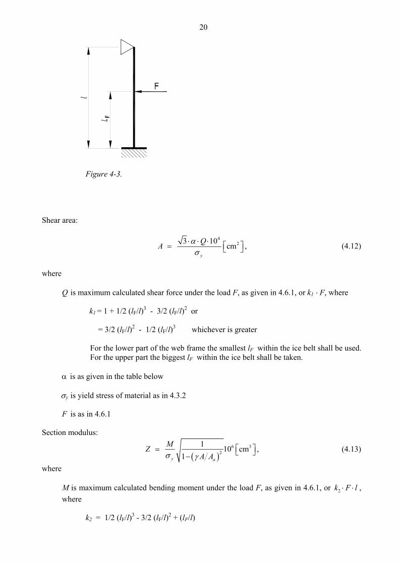
20
Figure 4-3. Shear area:
4
23 10 cmy
QA ασ
⋅ ⋅ ⋅ ⎡ ⎤= ⎣ ⎦ , (4.12)
where
Q is maximum calculated shear force under the load F, as given in 4.6.1, or k1 ⋅ F, where
k1 = 1 + 1/2 (lF/l)3 - 3/2 (lF/l)2 or
= 3/2 (lF/l)2 - 1/2 (lF/l)3 whichever is greater
For the lower part of the web frame the smallest lF within the ice belt shall be used. For the upper part the biggest lF within the ice belt shall be taken.
α is as given in the table below
σy is yield stress of material as in 4.3.2
F is as in 4.6.1
Section modulus:
( )
6 32
1 10 cm1y a
MZA Aσ γ
⎡ ⎤= ⎣ ⎦−, (4.13)
where
M is maximum calculated bending moment under the load F, as given in 4.6.1, or 2k F l⋅ ⋅ , where k2 = 1/2 (lF/l)3 - 3/2 (lF/l)2 + (lF/l)
21
γ is given in the table below A is required shear area obtained by using k1 = 1 + 1/2 (lF/l)3 - 3/2 (lF/l)2 Aa is actual cross sectional area of the web frame Factors α and γ can be obtained from the table below A f /Aw 0 0.2 0.4 0.6 0.8 1.0 1.2 1.4 1.6 1.8 2.0 α 1.5 1.23 1.16 1.11 1.09 1.07 1.06 1.05 1.05 1.04 1.04 γ 0 0.44 0.62 0.71 0.76 0.80 0.83 0.85 0.87 0.88 0.89
where
Af is cross section area of free flange Aw is cross section area of web plate
4.6.3 Direct calculations For other web frame configurations and boundary conditions than those given in 4.6.2, a direct stress calculation shall be performed. The concentrated load on the web frame is given in 4.6.1. The point of application is in each case to be chosen in relation to the arrangement of stringers and longitudinal frames so as to obtain the maximum shear and bending moments. Allowable stresses are as follows: Shear stress: y 3τ σ= (4.14) Bending stress: b y= σ σ (4.15) Equivalent stress: 2 2
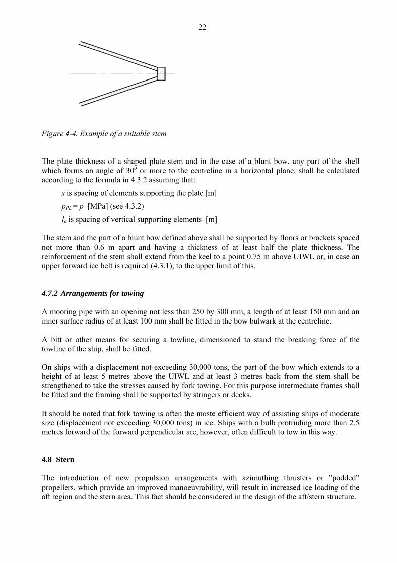
y3c bσ σ τ σ= + = (4.16) 4.7 Bow 4.7.1 Stem The stem shall be made of rolled, cast or forged steel or of shaped steel plates. A sharp edged stem (see Figure 4-4) improves the manoeuvrability of the ship in ice and is recommended particularly for smaller ships with a length under 150 m.
22
Figure 4-4. Example of a suitable stem The plate thickness of a shaped plate stem and in the case of a blunt bow, any part of the shell which forms an angle of 30o or more to the centreline in a horizontal plane, shall be calculated according to the formula in 4.3.2 assuming that:
s is spacing of elements supporting the plate [m]
pPL = p [MPa] (see 4.3.2)
la is spacing of vertical supporting elements [m] The stem and the part of a blunt bow defined above shall be supported by floors or brackets spaced not more than 0.6 m apart and having a thickness of at least half the plate thickness. The reinforcement of the stem shall extend from the keel to a point 0.75 m above UIWL or, in case an upper forward ice belt is required (4.3.1), to the upper limit of this. 4.7.2 Arrangements for towing A mooring pipe with an opening not less than 250 by 300 mm, a length of at least 150 mm and an inner surface radius of at least 100 mm shall be fitted in the bow bulwark at the centreline. A bitt or other means for securing a towline, dimensioned to stand the breaking force of the towline of the ship, shall be fitted. On ships with a displacement not exceeding 30,000 tons, the part of the bow which extends to a height of at least 5 metres above the UIWL and at least 3 metres back from the stem shall be strengthened to take the stresses caused by fork towing. For this purpose intermediate frames shall be fitted and the framing shall be supported by stringers or decks. It should be noted that fork towing is often the moste efficient way of assisting ships of moderate size (displacement not exceeding 30,000 tons) in ice. Ships with a bulb protruding more than 2.5 metres forward of the forward perpendicular are, however, often difficult to tow in this way. 4.8 Stern The introduction of new propulsion arrangements with azimuthing thrusters or ”podded” propellers, which provide an improved manoeuvrability, will result in increased ice loading of the aft region and the stern area. This fact should be considered in the design of the aft/stern structure.
23
An extremely narrow clearance between the propeller blade tip and the stern frame shall be avoided as a small clearance would cause very high loads on the blade tip.
On twin and triple screw ships the ice strengthening of the shell and framing shall be extended to the double bottom for 1.5 metres forward and aft of the side propellers.
Shafting and stern tubes of side propellers shall normally be enclosed within plated bossings. If detached struts are used, their design, strength and attachments to the hull shall be duly considered.
A wide transom stern extending below the UIWL will seriously impede the capability of the ship to back in ice, which is most essential. Therefore a transom stern shall not be extended below the UIWL, if this can be avoided. If unavoidable, the part of the transom below the UIWL shall be kept as narrow as possible. The part of a transom stern situated within the ice belt shall be strengthened as for the midship region.
4.9 Bilge keels Bilge keels are often damaged or ripped off in ice. The connection of bilge keels to the hull shall be so designed that the risk of damage to the hull, in case a bilge keel is ripped off, is minimized. To limit damage when a bilge keel is partly ripped off, it is recommended that bilge keels are cut up into several shorter independent lengths.
5 RUDDER AND STEERING ARRANGEMENTS The scantlings of rudder post, rudder stock, pintles, steering engine etc. as well as the capability of the steering engine shall be determined according to the rules of the Classification Society. The maximum service speed of the ship to be used in these calculations shall, however, not be taken as less than stated below: IA Super 20 knots IA 18 knots IB 16 knots IC 14 knots If the actual maximum service speed of the ship is higher, that speed shall be used. For the ice classes IA Super and IA the rudder stock and the upper edge of the rudder shall be protected against ice pressure by an ice knife or equivalent means. For the ice classes IA Super and IA due regard shall be paid to the excessive load caused by the rudder being forced out of the midship position when backing into an ice ridge. Relief valves for hydraulic pressure shall be effective. The components of the steering gear shall be dimensioned to stand the yield torque of the rudder stock. Where possible, rudder stoppers working on the blade or rudder head shall be fitted.
24
6 PROPULSION MACHINERY
6.1 Scope
These regulations apply to propulsion machinery covering open- and ducted-type propellers with controllable pitch or fixed pitch design for the ice classes IA Super, IA, IB and IC. The given loads are the expected ice loads for the whole ship’s service life under normal operational conditions, including loads resulting from the changing rotational direction of FP propellers. However, these loads do not cover off-design operational conditions, for example when a stopped propeller is dragged through ice. The regulations also apply to azimuthing and fixed thrusters for main propulsion, considering loads resulting from propeller-ice interaction. However, the load models of the regulations do not include propeller/ice interaction loads when ice enters the propeller of a turned azimuthing thruster from the side (radially) or load case when ice block hits on the propeller hub of a pulling propeller. Ice loads resulting from ice impacts on the body of thrusters have to be estimated, but ice load formulae are not available.
6.2 Symbols
c m chord length of blade section
7.0c m chord length of blade section at 0.7R propeller radius CP controllable pitch D m propeller diameter d m external diameter of propeller hub (at propeller plane)
limitD m limit value for propeller diameter EAR expanded blade area ratio
bF kN maximum backward blade force for the ship’s service life
exF kN ultimate blade load resulting from blade loss through plastic bending
fF kN maximum forward blade force for the ship’s service life Fice kN ice load (Fice)max kN maximum ice load for the ship’s service life FP fixed pitch
0h m depth of the propeller centreline from lower ice waterline Hice m thickness of maximum design ice block entering to propeller I kgm2 equivalent mass moment of inertia of all parts on engine side of
component under consideration tI kgm2 equivalent mass moment of inertia of the whole propulsion system
k shape parameter for Weibull distribution LIWL m lower ice waterline m slope for SN curve in log/log scale
BLM kNm blade bending moment MCR maximum continuous rating n rev./s propeller rotational speed nn rev./s nominal propeller rotational speed at MCR in free running condition
classN reference number of impacts per propeller rotational speed per ice class
iceN total number of ice loads on propeller blade for the ship’s service life NR reference number of load for equivalent fatigue stress (108 cycles)
25
NQ number of propeller revolutions during a milling sequence
7.0P m propeller pitch at 0.7R radius P0.7n m propeller pitch at 0.7R radius at MCR in free running condition P0.7b m propeller pitch at 0.7R radius at MCR in bollard condition Q kNm Torque
emaxQ kNm maximum engine torque
maxQ kNm maximum torque on the propeller resulting from propeller-ice interaction Q motor kNm electric motor peak torque
nQ kNm nominal torque at MCR in free running condition Qr kNm maximum response torque along the propeller shaft line
smaxQ kNm maximum spindle torque of the blade for the ship’s service life R m propeller radius r m blade section radius T kN propeller thrust
bT kN maximum backward propeller ice thrust for the ship’s service life
fT kN maximum forward propeller ice thrust for the ship’s service life
nT kN propeller thrust at MCR in free running condition Tr kN maximum response thrust along the shaft line t m maximum blade section thickness Z number of propeller blades αi [deg] duration of propeller blade/ice interaction expressed in rotation angle εγ the reduction factor for fatigue; scatter and test specimen size effect
νγ the reduction factor for fatigue; variable amplitude loading effect
mγ the reduction factor for fatigue; mean stress effect ρ a reduction factor for fatigue correlating the maximum stress amplitude
to the equivalent fatigue stress for 108 stress cycles 2.0σ MPa proof yield strength of blade material
expσ MPa mean fatigue strength of blade material at 108 cycles to failure in sea water
fatσ MPa equivalent fatigue ice load stress amplitude for 108 stress cycles
flσ MPa characteristic fatigue strength for blade material
refσ MPa reference stress uref σσσ ⋅+⋅= 4.06.0 2.0
2refσ MPa reference stress uref σσ ⋅= 7.02 or
uref σσσ ⋅+⋅= 4.06.0 2.02 whichever is less
stσ MPa maximum stress resulting from Fb or fF
uσ MPa ultimate tensile strength of blade material ( )bmaxiceσ MPa principal stress caused by the maximum backward propeller ice load ( ) fmaxiceσ MPa principal stress caused by the maximum forward propeller ice load
( )maxiceσ MPa maximum ice load stress amplitude
26
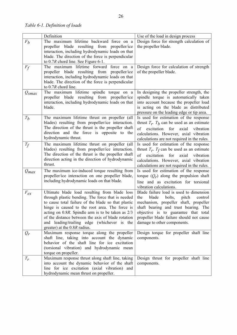
Table 6-1. Definition of loads Definition Use of the load in design process Fb The maximum lifetime backward force on a
propeller blade resulting from propeller/ice interaction, including hydrodynamic loads on that blade. The direction of the force is perpendicular to 0.7R chord line. See Figure 6-1.
Design force for strength calculation of the propeller blade.
Ff The maximum lifetime forward force on a propeller blade resulting from propeller/ice interaction, including hydrodynamic loads on that blade. The direction of the force is perpendicular to 0.7R chord line.
Design force for calculation of strength of the propeller blade.
Qsmax The maximum lifetime spindle torque on a propeller blade resulting from propeller/ice interaction, including hydrodynamic loads on that blade.
In designing the propeller strength, the spindle torque is automatically taken into account because the propeller load is acting on the blade as distributed pressure on the leading edge or tip area.
Tb The maximum lifetime thrust on propeller (all blades) resulting from propeller/ice interaction. The direction of the thrust is the propeller shaft direction and the force is opposite to the hydrodynamic thrust.
Is used for estimation of the response thrust Tr. Tb can be used as an estimate of excitation for axial vibration calculations. However, axial vibration calculations are not required in the rules.
Tf The maximum lifetime thrust on propeller (all blades) resulting from propeller/ice interaction. The direction of the thrust is the propeller shaft direction acting in the direction of hydrodynamic thrust.
Is used for estimation of the response thrust Tr. Tf can be used as an estimate of excitation for axial vibration calculations. However, axial vibration calculations are not required in the rules.
Qmax The maximum ice-induced torque resulting from propeller/ice interaction on one propeller blade, including hydrodynamic loads on that blade.
Is used for estimation of the response torque (Qr) along the propulsion shaft line and as excitation for torsional vibration calculations.
Fex Ultimate blade load resulting from blade loss through plastic bending. The force that is needed to cause total failure of the blade so that plastic hinge is caused to the root area. The force is acting on 0.8R. Spindle arm is to be taken as 2/3 of the distance between the axis of blade rotation and leading/trailing edge (whichever is the greater) at the 0.8R radius.
Blade failure load is used to dimension the blade bolts, pitch control mechanism, propeller shaft, propeller shaft bearing and trust bearing. The objective is to guarantee that total propeller blade failure should not cause damage to other components.
Qr Maximum response torque along the propeller shaft line, taking into account the dynamic behavior of the shaft line for ice excitation (torsional vibration) and hydrodynamic mean torque on propeller.
Design torque for propeller shaft line components.
Tr Maximum response thrust along shaft line, taking into account the dynamic behavior of the shaft line for ice excitation (axial vibration) and hydrodynamic mean thrust on propeller.
Design thrust for propeller shaft line components.
27
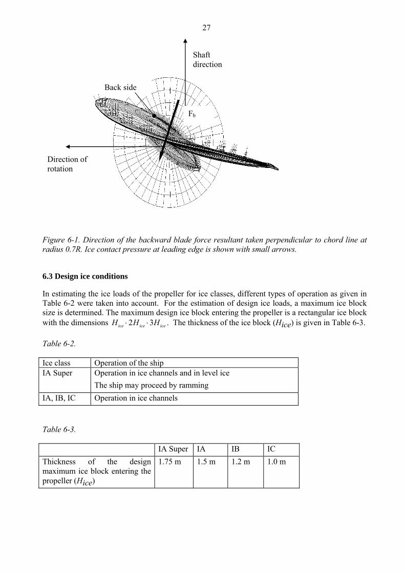
Figure 6-1. Direction of the backward blade force resultant taken perpendicular to chord line at radius 0.7R. Ice contact pressure at leading edge is shown with small arrows.
6.3 Design ice conditions
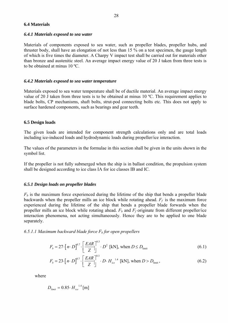
In estimating the ice loads of the propeller for ice classes, different types of operation as given in Table 6-2 were taken into account. For the estimation of design ice loads, a maximum ice block size is determined. The maximum design ice block entering the propeller is a rectangular ice block with the dimensions 2 3ice ice iceH H H⋅ ⋅ . The thickness of the ice block (Hice) is given in Table 6-3. Table 6-2. Ice class Operation of the ship IA Super Operation in ice channels and in level ice
The ship may proceed by ramming IA, IB, IC Operation in ice channels Table 6-3. IA Super IA IB IC Thickness of the design maximum ice block entering the propeller (Hice)
1.75 m 1.5 m 1.2 m 1.0 m
Back side
Shaft direction
Fb
Direction of rotation
28
6.4 Materials
6.4.1 Materials exposed to sea water Materials of components exposed to sea water, such as propeller blades, propeller hubs, and thruster body, shall have an elongation of not less than 15 % on a test specimen, the gauge length of which is five times the diameter. A Charpy V impact test shall be carried out for materials other than bronze and austenitic steel. An average impact energy value of 20 J taken from three tests is to be obtained at minus 10 ºC. 6.4.2 Materials exposed to sea water temperature Materials exposed to sea water temperature shall be of ductile material. An average impact energy value of 20 J taken from three tests is to be obtained at minus 10 ºC. This requirement applies to blade bolts, CP mechanisms, shaft bolts, strut-pod connecting bolts etc. This does not apply to surface hardened components, such as bearings and gear teeth.
6.5 Design loads
The given loads are intended for component strength calculations only and are total loads including ice-induced loads and hydrodynamic loads during propeller/ice interaction. The values of the parameters in the formulae in this section shall be given in the units shown in the symbol list. If the propeller is not fully submerged when the ship is in ballast condition, the propulsion system shall be designed according to ice class IA for ice classes IB and IC. 6.5.1 Design loads on propeller blades Fb is the maximum force experienced during the lifetime of the ship that bends a propeller blade backwards when the propeller mills an ice block while rotating ahead. Ff is the maximum force experienced during the lifetime of the ship that bends a propeller blade forwards when the propeller mills an ice block while rotating ahead. Fb and Ff originate from different propeller/ice interaction phenomena, not acting simultaneously. Hence they are to be applied to one blade separately. 6.5.1.1 Maximum backward blade force Fb for open propellers
[ ]0.3
0.7 2limit27 [kN], when b
EARF n D D D DZ
⎡ ⎤= ⋅ ⋅ ⋅ ⋅ ≤⎢ ⎥⎣ ⎦ (6.1)
[ ]0.3
0.7 1.4limit23 [kN], when b ice
EARF n D D H D DZ
⎡ ⎤= ⋅ ⋅ ⋅ ⋅ ⋅ >⎢ ⎥⎣ ⎦, (6.2)
where
4.185.0 icelimit HD ⋅= [m]
29
n is the nominal rotational speed (at MCR in free running condition) for a CP propeller and 85% of the nominal rotational speed (at MCR in free running condition) for an FP propeller.
6.5.1.2 Maximum forward blade force Ff for open propellers
2limit250 [kN], when f
EARF D D DZ
⎡ ⎤= ⋅ ⋅ ≤⎢ ⎥⎣ ⎦ (6.3)
limit1500 [kN], when
1f ice
EARF D H D DdZD
⎡ ⎤= ⋅ ⋅ ⋅ ⋅ >⎢ ⎥ ⎛ ⎞⎣ ⎦ −⎜ ⎟⎝ ⎠
(6.4)
where
icelimit H
Dd
D ⋅⎟⎠⎞
⎜⎝⎛ −
=1
2 [m].
6.5.1.3 Loaded area on the blade for open propellers Load cases 1-4 have to be covered, as given in Table 6-4 below, for CP and FP propellers. In order to obtain blade ice loads for a reversing propeller, load case 5 also has to be covered for FP propellers.
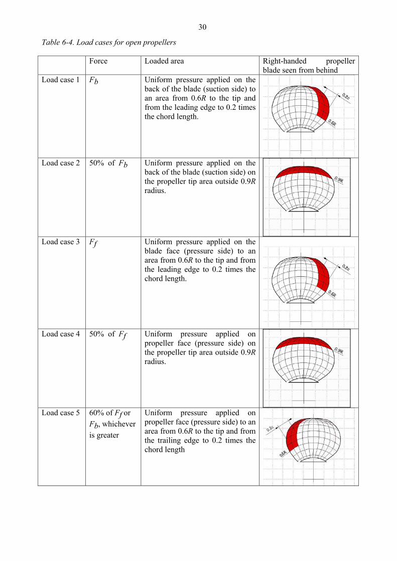
30
Table 6-4. Load cases for open propellers Force Loaded area Right-handed propeller
blade seen from behind Load case 1 Fb Uniform pressure applied on the
back of the blade (suction side) to an area from 0.6R to the tip and from the leading edge to 0.2 times the chord length.
Load case 2 50% of Fb Uniform pressure applied on the back of the blade (suction side) on the propeller tip area outside 0.9R radius.
Load case 3 Ff Uniform pressure applied on the
blade face (pressure side) to an area from 0.6R to the tip and from the leading edge to 0.2 times the chord length.
Load case 4
50% of Ff Uniform pressure applied on propeller face (pressure side) on the propeller tip area outside 0.9R radius.
Load case 5 60% of Ff or
Fb, whichever is greater
Uniform pressure applied on propeller face (pressure side) to an area from 0.6R to the tip and from the trailing edge to 0.2 times the chord length
31
6.5.1.4 Maximum backward blade ice force Fb for ducted propellers
[ ]0.3
0.7 2limit9.5 [kN], when b
EARF n D D D DZ
⎡ ⎤= ⋅ ⋅ ⋅ ⋅ ≤⎢ ⎥⎣ ⎦ (6.5)
[ ]0.3
0.7 0.6 1.4limit66 [kN], when b ice
EARF n D D H D DZ
⎡ ⎤= ⋅ ⋅ ⋅ ⋅ ⋅ >⎢ ⎥⎣ ⎦, (6.6)
where
icelimit HD ⋅= 4 [m]
n is the nominal rotational speed (at MCR in free running condition) for a CP propeller and 85% of the nominal rotational speed (at MCR in free running condition) for an FP propeller.
6.5.1.5 Maximum forward blade ice force Ff for ducted propellers
2limit250 [kN], when f
EARF D D DZ
⎡ ⎤= ⋅ ⋅ ≤⎢ ⎥⎣ ⎦ (6.7)
limit1500 [kN], when
1f ice
EARF D H D DdZD
⎡ ⎤= ⋅ ⋅ ⋅ ⋅ >⎢ ⎥ ⎛ ⎞⎣ ⎦ −⎜ ⎟⎝ ⎠
(6.8)
where
icelimit H
Dd
D ⋅⎟⎠⎞
⎜⎝⎛ −
=1
2 [m].
6.5.1.6 Loaded area on the blade for ducted propellers Load cases 1 and 3 have to be covered as given in Table 6-5 for all propellers, and an additional load case (load case 5) for an FP propeller, to cover ice loads when the propeller is reversed.
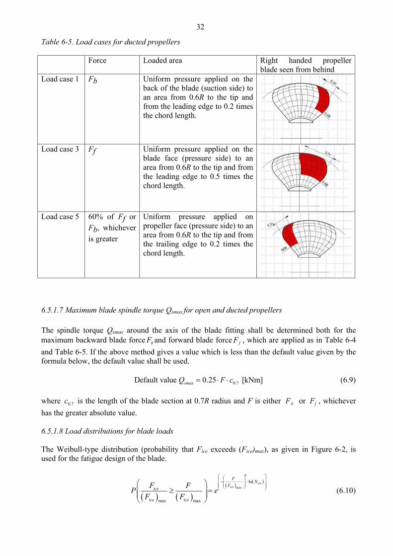
32
Table 6-5. Load cases for ducted propellers Force Loaded area Right handed propeller
blade seen from behind Load case 1 Fb Uniform pressure applied on the
back of the blade (suction side) to an area from 0.6R to the tip and from the leading edge to 0.2 times the chord length.
Load case 3 Ff Uniform pressure applied on the blade face (pressure side) to an area from 0.6R to the tip and from the leading edge to 0.5 times the chord length.
Load case 5 60% of Ff or
Fb, whichever is greater
Uniform pressure applied on propeller face (pressure side) to an area from 0.6R to the tip and from the trailing edge to 0.2 times the chord length.
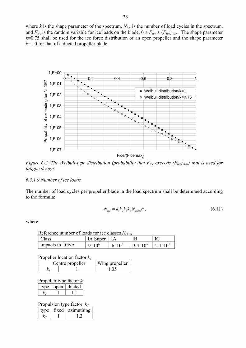
6.5.1.7 Maximum blade spindle torque Qsmax for open and ducted propellers The spindle torque Qsmax around the axis of the blade fitting shall be determined both for the maximum backward blade force bF and forward blade force fF , which are applied as in Table 6-4 and Table 6-5. If the above method gives a value which is less than the default value given by the formula below, the default value shall be used. 0.7Default value 0.25 [kNm]smaxQ F c= ⋅ ⋅ (6.9) where 7.0c is the length of the blade section at 0.7R radius and F is either Fb or Ff , whichever has the greater absolute value. 6.5.1.8 Load distributions for blade loads The Weibull-type distribution (probability that Fice exceeds (Fice)max), as given in Figure 6-2, is used for the fatigue design of the blade.
( ) ( )
( ) ( )max
ln
max max
k
iceice
F NF
ice
ice ice
F FP eF F
⎛ ⎞⎛ ⎞⎜ ⎟⎜ ⎟− ⋅⎜ ⎟⎜ ⎟⎜ ⎟⎝ ⎠⎝ ⎠⎛ ⎞
≥ =⎜ ⎟⎜ ⎟⎝ ⎠
(6.10)
33
where k is the shape parameter of the spectrum, Nice is the number of load cycles in the spectrum, and Fice is the random variable for ice loads on the blade, 0 ≤ Fice ≤ (Fice)max. The shape parameter k=0.75 shall be used for the ice force distribution of an open propeller and the shape parameter k=1.0 for that of a ducted propeller blade.
1,E-07
1,E-06
1,E-05
1,E-04
1,E-03
1,E-02
1,E-01
1,E+000 0,2 0,4 0,6 0,8 1
Fice/(Ficemax)
Pro
pabi
lity
of e
xcee
ding
for N
=1E7
Weibull distribution/k=1Weibull distribution/k=0.75
Figure 6-2. The Weibull-type distribution (probability that Fice exceeds (Fice)max) that is used for fatigue design. 6.5.1.9 Number of ice loads The number of load cycles per propeller blade in the load spectrum shall be determined according to the formula: 1 2 3 4ice classN k k k k N n= , (6.11) where
Reference number of loads for ice classes Nclass Class IA Super IA IB IC impacts in life/n 6109 ⋅ 6106 ⋅ 6104.3 ⋅ 6101.2 ⋅
Propeller location factor k1
Centre propeller Wing propellerk1 1 1.35
Propeller type factor k2 type open ducted k2 1 1.1
Propulsion type factor k3 type fixed azimuthing k3 1 1.2
34
The submersion factor k4 is determined from the equation
4 = 0.8 - when 0 = 0.8 - 0.4· when 0 1 = 0.6 - 0.2· when 1 2.5 = 0.1 when 2.5
k f ff ff f
f
<≤ ≤< ≤>
(6.12)
where the immersion function f is:
1/ 2
o iceh HfD−
= − , (6.13)
where oh is the depth of the propeller centreline at the lower ice waterline (LIWL) of the ship.
For components that are subject to loads resulting from propeller/ice interaction with all the propeller blades, the number of load cycles (Nice) is to be multiplied by the number of propeller blades (Z). 6.5.2 Axial design loads for open and ducted propellers
6.5.2.1 Maximum ice thrust on propeller Tf and Tb for open and ducted propellers The maximum forward and backward ice thrusts are: 1.1 [kN]f fT F= ⋅ (6.14) 1.1 [kN]b bT F= ⋅ (6.15)
6.5.2.2 Design thrust along the propulsion shaft line for open and ducted propellers The design thrust along the propeller shaft line is to be calculated with the formulae below. The greater value of the forward and backward direction loads shall be taken as the design load for both directions. The factors 2.2 and 1.5 take into account the dynamic magnification resulting from axial vibration. In a forward direction 2.2 [kN]r fT T T= + ⋅ (6.16) In a backward direction 1.5 [kN]r bT T= ⋅ (6.17)
35
If the hydrodynamic bollard thrust, T, is not known, T is to be taken as follows: Propeller type T CP propellers (open) 1.25 Tn CP propellers (ducted) 1.1 Tn FP propellers driven by turbine or electric motor Tn FP propellers driven by diesel engine (open) 0.85 Tn FP propellers driven by diesel engine (ducted) 0.75 Tn Here, Tn is the nominal propeller thrust at MCR in free running open water condition. 6.5.3 Torsional design loads
6.5.3.1 Design ice torque on propeller Qmax for open propellers Qmax is the maximum torque on a propeller resulting from ice/propeller interaction.
( )0.16
0.17 30.7limit10.9 1 [kNm], when max
PdQ nD D D DD D
⎡ ⎤⎡ ⎤= ⋅ − ⋅ ⋅ ⋅ ≤⎢ ⎥⎢ ⎥⎣ ⎦ ⎣ ⎦ (6.18)
( )0.16
0.17 1.9 1.10.720.7 1max icePdQ nD D H
D D⎡ ⎤⎡ ⎤= ⋅ − ⋅ ⋅ ⋅ ⋅⎢ ⎥⎢ ⎥⎣ ⎦ ⎣ ⎦
[kNm], when limitDD > , (6.19)
where
icelimit HD ⋅= 8.1 [m].
n is the rotational propeller speed in bollard condition. If not known, n is to be taken as follows:
Propeller type Rotational speed n CP propellers nn FP propellers driven by turbine or electric motor nn FP propellers driven by diesel engine 0.85 nn
Here, nn is the nominal rotational speed at MCR in free running condition.
For CP propellers, the propeller pitch, P0.7 shall correspond to MCR in bollard condition. If not known, P0.7 is to be taken as 0.7⋅P0.7n, where P0.7n is the propeller pitch at MCR in free running condition.
6.5.3.2 Design ice torque on propeller Qmax for ducted propellers Qmax is the maximum torque on a propeller resulting from ice/propeller interaction.
( )0.16
0.17 30.77.7 1maxPdQ nD D
D D⎡ ⎤⎡ ⎤= ⋅ − ⋅ ⋅ ⋅⎢ ⎥⎢ ⎥⎣ ⎦ ⎣ ⎦
[kNm] when limitDD ≤ , (6.20)
( )0.16
0.17 1.9 1.10.714.6 1max icePdQ nD D H
D D⎡ ⎤⎡ ⎤= ⋅ − ⋅ ⋅ ⋅ ⋅⎢ ⎥⎢ ⎥⎣ ⎦ ⎣ ⎦
[kNm] when limitDD > , (6.21)
36
where
icelimit HD ⋅= 8.1 ·[m]. n is the rotational propeller speed in bollard condition. If not known, n is to be taken as follows:
Propeller type Rotational speed n CP propellers nn FP propellers driven by turbine or electric motor nn FP propellers driven by diesel engine 0.85 nn
Here, nn is the nominal rotational speed at MCR, free running condition.
For CP propellers, the propeller pitch, P0.7 shall correspond to MCR in bollard condition. If not known, P0.7 is to be taken as 0.7⋅P0.7n , where P0.7n is the propeller pitch at MCR in free running condition.
6.5.3.3 Ice torque excitation for open and ducted propellers The propeller ice torque excitation for shaft line transient torsional vibration analysis shall be described by a sequence of blade impacts which are of a half sine shape; see Figure 6-3. The torque resulting from a single blade ice impact as a function of the propeller rotation angle is then
( )( )max
i
( ) sin 180 / , when 0...
( ) 0, when = ...360q i iQ C Q
Q
ϕ ϕ α ϕ α
ϕ ϕ α
= ⋅ ⋅ =
= (6.22)
where the Cq and iα parameters are given in the table below. iα is duration of propeller blade/ice interaction expressed in propeller rotation angle. Torque excitation Propeller/ice
interaction Cq iα
Case 1 Single ice block 0.75 90 Case 2 Single ice block 1.0 135 Case 3 Two ice blocks
(phase shift 360/2/Z deg.)
0.5 45
The total ice torque is obtained by summing the torque of single blades, taking into account the phase shift 360deg./Z. In addition, at the beginning and at the end of the milling sequence a linear ramp functions for 270 degrees of rotation angle shall be used. The number of propeller revolutions during a milling sequence shall be obtained with the formula: 2Q iceN H= ⋅ (6.23)
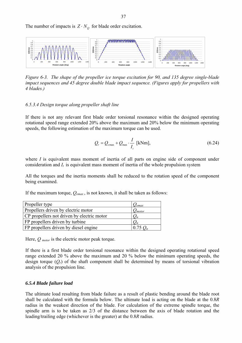
37
The number of impacts is QNZ ⋅ for blade order excitation.
00,10,20,30,40,50,60,70,80,9
1
0 200 400 600 800 1000 1200 1400
Rotaion angle [deg]
Q/Q
max
00,10,20,30,40,50,60,70,80,9
1
0 200 400 600 800 1000 1200 1400
Rotation angle
Q/Q
max
00,10,20,30,40,50,60,70,80,9
1
0 200 400 600 800 1000 1200 1400
Rotation angle [deg]
Q/Q
max
Figure 6-3. The shape of the propeller ice torque excitation for 90, and 135 degree single-blade impact sequences and 45 degree double blade impact sequence. (Figures apply for propellers with 4 blades.)
6.5.3.4 Design torque along propeller shaft line If there is not any relevant first blade order torsional resonance within the designed operating rotational speed range extended 20% above the maximum and 20% below the minimum operating speeds, the following estimation of the maximum torque can be used.
max maxr et
IQ Q QI
= + ⋅ [kNm], (6.24)
where I is equivalent mass moment of inertia of all parts on engine side of component under consideration and It is equivalent mass moment of inertia of the whole propulsion system All the torques and the inertia moments shall be reduced to the rotation speed of the component being examined. If the maximum torque, Qemax , is not known, it shall be taken as follows: Propeller type Qemax Propellers driven by electric motor Qmotor CP propellers not driven by electric motor Qn FP propellers driven by turbine Qn FP propellers driven by diesel engine 0.75 Qn Here, Q motor is the electric motor peak torque. If there is a first blade order torsional resonance within the designed operating rotational speed range extended 20 % above the maximum and 20 % below the minimum operating speeds, the design torque (Qr) of the shaft component shall be determined by means of torsional vibration analysis of the propulsion line. 6.5.4 Blade failure load The ultimate load resulting from blade failure as a result of plastic bending around the blade root shall be calculated with the formula below. The ultimate load is acting on the blade at the 0.8R radius in the weakest direction of the blade. For calculation of the extreme spindle torque, the spindle arm is to be taken as 2/3 of the distance between the axis of blade rotation and the leading/trailing edge (whichever is the greater) at the 0.8R radius.
38
2300
0.8 2ref
ex
c tF
D rσ⋅ ⋅ ⋅
=⋅ − ⋅
[kN], (6.25)
where
uref σσσ ⋅+⋅= 4.06.0 2.0
c, t, and r are, respectively, the length, thickness, and radius of the cylindrical root section of the blade at the weakest section outside the root filet.
6.6 Design
6.6.1 Design principle The strength of the propulsion line shall be designed according to the pyramid strength principle. This means that the loss of the propeller blade shall not cause any significant damage to other propeller shaft line components. 6.6.2 Propeller blade
6.6.2.1 Calculation of blade stresses The blade stresses shall be calculated for the design loads given in Section 6.5.1. Finite element analysis shall be used for stress analysis for final approval for all propellers. The following simplified formulae can be used in estimating the blade stresses for all propellers at the root area (r/R < 0.5). The root area dimensions based on formula (6.26) can be accepted even if the FEM analysis would show greater stresses at the root area.
1 2100BL
stMC
ctσ =
⋅ [MPa], (6.26)
where
constant C1 is the actual stressstress obtained with beam equation
. If the actual value is not available,
C1 should be taken as 1.6.
FRRrM BL **)/75.0( −= , for relative radius r/R < 0.5 F is the maximum of Fb and Ff, whichever is greater.
6.6.2.2 Acceptability criterion The following criterion for calculated blade stresses has to be fulfilled.
39
2 1.5ref
st
σσ
≥ (6.27)
where
stσ is the calculated stress for the design loads. If FEM analysis is used in estimating the stresses, von Mises stresses shall be used
2refσ is the reference stress, defined as:
uref σσ ⋅= 7.02 or
uref σσσ ⋅+⋅= 4.06.0 2.02 , whichever is less.
6.6.2.3 Fatigue design of propeller blade The fatigue design of the propeller blade is based on an estimated load distribution for the service life of the ship and the S-N curve for the blade material. An equivalent stress that produces the same fatigue damage as the expected load distribution shall be calculated and the acceptability criterion for fatigue should be fulfilled as given in this section. The equivalent stress is normalised for 100 million cycles. If the following criterion is fulfilled fatigue calculations according to this chapter are not required. 32
exp 1 2 log( )BBref iceB Nσ σ≥ ⋅ ⋅ (6.28)
where B1, B2 and B3 coefficients for open and ducted propellers are given in the table below.
Open propeller Ducted propeller
B1 0.00270 0.00184 B2 1.007 1.007 B3 2.101 2.470
For calculation of equivalent stress two types of SN curves are available.
1. Two slope SN curve (slopes 4.5 and 10), see Figure 6-4. 2. One slope SN curve( the slope can be chosen), see Figure 6-5.
The type of the SN-curve shall be selected to correspond to the material properties of the blade. If SN-curve is not known the two slope SN curve shall be used.
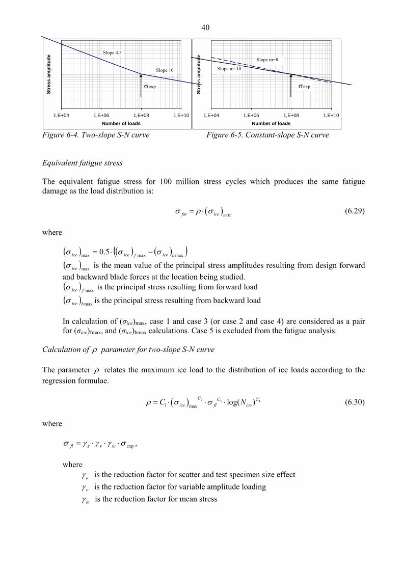
40
1,E+04 1,E+06 1,E+08 1,E+10Number of loads
Stre
ss a
mpl
itude
Slope 4.5
Slope 10
σexp
1,E+04 1,E+06 1,E+08 1,E+10Number of loads
Stre
ss a
mpl
itude Slope m=8
Slope m=10
σexp
Figure 6-4. Two-slope S-N curve Figure 6-5. Constant-slope S-N curve Equivalent fatigue stress The equivalent fatigue stress for 100 million stress cycles which produces the same fatigue damage as the load distribution is: ( )fat ice max
σ ρ σ= ⋅ (6.29) where
( ) ( ) ( )( )maxmaxmax 5.0 biceficeice σσσ −⋅=
( )maxiceσ is the mean value of the principal stress amplitudes resulting from design forward and backward blade forces at the location being studied. ( ) maxficeσ is the principal stress resulting from forward load
( ) maxbiceσ is the principal stress resulting from backward load In calculation of (σice)max, case 1 and case 3 (or case 2 and case 4) are considered as a pair for (σice)fmax, and (σice)bmax calculations. Case 5 is excluded from the fatigue analysis.
Calculation of ρ parameter for two-slope S-N curve The parameter ρ relates the maximum ice load to the distribution of ice loads according to the regression formulae. ( ) 2 3 4
1 maxlog( )C C C
ice fl iceC Nρ σ σ= ⋅ ⋅ ⋅ (6.30) where
expσγγγσ ε ⋅⋅⋅= mvfl , where
εγ is the reduction factor for scatter and test specimen size effect
νγ is the reduction factor for variable amplitude loading
mγ is the reduction factor for mean stress
41
expσ is the mean fatigue strength of the blade material at 108 cycles to failure in seawater. The following values should be used for the reduction factors if actual values are not available: εγ = 0.67, νγ = 0.75, and mγ = 0.75.
The coefficients 1C , 2C , 3C , and 4C are given in Table 6-6.
Table 6-6.
Open propeller Ducted propeller 1C 0.000711 0.000509
2C 0.0645 0.0533
3C -0.0565 -0.0459
4C 2.22 2.584 Calculation of ρ parameter for constant-slope S-N curve For materials with a constant-slope S-N curve - see Figure 6-5 - the ρ factor shall be calculated with the following formula:
1/
1(ln( ))
m
ice kice
R
NG NN
ρ −⎛ ⎞= ⎜ ⎟⎝ ⎠
, (6.31)
where
k is the shape parameter of the Weibull distribution k = 1.0 for ducted propellers and k = 0.75 for open propellers. RN is the reference number of load cycles (=100 million) Values for the G parameter are given in Table 6-7. Linear interpolation may be used to calculate the G value for other m/k ratios than given in the Table 6-7. Table 6-7. Value for the G parameter for different m/k ratios m/k G m/k G m/k G 3 6 5.5 287.9 8 40320 3.5 11.6 6 720 8.5 119292 4 24 6.5 1871 9 362880 4.5 52.3 7 5040 9.5 1.133E6 5 120 7.5 14034 10 3.623E6
6.6.2.4 Acceptability criterion for fatigue The equivalent fatigue stress at all locations on the blade has to fulfil the following acceptability criterion:
42
1.5fl
fat
σσ
≥ (6.32)
where
expσγγγσ ε ⋅⋅⋅= mvfl ,
where
εγ is the reduction factor for scatter and test specimen size effect
νγ is the reduction factor for variable amplitude loading
mγ is the reduction factor for mean stress
expσ is the mean fatigue strength of the blade material at 108 cycles to failure in seawater. The following values should be used for the reduction factors if actual values are not available: εγ = 0.67, νγ = 0.75, and mγ = 0.75.
6.6.3 Propeller bossing and CP mechanism The blade bolts, the CP mechanism, the propeller boss, and the fitting of the propeller to the propeller shaft shall be designed to withstand the maximum and fatigue design loads, as defined in Section 6.5. The safety factor against yielding shall be greater than 1.3 and that against fatigue greater than 1.5. In addition, the safety factor for loads resulting from loss of the propeller blade through plastic bending as defined in Section 6.5.4 shall be greater than 1.0 against yielding. 6.6.4 Propulsion shaft line The shafts and shafting components, such as the thrust and stern tube bearings, couplings, flanges and sealings, shall be designed to withstand the propeller/ice interaction loads as given in Section 6.5. The safety factor is to be at least 1.3.
6.6.4.1 Shafts and shafting components The ultimate load resulting from total blade failure as defined in Section 6.5.4 should not cause yielding in shafts and shaft components. The loading shall consist of the combined axial, bending, and torsion loads, wherever this is significant. The minimum safety factor against yielding is to be 1.0 for bending and torsional stresses. 6.6.5 Azimuthing main propulsors In addition to the above requirements, special consideration shall be given to those loading cases which are extraordinary for propulsion units when compared with conventional propellers. The estimation of loading cases has to reflect the way of operation of the ship and the thrusters. In this respect, for example, the loads caused by the impacts of ice blocks on the propeller hub of a pulling propeller have to be considered. Furthermore, loads resulting from the thrusters operating at an oblique angle to the flow have to be considered. The steering mechanism, the fitting of the unit, and the body of the thruster shall be designed to withstand the loss of a blade without damage. The loss of a blade shall be considered for the propeller blade orientation which causes
43
the maximum load on the component being studied. Typically, top-down blade orientation places the maximum bending loads on the thruster body. Azimuth thrusters shall also be designed for estimated loads caused by thruster body/ice interaction. The thruster body has to stand the loads obtained when the maximum ice blocks, which are given in Section 6.3, strike the thruster body when the ship is at a typical ice operating speed. In addition, the design situation in which an ice sheet glides along the ship’s hull and presses against the thruster body should be considered. The thickness of the sheet should be taken as the thickness of the maximum ice block entering the propeller, as defined in Section 6.3.
6.6.6 Vibrations
The propulsion system shall be designed in such a way that the complete dynamic system is free from harmful torsional, axial, and bending resonances at a 1-order blade frequency within the designed running speed range, extended by 20 per cent above and below the maximum and minimum operating rotational speeds. If this condition cannot be fulfilled, a detailed vibration analysis has to be carried out in order to determine that the acceptable strength of the components can be achieved.
6.7 Alternative design procedure
6.7.1 Scope As an alternative to Sections 6.5 and 6.6, a comprehensive design study may be carried out to the satisfaction of the Administration or the classification society. The study has to be based on ice conditions given for different ice classes in Section 6.3. It has to include both fatigue and maximum load design calculations and fulfil the pyramid strength principle, as given in Section 6.6.1. 6.7.2 Loading Loads on the propeller blade and propulsion system shall be based on an acceptable estimation of hydrodynamic and ice loads. 6.7.3 Design levels The analysis is to indicate that all components transmitting random (occasional) forces, excluding propeller blade, are not subjected to stress levels in excess of the yield stress of the component material, with a reasonable safety margin. Cumulative fatigue damage calculations are to indicate a reasonable safety factor. Due account is to be taken of material properties, stress raisers, and fatigue enhancements. Vibration analysis is to be carried out and is to indicate that the complete dynamic system is free from harmful torsional resonances resulting from propeller/ice interaction.
44
7 MISCELLANEOUS MACHINERY REQUIREMENTS 7.1 Starting arrangements The capacity of the air receivers shall be sufficient to provide without reloading not less than 12 consecutive starts of the propulsion engine, if this has to be reversed for going astern, or 6 consecutive starts if the propulsion engine does not have to be reversed for going astern. If the air receivers serve any other purposes than starting the propulsion engine, they shall have additional capacity sufficient for these purposes. The capacity of the air compressors shall be sufficient for charging the air receivers from atmo-spheric to full pressure in one (1) hour, except for a ship with the ice class IA Super, if its pro-pulsion engine has to be reversed for going astern, in which case the compressor shall be able to charge the receivers in half an hour.
7.2 Sea inlet and cooling water systems The cooling water system shall be designed to ensure supply of cooling water when navigating in ice. For this purpose at least one cooling water inlet chest shall be arranged as follows:
1. The sea inlet shall be situated near the centreline of the ship and well aft if possible. 2. As guidance for design the volume of the chest shall be about one cubic metre for every
750 kW engine output of the ship including the output of auxiliary engines necessary for the ship's service.
3. The chest shall be sufficiently high to allow ice to accumulate above the inlet pipe.
4. A pipe for discharge cooling water, allowing full capacity discharge, shall be connected to
the chest.
5. The open area of the strainer plates shall not be less than four (4) times the inlet pipe sectional area.
If there are difficulties to meet the requirements of paragraphs 2 and 3 above, two smaller chests may be arranged for alternating intake and discharge of cooling water. Otherwise the arrangement and situation shall be as above. Heating coils may be installed in the upper part of the sea chest. Arrangements for using ballast water for cooling purposes may be useful as a reserve in ballast condition but cannot be accepted as a substitute for sea inlet chest as described above.
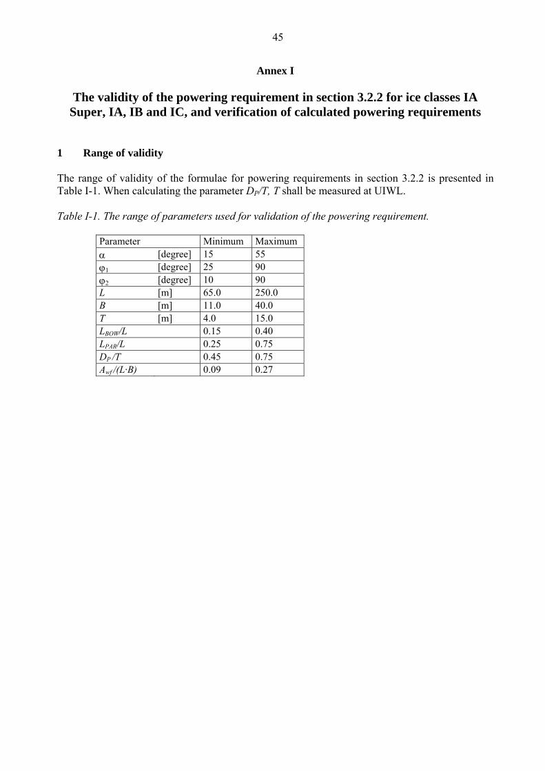
45
Annex I
The validity of the powering requirement in section 3.2.2 for ice classes IA
Super, IA, IB and IC, and verification of calculated powering requirements 1 Range of validity The range of validity of the formulae for powering requirements in section 3.2.2 is presented in Table I-1. When calculating the parameter DP/T, T shall be measured at UIWL. Table I-1. The range of parameters used for validation of the powering requirement.
Parameter Minimum Maximum α [degree] 15 55 ϕ1 [degree] 25 90 ϕ2 [degree] 10 90 L [m] 65.0 250.0 B [m] 11.0 40.0 T [m] 4.0 15.0 LBOW/L 0.15 0.40 LPAR/L 0.25 0.75 DP /T 0.45 0.75 Awf /(L·B) 0.09 0.27
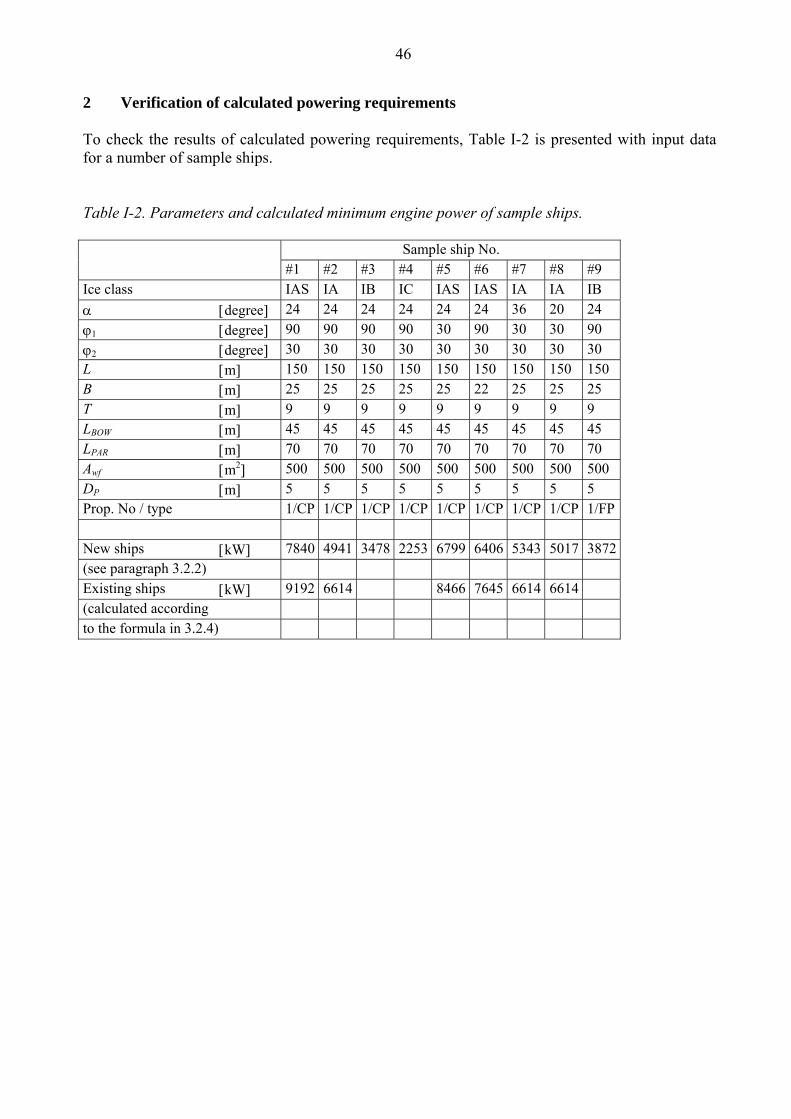
46
2 Verification of calculated powering requirements To check the results of calculated powering requirements, Table I-2 is presented with input data for a number of sample ships. Table I-2. Parameters and calculated minimum engine power of sample ships. Sample ship No. #1 #2 #3 #4 #5 #6 #7 #8 #9 Ice class IAS IA IB IC IAS IAS IA IA IB α [degree] 24 24 24 24 24 24 36 20 24 ϕ1 [degree] 90 90 90 90 30 90 30 30 90 ϕ2 [degree] 30 30 30 30 30 30 30 30 30 L [m] 150 150 150 150 150 150 150 150 150 B [m] 25 25 25 25 25 22 25 25 25 T [m] 9 9 9 9 9 9 9 9 9 LBOW [m] 45 45 45 45 45 45 45 45 45 LPAR [m] 70 70 70 70 70 70 70 70 70 Awf [m2] 500 500 500 500 500 500 500 500 500 DP [m] 5 5 5 5 5 5 5 5 5 Prop. No / type 1/CP 1/CP 1/CP 1/CP 1/CP 1/CP 1/CP 1/CP 1/FP New ships [kW] 7840 4941 3478 2253 6799 6406 5343 5017 3872 (see paragraph 3.2.2) Existing ships [kW] 9192 6614 8466 7645 6614 6614 (calculated according to the formula in 3.2.4)
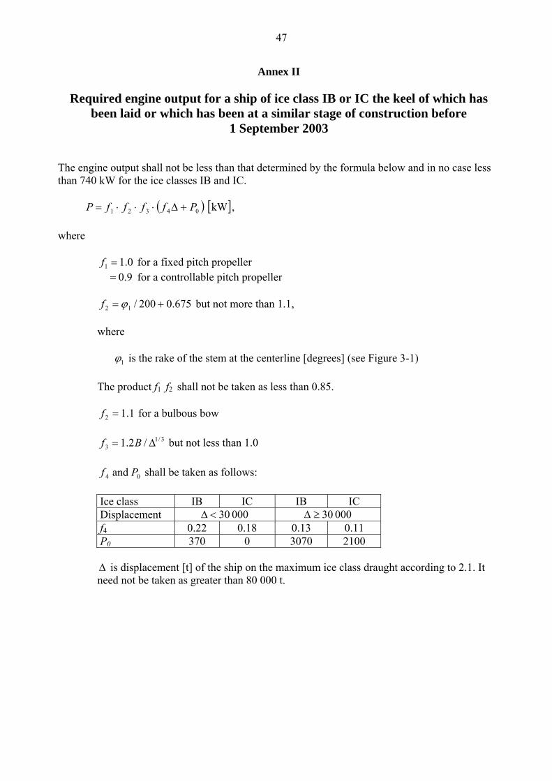
47
Annex II
Required engine output for a ship of ice class IB or IC the keel of which has
been laid or which has been at a similar stage of construction before 1 September 2003
The engine output shall not be less than that determined by the formula below and in no case less than 740 kW for the ice classes IB and IC.
( ) [ ]kW 04321 PffffP +Δ⋅⋅⋅= ,
where
0.11 =f for a fixed pitch propeller 0.9 = for a controllable pitch propeller
675.0200/12 += ϕf but not more than 1.1, where
1ϕ is the rake of the stem at the centerline [degrees] (see Figure 3-1) The product f1 f2 shall not be taken as less than 0.85.
1.12 =f for a bulbous bow
3/1
3 /2.1 Δ= Bf but not less than 1.0
04 and Pf shall be taken as follows:
Ice class IB IC IB IC Displacement 000 30<Δ 000 30≥Δ f4 0.22 0.18 0.13 0.11 P0 370 0 3070 2100
Δ is displacement [t] of the ship on the maximum ice class draught according to 2.1. It need not be taken as greater than 80 000 t.
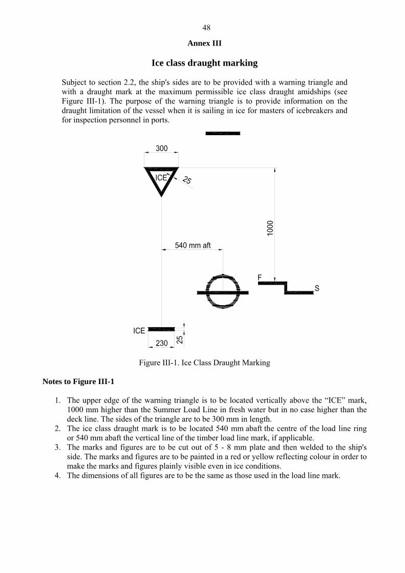
48
Annex III
Ice class draught marking
Subject to section 2.2, the ship's sides are to be provided with a warning triangle and with a draught mark at the maximum permissible ice class draught amidships (see Figure III-1). The purpose of the warning triangle is to provide information on the draught limitation of the vessel when it is sailing in ice for masters of icebreakers and for inspection personnel in ports.
Figure III-1. Ice Class Draught Marking
Notes to Figure III-1
1. The upper edge of the warning triangle is to be located vertically above the “ICE” mark, 1000 mm higher than the Summer Load Line in fresh water but in no case higher than the deck line. The sides of the triangle are to be 300 mm in length.
2. The ice class draught mark is to be located 540 mm abaft the centre of the load line ring or 540 mm abaft the vertical line of the timber load line mark, if applicable.
3. The marks and figures are to be cut out of 5 - 8 mm plate and then welded to the ship's side. The marks and figures are to be painted in a red or yellow reflecting colour in order to make the marks and figures plainly visible even in ice conditions.
4. The dimensions of all figures are to be the same as those used in the load line mark.