fire detection and life safety - national treasury · pdf file2.3.15 fire detection and alarm...
TRANSCRIPT

Standard Technology
Title: Fire Detection and Life Safety Design Standard
Unique Identifier: 240-56737448
Alternative Reference Number: N/A
Area of Applicability: Engineering
Documentation Type: Standard
Revision: 2
Total Pages: 50
Next Review Date: November 2017
Disclosure Classification: CONTROLLED DISCLOSURE
Compiled by Approved by Authorised by
………………………………….. ………………………………….. …………………………………..
Andre van den Berg
Snr C&I Engineer
Khaya Sobuwa
Plant CoE Manager Governance
Prudence Madiba
Senior Manager EC&I
Date: …………………………… Date: …………………………… Date: ……………………………
Supported by SCOT SC
…………………………………..
N. Nkosi
Low Pressure Services SC Chairman
Date: ……………………………

Fire Detection and Life Safety Design Standard
CONTROLLED DISCLOSURE When downloaded from the EDMS, this document is uncontrolled and the responsibility rests with the user to ensure it is in line
with the authorised version on the system.
Unique Identifier: 240-56737448
Revision: 2
Page: 2 of 50
CONTENTS Page
1. INTRODUCTION ...................................................................................................................................................... 5
2. SUPPORTING CLAUSES ........................................................................................................................................ 5
SCOPE .............................................................................................................................................................. 5 2.12.1.1 Purpose ..................................................................................................................................................... 5 2.1.2 Applicability................................................................................................................................................ 6 NORMATIVE/INFORMATIVE REFERENCES .................................................................................................. 6 2.22.2.1 Normative References ............................................................................................................................... 6 2.2.2 Informative References ............................................................................................................................. 7
2.2.2.1 South African National Standards ..................................................................................................... 7 2.2.2.2 National Fire Protection Association ................................................................................................. 7 2.2.2.3 Other ................................................................................................................................................. 7
DEFINITIONS .................................................................................................................................................... 7 2.32.3.1 Alarm Device ............................................................................................................................................. 7 2.3.2 Alarm Zone ................................................................................................................................................ 8 2.3.3 Analogue Addressable System ................................................................................................................. 8 2.3.4 Automatic Fire Detection and Alarm System ............................................................................................ 8 2.3.5 Bulk Materials Handling ............................................................................................................................. 8 2.3.6 Competent Person [NBR Definition] .......................................................................................................... 8 2.3.7 Computer Room ........................................................................................................................................ 8 2.3.8 Controlled Disclosure ................................................................................................................................ 8 2.3.9 Conventional System ................................................................................................................................ 8 2.3.10 Critical: Any part or area of plant/facility is seen to be critical if its loss during a fire incident has
the potential to cause the following, either immediately or within a 6-12 hour period after the incident: ...... 8 2.3.11 Critical Path ............................................................................................................................................. 9 2.3.12 Deflagration ............................................................................................................................................. 9 2.3.13 Detection Zone ........................................................................................................................................ 9 2.3.14 Equipment Room ..................................................................................................................................... 9 2.3.15 Fire Detection and Alarm System ........................................................................................................... 9 2.3.16 Fire Detection Panel ................................................................................................................................ 9 2.3.17 Fire Detector ............................................................................................................................................ 9 2.3.18 Flame ....................................................................................................................................................... 9 2.3.19 Listed ....................................................................................................................................................... 9 2.3.20 Manual Call Point .................................................................................................................................... 9 2.3.21 Risk Analysis ......................................................................................................................................... 10 2.3.22 Server Room ......................................................................................................................................... 10 2.3.23 Smoke ................................................................................................................................................... 10 2.3.24 Smoke Detector ..................................................................................................................................... 10 2.3.25 Substation.............................................................................................................................................. 10 ABBREVIATIONS ............................................................................................................................................ 10 2.4 ROLES AND RESPONSIBILITIES .................................................................................................................. 12 2.5 PROCESS FOR MONITORING ...................................................................................................................... 12 2.6 RELATED/SUPPORTING DOCUMENTS ....................................................................................................... 12 2.7
3. DESIGN APPROACH ............................................................................................................................................ 12
DEEMED TO SATISFY APPROACH .............................................................................................................. 12 3.1 RATIONAL FIRE DESIGN - CODE COMPLIANT DESIGN APPROACH....................................................... 12 3.2 RATIONAL FIRE DESIGN - FIRE ENGINEERED DESIGN APPROACH ...................................................... 13 3.3
4. AREAS AND SYSTEMS ........................................................................................................................................ 14
INTRODUCTION ............................................................................................................................................. 14 4.1 AREA AND SYSTEM MATRICES ................................................................................................................... 15 4.2
5. FIRE DETECTION SYSTEMS SPECIAL APPLICATION ..................................................................................... 21

Fire Detection and Life Safety Design Standard
CONTROLLED DISCLOSURE When downloaded from the EDMS, this document is uncontrolled and the responsibility rests with the user to ensure it is in line
with the authorised version on the system.
Unique Identifier: 240-56737448
Revision: 2
Page: 3 of 50
GENERAL POWER PLANT EQUIPMENT ...................................................................................................... 21 5.15.1.1 Coal Handling .......................................................................................................................................... 21
5.1.1.1 Bulk Materials Handling .................................................................................................................. 22 5.1.2 Turbine Areas .......................................................................................................................................... 22
5.1.2.1 Gas Turbine..................................................................................................................................... 22 5.1.2.2 Steam Turbine ................................................................................................................................. 22
5.1.3 Electrical Equipment ................................................................................................................................ 22 5.1.4 Control Rooms......................................................................................................................................... 23 5.1.5 Transformers ........................................................................................................................................... 23 5.1.6 Boiler Houses .......................................................................................................................................... 23 5.1.7 Computer, Server, Equipment Rooms & Simulator Areas ...................................................................... 23 5.1.8 Administration Building ............................................................................................................................ 24 HYDRO POWER FACILITIES ......................................................................................................................... 24 5.2 WIND TURBINE GENERATING FACILITIES ................................................................................................. 24 5.35.3.1 General .................................................................................................................................................... 24 5.3.2 Fire Detection .......................................................................................................................................... 24 5.3.3 Room Monitoring ..................................................................................................................................... 25 5.3.4 Installation Monitoring ............................................................................................................................. 25 SOLAR POWER FACILITIES.......................................................................................................................... 26 5.45.4.1 General .................................................................................................................................................... 26 5.4.2 Detection ................................................................................................................................................. 27 SLEEPING QUARTERS .................................................................................................................................. 28 5.55.5.1 General .................................................................................................................................................... 28
6. SYSTEM DESCRIPTION ....................................................................................................................................... 28
GENERAL REQUIREMENTS ......................................................................................................................... 28 6.1 CATEGORIES OF SYSTEMS ......................................................................................................................... 29 6.2 SYSTEM DESCRIPTIONS .............................................................................................................................. 29 6.3 EQUIPMENT DESCRIPTION.......................................................................................................................... 30 6.46.4.1 General .................................................................................................................................................... 30 6.4.2 Manual Call Points .................................................................................................................................. 31 6.4.3 Point Type Heat Detectors ...................................................................................................................... 31 6.4.4 Linear / Line Type Heat Detectors........................................................................................................... 31 6.4.5 Point Type Smoke Detectors ................................................................................................................... 31 6.4.6 Beam Type Smoke Detectors ................................................................................................................. 32 6.4.7 Multi Sensor Detectors ............................................................................................................................ 32 6.4.8 Flame Detectors ...................................................................................................................................... 32 6.4.9 Aspirating Systems .................................................................................................................................. 32 6.4.10 Video Based Fire Detection ................................................................................................................... 33 6.4.11 Gas Detectors........................................................................................................................................ 33 6.4.12 Mechanical Pilot Sprinkler Detection ..................................................................................................... 33 6.4.13 Sounders ............................................................................................................................................... 34 6.4.14 Visual Alarms......................................................................................................................................... 34 6.4.15 Portable Alarms ..................................................................................................................................... 35 6.4.16 Control and Indicating Equipment ......................................................................................................... 35 6.4.17 Fire Alarm Interfaces ............................................................................................................................. 35 6.4.18 Cabling, Conduits and Racking ............................................................................................................. 36 6.4.19 Alternatives ............................................................................................................................................ 36
7. FIRE DETECTION SYSTEMS SPECIFIC INSTALLATION REQUIREMENTS .................................................... 36
HAZARDOUS LOCATIONS ............................................................................................................................ 36 7.1
8. INTERFACES TO THE FIRE DETECTION SYSTEM ........................................................................................... 41
FDS INTERFACES (LOCAL) .......................................................................................................................... 41 8.1 FDS INTERFACES & NETWORKING (SITE WIDE) ...................................................................................... 42 8.28.2.1 Fire Detection Network ............................................................................................................................ 42 8.2.2 Fire Detection Network Routing Design .................................................................................................. 43

Fire Detection and Life Safety Design Standard
CONTROLLED DISCLOSURE When downloaded from the EDMS, this document is uncontrolled and the responsibility rests with the user to ensure it is in line
with the authorised version on the system.
Unique Identifier: 240-56737448
Revision: 2
Page: 4 of 50
FIRE DETECTION SYSTEM HMI ................................................................................................................... 43 8.3 HVAC INTERFACE ......................................................................................................................................... 44 8.4 CBMS INTERFACE ......................................................................................................................................... 44 8.5
9. SYSTEM PERFORMANCE .................................................................................................................................... 45
10. STANDARDISATION ........................................................................................................................................... 45
11. COMMISSIONING AND HAND-OVER, INSPECTION, TESTING, AND MAINTENANCE ................................ 46
COMMISSIONING AND HAND-OVER ......................................................................................................... 46 11.1 INSPECTION, TESTING AND MAINTENANCE ........................................................................................... 47 11.2 DOCUMENTATION ....................................................................................................................................... 47 11.3
12. AUTHORISATION ................................................................................................................................................ 48
13. REVISIONS .......................................................................................................................................................... 50
14. DEVELOPMENT TEAM ....................................................................................................................................... 50
15. ACKNOWLEDGEMENTS .................................................................................................................................... 50
TABLES
Table 1: Fire Detection System Application Matrix ..................................................................................................... 16 Table 2: Fire Detection System Types ....................................................................................................................... 29 Table 3: Fire Detection System Types ....................................................................................................................... 34 Table 4: Classification of Hazardous Areas – Flammable Dusts ............................................................................... 38 Table 5: Classification of Hazardous Areas – Flammable Vapours and Gases ......................................................... 39
FIGURES Figure 1: Schematic of a typical Photovoltaic Power Plant ........................................................................................ 26 Figure 2: Schematic of a typical Concentrated Solar Power plant using Central Receiver Technology .................... 27 Figure 3: Local Fire Detection Panel Interfaces ......................................................................................................... 42 Figure 4: FDS Site Wide Network and Interfaces ....................................................................................................... 43

CONTROLLED DISCLOSURE When downloaded from the EDMS, this document is uncontrolled and the responsibility rests with the user to ensure it is in line
with the authorised version on the system.
Fire Detection and Life Safety Design Standard
Unique Identifier: 240-56737448
Revision: 2
Page: 5 of 50
1. INTRODUCTION
This document is to be used as a Standard for implementing an automatic fire detection system (FDS) for the various areas typically found in Eskom power stations and other Eskom facilities/assets throughout South Africa.
It is intended that this Standard will provide an up-to-date, economical, suitable and uniform approach to the fire detection systems throughout Eskom.
An automatic FDS protects the building and its occupants by detecting a fire at an early stage of its development. By providing an early warning to the occupants of a building, usually through a central emergency preparedness centre, action can be taken to deal with a fire before it is allowed to develop into an uncontrollable fire. Fire detection systems used in buildings have a good record of performance and have demonstrated that they can be effective in reducing the risk to life and property damage from fire.
This Standard is primarily based on SANS 10139:2007 - Fire Detection and Alarm Systems for Buildings, which shall form the basis of all FDS designs. SANS 10139 [7] shall be applied where a Deemed to Satisfy (i.e. code prescriptive) route is to be followed. Any deviation from SANS 10139 [7] will require an alternative fire engineered solution, however this would be subject to the outcomes of a fire detection assessment.
This Standard aims to assist those involved in the specification, design, operation, maintenance and modification of fire detection systems at the various Eskom utilities.
It is critical to understand that a detailed risk assessment – in the form of a Fire Protection/Detection Assessment, guided by 240-54937439 must be undertaken to determine the specific requirements of a site. In the scheme of risk management the proverb “prevention is better than cure” is true. The minimisation of the likelihood of occurrence of an undesired event is much more cost effective than implementation of measures which will reduce the severity of the associated undesired consequences. It is a fact that it is much more cost effective to prevent a fire from occurring than to install and maintain fire detection and suppression systems, and in the end having to clean up following the occurrence of a fire and subsequent operation of protective systems.
2. SUPPORTING CLAUSES
SCOPE 2.1
The Standard is aimed at those persons responsible for the specification, design, construction, commissioning, operating, maintenance and modification of fire detection systems for Eskom Holdings.
2.1.1 Purpose
The purpose of this document is to serve as a Standard for persons responsible for the specification, design, construction, commissioning, operation, maintenance and modification of fire detection systems for Eskom Holdings.
There are many factors to consider when determining the best FDS for a particular application, such as local statutory requirements, international codes and standards, industry best practice, experience gained, and many others. This Standard sets out to pull together all of these requirements and to propose various options available to the engineers responsible for the design.
There are also many different methods, systems, technologies, equipment, etc. available to use. This Standard introduces the major components that are used in fire detection systems, as well as the types of system that are available to designers. The Standard sets out to pull together the elements associated

CONTROLLED DISCLOSURE When downloaded from the EDMS, this document is uncontrolled and the responsibility rests with the user to ensure it is in line
with the authorised version on the system.
Fire Detection and Life Safety Design Standard
Unique Identifier: 240-56737448
Revision: 2
Page: 6 of 50
with these systems so that the reader has a comprehensive understanding of what goes into putting them together.
This Standard gives specific examples of systems which can be used for typical areas at Eskom assets.
This is to ensure that high standards of reliability, availability, maintainability, safety and security are achieved, together with acceptable standards of performance. It also attempts to obtain a certain level of standardization throughout the various Eskom sites.
2.1.2 Applicability
This Standard shall apply throughout Eskom Holdings Limited Divisions.
This Standard is applicable to Technology, Generation, Peaking, Transmission and Distribution where similar equipment is utilised for power generation, transmission and distribution. It is equally applicable to Eskom commercial assets such as Eskom Megawatt Park.
This Standard is primarily directed at new installations in power stations. It may, however, be used as a Standard to retrofit, modify or extend FDS’s at existing sites. (For example: where major control system refurbishments are planned) It may also be used as a benchmark for evaluating the applicability and suitability of existing FDS’s at existing sites and therefore determining the current risks involved.
This Standard is primarily intended for use in Eskom and consequently International and South African standards and codes of practice have been referenced. The principles of system operation and maintenance, as well as the technical information about components and systems, can be applied in other Eskom facilities subject to local authority and code requirements.
NORMATIVE/INFORMATIVE REFERENCES 2.2
This Standard aims to supplement the various existing codes, standards and methods available and to give guidance on how to comply with recognized codes, standards and methods. It does not intend to overrule any of these codes, standards or methods, nor does it intend to create new requirements.
This Standard is primarily based on SANS 10139:2007 - Fire Detection and Alarm Systems for Buildings – System Design, Installation and Servicing [7], which shall form the basis of all FDS designs.
All works shall comply with all documents and standards referenced herein.
Where a standard comprises several parts all parts shall apply, where applicable.
Parties using this document shall apply the most recent edition of the documents referenced herein.
2.2.1 Normative References
The following codes and standards are considered to be indispensable to using this document. All of these documents are to be complied with in all respects, where applicable:
[1] ISO 9001 Quality Management System
[2] 240-54937439 Fire Protection / Detection Assessment
[3] 240-54937450 Fire Protection and Life Safety Design Standard
[4] 240-54937454 Inspection, Testing and Maintenance of Fire Protection Systems
[5] 240-56737654 Inspection, Testing and Maintenance of Fire Detection Systems
[6] SANS 10400-T The Application of the National Building Regulations – Fire Protection

CONTROLLED DISCLOSURE When downloaded from the EDMS, this document is uncontrolled and the responsibility rests with the user to ensure it is in line
with the authorised version on the system.
Fire Detection and Life Safety Design Standard
Unique Identifier: 240-56737448
Revision: 2
Page: 7 of 50
[7] SANS 10139 Fire Detection and Alarm Systems for Buildings – System Design, Installation and Servicing
[8] SANS 50054 Fire Detection and Fire Alarm Systems (Adopted from BS EN 54)
[9] SANS 10108 The Classification of Hazardous Locations and the Selection of Apparatus for Use in such Locations
[10] ARP 0108 Recommended Practice - Regulatory Requirements for Explosion Protected Apparatus
[11] 240-53114026 Project Engineering Change Management Procedure
[12] 240-53114002 Engineering Change Management Procedure
[13] 240-53113685 Design Review Procedure
[14] 240-57859210 Alarm System Performance of Digital Control Systems Applied in Fossil Plant
[15] 32-123 Emergency Planning
2.2.2 Informative References
The following codes and standards are considered valuable as additional sources of information:
2.2.2.1 South African National Standards
[16] SANS 10400-A The Application of the National Building Regulations – General Principles and Requirements.
[17] SANS 246 Code of Practice for Fire Protection for Electronic Equipment Installations
2.2.2.2 National Fire Protection Association
[18] NFPA 15 Standard for Spray Fixed Systems
[19] NFPA 850 Recommended Practice for Fire Protection for Electric Generating Plants and High Voltage Plants and High Voltage Direct Current Converter Stations
[20] NFPA 72 National Fire Alarm and Signaling Code
2.2.2.3 Other
[21] BFPA Code of Practice for Design, Installation, Commissioning and Maintenance of Aspirating Smoke Detector (ASD) Systems.
[22] BS 7974 Application of Fire Safety Engineering Principles to the Design of Buildings
[23] CFPA E No 22 Wind Turbine Fire Protection Guideline
[24] BS EN 50200 Method of Test for Resistance to Fire of Unprotected Small Cables for Use in Emergency Circuits
[25] EN 54-18 Fire Detection and Alarm Systems Part 18: Input / Output Devices
DEFINITIONS 2.3
2.3.1 Alarm Device
A device which can be used to warn occupants of a fire condition, either audibly or visually, such as sounders or strobes/beacons.

CONTROLLED DISCLOSURE When downloaded from the EDMS, this document is uncontrolled and the responsibility rests with the user to ensure it is in line
with the authorised version on the system.
Fire Detection and Life Safety Design Standard
Unique Identifier: 240-56737448
Revision: 2
Page: 8 of 50
2.3.2 Alarm Zone
A geographical subdivision of the protected premises, in which the fire alarm warning can be given separately, and independently, of a fire alarm warning in any other alarm zone. (This is not necessarily the same zone as the detection zone).
2.3.3 Analogue Addressable System
A system where each detecting device, alarming device and any other input or output device can be individually identified, with their own unique address, at the control and indicating equipment.
2.3.4 Automatic Fire Detection and Alarm System
A system that is able to automatically detect a fire at an early stage and automatically initiate the appropriate alarm response.
2.3.5 Bulk Materials Handling
Refers to the systems used to transport materials from one point to another and includes all conveyors and transfer facilities. The materials transported include coal, ash, limestone and gypsum.
2.3.6 Competent Person [NBR Definition]
Means a person who is qualified by virtue of his education, training, experience and contextual knowledge to make a determination regarding the performance of a building or part thereof in relation to a functional regulation or to undertake such duties as may be assigned to him in terms of these regulations.
2.3.7 Computer Room
A room housing computer equipment used to monitor and administer the equipment housed in the Equipment Room. Usually unmanned.
2.3.8 Controlled Disclosure
Controlled disclosure to external parties (either enforced by law, or discretionary)
2.3.9 Conventional System
A system where devices are not assigned individual addresses and are not distinguishable from each other. Devices are looped, and activation of any device on a loop produces an output associated with the loop at the Control and Indicating Equipment (CIE).
2.3.10 Critical: Any part or area of plant/facility is seen to be critical if its loss during a fire incident has the potential to cause the following, either immediately or within a 6-12 hour period after the incident:
A multiple-unit load loss or trip;
Loss of transmission or distribution capability;
Permanent loss of production or products; or
Danger to fire-fighting personnel involved in fighting the fire

CONTROLLED DISCLOSURE When downloaded from the EDMS, this document is uncontrolled and the responsibility rests with the user to ensure it is in line
with the authorised version on the system.
Fire Detection and Life Safety Design Standard
Unique Identifier: 240-56737448
Revision: 2
Page: 9 of 50
2.3.11 Critical Path
The physical network path along which a signal indicating the detection of fire must traverse to alert fire responders.
2.3.12 Deflagration
Deflagration is a term describing subsonic combustion propagating through heat transfer; hot burning material heats the next layer of cold material and ignites it.
2.3.13 Detection Zone
A subdivision of the protected premises such that the occurrence of a fire within it will be indicated by a fire alarm system separately from an indication of a fire in any other subdivision. (This is not necessarily the same zone as the alarm zone)
2.3.14 Equipment Room
A room housing cubicles of electronic control and instrumentation equipment. Usually unmanned.
2.3.15 Fire Detection and Alarm System
The term fire detection and alarm systems, in the context of this standard, includes systems that range from those comprising only one or two manual call points and sounders to complex networked systems that incorporate a large number of automatic fire detectors, manual call points and sounders, connected to numerous inter-communicating control and indicating panels.
2.3.16 Fire Detection Panel
A permanent panel used for the termination, controlling, powering, operating, monitoring, indicating, testing, programming, etc. of different fire detectors, alarms and other input / output units.
2.3.17 Fire Detector
A device which can detect the presence of a fire by any means, such as smoke, heat, combustion gases, radiation, light, etc. (Not necessarily a smoke detector)
2.3.18 Flame
A self-sustained chemical process that produces heat and light. It requires the oxidation of a fuel by an oxidant, usually oxygen.
2.3.19 Listed
Equipment, materials, or services in a listed publication by an organisation that is acceptable to the Eskom and the organisation must be concerned with evaluation of products or services, that maintains periodic inspection of production of listed equipment or materials or periodic evaluation of services, and whose listing state that either the equipment, materials or periodic evaluation of service meets appropriate designated standards or has been tested and found suitable for a specific purpose.
2.3.20 Manual Call Point
A device which is manually activated to indicate that there is a fire and initiates an alarm.

CONTROLLED DISCLOSURE When downloaded from the EDMS, this document is uncontrolled and the responsibility rests with the user to ensure it is in line
with the authorised version on the system.
Fire Detection and Life Safety Design Standard
Unique Identifier: 240-56737448
Revision: 2
Page: 10 of 50
2.3.21 Risk Analysis
A process to characterise the likelihood, vulnerability, and magnitude of incidents associated with natural, technological, and manmade disasters and other emergencies that address scenarios of concern, their probability, and their potential consequences.
2.3.22 Server Room
A room housing racks of computer equipment either for the Control and Instrumentation DCS system or the IT department LAN system.
2.3.23 Smoke
Particulate and aerosol products of combustion generated by a fire, whether this be of smouldering or open flame type.
2.3.24 Smoke Detector
A device which can detect a fire by the identification of the presence of smoke particles in the air. (One type of fire detector).
2.3.25 Substation
A room or open area housing low voltage, medium voltage or high voltage equipment and switchgear.
ABBREVIATIONS 2.4
Abbreviation Description
AFNORM Association Francaise de Normalisation
ARP A Recommended Practice
ASD Aspirating Smoke Detector
ASIB The Automatic Sprinkler Inspection Bureau (Pty) Ltd
BFPSA British Fire Protection Systems Association
BMS Building Management System
BOP Balance of Plant
BS British Standard
CBMS Consolidated Building Management System
CCTV Closed Circuit Television
CSA Canadian Standards Association
CSP Concentrated Solar Power
dBA Decibel (A-Weighted)
DCS Distributed Control System
DTS Deemed-to-Satisfy
ECSA Engineering Council of South Africa

CONTROLLED DISCLOSURE When downloaded from the EDMS, this document is uncontrolled and the responsibility rests with the user to ensure it is in line
with the authorised version on the system.
Fire Detection and Life Safety Design Standard
Unique Identifier: 240-56737448
Revision: 2
Page: 11 of 50
Abbreviation Description
EN European Norm
FAT Factory acceptance test
FDIA Fire Detection Installers Association
FDS Fire Detection & Alarm System
FM Factory Mutual (Global)
HMI Human Machine Interface
HSSD High Sensitivity Smoke Detector
HTF Heat Transfer Fluid
HVAC Heating Ventilation and Air Conditioning
I/O Input / Output
IR Infra-Red
IT Information Technology
ISO International Standards Organisation
KPI Key Performance Indicator
LAN Local Area Network
LPC Loss Prevention Council
LPCB Loss Prevention Certification Board
MCP Manual Call Point
NBR National Building Regulation
NFPA National Fire Protection Association
OEM Original Equipment Manufacturer
PV Photo Voltaic
SAA Standards Association Australia
SABS South African Bureau of Standards
SANS South African National Standards
SAT Site Acceptance Test
SAQCC South African Qualifications and Certification Committee
SIT Site Integration Tests
UL Underwriters Laboratory
UPS Uninterrupted Power Supply
UV Ultra Violet
VBFD Video Based Fire Detection
VDSS Vendor Document Submittal Schedule

CONTROLLED DISCLOSURE When downloaded from the EDMS, this document is uncontrolled and the responsibility rests with the user to ensure it is in line
with the authorised version on the system.
Fire Detection and Life Safety Design Standard
Unique Identifier: 240-56737448
Revision: 2
Page: 12 of 50
ROLES AND RESPONSIBILITIES 2.5
Detection measures detailed in this document are to be implemented by a competent person only. The competent person is to ensure that they also fully comply with the Eskom Project Engineering Change Procedure [11], Eskom Design Review Procedure [13].
PROCESS FOR MONITORING 2.6
Regular Fire audits to be conducted by each site.
RELATED/SUPPORTING DOCUMENTS 2.7
[26] GGS 0315 Drawings
[27] GGS 0350 Generation Fire Risk Management
[28] 240-36536505 Hazardous Locations Management
[29] 36-681 Plant Safety Regulations (GGR 0992)
[30] ESKMAAD1 Storage and Handling of Flammable and Combustible Liquids
[31] EST 32-107 Eskom Fire Fighting Training Programme
[32] EST 32-108 Fire Fighting Organisation
[33] EST 32-124 Eskom Fire Risk Management
3. DESIGN APPROACH
The user of this Standard has two options to approach the design of the fire detection systems.
a. Deemed to Satisfy – Follow the requirements in the South African National Standards (SANS).
b. Rational Fire Design
i. Rational Alternative Code Compliant Design - Follow the requirements in codes and standards other than the South African Nation Standards (SANS).
ii. Rational Fire Engineered Design - Use a risk based approach and follow acceptable decision making process using fire engineering principles. This will particularly apply to special risk applications.
DEEMED TO SATISFY APPROACH 3.1
SANS 10400 sets out the different possible ways of demonstrating compliance with functional regulations, including a range of prescriptive provisions that are “deemed to satisfy” the requirements of the National Building Regulations. If a design is complaint to SANS10400 and any of the normative SANS documents referenced within then the design can be classified as deemed to satisfy The use of any document other than a SANS document would require justification as the design would then be deemed a “rational fire design”.
RATIONAL FIRE DESIGN - CODE COMPLIANT DESIGN APPROACH 3.2
Where the South African National Standards does not address a specific fire risk or area of plant a Rational Fire Design will need to be performed and this will usually require looking at codes of practise other than the South African National Standards. For example recommended fire protection measures

CONTROLLED DISCLOSURE When downloaded from the EDMS, this document is uncontrolled and the responsibility rests with the user to ensure it is in line
with the authorised version on the system.
Fire Detection and Life Safety Design Standard
Unique Identifier: 240-56737448
Revision: 2
Page: 13 of 50
for power stations can be found in application-specific fire protection design Standards such as those produced by the NFPA.
These solutions have been found to be adequate and are considered best industry practice for their particular environments, Compliance to these codes is acceptable for providing a safe, workable solution to some of the buildings, equipment, areas and sites at Eskom Holdings.
Even though there are many documents which prescribe an adequate code compliant approach, there will always be factors which cannot be accounted for and will require additional engineering. Such factors are:
a. Suitability of the fire protection and fire detection components;
b. Nature of the site, buildings and equipment;
c. Environmental and atmospheric factors specific to the area, such as temperatures, humidity, wind, dust, smog, etc.
d. Operations in the areas;
e. The level of monitoring and control required for the site as a whole;
f. The personnel occupying the buildings as well as using the FDS system;
g. Areas not covered in the documents;
An alternative to complying with the Rational Fire Design – Alternative Code Compliant Design approach may be taken by implementing a Rational Fire Design – Fire Engineered Design approach
RATIONAL FIRE DESIGN - FIRE ENGINEERED DESIGN APPROACH 3.3
A fire engineered solution is now recognised in South Africa as an effective way of meeting fire safety objectives. Although specialist fire safety engineers develop and deliver fire engineering design solutions, designers from other disciplines (such as fire protection, HVAC, emergency preparedness, access control, etc.) will often be asked to provide a major input into the way in which the fire safety strategy is developed. Fire safety engineering offers a flexible alternative to code prescriptive approaches, especially when designing for unusual or difficult buildings. A fire safety engineering approach can provide an alternative approach to fire safety, a fact that is recognised in SANS 10400-T [6] fire safety code and standards.
Fire engineered solutions may be the only viable way to achieve a satisfactory standard of fire safety in large and complex areas of the power stations, and often it is the most effective way of dealing with changes to existing buildings. It can be usefully adopted for certain elements of a building design where the remainder of the building has been designed according to the prescriptive codes. This alternative approach is often the most effective and sometimes the only way to achieve the appropriate level of safety in meeting the latest code requirements for existing buildings.
The use of fire engineering solutions allows beneficial effects to be recognised. For example, the provision of automatic fire suppression can reduce the design fire size, which may in turn lead to a more economic smoke control system design or reduced structural fire protection.
The concept of fire safety engineering provides a framework that enables designers to demonstrate that the functional requirements of legislation are met, or bettered, even though the design solutions adopted fall outside the recommendations of prescriptive codes and guidance.
Fire engineering solutions also allows functional objectives beyond life safety to be addressed, for example, property protection, business continuity, environmental and sustainability objectives.
To achieve this objective, the first step is to understand the functional requirements underlying the prescribed standards. Small departures can then be accepted without a full fire engineering analysis. For

CONTROLLED DISCLOSURE When downloaded from the EDMS, this document is uncontrolled and the responsibility rests with the user to ensure it is in line
with the authorised version on the system.
Fire Detection and Life Safety Design Standard
Unique Identifier: 240-56737448
Revision: 2
Page: 14 of 50
example, adding fully automatic fire detection may allow an increase in escape travel distance or an increase in compartment size due to the early alarm and earlier contact with the Fire Service.
However, where there is a greater difference between the building design and the guidance offered by codes, the best way is to follow analytical techniques that demonstrate the control of fire growth, the control of smoke spread and the movement of people which may be required to prove the overall fire safety strategy. The first step in preparing such an analysis is to define the building geometry, functional planning, construction materials and the general use of the building.
While many aspects of the analysis may be quantified, others will require subjective judgment and will be subject to discussion with the building control and fire authorities. They may include, for example, the consequences of fire (which will be subject to the standard of construction and maintenance) or people movement (subject to a motivation or mobilisation time, which may be improved with training or stewarding).
The person who uses this document for the purpose of designing the Fire Protection systems must be a competent person as specified in the National Building Regulation [NBR], section A19 and AZ4.
Eskom Holdings requires that the person responsible shall have at least the following qualifications:
Bachelor Degree in Engineering or higher
Registered Professional Engineer with ECSA
At least 4 years of experience in fire engineering
4. AREAS AND SYSTEMS
INTRODUCTION 4.1
This section aims to address the most appropriate systems and technologies to use within each specific area of the Eskom assets, which will provide the best detection.
The proposed systems are combinations of codes, standards, industry best practice and experience.
In most cases, this section provides more than one option for each area, as there will very rarely be only one option which will always be the best choice. It shall be the responsibility of the user of this document to decide which system, if any, is to be used.
The inappropriate selection of fire detection and alarm equipment in a power station environment may contribute to unnecessary false alarms, slow detection times of fires, high installation and maintenance costs, increased outages and potentially unwanted ignition sources within hazardous areas representing a fire and explosion hazard. This could possibly be the cause of subsequent risk to life safety, asset loss and production down time.
A balance is also required between simple and sophisticated fire detection technology, which must be appropriate to the operating environment.
Even though this Standard basically allows for a DTS approach, there will always be factors which cannot be accounted for and will require additional engineering. Such factors are:
Suitability of the FDS components;
Nature of the site, buildings and equipment;
Environmental and atmospheric factors specific to the area, such as temperatures, humidity, wind, dust and smog;
Operations in the areas;
The level of monitoring and control required for the site as a whole and the integration into a CBMS;

CONTROLLED DISCLOSURE When downloaded from the EDMS, this document is uncontrolled and the responsibility rests with the user to ensure it is in line
with the authorised version on the system.
Fire Detection and Life Safety Design Standard
Unique Identifier: 240-56737448
Revision: 2
Page: 15 of 50
The personnel occupying the buildings as well as using the FDS;
Areas not covered in the Standards;
Therefore, a risk based approach is required in undertaking the selection of the fire detection and alarm system technology in Eskom power station facilities.
AREA AND SYSTEM MATRICES 4.2
The following tables show the areas typically found in Eskom power stations and propose which FDS would be applicable to such areas.

CONTROLLED DISCLOSURE When downloaded from the EDMS, this document is uncontrolled and the responsibility rests with the user to ensure it is in line
with the authorised version on the system.
Fire Detection and Life Safety Design Standard
Unique Identifier: 240-56737448
Revision: 2
Page: 16 of 50
Table 1: Fire Detection System Application Matrix
Fire Detection Systems M
anu
al c
all p
oin
ts
Po
int
typ
e p
rob
e h
eat
de
tect
ors
c/w
he
at c
olle
cto
r
Lin
ear
he
at D
ete
cto
rs (
Fib
re-L
ase
r)
Po
int
typ
e s
mo
ke d
ete
cto
rs
Be
am t
ype
sm
oke
de
tect
ors
Mu
lti s
en
sor
de
tect
ors
Flam
e d
ete
cto
rs (
Trip
le IR
)
Asp
irat
ing
smo
ke d
ete
ctio
n
Vid
eo
Bas
ed
Fir
e D
ete
ctio
n
Sou
nd
ers
Vis
ual
ala
rms
Po
rtab
le a
larm
s
Co
ntr
ol a
nd
ind
icat
ing
eq
uip
me
nt
Fire
ala
rm in
terf
ace
s
Ad
dre
ssab
le In
pu
t /
Ou
tpu
t M
od
ule
s
Fie
ld d
evi
ce c
ablin
g
Ne
two
rk c
ablin
g
Inte
rfac
es
to o
ther
sys
tem
s
Inst
alla
tio
n a
nd
te
st
Co
mm
issi
on
ing
and
han
do
ver
Do
cum
en
tati
on
Logb
oo
k
Location System Types Comments
Outdoor Transformers X
X X
X
X X Sprinkler activated deluge system or spray system
Indoor Transformers
X
X
X X
X
X X
Early smoke / flame detection by VBFD plus sprinkler activated deluge / spray system
Boiler Room
X
X X
X
X X X
Early smoke / flame detection by VBFD plus backup heat detection
Turbine Building
X
X X
X
X X X
Early smoke / flame detection by VBFD plus backup heat detection
Combustion Turbine Compartment X
X X X
X X X Early flame detection plus backup heat detection
Turbine Generator X X
X X X Early flame detection plus backup heat detection
Control Room
X X X
X X X
Smoke and carbon monoxide detection by multi criteria/sensor point detectors
Cable Spreading Room X X
X
X X X Early smoke / flame detection by VBFD
Switchgear Room
X X X X
X X
X
X
X X
Early smoke detection by aspirating system with gaseous suppression interface
Relay Rooms (Switchgear)
X X X X
X X
X
X
X X
Early smoke detection by aspirating system with gaseous suppression interface
Battery Rooms
X X X
X X
X
X
X X
Early smoke detection by aspirating system with gaseous suppression interface
Substations and Switch Yard X
X X
X
X X Sprinkler activated deluge system
Auxiliary Equipment and Other Rooms
Emergency Generator X X X
X X
X
X X Sprinkler activated deluge system

CONTROLLED DISCLOSURE When downloaded from the EDMS, this document is uncontrolled and the responsibility rests with the user to ensure it is in line
with the authorised version on the system.
Fire Detection and Life Safety Design Standard
Unique Identifier: 240-56737448
Revision: 2
Page: 17 of 50
Fire Detection Systems
Man
ual
cal
l po
ints
Po
int
typ
e p
rob
e h
eat
de
tect
ors
c/w
he
at c
olle
cto
r
Lin
ear
he
at D
ete
cto
rs (
Fib
re-L
ase
r)
Po
int
typ
e s
mo
ke d
ete
cto
rs
Be
am t
ype
sm
oke
de
tect
ors
Mu
lti s
en
sor
de
tect
ors
Flam
e d
ete
cto
rs (
Trip
le IR
)
Asp
irat
ing
smo
ke d
ete
ctio
n
Vid
eo
Bas
ed
Fir
e D
ete
ctio
n
Sou
nd
ers
Vis
ual
ala
rms
Po
rtab
le a
larm
s
Co
ntr
ol a
nd
ind
icat
ing
eq
uip
me
nt
Fire
ala
rm in
terf
ace
s
Ad
dre
ssab
le In
pu
t /
Ou
tpu
t M
od
ule
s
Fie
ld d
evi
ce c
ablin
g
Ne
two
rk c
ablin
g
Inte
rfac
es
to o
ther
sys
tem
s
Inst
alla
tio
n a
nd
te
st
Co
mm
issi
on
ing
and
han
do
ver
Do
cum
en
tati
on
Logb
oo
k
Location System Types Comments
Storage Room/ Offices/ Shops
X X X
X X X
Smoke and carbon monoxide detection by multi criteria/sensor point detectors
Warehouses
X X X
X X X
Smoke and carbon monoxide detection by multi criteria/sensor point detectors
Fire Pump Rooms
X
X X X X
X X X
Smoke and carbon monoxide detection by multi criteria/sensor point detectors
Cooling Towers X
X X
X
X X Sprinkler activated deluge system
Aux Boiler Room
X
X X
X
X X X
Early smoke / flame detection by VBFD plus backup heat detection
Unattended Facilities X
X X
X
X X Sprinkler system
Hydrogen Generation and Storage Plants
X X X X
X
X X X X
Video detection is best applied here, specially at open spaces but need specific design considerations. Rather detect H2 leaks before ignition ocures. Also keep in mind explosion proof/intrinsic installation.
Electrical equipment control enclosures
Computer, Server, Simulator & Equipment Rooms
X X X X
X X
X
X
X X
Early smoke detection by aspirating system with gaseous suppression interface
Switchgear
X X X
X X
X
X
X X
Early smoke detection by aspirating system with gaseous suppression interface
Batteries
X X X
X X
X
X
X X
Early smoke detection by aspirating system with gaseous suppression interface
Relay + Indication Gauge
X X X
X X
X
X
X X
Early smoke detection by aspirating system with gaseous suppression interface
Aux Electrical Equipment (Static X X X
X X
X
X
X X Early smoke detection by aspirating system with

CONTROLLED DISCLOSURE When downloaded from the EDMS, this document is uncontrolled and the responsibility rests with the user to ensure it is in line
with the authorised version on the system.
Fire Detection and Life Safety Design Standard
Unique Identifier: 240-56737448
Revision: 2
Page: 18 of 50
Fire Detection Systems
Man
ual
cal
l po
ints
Po
int
typ
e p
rob
e h
eat
de
tect
ors
c/w
he
at c
olle
cto
r
Lin
ear
he
at D
ete
cto
rs (
Fib
re-L
ase
r)
Po
int
typ
e s
mo
ke d
ete
cto
rs
Be
am t
ype
sm
oke
de
tect
ors
Mu
lti s
en
sor
de
tect
ors
Flam
e d
ete
cto
rs (
Trip
le IR
)
Asp
irat
ing
smo
ke d
ete
ctio
n
Vid
eo
Bas
ed
Fir
e D
ete
ctio
n
Sou
nd
ers
Vis
ual
ala
rms
Po
rtab
le a
larm
s
Co
ntr
ol a
nd
ind
icat
ing
eq
uip
me
nt
Fire
ala
rm in
terf
ace
s
Ad
dre
ssab
le In
pu
t /
Ou
tpu
t M
od
ule
s
Fie
ld d
evi
ce c
ablin
g
Ne
two
rk c
ablin
g
Inte
rfac
es
to o
ther
sys
tem
s
Inst
alla
tio
n a
nd
te
st
Co
mm
issi
on
ing
and
han
do
ver
Do
cum
en
tati
on
Logb
oo
k
Location System Types Comments
Exciting Equipment) gaseous suppression interface
Current Transformer
X X X
X X
X
X
X X
Early smoke detection by aspirating system with gaseous suppression interface
Potential Transformer
X X X
X X
X
X
X X
Early smoke detection by aspirating system with gaseous suppression interface
Grounding Transformer
X X X
X X
X
X
X X
Early smoke detection by aspirating system with gaseous suppression interface
Elevator Motor Rooms
X X
X
X X
Possibly interface with elevator controls to dock the elevator to a safe floor.
Other Electrical
X X X
X X
X
X
X X
Early smoke detection by aspirating system with gaseous suppression interface
Control Enclosures
Tipping/ Receiving Building X X
X
X X
X
X X Early smoke / flame detection by VBFD
Municipal Solid Waste Pit/ Burn Fuel Area/ Charging Floor/ Grapple Lay Down
X X
X
X X
X
X X
Early smoke / flame detection by VBFD
Refuse Derived Fuels (RFD) Storage X X
X
X X
X
X X Early smoke / flame detection by VBFD
Bio Mass Fuel Stores X X
X
X X
X
X X Early smoke / flame detection by VBFD
Rubber Tyre Stores X X
X
X X
X
X X Early smoke / flame detection by VBFD
(Initial Receiving + Storage for All Areas Listed)
X X
X
X X
X
X X
Early smoke / flame detection by VBFD
Oil Storage Rooms and pumping facilities
X X X X
X
X X
X
X X
Concentrate on detecting spills/leaks before ignition.
Hydro
Hydraulic Control Systems X X X
X X
X
X X Sprinkler activated deluge system

CONTROLLED DISCLOSURE When downloaded from the EDMS, this document is uncontrolled and the responsibility rests with the user to ensure it is in line
with the authorised version on the system.
Fire Detection and Life Safety Design Standard
Unique Identifier: 240-56737448
Revision: 2
Page: 19 of 50
Fire Detection Systems
Man
ual
cal
l po
ints
Po
int
typ
e p
rob
e h
eat
de
tect
ors
c/w
he
at c
olle
cto
r
Lin
ear
he
at D
ete
cto
rs (
Fib
re-L
ase
r)
Po
int
typ
e s
mo
ke d
ete
cto
rs
Be
am t
ype
sm
oke
de
tect
ors
Mu
lti s
en
sor
de
tect
ors
Flam
e d
ete
cto
rs (
Trip
le IR
)
Asp
irat
ing
smo
ke d
ete
ctio
n
Vid
eo
Bas
ed
Fir
e D
ete
ctio
n
Sou
nd
ers
Vis
ual
ala
rms
Po
rtab
le a
larm
s
Co
ntr
ol a
nd
ind
icat
ing
eq
uip
me
nt
Fire
ala
rm in
terf
ace
s
Ad
dre
ssab
le In
pu
t /
Ou
tpu
t M
od
ule
s
Fie
ld d
evi
ce c
ablin
g
Ne
two
rk c
ablin
g
Inte
rfac
es
to o
ther
sys
tem
s
Inst
alla
tio
n a
nd
te
st
Co
mm
issi
on
ing
and
han
do
ver
Do
cum
en
tati
on
Logb
oo
k
Location System Types Comments
Generator Pit + Windings
X X X
X X
X
X X
Gaseous fire suppression is the preferred choice over water spray in this area.
Sprinkler activated deluge system
Cable Concentration
X X X
X X
X
X
X X
Early smoke detection by aspirating system with gaseous suppression interface
Air Compressors Room X X X
X X
X
X X Sprinkler activated deluge system
Wind
Nacelle with transformer, including hub and raised floors
X X
Early smoke detection by aspirating system with gaseous suppression/water mist interface
Central electric power substation, switch cabinet rooms
X
X
X X
X X X
Early smoke detection by aspirating system with gaseous suppression interface
Tower base/platform with available installations, if applicable
X X X
Early smoke detection by aspirating system
Switchgear cabinets
X X X X
Early smoke detection by aspirating system with gaseous suppression interface
Hydraulic systems
X X X
Early smoke detection by aspirating system with deluge water spray/water-foam interface
Transformer
X X
Early smoke detection by aspirating system with deluge water spray/water-foam interface
Solar
Concentrated Solar Power (CSP) X
X X
X X
X
X X X X Early smoke detection by aspirating system
Sleeping Quarters
Bedroom
X X X X
Heat detection only if smoking rooms where smoke detectors may cause false alarms. Eskom premises are a smoke free area.

CONTROLLED DISCLOSURE When downloaded from the EDMS, this document is uncontrolled and the responsibility rests with the user to ensure it is in line
with the authorised version on the system.
Fire Detection and Life Safety Design Standard
Unique Identifier: 240-56737448
Revision: 2
Page: 20 of 50
Fire Detection Systems
Man
ual
cal
l po
ints
Po
int
typ
e p
rob
e h
eat
de
tect
ors
c/w
he
at c
olle
cto
r
Lin
ear
he
at D
ete
cto
rs (
Fib
re-L
ase
r)
Po
int
typ
e s
mo
ke d
ete
cto
rs
Be
am t
ype
sm
oke
de
tect
ors
Mu
lti s
en
sor
de
tect
ors
Flam
e d
ete
cto
rs (
Trip
le IR
)
Asp
irat
ing
smo
ke d
ete
ctio
n
Vid
eo
Bas
ed
Fir
e D
ete
ctio
n
Sou
nd
ers
Vis
ual
ala
rms
Po
rtab
le a
larm
s
Co
ntr
ol a
nd
ind
icat
ing
eq
uip
me
nt
Fire
ala
rm in
terf
ace
s
Ad
dre
ssab
le In
pu
t /
Ou
tpu
t M
od
ule
s
Fie
ld d
evi
ce c
ablin
g
Ne
two
rk c
ablin
g
Inte
rfac
es
to o
ther
sys
tem
s
Inst
alla
tio
n a
nd
te
st
Co
mm
issi
on
ing
and
han
do
ver
Do
cum
en
tati
on
Logb
oo
k
Location System Types Comments
Sounders in area where all occupants will be awakened by the sound if sleeping
Kitchen Area
X X
Heat detection because smoke from food cooking will result in false alarms
Lounge X X Only if isolated from bedrooms and kitchen
This document is not prescriptive on where the fire alarms are routed to because the document is not only applicable to power stations. Sometimes the 1st responders are sitting at the EOD, sometimes at security and sometimes at the fire station, main gate, reception etc. depending on which area of the facility is permanently (24/7) manned. Avoid having the DCS as the 1st responder station as units on outage do not always have an operator that will respond to alarms and the DCS might also be out for firmware updates itself.

CONTROLLED DISCLOSURE When downloaded from the EDMS, this document is uncontrolled and the responsibility rests with the user to ensure it is in line
with the authorised version on the system.
Fire Detection and Life Safety Design Standard
Unique Identifier: 240-56737448
Revision: 2
Page: 21 of 50
5. FIRE DETECTION SYSTEMS SPECIAL APPLICATION
This sections aims to discuss the fire detection required for special applications in specific areas found in coal, hydro, wind and solar power stations.
GENERAL POWER PLANT EQUIPMENT 5.1
Power generating plants are comprised of many different areas, each with distinct equipment that has unique hazards. Implementing a comprehensive fire protection and detection system that includes alarm, detection and suppression requires thorough understanding of the intricacies of power generating plants according to NFPA standards.
5.1.1 Coal Handling
The main areas classified at risk of fire and/or deflagration includes coal stockpiles, conveyors, pulverisers, feeders, crushers, dust collectors and silos/bunkers. Deflagration occurs as a result of the coal dust that is present in the air, and which typically settles over the interior of the power plant. As the particle size and moisture content decreases and the ambient temperature increases, there is less thermal energy required for a slow burning fire or explosion.
Typical sources of ignition in a coal-fired power plant are:
Rotating machinery parts (including conveyor belt rollers) that create friction.
Failed bearings
Sparking and static electrical charge.
Electrical equipment and switchgear overheating.
Cables and wire overheating.
Lubrication and hydraulic oils reaching their flash point
Spontaneous combustion in coal stockpiles
It is essential to protect plants from the volatile fires that are common in coal handling areas with suitable fire detection devices. Several different detectors are needed throughout the facility, depending on the location. Silos, bunkers, and dust collectors are at a high risk for explosions due to the congregation of dust. Carbon monoxide monitors, infrared scanning, temperature scanning, or linear heat detectors are adequate detection options. Linear heat detectors can detect heat along a length of space, instead of a singular spot. This works extremely well along conveyor belts, which are a major fire hazard because they easily create heat through movement or from idler or roller bearing failure.

CONTROLLED DISCLOSURE When downloaded from the EDMS, this document is uncontrolled and the responsibility rests with the user to ensure it is in line
with the authorised version on the system.
Fire Detection and Life Safety Design Standard
Unique Identifier: 240-56737448
Revision: 2
Page: 22 of 50
5.1.1.1 Bulk Materials Handling
Automatic Fixed Fire Protection Required
Manual Fire Protection (Hydrants & Hose Reels) Required
Electronic Fire Detection Required
Conveyors and transfer houses critical to power generation (irrespective of the product)
YES YES NO
All other conveyors and transfer houses (irrespective of the product)
NO YES YES
Note: see definition of “Critical” in definition section of this document.
All conveyors, irrespective of the product that for some reason e.g. logistics cannot be equipped with automatic fixed fire protection or manual fire protection should be considered to be equipped with fire detection.
5.1.2 Turbine Areas
5.1.2.1 Gas Turbine
The gas turbine consists of a vast array of piping and equipment in and under turbine areas requiring fire detection. Fuel supply in the vicinity of the burner and the lubricant circulation system including the turbine bearing in the exhaust channel present the main fire risks, given that the fuel or lubricant can ignite easily on hot surfaces. High thermal loads present in this area create an atmosphere in which fires can spread quickly aggravating the situation.
Gas turbine fire protection begins with optimal fire detection. In this area, the rapid development of open flames and heat must be considered. Flame and heat detectors developed for industrial use will be suitable.
5.1.2.2 Steam Turbine
Whether hydraulically controlled valves, turbines or generator bearings, oil supply pumps, turbine conditioning rooms or oil tank and pipe rooms, all of these sections are part of a steam turbine area.
The fire hazard emanates from flammable liquids that spread over hot surfaces due to leaks in the lubrication or control oil system. Fire protection for steam turbines should focus on protecting the equipment in the various sections.
5.1.3 Electrical Equipment
Whether for power supply or data transmission, countless cables are required for the operation and supply of a power plant. In order to provide adequate protection, in addition to for aesthetic reasons, cables are distributed via cable channels and organised in cable rooms and galleries.
The main reason for fires in such spaces is overheating with subsequent short circuits, which usually occur as a result of excess load. The risk of fire spreading at a very high speed, favoured by the draft air and the numerous cables, must be taken into account. Fire which spreads through wind and often inaccessible cable ducts can quickly cause interruptions to the operation of the power plant.

CONTROLLED DISCLOSURE When downloaded from the EDMS, this document is uncontrolled and the responsibility rests with the user to ensure it is in line
with the authorised version on the system.
Fire Detection and Life Safety Design Standard
Unique Identifier: 240-56737448
Revision: 2
Page: 23 of 50
In areas where cables are installed, fire detection systems with optical smoke detectors are to be used. Early fire detection, active smoke aspirating system should be provided to give sufficient warning and help detect fires earlier.
5.1.4 Control Rooms
Control rooms and systems are extremely sensitive and highly valuable facilities. They serve to control the elementary process in a power plant making them indispensable. In these locations fire mainly occur as a result of short circuits caused by cable or electric/ electronic components.
A fire detection system with point type smoke detectors or smoke aspirating system will ensure reliable fire detection at the earliest possible stage. Ensure covering false floors and ceiling voides as well.
5.1.5 Transformers
Transformers make sure that electricity is ready for network distribution. They function as links between the turbine, the turbine generators and the network. They consist typically of the transformer housing with a cooler, expansion deposits and oil-filled insulators.
The main fire hazard is caused by faults such as short circuits within transformers. This creates a risk of overheating and conditions in which oil can quickly ignite. Older versions of transformers are particularly susceptible to such faults.
Usually as soon as overheating is detected, the transformer is automatically deactivated in order to prevent a fire from breaking out. The basis of the fire detection is the Buchholz relay. The buchholdz relay is associated with the development of gasses in the transformer The buchholds relay is a hydraulic device installed in the pipeline between the transformer tank and the separate oil conservator. An internal fault can lead to rapid internal tank pressure rise that cases the PRV to lift or in extreme cases the tank to rupture and the result can be an intense fire. A stand alone fire system with pilot sprinklers or flame detectors together with a fully-automatic or semi-automatic deluge system is expected to successfully meet the protection aims of “control” and “suppression” in this area.
5.1.6 Boiler Houses
From the perspective of fire protection, boiler houses in power plants are usually sub-divided into two zones. On the one hand, there is the area where the technical equipment is located, such as feed water, pumps or electrical control systems; on the other, there is the location of the boiler as such where steam is generated. This area is practically devoid of fire hazards.
In areas where electric monitoring and control equipment is located, overheating may cause short circuits and smouldering fires. Leaks in oil supply system may occur on high pressure, medium pressure or low pressure pumps of the boiler feed water and condensate system.
Automatic fire detectors serve to reliably detect initial fires in areas where technical equipment is located. In addition, visible manual call points are proposed to be installed for manual activation in an event of a fire.
5.1.7 Computer, Server, Equipment Rooms & Simulator Areas
IT areas, equipped with computers and servers which monitor and control all essential processes are especially at risk if there is a fire. Faulty or overloaded electronic components can easily cause a smouldering fire or open flame fire. For computer, server and equipment rooms together with ideal fire extinguishing system (such as an inert gaseous fire suppression system), it is recommended that reliable fire detection is provided at the earliest

CONTROLLED DISCLOSURE When downloaded from the EDMS, this document is uncontrolled and the responsibility rests with the user to ensure it is in line
with the authorised version on the system.
Fire Detection and Life Safety Design Standard
Unique Identifier: 240-56737448
Revision: 2
Page: 24 of 50
stage by means of a fire detection system with point smoke detectors or smoke aspirating system. Simulator Areas are in essence a combination of equipment and computers rooms as they contain electronic equipment as well as computer equipment. It is also recommended that reliable fire detection is provided at the earliest stage by means of a fire detection system with point smoke detectors or smoke aspirating system, this should be coupled with an inert gaseous fire suppression system.
5.1.8 Administration Building
Overheated, faulty electronic devices are often the cause of fires in administrative buildings. Spreading fires can very quickly affect other parts of the building. Sprinkler systems as well as fire detection systems (point smoke detectors) provide proper protection and detection for office and administrative areas.
HYDRO POWER FACILITIES 5.2
Automatic fire detectors for detecting the presence of fire and the initiation of appropriate action shall be designed and installed in compliance with NFPA standards. Detectors should be zoned. An alarm from any detector should send a signal to the local control room and there should be an established procedure for the plant operator upon receipt of the signal. In the case of remote plants, consideration should be given to sending the signal to a standby person. The type of detector to be used should be selected with caution as its usefulness will depend on the detector design, the location and environment in which it will be installed, and how well it is maintained.
The detector location is important as detectors are relatively insensitive in stagnant zero air flow conditions. Detectors for high air flow conditions, such as in air ducts, require special type construction.
WIND TURBINE GENERATING FACILITIES 5.3
5.3.1 General
Wind turbines harness the power of the wind and use it to generate electricity. Simply stated, a wind turbine works the opposite of a fan. Instead of using electricity to make wind, like a fan, wind turbines use wind to make electricity. The energy in the wind turns two or three propeller-like blades around a rotor. The rotor is connected to the main shaft, which spins a generator to create electricity. The nacelle sits atop the tower and contains the gear box, low- and high-speed shafts, generator, controller, and brake.
If a fire develops in wind turbines in spite of prevention measures, automatic fire alarm and extinguishing systems can minimize the damage and reduce downtimes.
Highly sensitive smoke and heat detectors and fire alarms that detect thermal as well as optical signals can detect a fire even at a very early stage and forward the information to the central fire alarm system. This initiates the immediate shutdown of the wind turbine and activates the extinguishing system. In order to guarantee maximum safety, detectors should be installed at all critical points, from the nacelles, switchgear cabinets, pad-mounted transformers and substations. Consider a double knock so as not to affect power production.
5.3.2 Fire Detection
In order to effectively limit fire and consequential loss, fire at wind turbines shall be detected early on by automatic fire detection system in particular since wind turbines are generally

CONTROLLED DISCLOSURE When downloaded from the EDMS, this document is uncontrolled and the responsibility rests with the user to ensure it is in line
with the authorised version on the system.
Fire Detection and Life Safety Design Standard
Unique Identifier: 240-56737448
Revision: 2
Page: 25 of 50
operated without any on-site staff. Distinction has been made in this Section between room and installation monitoring.
Automatic fire detection serves to inform the control unit, and on the other hand, to activate the extinguishing devices automatically plus to shut down the wind turbine automatically, if necessary. Fire detection shall be arranged to activate alarms at a constantly attended location or via the provision of remote operator circuits. This applies to nacelles, towers, electrical equipment enclosures, and buildings.
Guidance is provided within NFPA 850 [19] and CFPA E No 22:2010F on the provisions to be adopted for wind generator power station fire detection requirements.
5.3.3 Room Monitoring
The nacelle and parts of the tower in which the wind turbine technology is installed as well as transformer rooms (as applicable) and electric power substations are to be monitored by an automatic fire detection system.
Raised floors and ceiling voids or the like with fire loads, for example, cable and other lines have to be included in the monitoring.
The size and complexity of the wind generating facility site will determine what, if any, control enclosures are provided. Control enclosures are typically used for power conditioning and grid stability equipment and are designed to be unattended. This type of enclosure contains control panels, switchgear, batteries, relays, rectifiers, and electronic switching circuits. Auxiliary electrical equipment enclosures, where provided, might contain excitation equipment, switchgear, current transformers, potential transformers, grounding transformers, and other electrical equipment. A smoke detection system should be installed to provide early warning and alarm functions in the event of an electrical fire within the enclosure. Should automatic suppression system be required, appropriate system should be selected following the recommendations in the Eskom Fire Protection and Life Safety Design Standard.
Fire detectors have to be qualified for the area to be monitored and for the fire characteristics to be expected. Special environmental conditions, for example, temperature, humidity and vibrations, have to be taken into account when selecting and operating fire detectors. Fire detectors with the characteristic “smoke” should preferably be applied for the monitoring in wind turbines.
5.3.4 Installation Monitoring
In addition to fire detection monitoring of rooms, monitoring of installations for example, switch gear and inverter cabinets is also required. Fire detectors with the characteristic “smoke” should preferably be applied for the monitoring of installations.
The fire detectors’ qualification is to be reviewed for each individual turbine depending on the respective operating conditions at the wind turbine and after consulting with the system’s manufacturer. Attention is to be paid to optimal fire detection and limitation of false alarms.
As soon as overheating is detected, the transformer is automatically deactivated in order to prevent a fire from breaking out. “Buchholz” relay ensures prompt identification of cooling required for components at risk of overheating.
Activation of the fire detection system should:
Rapidly transmit an alarm or signal to indicate the detection of fire to a continuously manned post.
Shutdown the wind turbine and complete disconnection from power supply system.

CONTROLLED DISCLOSURE When downloaded from the EDMS, this document is uncontrolled and the responsibility rests with the user to ensure it is in line
with the authorised version on the system.
Fire Detection and Life Safety Design Standard
Unique Identifier: 240-56737448
Revision: 2
Page: 26 of 50
Activation of the installation and room protection extinguishing system with two detector dependency
When selecting fire detection system it is important to consider the fact that maintenance required can be achieved in a feasible way; given the location and limited space in the nacelle.
SOLAR POWER FACILITIES 5.4
5.4.1 General
Solar power converts sunlight into electricity using either photovoltaic (PV) or concentrated solar power (CSP). While solar energy is an environmentally safe form of energy generation, it still poses fire risks. It is necessary to be aware of the risks and proper fire detection and protection solutions.
Photovoltaic: A photovoltaic cell (PV) converts light into an electric current as shown in Figure 1. PV cells, otherwise known as solar cells, produce a direct current power. Each cell produces about 1-2 watts of energy. However, the direct current produced from the cells must be converted to a utility frequency alternating current (AC). This requires inverters, which would convert the DC solar energy into usable AC electricity. Photovoltaic cells and inverters are at high risk for lightning strikes, which could result in fire. An additional fire protection hazard is the risk of electrocution during fire fighting efforts as it is difficult to de-energize PV cells. Fire protection, both suppression and detection, should be provided on switchgear rooms and other ancillary structures used by the PV power facility.
Figure 1: Schematic of a typical Photovoltaic Power Plant
Concentrated Solar: Concentrated Solar Power (CSP) uses a series of lenses, mirrors, or heliostats and tracking systems to narrow the expansive sunlight into a beam of intense light. There are several different concentration technologies including Concentrating Linear Fresnel Reflector, Stirling Dish, Linear Parabolic Reflector/Parabolic Troughs, Solar Dish, and Solar Power Tower. Once the particular concentration technology has focused the beam of sunlight, that beam is used as a source of energy for a conventional steam generating power plant. CSP provides the heat for various heat transfer fluids (HTF), depending on the

CONTROLLED DISCLOSURE When downloaded from the EDMS, this document is uncontrolled and the responsibility rests with the user to ensure it is in line
with the authorised version on the system.
Fire Detection and Life Safety Design Standard
Unique Identifier: 240-56737448
Revision: 2
Page: 27 of 50
design configuration of the solar plant. Common HTF are synthetic oil, molten salt and pressurised steam. Depending on the type of fluid (synthetic or organic oil) fire hazards are introduced in the solar fields; additionally, fire hazards are also present throughout the conventional steam generator power plant.
CSP comprises a family of technologies that concentrate the Sun’s energy through large mirrors and utilises that concentrated thermal energy to produce steam to drive a conventional steam turbine for electricity generation. Eskom has focussed on the “Central Receiver” or “Power Tower” type technology as opposed to the others. The plant will make use of the Central Receiver technology; will use molten salt for thermal storage and as a heat transfer fluid as shown in Figure 2.
Figure 2: Schematic of a typical Concentrated Solar Power plant using Central Receiver Technology
A heat transfer medium is pumped through the receiver and absorbs the highly concentrated radiation reflected by the heliostats. The heated fluid is then sent through a heat exchanger, where the thermal energy is used to generate steam and power a turbine.
5.4.2 Detection
In general, the major hazards associated with solar generating plants are as follows:
Release of large quantities of combustible heat transfer fluid (HTF)
Shielded fires involving large quantities of HTF in the heater
Lubricating and control oil fires
Switchgear and cable fires
Automatic fire detection is required where automatic fire suppression systems are installed to protect HTF piping, pumps and heater, lubricating systems, hydraulic control systems and electrical equipment room, including computer, communications, cable trays and tunnels against these hazards.

CONTROLLED DISCLOSURE When downloaded from the EDMS, this document is uncontrolled and the responsibility rests with the user to ensure it is in line
with the authorised version on the system.
Fire Detection and Life Safety Design Standard
Unique Identifier: 240-56737448
Revision: 2
Page: 28 of 50
SLEEPING QUARTERS 5.5
5.5.1 General
Other than workshops and offices where people are awake all the time, sleeping quarters poses a specific risk in the sense that people, while asleep, might not detect or observe smoke. For this reason special precaution need to be taken to detect and alarm fires in time to wake people and give them a time slot to safely escape the area. At night bedroom doors are normally closed and therefore a common detector in the department will not be sufficient, each room need its own detector. The type of detector used will depend on the type of room and activities such as smoking that is or is not allowed in the rooms. Eskom has a smoke free policy and therefore all rooms that are Eskom assets are by reason smoke free areas. Heat detectors will also detect a fire in the room but the designer must keep in mind that heat detectors take a longer time to detect and therefore reduce the safe escape time of the occupants. Sufficient sounders are to be installed to wake all occupants in the affected building even if the fire starts in another department. Heat detectors are normally used at kitchen areas where smoke from cooking can trigger false alarms if smoke detectors are used. Lounge areas and adjacent rooms such as TV rooms (if any) also need to be equipped with a detector as a fire starting in the lounge area will not be detected in time by the detectors in the bedrooms with all bedroom doors closed at night. Manual call points need to be installed at all entrance and exit doors of all buildings.
6. SYSTEM DESCRIPTION
This sections aims to discuss the various components, systems, technologies, etc. mentioned in the previous section, so that the reader can gain a better understanding of what is required in each system.
GENERAL REQUIREMENTS 6.1
The fire system designer is required to develop drawings that detail the fire detection systems. The FDS design shall incorporate the functional design requirements of related systems, whilst ensuring conformance to the requirements of SANS 10139 [7] and SANS 50054 [8] (All parts).
The design is provided at scheme level and the detail design along with supply, installation and commissioning shall be carried out by the contractor’s design engineer. This will allow the design to be optimised to the contractors preferred equipment manufacturer.
All fire detection systems shall be installed by a contractor registered with the FDIA and SAQCC Fire Detection and Gas Suppression and shall have ISO 9001 [1] accreditation. Furthermore, contractors shall have an established installation base within South Africa.
Equipment constructed and installed in conformity with the fire detection design Standard shall be listed for the purpose for which it is used.
System components shall be installed, tested, and maintained in accordance with the manufacturer’s published instructions and documentation.
All devices and appliances that receive their power from the initiating device circuit or signalling line circuit of a control unit shall be listed for use with the control unit.
Any, deviation from these specifications must be approved, in writing, by the Competent Design Engineer responsible with the design for which the specification will be prepared and issued to Eskom Generation for acceptance.

CONTROLLED DISCLOSURE When downloaded from the EDMS, this document is uncontrolled and the responsibility rests with the user to ensure it is in line
with the authorised version on the system.
Fire Detection and Life Safety Design Standard
Unique Identifier: 240-56737448
Revision: 2
Page: 29 of 50
Any, deviation from these specifications must be approved, in writing, by the Competent Design Engineer responsible for the design
All equipment and materials offered shall be locally supported by original equipment manufacturers (OEM) or their officially appointed agents to ensure proper support and service.
CATEGORIES OF SYSTEMS 6.2
Fire detection and alarm systems are divided into levels or categories, as described in SANS 10139 [7] and determined using a fire risk based approach. These categories are: -
Category L: Automatically activated systems that are designed to protect life.
L1 - Systems installed throughout the protected building. (Highest level)
L2 - Systems installed only in defined parts of the protected building.
L3 - Systems installed only for the protection of escape routes.
L4 - Systems installed in circulation areas used as escape routes.
L5 - Systems installed in which protected area(s) and/or the location of detectors is designed to satisfy a specific fire safety objective. (Lowest level)
Category M: Manually operated systems only (i.e. no automatic detectors)
Category P: Automatically activated systems designed to protect property specifically
P1 - Systems installed throughout the protected building.
P2 - Systems installed only in defined parts of the protected building.
The category selection for the FDS is to be determined by the engineer responsible for the design. This is usually made up of a combination of categories, specific to each area. Examples of common areas and their appropriate categories are included in SANS 10139 [7] Appendix A.
SYSTEM DESCRIPTIONS 6.3
The table below gives an overview of system types.
Table 2: Fire Detection System Types
Type Description
Manual system A system which relies on persons detecting a fire and using a manually operating device to initiate a fire alarm signal to raise awareness to all in the building.
Conventional monitored A system where detectors, manual call points and sounders are wired as radial circuits with an end of line device. The fire alarm system monitors output states “normal” or “fire” as well as “fault”.
Analogue or digital addressable
A multi-state system in which signals from devices are individually identified at the control and indicating panel(s). This allows the users of the system to know exactly where a fire is being detected. The system is wired as a loop or series of loops, dependent on the complexity and magnitude of the installation.
Radio based system A system where some or all of the interconnections

CONTROLLED DISCLOSURE When downloaded from the EDMS, this document is uncontrolled and the responsibility rests with the user to ensure it is in line
with the authorised version on the system.
Fire Detection and Life Safety Design Standard
Unique Identifier: 240-56737448
Revision: 2
Page: 30 of 50
between components are made by radio links. Such systems are only to be used when no other alternatives exist.
Aspirating System A system which monitors the particulates within the air and raises an alarm if the level of smoke particulates goes above a pre-determined level.
EQUIPMENT DESCRIPTION 6.4
6.4.1 General
The following section discusses some of the systems and equipment that can be used.
SANS 10139 [7] covers the general design requirements of the FDS, while the SANS 50054 [8] series covers equipment used in most of the systems.
This section does not intend to cover all aspects of each system, but rather give the reader an introduction and a better understanding of each. The following general information is given for each:
Codes and standards with which to comply with;
Uses, advantages and disadvantages;
Some important specific requirements.
All major equipment should be specified to have an internationally accepted approval, according to the corresponding EN54 code.
All equipment used shall be listed by at least two of the following agencies.
SABS – South African Bureau of Standards.
UL Underwriters Laboratories - USA
FM Factory Mutual - USA
VdS Verband der Schadenversicherer - Germany
AFNOR Association Française de Normalisation - France
B.S. British Standards - Great Britain
LPC Loss Prevention Council - Great Britain
C.S.A. Canadian Standards Association - Canada
ULC Underwriters Laboratories - Canada
AS Australian Standards – Australia
This includes panels, integrated software programs, all types of detectors, alarm devices, I/O devices and fire rated wiring.
All miscellaneous equipment shall be SANS approved. This includes trunking, conduits, cable trays, fixing hardware, general wiring, network equipment and fibre optics.
Since the types and manufacturers of FDS equipment vary substantially, it is important that the manufacturer’s requirements and specifications are taken into account and followed as far as possible.

CONTROLLED DISCLOSURE When downloaded from the EDMS, this document is uncontrolled and the responsibility rests with the user to ensure it is in line
with the authorised version on the system.
Fire Detection and Life Safety Design Standard
Unique Identifier: 240-56737448
Revision: 2
Page: 31 of 50
6.4.2 Manual Call Points
Manual call points (MCP) shall comply with SANS 50054-11 [8] for “Type A” operation i.e. Direct Operation.
MCPs are very useful, as they are the first point of call for occupants to activate the alarm, as soon as they notice a fire. MCPs shall be placed at all emergency exits in all occupied building. As a general rule, it shall not be possible to exit a building in an emergency without passing a MCP.
Upon the activation of any MCP, the alarm in that particular zone shall be activated immediately. No “double-knock” shall be necessary.
MCPs shall be coloured “Red” with a resettable frangible element or resettable plastic element covering the push button. MCPs shall be clearly labelled with the text “FIRE”.
6.4.3 Point Type Heat Detectors
Point type heat detectors shall comply with SANS 50054-5 [8] and SANS 50054-6 [8].
Point type heat detectors shall be probe type detectors, complete with heat collectors.
These detectors appear similar to point type smoke detectors from the outside, but detect the presence of fire by a different mechanism. They measure the actual temperature of the space. It then uses the temperature characteristics to determine the presence of a fire, either by the rate of rise of temperature, or by an absolute maximum temperature set point. Usually, both options are available in a single detector and it can be set to use, either of the above or both.
Point type heat detectors generally provide a slower detection time than smoke detectors, but are useful in environments where smoke detectors would prove to cause too many false alarms from dust, steam, smoke and fumes.
The location of point type heat detectors are critical and they cannot just be placed anywhere within a space. All aspects of the space must be considered when placing these detectors. It depends heavily on the equipment, potential fire loads, external facades and the environment. For example, they should be placed directly over the equipment being protected, unless the equipment gives off significant amounts of heat or heats a space rapidly during normal operation. They should also be placed in such a way that hot air / smoke is naturally locally collected in its vicinity. They can be used outdoors.
6.4.4 Linear / Line Type Heat Detectors
Linear heat detectors shall comply with SANS 50054-22 [8].
Linear heat detectors shall be fibre-laser type.
These may be used for special cases only and shall not replace the use of more conventional fire detection.
Linear / line type heat detectors are devices in which detection are continuous along a path. Typical examples are rate-of-rise pneumatic tubing detectors, projected beam smoke detectors, and heat-sensitive cable.
6.4.5 Point Type Smoke Detectors
Point type smoke detectors shall comply with SANS 50054-7 [8].
Smoke detectors shall be optical/photo-electric point type smoke detectors. Eskom’s policy of Zero Harm recommends that ionisation type detectors are not used.

CONTROLLED DISCLOSURE When downloaded from the EDMS, this document is uncontrolled and the responsibility rests with the user to ensure it is in line
with the authorised version on the system.
Fire Detection and Life Safety Design Standard
Unique Identifier: 240-56737448
Revision: 2
Page: 32 of 50
Point type smoke detectors are the most common type of detectors and have proved to provide the best combination of response time and cost. They detect a fire by measuring and analysing the smoke particles in the area. They operate best in relatively clean environments; otherwise they are subject to false alarms. They should not be used outdoors.
Fires from different fire loads give off different types of smoke particles. It is therefore important to select the correct type of smoke detector. Generally, the optical smoke detectors are suitable for most normal burning fires. Ionization smoke detectors work well to detect clean burning fires from flammable liquids and gases.
6.4.6 Beam Type Smoke Detectors
Beam type smoke detectors shall comply with SANS 50054-12 [8].
Smoke detectors shall be infra-red type using either a separate transmitter and receiver or a combined transmitter/receiver unit with optical reflectors. Regardless of which type is used, the detectors shall be capable of operating distances up to 100 metres and shall incorporate the facility to accept building movement which misaligns the receiver/transmitter or receiver/transmitter and reflector by up to 100 mm in any direction.
6.4.7 Multi Sensor Detectors
Multi-sensor detectors shall comply with SANS 50054-15 [8].
These detectors make use of more than one fire phenomena to detect a fire. The main use of these detectors it to limit false alarms, by relying on more than one fire phenomena to indicate a fire.
Multi sensing detectors shall comprise a combination of the following sensors:
Smoke
Heat
Carbon Monoxide
Each sensor element shall be capable of being programmed with different enabled / disabled time periods enabling a reduction in false alarms.
6.4.8 Flame Detectors
Flame detectors shall comply with SANS 50054-10 [8].
Detectors shall be either individual infra-red (IR) or ultraviolet (UV) types and if the risk dictates the need, combined UV/IR detectors.
Flame detectors are generally expensive, highly sensitive and maintenance intensive and should therefore be used with caution when replacing more conventional detector types.
They are useful in areas where fast developing fires are likely, as they could detect a fire before enough smoke or heat is given off for more conventional detectors to detect. (For example: flammable liquids stores).
6.4.9 Aspirating Systems
Aspirating systems shall comply with SANS 50054-20 [8].
Aspirating smoke detectors (ASD) are also known as high sensitivity smoke detectors (HSSD), as their actual sensing device is extremely sensitive to the smallest amount of smoke particles in the air.

CONTROLLED DISCLOSURE When downloaded from the EDMS, this document is uncontrolled and the responsibility rests with the user to ensure it is in line
with the authorised version on the system.
Fire Detection and Life Safety Design Standard
Unique Identifier: 240-56737448
Revision: 2
Page: 33 of 50
This type of detector constantly draws air form several sampling points within a space and passes it through a network of pipes with small holes to its sensing device to detect smoke. Each hole can be considered to cover the same area as a single point detector. In this way, a single aspirating detector can cover large areas of up to 2000 m2.
Where specified, aspirating systems shall be used either in place of/or in addition to conventional or addressable fire alarm systems.
Aspirating systems are often used in conjunction with a gaseous suppression system.
Aspirating detection systems shall be incorporated into the site wide FDS.
Generally, each manufacturer of aspirating detectors will have their own specific requirements for design and installation. These must always be followed.
Additional guidance on aspirating smoke detection systems can also be found in BFPSA Code of Practice for Aspirating Smoke Detector (ASD) Systems. It must be noted that this document is a code of practice only and should not be used as a specification with which to comply with.
6.4.10 Video Based Fire Detection
Video based fire detection (VBFD) is an emerging technology which utilises a high definition CCTV system together with an artificially intelligent software program to detect the presence of a fire within a building.
Where specified, the system/s shall be used as part of a fire engineered (performance based) design and shall be in accordance with the fire engineer’s strategy.
All VBFD solutions shall be designed, supplied, installed and commissioned by a specialist engineer / contractor, according to the manufacturer’s specifications. Equipment shall have at least one internationally accepted approval.
6.4.11 Gas Detectors
Gas detectors are able to detect the presence of a particular gas, usually involved in the combustion process of a fire. The most common of these is Carbon Monoxide detectors. These shall comply with SANS 50040-26 [8].
They can also be used to detect dangerous levels of other specific highly flammable gases, like those found in gas or liquid stores.
Gas detectors should not be relied on as the primary method of detecting a fire, but rather used to supplement the more conventional methods of detection. Their purposes are usually ones of alternative motives to that of solely detecting a fire, such as gas leaks or lack of oxygen for occupants. There activation should raise a subsidiary alarm to alert certain personnel only.
6.4.12 Mechanical Pilot Sprinkler Detection
Pilot-sprinkler systems design shall follow the Standards in NFPA 15 [18].
This method makes use of fixed pilot sprinkler pipes, with normal frangible bulb sprinkler heads, to detect a fire. The heat from a fire operates the sprinkler heads, water flows through the sprinkler pipes and the flow switch or pressure switch sends an alarm signal to the main FDS. All fixed fire protection sprinkler systems should be monitored by the FDS.
This system is most often used in conjunction and for the actuation of a water based fire suppression system (e.g. deluge system)

CONTROLLED DISCLOSURE When downloaded from the EDMS, this document is uncontrolled and the responsibility rests with the user to ensure it is in line
with the authorised version on the system.
Fire Detection and Life Safety Design Standard
Unique Identifier: 240-56737448
Revision: 2
Page: 34 of 50
This type of detection may be used to replace other types of detection and is usually more suitable for outdoor conditions.
The pilot sprinkler pipes are either filled with water by the normal water supply, or they are pre-pressurized with compressed air by using a dry valve. Where temperatures are expected to reach below 3°C, water should not be used in the pipes, as they may be subject to freezing (depending on the diameter of the pipe).
6.4.13 Sounders
Fire alarm sounders and sirens shall comply with SANS 50054-3 [8].
Sounders shall generally be used for the warning of most occupants in most areas, wherever possible.
The actual sound pressure levels (dBA) shall be in accordance with SANS 10139 [7], but shall not fall below the figures given below.
Table 3: Fire Detection System Types
Location Min dB(A) Max dB(A)
General Areas 65 120
Stairways 60 120
Areas of limited extent (within a general area) 62 120
Sound pressure levels shall be calculated initially, but must also be tested in all areas of the site upon completion. Additional sounders might be required in some areas to reach the required sound pressure levels.
This site voice evacuation portion falls outside the scope of works of the fire detection contract but the detection contract must allow for interfacing with the Stations overall site voice evacuation alarm. The fire detection must be part of the Stations overall site voice evacuation alarm, outdoor sirens or load speakers will be required in areas where the fire risk remains present outside of the building. Such sirens are usually high powered devices, run off dedicated amplifiers and power supplies, which convey a voice message to all occupants in and around the site. Some sounders and alarms will be too onerous to be powered by the FDS. Therefore, they will usually be stand-alone systems, powered by their own power supply and amplifiers. A hardwired alarm signal is sent to these systems by the FDS.
Where the background sound levels are particularly high and visual alarms cannot be relied upon, consideration shall be given to removing the source of noise on fire alarm (e.g. remove power to audio equipment or shutting down (non-critical) noisy equipment on fire alarm activation) Additional information is available in Appendix B of SANS 10139 [7].
6.4.14 Visual Alarms
Visual alarms will be provided in accordance with SANS 10139 [7] and shall comply with SANS 50054-23 [8].
Visual alarms shall be either xenon beacons or twin large area LED type and shall be red in colour.
Visual alarms are required in areas which are not suitably covered by sounders alone, such as nearby noisy equipment, areas where people will be wearing hearing protection or where deaf people are expected.

CONTROLLED DISCLOSURE When downloaded from the EDMS, this document is uncontrolled and the responsibility rests with the user to ensure it is in line
with the authorised version on the system.
Fire Detection and Life Safety Design Standard
Unique Identifier: 240-56737448
Revision: 2
Page: 35 of 50
6.4.15 Portable Alarms
Portable alarm devices shall comply with SANS 10139 [7].
Portable alarm devices are carried by certain people, such as the hearing impaired, and are able to give off an appropriate alarm upon the receipt of a signal from the main FDS.
This can take the form of a radio pager device with vibration, sounder, strobe and/or LCD text messaging.
Portable alarms are not generally required, unless specifically stated in the fire risk assessment design of the site.
Note: Additional information on alarms for hearing impaired people is available in SANS 10139 [7] Appendix C.
6.4.16 Control and Indicating Equipment
Control and indicating equipment shall comply with SANS 10139 [7] and SANS 50054-2 [8].
Control monitoring equipment is any device that controls or monitors several detectors, alarms or input/output devices in a zone. This may be the main fire control panel, mimic panels, aspirator panels, or human machine interfaces (HMI), extinguishing agent release panels.
The main fire control panel is the panel to which all the detection and alarm wiring is connected. It powers, detects, monitors, tests, programs, etc. all devices on the loops.
The main fire control panel should be located in a safe location, which is continuously manned by appropriate personnel. There might be other additional control and indicating equipment, such as mimic panels, in other areas throughout the site for other personnel to be involved in the FDS.
A HMI is recommended to be included in the FDS, which allows the users much more flexibility and control. These systems often comprise of a computer and a software package specific to the type of system installed. These systems include useful functions, such as easy user interfaces, programming abilities and additional monitoring systems and can prove to be extremely useful in large, complex sites such as power stations.
All control and indicating equipment is to be provided with its own dedicated permanent power supply as well as a back-up power supply, according to SANS 50054-4 [8]. Battery backup of 24 hours is recommended.
The choice of control and indicating equipment to be used shall be agreed upon by the designer and client, according to what is required, what would prove to be useful, the capabilities of the equipment and associated costs.
6.4.17 Fire Alarm Interfaces
All input/output devices shall comply with EN 54-18 [25].
The FDS may be used to control or monitor other system and equipment. This is usually done using various input / output devices, such as relays, circuit breakers, normally open/normally closed switches, etc.
A common way of doing this is by sending an alarm signal to certain equipment, in order for it to perform a certain function in the event of a fire. This may also be done by monitoring the condition of certain equipment in order to determine whether there is a risk of a fire.

CONTROLLED DISCLOSURE When downloaded from the EDMS, this document is uncontrolled and the responsibility rests with the user to ensure it is in line
with the authorised version on the system.
Fire Detection and Life Safety Design Standard
Unique Identifier: 240-56737448
Revision: 2
Page: 36 of 50
Interfacing with other systems plays an important role in FDS and is able to increase the flexibility of the system substantially. All interfacing requirements shall be determined by the engineer and the client.
6.4.18 Cabling, Conduits and Racking
All cables shall be sized according to the design of the system. This must take into account all electrical and mechanical characteristics, such as voltage drops, current carrying capacity, impedance and mechanical protection. This is often dependant on the type and make of the equipment, as well as the specific environments in which they are installed. This shall be the responsibility of the contractor.
Cables with "standard" fire resistance shall be used for general use. These cables shall have a rating of PH30 when tested according to BS EN 50200 [24]. The competent fire system engineer needs to specify the required cables to be provided to the risk areas.
Cables with "enhanced" fire resistance shall be used where certain systems are required to operate for longer than normally required. These cables shall have a rating of PH120 when tested according to BS EN 50200 [24].
Note: FR20 shall not be used for FDS wiring.
Mixture of cable types is not permitted. Cables shall only be supplied from one manufacturer for the entire system to avoid known impedance problems caused by mixing different manufacturers cables.
Cable supports shall have the same fire rating as the cables. The appropriate electrical cable, conduit and racking standards specific to the site of installation are to be specified and applied. The following should be included as a minimum:
Station cabling and racking
Small power and lighting
Earthing and lightning protection
Fibre optic cable is recommended for the communications medium between fire panels because it is immune to electromagnetic interference, can pass through hazardous areas without the risk of spark and provides high speed network connectivity.
Alternatives to hardwiring of systems may be considered, but only if necessary. These shall comply with the EN 54 standard.
6.4.19 Alternatives
The FDS industry is constantly developing and new technology is emerging. This Standard does not preclude any alternative equipment, methods or systems to be used to detect a fire. Should an alternative solution be required a full HAZOP review process will have to be conducted and Eskom Generation acceptance must obtained.
7. FIRE DETECTION SYSTEMS SPECIFIC INSTALLATION REQUIREMENTS
HAZARDOUS LOCATIONS 7.1
SANS 10108 [9] covers the classification of locations in which fires or explosions can occur due to the presence of flammable gases, vapours, dust or fibrous material in the air, in order to permit the proper selection of electrical apparatus and mechanical equipment to be used in such locations. This standard will give the designer an indication of where certain types of

CONTROLLED DISCLOSURE When downloaded from the EDMS, this document is uncontrolled and the responsibility rests with the user to ensure it is in line
with the authorised version on the system.
Fire Detection and Life Safety Design Standard
Unique Identifier: 240-56737448
Revision: 2
Page: 37 of 50
rated equipment should be used. Plant specific hazardous classifications must be considdered when designing the Fire Detection system. Where flammable vapours, gases or dusts may be present, a hazardous location classification in accordance with SANS 10108 [9] must be implemented.
Electrical equipment, including fire detection and alarm components and cabling, installed in hazardous locations must comply with product conformity requirements described in ARP 0108 [10].
Where possible, appropriate fire detection and alarm technology should be selected to minimise the exposure of fire detection components in hazardous locations, therefore minimising the presence for ignition sources and equipment that requires special procedures (Hot Work Permit) to be implemented to allow its maintenance and repair.
An example of managing the fire detection technology is to utilise Video Based Fire Detection for large open spaces, such as turbine halls and coal transfer points. The use of Fibre optic cable for the network interconnection of fire control panels reduces the need to have copper conductors passing through hazardous locations.
Typical Hazardous Locations and equipment installation requirements in a coal fired power station are shown in the following tables.
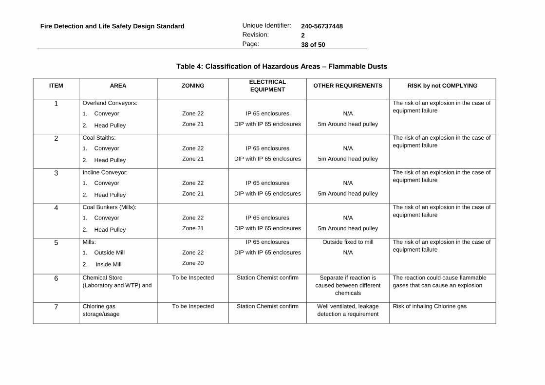
Fire Detection and Life Safety Design Standard
Unique Identifier: 240-56737448
Revision: 2
Page: 38 of 50
Table 4: Classification of Hazardous Areas – Flammable Dusts
ITEM AREA ZONING ELECTRICAL
EQUIPMENT OTHER REQUIREMENTS RISK by not COMPLYING
1 Overland Conveyors:
1. Conveyor
2. Head Pulley
Zone 22
Zone 21
IP 65 enclosures
DIP with IP 65 enclosures
N/A
5m Around head pulley
The risk of an explosion in the case of
equipment failure
2 Coal Staiths:
1. Conveyor
2. Head Pulley
Zone 22
Zone 21
IP 65 enclosures
DIP with IP 65 enclosures
N/A
5m Around head pulley
The risk of an explosion in the case of
equipment failure
3 Incline Conveyor:
1. Conveyor
2. Head Pulley
Zone 22
Zone 21
IP 65 enclosures
DIP with IP 65 enclosures
N/A
5m Around head pulley
The risk of an explosion in the case of
equipment failure
4 Coal Bunkers (Mills):
1. Conveyor
2. Head Pulley
Zone 22
Zone 21
IP 65 enclosures
DIP with IP 65 enclosures
N/A
5m Around head pulley
The risk of an explosion in the case of
equipment failure
5 Mills:
1. Outside Mill
2. Inside Mill
Zone 22
Zone 20
IP 65 enclosures
DIP with IP 65 enclosures
Outside fixed to mill
N/A
The risk of an explosion in the case of
equipment failure
6 Chemical Store
(Laboratory and WTP) and
To be Inspected Station Chemist confirm Separate if reaction is
caused between different
chemicals
The reaction could cause flammable
gases that can cause an explosion
7 Chlorine gas
storage/usage
To be Inspected Station Chemist confirm Well ventilated, leakage
detection a requirement
Risk of inhaling Chlorine gas

Fire Detection and Life Safety Design Standard
Unique Identifier: 240-56737448
Revision: 2
Page: 39 of 50
Table 5: Classification of Hazardous Areas – Flammable Vapours and Gases
ITEM AREA ZONING ELECTRICAL EQUIPMENT
OTHER REQUIREMENTS RISK by not COMPLYING
1. Petrol / Diesel Filling Stations:
1. Level detection inside tanks.
2. The pump
Zone 0
Zone 1 Zone 2
Intrinsic Safe (IS)
Flameproof (Exd IIA T1) Non-sparking (Exn IIA T1)
N/A
1,5mVert. 2,5mHoris. 5m Horis, 0,5mVert.
Failure to comply can result in an explosion due to static charges, non-compliant equipment etc.
2. Fuel Oil Tanks: 1. Inside tank
2. Outside tank
3. Inside bund walls
Zone 0 Zone 2 Zone 2
Intrinsic Safe (IS)
Non-sparking (Exn IIA T2) Non-sparking (Exn IIA T2)
N/A
If well ventilated If well ventilated
Failure to comply can result in an explosion due to static charges, non-compliant equipment etc.
3. LP Fuel Pump House: 1. LP Pump House
2. Piping
3. Delivery to Tanks
Zone 2 Zone 2 Zone 2
Non-sparking (Exn IIA T2) Non-sparking (Exn IIA T2) Non-sparking (Exn IIA T2)
N/A
1m sphere at all joints Dispensing hose earthed
Failure to comply can result in an explosion due to static charges, non-compliant equipment etc.
4 HP Fuel Pump House: 1. HP Pump House
2. Piping
Zone 2 Zone 2
Non-sparking (Exn IIA T2) Non-sparking (Exn IIA T2)
N/A
1m sphere at all joints
Failure to comply can result in an explosion due to non-compliant equipment.
5 Oil Burner Levels: 1. Oil Burners
2. Oil Burner piping
3. Propane installation
4. Propane piping
Zone 2 Zone 2 Zone 2 Zone 2
Non-sparking (Exn IIA T2) Non-sparking (Exn IIA T2) Non-sparking (Exn IIA T1) Non-sparking (Exn IIA T1)
Within 5m
1m sphere at all joints Within 5 m
1m sphere at all joints
Failure to comply can result in an explosion due to non-compliant equipment.

Fire Detection and Life Safety Design Standard
Unique Identifier: 240-56737448
Revision: 2
Page: 40 of 50
ITEM AREA ZONING ELECTRICAL EQUIPMENT
OTHER REQUIREMENTS RISK by not COMPLYING
6. H2 Unitised Plants: 1. H2 Drier
2. H2 Filling Station
3. All H2 piping
4. H2 C and I equipment
Zone 2 Zone 2 Zone 2 Zone 2
Flameproof (Exd IIC T4) Flameproof (Exd IIC T4) Flameproof (Exd IIC T4) Flameproof (Exd IIC T4)
1m sphere
Failure to comply can result in an explosion due to non-compliant equipment.
7. Generator: Below generator Stator Choke Chamber Generator Star Point
Zone 2 Zone 2 Zone 2
Flameproof (Exd IIC T4) Flameproof (Exd IIC T4) Flameproof (Exd IIC T4
Cover all pocket areas
Total area Total area
H2 can be trapped in pockets and can be ignited via electrical equipment.
8. Battery Rooms: Inside Battery Room Extraction Fan Outlet
Zone 2 Zone 2
Non-sparking (Exn IIC T4) Non-sparking (Exn IIC T4)
Ensure roof slopes outlet Mounted at highest point
H2 can be trapped in pockets and can be ignited via electrical equipment.
9. Unit/Gen Transformers: Closed up
Unit/Gen Transformer: O/C and opened
No Classification
Zone 2
No Classification
Flameproof (Exd IIC T4)
None
Adequately ventilated
None
Open flames or sparks can cause an
explosion
10. Storage of Gas Bottles: Propane G/B Store Hydrogen G/B Store Acetylene G/B Store
Zone 2 Zone 2 Zone 2
Non-sparking(Exn IIA T1) Non-sparking (Exn IIA T4) Non-sparking(Exn IIA T2)
Do not store any flammable gas in an enclosed are with
Oxygen
Open flames or sparks can cause an explosion
11. Oil Tanks: Internal - All oil tanks External – All oil tanks All piping
Zone 0 Zone 2 Zone 2
Intrinsic Safe (IS) Non-sparking (Exn IIA T1) Non-sparking (Exn IIA T1)
3m all directions
1m sphere
Open flames or sparks can cause an explosion

Fire Detection and Life Safety Design Standard
CONTROLLED DISCLOSURE When downloaded from the EDMS, this document is uncontrolled and the responsibility rests with the user to
ensure it is in line with the authorised version on the system.
Unique Identifier: 240-56737448
Revision: 2
Page: 41 of 50
8. INTERFACES TO THE FIRE DETECTION SYSTEM
Modern technology suggests the integration of various services such as access control, HVAC, CCTV, fire detection and energy management on a local, site wide and enterprise level. The integration of these services falls into the paradigm of Building Management Systems (BMS)/ SCADA Control Systems and the integration thereof is referred to as Consolidated Building Management Systems (CBMS).
The sections to follow outline recommendations and provide guidance on how an Fire Detection System can become part of a BMS/SCADA and CBMS on a local and site wide level respectively.
FDS INTERFACES (LOCAL) 8.1
All input/output (I/O) devices shall comply with EN 54-18 [25]. The FDS may be used to initiate action by other system and equipment by means of local hardwired I/O. Initiated action must follow the principle of zoning such that if a fire is detected in a certain zone, only equipment in that zone and affecting that zone is initiated. For local interfaces, the other system must receive the hardwired signal from the fire detection panel by means of a failsafe arrangement. Should any failure occur the contact will open and a fire condition will result (i.e. a failsafe system). Furthermore, the cable between the two should be fire rated and supplied by the fire detection contractor. The FDS shall only be responsible for indicating that a fire has been detected in a certain zone, other equipment is responsible for the subsequent actions that result.
A local hardwired interface to the HVAC control panel, per zone, is recommended. On detection of fire, the HVAC control panel is to close fire dampers and stop supply air fans in order to ‘choke’ the fire. This condition must remain until the fire panel is manually reset by the fire responder. The HVAC system should provide for a smoke extract sequence (manually actuated from outside of a zone) that can override the fire condition on the HVAC control panel only.
A local hardwired interface to the access control panel, per zone, is recommended. On detection of fire, the access control panel is to automatically release all electromagnetically locked doors in the zone of detection. The security personnel should be informed by the access control system that the door release is due to a detected fire and not a security breach.
A local hardwired interface to the elevator controller is recommended. On detection of a fire, the elevator controller is to bring elevators down to ground level and open the doors.
Other possible initiated action includes:
Power switching of important systems to minimize the effect of a fire (e.g. safe shutdown of servers).
Actuation of gaseous and other fire suppression systems.
Triggered CCTV streaming and recording for fire fighting.
Interlocking with other systems (e.g. stop/start conveyors, access control & gas release).
Should the HVAC, access control or any other system not have the functionality to achieve the above, the FDS shall make provision for this functionality in the future by means of unused contacts, software and/or easy expandability.

Fire Detection and Life Safety Design Standard
CONTROLLED DISCLOSURE When downloaded from the EDMS, this document is uncontrolled and the responsibility rests with the user to
ensure it is in line with the authorised version on the system.
Unique Identifier: 240-56737448
Revision: 2
Page: 42 of 50
A cause and effect analysis of the resulting sequence of events on detection of a fire must be carried out by the fire detection contractor with input from all affected system, contractors and disciplines. Furthermore, application specific routines such as time delays and voting systems (e.g. 2 out of 3) that form part of the FDS software are to be included in the cause and effect analysis. The analysis is to form part of the detailed design and must be completed and approved before design freeze. Figure 3 below provides a graphical summary of the localized interfaces to the FDS.
Figure 3: Local Fire Detection Panel Interfaces
Interfacing with other systems plays an important role in FDS and is able to increase the flexibility of the system substantially. All interfacing requirements shall be determined by the Engineer and the client.
FDS INTERFACES & NETWORKING (SITE WIDE) 8.2
All fire related alarms (including all water based and gaseous suppression system status and activations) are required to be channelled through the fire detection network to ensure compliant and effective control and indication of the wider fire detection system. Non fire related information is not to traverse by means of the fire detection network.
Figure 4 provides an overview of a FDS network and shows possible integration interfaces with HVAC, CBMS and DCS. The sections to follow provide guidance and consideration at the various levels of the network.
8.2.1 Fire Detection Network
During design of a fire detection network, the critical path of communication is defined as the path/s along which a signal will need travel in order to raise an alarm at a centralised alarming centre. The fire detection network is to be designed such that no single point of failure in communication can result in failure of the communication critical path. The most economical way to achieve this is by means of a ring topology, allowing each panel to communicate with two other panels. Star and bus topologies can also be considered, however, achieving the same level of redundancy as a ring topology will result in almost double (or more) the fibre requirements.

Fire Detection and Life Safety Design Standard
CONTROLLED DISCLOSURE When downloaded from the EDMS, this document is uncontrolled and the responsibility rests with the user to
ensure it is in line with the authorised version on the system.
Unique Identifier: 240-56737448
Revision: 2
Page: 43 of 50
The FDS network and associated equipment is to produce failure and maintenance alarms as well as status indications.
8.2.2 Fire Detection Network Routing Design
The fire detection network cabling is to be routed such that two independent physical routes exist for the critical path. This is to ensure that the cause of damage to one route is unlikely to affect the other. Furthermore, the environment through which the cables traverse is to be taken into account. Areas where damage is likely to occur should be avoided (e.g. high fire/explosion risk areas).
FIRE DETECTION SYSTEM HMI 8.3
The FDS HMI can be broken into two distant functions, namely alarming and maintenance. The alarming HMI can be either the interface of the master fire panels and/or a workstation on which graphics indicate fire alarms; it is recommended that both are used. Depending on the specific configuration of the system, HMI’s can appear on the fire detection network, one the CBMS/DCS and/or on the HVAC system.
Figure 4: FDS Site Wide Network and Interfaces

Fire Detection and Life Safety Design Standard
CONTROLLED DISCLOSURE When downloaded from the EDMS, this document is uncontrolled and the responsibility rests with the user to
ensure it is in line with the authorised version on the system.
Unique Identifier: 240-56737448
Revision: 2
Page: 44 of 50
Furthermore, it is recommended that the master fire panels are located in the same room as the alarming HMI such that the redundancies of the lower levels of the system are reflected. Suggested locations of the alarming HMI are the electrical operating desk (EOD) and the fire station. It is also beneficial for the unit/BOP operators to have an alarming interface for the specific section of plant under their control. The chosen location/s for receiving fire alarms is to be manned 24 hours a day, seven days a week.
Poor maintenance of FDS has been the root cause of failure of many FDS’s in Eskom power stations. It is therefore highly recommended that a maintenance HMI is included in every FDS. At such a workstation, all alarms (fire and maintenance) are received. The maintenance workstation should have the following functionality:
Graphical User Interface.
Logging of maintenance activity.
Recording of all alarms & events.
Repository for configuration information and system restore.
Password protected (access levels).
Escalate unattended maintenance to EOD and/or fire station.
Integrate with HVAC maintenance workstation (if not one and the same in a fully integrated solution).
HVAC INTERFACE 8.4
It is highly recommended that information is bi-directionally exchanged between the FDS system and the HVAC system by means of a bus interface. The nature of the information to be exchanged is listed below:
Failure of the local hardwired link (see section 8.1)
Status of any initiated action by the fire detection system
Critical failure/maintenance alarms
System & zones status
Resets, smoke extraction
In order to achieve the highest possible level of integration between the two systems, the following recommendation should be taken into account, in order of precedence:
HVAC controls and fire detection to be under one work package and one equipment supplier with the ability and tools to provide an integrated solution
Standardize the network protocol for both systems (BACNet, LONWorks, TCP/IP, etc.).
Make provision for the interface in future works
CBMS INTERFACE 8.5
It is recommended that, at very least, provision for an interface to a CBMS is made. The information exchanged in this interface is as follows:
Fire network fault conditions (see section 8.1).
Time synchronisation (CBMS synchronises the fire panels).
Fire Detection and Life Safety Design Standard
CONTROLLED DISCLOSURE When downloaded from the EDMS, this document is uncontrolled and the responsibility rests with the user to
ensure it is in line with the authorised version on the system.
Unique Identifier: 240-56737448
Revision: 2
Page: 45 of 50
CCTV as a fire fighting tool (switching the security cameras to the zone where smoke has been detected).
Interface for unit and BOP operators.
The following benefits arise from a CBMS solution:
Shared services such as workstations, servers and data logs.
Functionality greater than the sum of the individual subsystem functionality.
9. SYSTEM PERFORMANCE
The Fire Detection System shall comply with the station specific alarm philosophy. False alarms, alarm floods and nuisance alarms shall be kept to a minimum. The performance of the system is to be agreed upon with the contractor prior to contract award by means of Key Performance Indicators (KPIs). Suggested KPIs are as follows:
Maximum number of false alarms per day.
Maximum number of legitimate alarms per day.
Maximum time to receive an alarm.
Maximum clicks on an HMI to receive an alarm.
Availability and Reliability of the system.
The FDS system shall be kept as small as possible to optimise performance. Alarm Management is an integral part of the Generation Business risk mitigation systems and as such due diligence and good practice must be applied in all alarm or alarm system design and implementation-phases as well as during the life cycle of the alarm system. 36-963 - Alarm System Performance of Digital Control Systems Applied in Fossil Plant [14] addresses the management of alarms including FDS alarms.
10. STANDARDISATION
It is highly recommended that the entire fire detection system for the entire site is supplied, installed and commissioned by one contractor. The equipment selection should be based primarily on functionality and secondarily on a philosophy of standardisation. The application of the philosophy of standardization should aim to achieve the following:
Lower spares holding requirements.
Ease on maintenance activity.
Ease on operator and maintenance training.
Economies of scale.
In the case of refurbishment projects, it is recommended that the entire fire detection system is replaced. However, if upon thorough investigation and analysis it is found that upgrading the existing system is beneficial, the same equipment and contractor is to be used as appears in the existing system. Cognisance should be taken of the expected life span of the FDS.
No standalone fire detection systems should be installed.
When a new fire detection system is installed it is recommended that a consignment of critical spares be procured and safely stored. This will allow minimal downtime of the FDS in the event of a minor or major component failure within the system.

Fire Detection and Life Safety Design Standard
CONTROLLED DISCLOSURE When downloaded from the EDMS, this document is uncontrolled and the responsibility rests with the user to
ensure it is in line with the authorised version on the system.
Unique Identifier: 240-56737448
Revision: 2
Page: 46 of 50
Typically a list of critical spares would be:
One complete main Fire Detection Panel
One complete sub Fire Detection Panel
Main power supply unit and battery charger for the main and sub panels
Loop Control Module
Network Communication Module
Smoke Detectors
Manual Call Points
Heat Detectors
Annunciators
Strobes
The FDS Contractor is to be engaged at tender stage to determine the extent of the spares required as well as determining the quantity of spares required based on an average mean-time-between-failure study.
11. COMMISSIONING AND HAND-OVER, INSPECTION, TESTING, AND MAINTENANCE
COMMISSIONING AND HAND-OVER 11.1
A typical FDS installation project will follow the below mentioned steps:
Project implementation phases and acceptance
i. Investigation phase
ii. Design and engineering phase
- Technical clarification stage.
- Design freeze stage
iii. Production engineering phase
- Procurement, fabrication and delivery stage.
- Factory acceptance test stage (FAT)
iv. Construction and erection phase.
v. Commissioning phase
- SIT stage
- Commissioning stage.
- SAT stage.
vi. Operational test phase.
Codification and labelling of plant
Training of the Employer’s and other relevant staff
Quality assurance and control
As-build documentation, drawings manuals and schedules

Fire Detection and Life Safety Design Standard
CONTROLLED DISCLOSURE When downloaded from the EDMS, this document is uncontrolled and the responsibility rests with the user to
ensure it is in line with the authorised version on the system.
Unique Identifier: 240-56737448
Revision: 2
Page: 47 of 50
All components of the FDS shall be coded and labelled according to the station specific KKS or AKZ standard.
INSPECTION, TESTING AND MAINTENANCE 11.2
Inspection, Testing and Maintenance of all Fire Detection and Alarm Systems shall be in accordance with manufacturer’s recommendations and the guidance provided within 240-56737654 - Inspection, Testing & Maintenance of Fire Detection Systems [5].
DOCUMENTATION 11.3
In accordance with SANS 10139 [7] the FDS contractor shall develop and provide the following documentation to Eskom for approval prior to completion of system commissioning:
Detailed as-built drawings;
A comprehensive Operation and Maintenance Manual for the entire system;
Certificates for Design, Installation and Commissioning according to SANS 10139 [7] Appendix G;
Insurance, guarantee and warrantee certificates;
All programming data, including how the programming was carried out, who was responsible, double knock rules, conditional programming, inputs/outputs, special cause and affect situations, etc.;
Fire detection philosophy, including detection zones, double-knock rules, etc.
Alarm philosophy, including alarm management and responses, alarm zones, additional alarms, fire department notification, etc.
Detailed specifications of all materials and equipment used;
Electrical Certificate of Completion (COC);
Log Book, according to SANS 10139 [7] Appendix F;
Record of agreed variations from the original design specification;
Framed zone diagrams adjacent to each control panel;
Network Architecture Drawings
Master Document List
Life Cycle Cost Report
Standardization Philosophy Report
Reliability, Availability and Maintainability (RAM) Study
Limits of Supply and Services (LOSS)
Inspection Test Plan, Factory Acceptance Test, Site Integration Test
Commissioning Strategy
Virtual Signals List
Panel Interface List
Instrument List

Fire Detection and Life Safety Design Standard
CONTROLLED DISCLOSURE When downloaded from the EDMS, this document is uncontrolled and the responsibility rests with the user to
ensure it is in line with the authorised version on the system.
Unique Identifier: 240-56737448
Revision: 2
Page: 48 of 50
Electrical Consumer List
Electrical Wiring Diagram (Single Lines)
Mechanical Mounting or Connection Diagrams
Cubicle Internal Layouts and Details (Size, Weight, Cable Entry, Heat Load etc.)
Fire Risk Assessment
Cause and Effect Analysis
Alarm List and Response Procedure
Alarm Rationalisation Philosophy
HMI Graphical Displays
Recommended Spares Holding
Earthing, Lightning Protection and Electromagnetic Compliance Details
UPS/Battery Back Up Details
Cable Schedule
Cable Routing Design
Document management procedure
Detailed Design with all Engineering Calculations
Software List
Software Licensing and Certificates
All documentation required shall be listed in a Vendor Document Submittal Schedule (VDSS), to be produced by Eskom, and agreed upon with the contractor prior to contract award. The VDSS shall give a description of the documents required and the stage/s in the project life cycle at which the document is required.
The applicable Eskom drawing standard shall be submitted to the contractor and all drawings shall comply with the requirements therein.
12. AUTHORISATION
This document has been seen and accepted by:
Marlize Andre Fire & Life Safety C/G Member [email protected]
Matthew Collier Fire & Life Safety C/G Member [email protected]
Cobus Dippenaar Fire & Life Safety C/G Member [email protected]
Marius Atterbury Fire & Life Safety C/G Member [email protected]
Mbali Mathebula Fire & Life Safety C/G Member [email protected]
Jorge Nunes Fire & Life Safety C/G Member [email protected]
Andre van den Berg Fire & Life Safety C/G Member [email protected]
Warren Reid Fire & Life Safety C/G Member [email protected]
Brian Lintnaar Fire & Life Safety C/G Member [email protected]
Mamosa Mosebo Fire & Life Safety C/G Participant [email protected]

Fire Detection and Life Safety Design Standard
CONTROLLED DISCLOSURE When downloaded from the EDMS, this document is uncontrolled and the responsibility rests with the user to
ensure it is in line with the authorised version on the system.
Unique Identifier: 240-56737448
Revision: 2
Page: 49 of 50
Mphephu Nengovhela Fire & Life Safety C/G Participant [email protected]
Siyabonga Zwane Fire & Life Safety C/G Participant [email protected]
Cinga Mhlongo Fire & Life Safety C/G Participant [email protected]
Lyborn Xivambu Fire & Life Safety C/G Participant [email protected]
Wesley Nkwinika Fire & Life Safety C/G Participant [email protected]
Cindy Ndlangisa Fire & Life Safety C/G Participant [email protected]
Viona Lutchminarain Fire & Life Safety C/G Participant [email protected]
Seshni Pillay Fire & Life Safety C/G Participant [email protected]
Nelly Hlophe Fire & Life Safety C/G Participant [email protected]
Bernard vd Westhuizen Fire & Life Safety C/G Participant [email protected]
Theodore Subramoney Fire & Life Safety C/G Participant [email protected]
Alusani Ndou Fire & Life Safety C/G Participant [email protected]
Christinah Mukondeleli Fire & Life Safety C/G Participant [email protected]
Reymond Mogajane Fire & Life Safety C/G Participant [email protected]
Mauritz Van Der Bank Fire & Life Safety C/G Participant [email protected]
Didi Tselane Fire & Life Safety C/G Participant [email protected]
Nsizwa Mhlongo Fire & Life Safety C/G Participant [email protected]
Henri Kotze Fire & Life Safety C/G Participant [email protected]
Simphiwe Kubheka Fire & Life Safety C/G Participant [email protected]
Kamogelo Lefifi Fire & Life Safety C/G Participant [email protected]
Phaks Antoni Fire & Life Safety C/G Participant [email protected]
Zanele Mani Fire & Life Safety C/G Participant [email protected]
Mohammed Sardiwalla Fire & Life Safety C/G Participant [email protected]
Nompilo Miya Fire & Life Safety C/G Participant [email protected]
Sibusiso Ngcobo Fire & Life Safety C/G Participant [email protected]
Tiisetso Ntlatleng Fire & Life Safety C/G Participant [email protected]
Nombuyiselo Molosiwa Kendal C&I Engineer [email protected]
Peter May Fire Risk Management [email protected]
Hardus Viljoen Fire Risk Management [email protected]
Marius Engelbrecht Fire Risk Management [email protected]
Danie Odendaal GM Plant Engineering [email protected]
Prince Moyo GM Power Delivery [email protected]
Titus Mathe SM Power Plant [email protected]
Prudence Madiba SM Electrical and C&I [email protected]
Vasanie Pather SM Auxiliary and Chemical [email protected]

Fire Detection and Life Safety Design Standard
CONTROLLED DISCLOSURE When downloaded from the EDMS, this document is uncontrolled and the responsibility rests with the user to
ensure it is in line with the authorised version on the system.
Unique Identifier: 240-56737448
Revision: 2
Page: 50 of 50
Galia Dudenska SM Civil, Structural and Hydro [email protected]
Louis Fernandez SM Integration [email protected]
This document has been seen and accepted by: Power Delivery Engineering SCOT
13. REVISIONS
Date Rev. Compiler Remarks
November 2012 0 M D Collier First draft for comment
January 2013 0.1 M D Collier Second draft for comment
March 2013 0.2 M D Collier Final draft for comment
July 2013 1 M D Collier Final Document for Authorisation
May 2014 1.1 Andre vd Berg Scheduled Review process by Fire & Life Safety Care Group
June 2014 1.2 Andre vd Berg Incorporate review comments from formal document review process.
October 2014 1.3 Andre vd Berg Incorporate review comments from LPS Study Group, draft for 2nd Review
October 2014 1.4 Andre vd Berg Updated Final Draft after 2nd formal Review
October 2014 2 Andre vd Berg Final Document for Authorisation and Publication
14. DEVELOPMENT TEAM
The following people were involved in the development of this document:
Marlize Andre – Eskom Group Technology
Matthew Collier - Eskom Group Technology
Jorge Nunes – Eskom C&I
Richelle Ramraj – Eskom Group Technology
Karel Roodt - WSP Group Africa (Pty) Ltd
Ryan Visser – WSP Group Africa (Pty) Ltd
Frank Mendham – WSP Asia Pacific (Pty) Ltd
Walther Groenewald – WSP Asia Pacific (Pty) Ltd
15. ACKNOWLEDGEMENTS
Abrie Nieuwoudt C&I Application
Andre van den Berg C&I Plant CoE
Marius Atterbury Snr Advisor Occ Health and Safety
Marius Engelbrecht Snr Advisor Fire Risk Management
Mauritz van der Bank C&I Engineering Manager Arnot P/S