fire installation manual - mgo corp pty. ltd.mgoboard.com.au/.../04/installation-manual-aus.pdf ·...
TRANSCRIPT

Fire Installation Manual
Contents
BCA Codes 3
General 4
Fire Performances
Thermal and Acoustic Insulation
Wall Installation 4
Timber Frame Separation Walls 5
Steel Frame Separation Walls 6
External Fire Rated Walls 7
Floor Installation 8
Ceiling Installation 9
Timber framing to be installed in accordance with AS:1684
Metal framing to be installed in accordance with BCA Volume: 2
Extract of ResCom Testing to the BCA:
• BCA Volume One 2013:
• Part C1.8 Light Weight Construction,
• C1.10 Fire Hazard including NSW State Variation,
• C1.12 Non-Combustible materials
• Load bearing Timber Frame
60/60/60 utilising 10mm ResCom(R)
• Load bearing Metal Frame
90/90/90 utilising 10mm ResCom(R)
• Non-load bearing walls FRL (Single board
performance)
5mm -/20/20
10mm -/60/60
10mm -/90/90
12mm -/120/120
14mm - /180/180
15mm -/240/240
18mm Structural Flooring
120/120/120
• BCA Volume One 2013: Part F5 Sound Insulation
to Rw 60+ctr
• BCA Volume Two 2013: Part 3.5.3.3, Fibre cement
planks and weatherboard cladding.
• BCA Volume Two 2013: Part 3.5.3.4, Fibre cement
sheet wall cladding.
• BCA Volume Two 2013: Part 3.5.3.5, Eaves and
soffit linings.
• BCA Volume Two 2013: Part 3.7.1, Fire separation
for FRL to (load bearing timber frame 60/60/60,
load bearing metal frame 90/90/90, non-load
bearing FRL -/120/120) – including SA state
variation.
• BCA Volume Two 2013: Part 3.7.4, Bushfire areas
including all state variations to Part 3.7.4.0 and
3.7.4.1, as tested under AS1530 Part 8.1 - 2007
and AS1530 Part 8.2 - 2007 – including NSW state
variation, SA state variation. TAS state variation.
• BCA Volume Two 2013: Part 3.8.6, Sound
insulation to RW 64+ctr
more information go to www.mgoboard.com.au or by emailing [email protected]
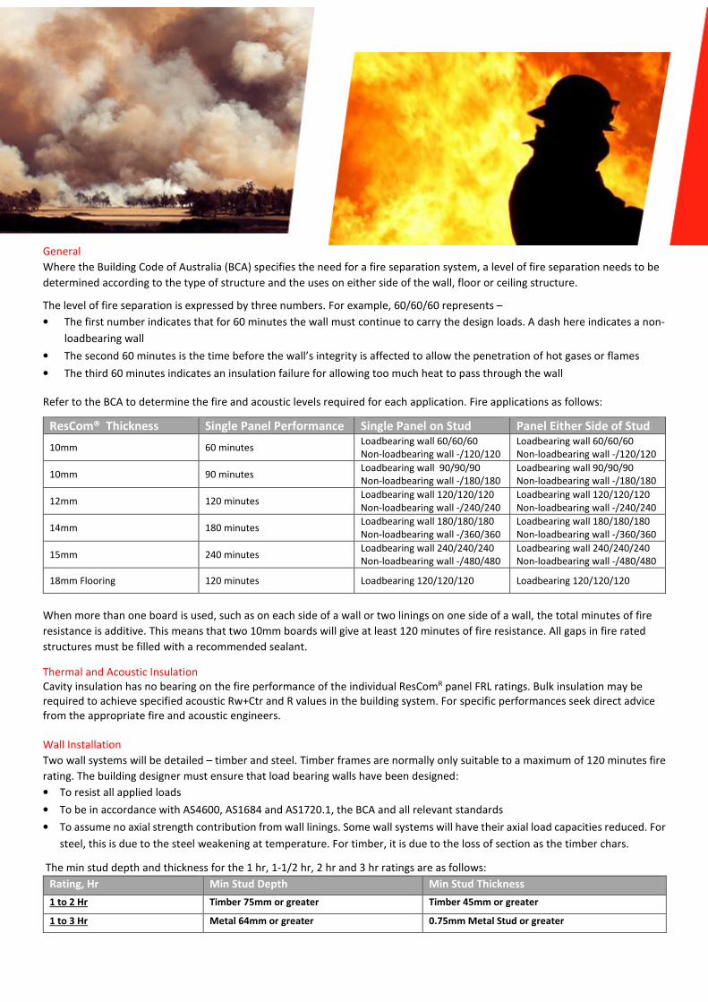
General
Where the Building Code of Australia (BCA) specifies the need for a fire separation system, a level of fire separation needs to be
determined according to the type of structure and the uses on either side of the wall, floor or ceiling structure.
The level of fire separation is expressed by three numbers. For example, 60/60/60 represents –
• The first number indicates that for 60 minutes the wall must continue to carry the design loads. A dash here indicates a non-
loadbearing wall
• The second 60 minutes is the time before the wall’s integrity is affected to allow the penetration of hot gases or flames
• The third 60 minutes indicates an insulation failure for allowing too much heat to pass through the wall
Refer to the BCA to determine the fire and acoustic levels required for each application. Fire applications as follows:
ResCom® Thickness Single Panel Performance Single Panel on Stud Panel Either Side of Stud
10mm 60 minutes Loadbearing wall 60/60/60
Non-loadbearing wall -/120/120
Loadbearing wall 60/60/60
Non-loadbearing wall -/120/120
10mm 90 minutes Loadbearing wall 90/90/90
Non-loadbearing wall -/180/180
Loadbearing wall 90/90/90
Non-loadbearing wall -/180/180
12mm 120 minutes Loadbearing wall 120/120/120
Non-loadbearing wall -/240/240
Loadbearing wall 120/120/120
Non-loadbearing wall -/240/240
14mm 180 minutes Loadbearing wall 180/180/180
Non-loadbearing wall -/360/360
Loadbearing wall 180/180/180
Non-loadbearing wall -/360/360
15mm 240 minutes Loadbearing wall 240/240/240
Non-loadbearing wall -/480/480
Loadbearing wall 240/240/240
Non-loadbearing wall -/480/480
18mm Flooring 120 minutes Loadbearing 120/120/120 Loadbearing 120/120/120
When more than one board is used, such as on each side of a wall or two linings on one side of a wall, the total minutes of fire
resistance is additive. This means that two 10mm boards will give at least 120 minutes of fire resistance. All gaps in fire rated
structures must be filled with a recommended sealant.
Thermal and Acoustic Insulation
Cavity insulation has no bearing on the fire performance of the individual ResComR panel FRL ratings. Bulk insulation may be
required to achieve specified acoustic Rw+Ctr and R values in the building system. For specific performances seek direct advice
from the appropriate fire and acoustic engineers.
Wall Installation
Two wall systems will be detailed – timber and steel. Timber frames are normally only suitable to a maximum of 120 minutes fire
rating. The building designer must ensure that load bearing walls have been designed:
• To resist all applied loads
• To be in accordance with AS4600, AS1684 and AS1720.1, the BCA and all relevant standards
• To assume no axial strength contribution from wall linings. Some wall systems will have their axial load capacities reduced. For
steel, this is due to the steel weakening at temperature. For timber, it is due to the loss of section as the timber chars.
The min stud depth and thickness for the 1 hr, 1-1/2 hr, 2 hr and 3 hr ratings are as follows:
Rating, Hr Min Stud Depth Min Stud Thickness
1 to 2 Hr Timber 75mm or greater Timber 45mm or greater
1 to 3 Hr Metal 64mm or greater 0.75mm Metal Stud or greater
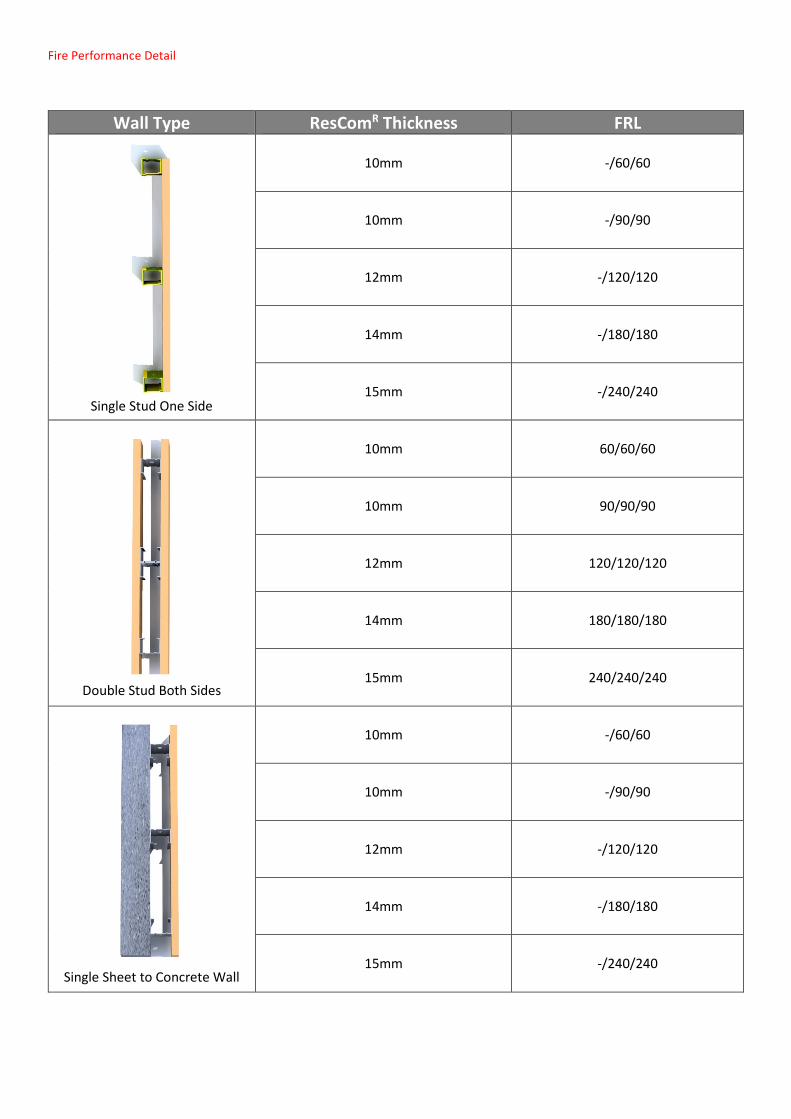
Fire Performance Detail
Wall Type ResComR Thickness FRL
Single Stud One Side
10mm -/60/60
10mm -/90/90
12mm -/120/120
14mm -/180/180
15mm -/240/240
Double Stud Both Sides
10mm 60/60/60
10mm 90/90/90
12mm 120/120/120
14mm 180/180/180
15mm 240/240/240
Single Sheet to Concrete Wall
10mm -/60/60
10mm -/90/90
12mm -/120/120
14mm -/180/180
15mm -/240/240
Timber Frame Separation Walls. The maximum timber stud heights for applied loads of 15 kN/m and recommended stud spacing
maximum 600mm on fire rated wall systems.
The following are important points to observe
• Sheets can be fixed using a combination of screws and
appropriate structural adhesive.
• Where a double wall system is used, the gap between
the walls should be from a minimum of 20mm to a
maximum of 50mm.
• Screws will be non-corrosive class 3 to 5 No.8 x 40 self-
drilling countersunk type, and will finish at approx.
0.5mm below the surface. MgO Corp recommends a
minimum grade 316 stainless steel non-corrosive
fixtures to be used in corrosive areas.
• On sheet corners, keep the first screw 50mm from the
edge to avoid breakage of the sheet.
• Control joints are to be used where specified, where
dissimilar materials abut, or at least every 12 metres.
Timber frames are normally only suitable to a maximum of
120 minute fire rating.
The building designer must ensure that load bearing walls
have been designed:
• To resist all applied loads
• To be in accordance with AS4600, AS1684 and ASl720.1,
the BCA and all relevant standards
• To assume no axial strength contribution form wall
linings. Some wall systems will have their axial load
capacities reduced. For timber, it is due to the loss of
section as the timber chars.
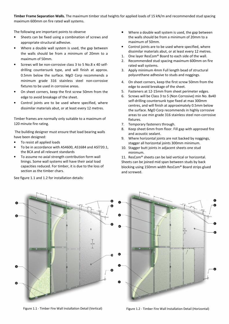
See figure 1.1 and 1.2 for installation details:
• Where a double wall system is used, the gap between
the walls should be from a minimum of 20mm to a
maximum of 50mm.
• Control joints are to be used where specified, where
dissimilar materials abut, or at least every 12 metres.
1. One layer ResCom® Board to each side of the wall.
2. Recommended stud spacing maximum 600mm on fire
rated wall systems.
3. Apply minimum 4mm Full length bead of structural
polyurethane adhesive to studs and noggings.
4. On sheet corners, keep the first screw 50mm from the
edge to avoid breakage of the sheet.
5. Fasteners at 12-15mm from sheet perimeter edges.
6. Screws will be Class 3 to 5 (Non Corrosive) min No. 8x40
self-drilling countersunk type fixed at max 300mm
centres, and will finish at approximately 0.5mm below
the surface. MgO Corp recommends in highly corrosive
areas to use min grade 316 stainless steel non-corrosive
fixtures.
7. Temporary fasteners through.
8. Keep sheet 6mm from floor. Fill gap with approved fire
and acoustic sealant.
9. Where horizontal joints are not backed by noggings,
stagger all horizontal joints 300mm minimum.
10. Stagger butt joints in adjacent sheets one stud
minimum.
11. ResCom® sheets can be laid vertical or horizontal.
Sheets can be joined mid span between studs by back
blocking using 150mm width ResCom® Board strips glued
and screwed.
Figure 1.1 - Timber Fire Wall Installation Detail (Vertical) Figure 1.2 - Timber Fire Wall Installation Detail (Horizontal)
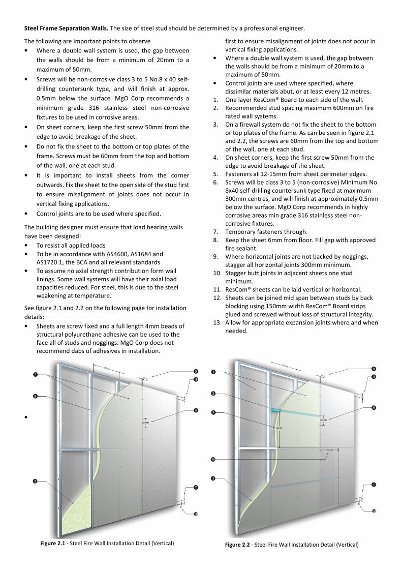
Steel Frame Separation Walls. The size of steel stud should be determined by a professional engineer.
The following are important points to observe
• Where a double wall system is used, the gap between
the walls should be from a minimum of 20mm to a
maximum of 50mm.
• Screws will be non-corrosive class 3 to 5 No.8 x 40 self-
drilling countersunk type, and will finish at approx.
0.5mm below the surface. MgO Corp recommends a
minimum grade 316 stainless steel non-corrosive
fixtures to be used in corrosive areas.
• On sheet corners, keep the first screw 50mm from the
edge to avoid breakage of the sheet.
• Do not fix the sheet to the bottom or top plates of the
frame. Screws must be 60mm from the top and bottom
of the wall, one at each stud.
• It is important to install sheets from the corner
outwards. Fix the sheet to the open side of the stud first
to ensure misalignment of joints does not occur in
vertical fixing applications.
• Control joints are to be used where specified.
The building designer must ensure that load bearing walls
have been designed:
• To resist all applied loads
• To be in accordance with AS4600, AS1684 and
AS1720.1, the BCA and all relevant standards
• To assume no axial strength contribution form wall
linings. Some wall systems will have their axial load
capacities reduced. For steel, this is due to the steel
weakening at temperature.
See figure 2.1 and 2.2 on the following page for installation
details:
• Sheets are screw fixed and a full length 4mm beads of
structural polyurethane adhesive can be used to the
face all of studs and noggings. MgO Corp does not
recommend dabs of adhesives in installation.
• It is important to install sheets from the corner
outwards. Fix the sheet to the open side of the stud
first to ensure misalignment of joints does not occur in
vertical fixing applications.
• Where a double wall system is used, the gap between
the walls should be from a minimum of 20mm to a
maximum of 50mm.
• Control joints are used where specified, where
dissimilar materials abut, or at least every 12 metres.
1. One layer ResCom® Board to each side of the wall.
2. Recommended stud spacing maximum 600mm on fire
rated wall systems.
3. On a firewall system do not fix the sheet to the bottom
or top plates of the frame. As can be seen in figure 2.1
and 2.2, the screws are 60mm from the top and bottom
of the wall, one at each stud.
4. On sheet corners, keep the first screw 50mm from the
edge to avoid breakage of the sheet.
5. Fasteners at 12-15mm from sheet perimeter edges.
6. Screws will be class 3 to 5 (non-corrosive) Minimum No.
8x40 self-drilling countersunk type fixed at maximum
300mm centres, and will finish at approximately 0.5mm
below the surface. MgO Corp recommends in highly
corrosive areas min grade 316 stainless steel non-
corrosive fixtures.
7. Temporary fasteners through.
8. Keep the sheet 6mm from floor. Fill gap with approved
fire sealant.
9. Where horizontal joints are not backed by noggings,
stagger all horizontal joints 300mm minimum.
10. Stagger butt joints in adjacent sheets one stud
minimum.
11. ResCom® sheets can be laid vertical or horizontal.
12. Sheets can be joined mid span between studs by back
blocking using 150mm width ResCom® Board strips
glued and screwed without loss of structural integrity.
13. Allow for appropriate expansion joints where and when
needed.
Figure 2.1 - Steel Fire Wall Installation Detail (Vertical) Figure 2.2 - Steel Fire Wall Installation Detail (Vertical)
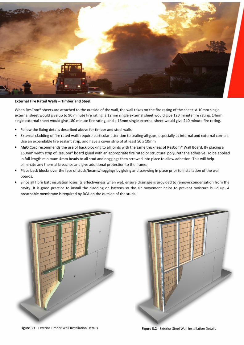
External Fire Rated Walls – Timber and Steel.
When ResCom® sheets are attached to the outside of the wall, the wall takes on the fire rating of the sheet. A 10mm single
external sheet would give up to 90 minute fire rating, a 12mm single external sheet would give 120 minute fire rating, 14mm
single external sheet would give 180 minute fire rating, and a 15mm single external sheet would give 240 minute fire rating.
• Follow the fixing details described above for timber and steel walls
• External cladding of fire rated walls require particular attention to sealing all gaps, especially at internal and external corners.
Use an expandable fire sealant strip, and have a cover strip of at least 50 x 10mm
• MgO Corp recommends the use of back blocking to all joints with the same thickness of ResCom® Wall Board. By placing a
150mm width strip of ResCom® board glued with an appropriate fire rated or structural polyurethane adhesive. To be applied
in full length minimum 4mm beads to all stud and noggings then screwed into place to allow adhesion. This will help
eliminate any thermal breaches and give additional protection to the frame.
• Place back blocks over the face of studs/beams/noggings by gluing and screwing in place prior to installation of the wall
boards.
• Since all fibre batt insulation loses its effectiveness when wet, ensure drainage is provided to remove condensation from the
cavity. It is good practice to install the cladding on battens so the air movement helps to prevent moisture build up. A
breathable membrane is required by BCA on the outside of the studs.
Figure 3.1 - Exterior Timber Wall Installation Details Figure 3.2 - Exterior Steel Wall Installation Details

Figure 4.1, 4.2, 4.3: Wall Lining Back Blocking Options
1. MgO Corp ResComR Board
2. Framing or batons
3. MgO Corp ResComR Board back blocking at least 200mm width centred over joints
4. Butt joint centred between framing member
Figure 4.1 Figure 4.2 Figure 4.3
Floor Installation
ResCom® flooring sheets have the same impressive fire properties as the wall sheets. When combined with ResCom® ceiling
sheets, the floor structure can be protected from the effects of fire. The normal floor sheet thicknesses start at 18mm, and can
range up to 50mm for special applications. See the flooring technical data sheet for assistance to select the correct floor for your
application.
The level of fire protection (up to 180 minutes) is set by the ceiling material, since the flooring sheets already exceed the minimum
requirements for 120 minute rating.
FRL Floor Rating Floor Sheet FRL Ceiling Rating Ceiling
90 min 14mm 60 min 10mm
120 min 18mm 90 min 10mm
150 min 20mm 120 min 12mm
180 min 25mm 180 min 14mm
Normally the acoustic performance of the floor requires particular attention to material choices and method of installation. The
floor design must exceed the ‘Deemed to Satisfy’ requirements of the BCA Part 5 ‘Sound Transmissions and Insulations, Class 2 or
3 Buildings. Floors under this requirement must have a Ln,w no higher than 62. The depth of the floor, type of floor joist, insulation
type and thickness and floor finishing materials affect the acoustic performance. It is recommended to design a carpeted floor as
per a hard floor, so that the acoustic performance is satisfactory in the future if the carpet is replaced with tiles or timber.
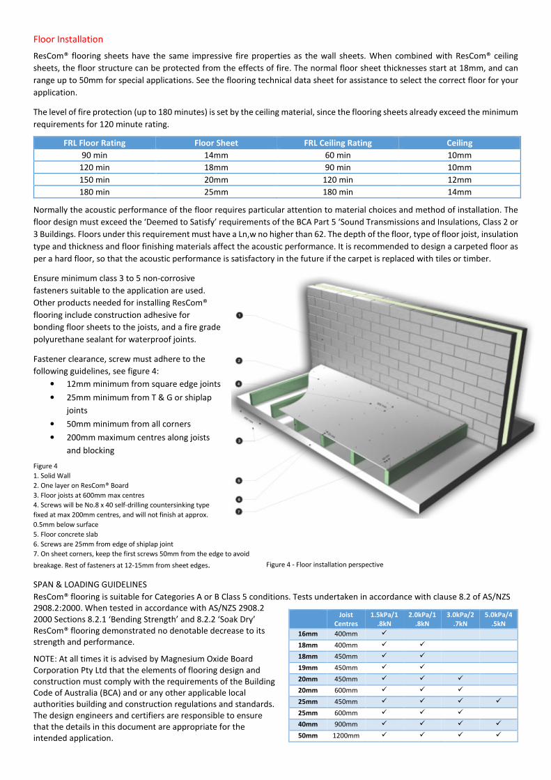
Ensure minimum class 3 to 5 non-corrosive
fasteners suitable to the application are used.
Other products needed for installing ResCom®
flooring include construction adhesive for
bonding floor sheets to the joists, and a fire grade
polyurethane sealant for waterproof joints.
Fastener clearance, screw must adhere to the
following guidelines, see figure 4:
• 12mm minimum from square edge joints
• 25mm minimum from T & G or shiplap
joints
• 50mm minimum from all corners
• 200mm maximum centres along joists
and blocking
Figure 4
1. Solid Wall
2. One layer on ResCom® Board
3. Floor joists at 600mm max centres
4. Screws will be No.8 x 40 self-drilling countersinking type
fixed at max 200mm centres, and will not finish at approx.
0.5mm below surface
5. Floor concrete slab
6. Screws are 25mm from edge of shiplap joint
7. On sheet corners, keep the first screws 50mm from the edge to avoid
breakage. Rest of fasteners at 12-15mm from sheet edges.
SPAN & LOADING GUIDELINES
ResCom® flooring is suitable for Categories A or B Class 5 conditions. Tests undertaken in accordance with clause 8.2 of AS/NZS
2908.2:2000. When tested in accordance with AS/NZS 2908.2
2000 Sections 8.2.1 ‘Bending Strength’ and 8.2.2 ‘Soak Dry’
ResCom® flooring demonstrated no denotable decrease to its
strength and performance.
NOTE: At all times it is advised by Magnesium Oxide Board
Corporation Pty Ltd that the elements of flooring design and
construction must comply with the requirements of the Building
Code of Australia (BCA) and or any other applicable local
authorities building and construction regulations and standards.
The design engineers and certifiers are responsible to ensure
that the details in this document are appropriate for the
intended application.
Joist
Centres
1.5kPa/1
.8kN
2.0kPa/1
.8kN
3.0kPa/2
.7kN
5.0kPa/4
.5kN
16mm 400mm �
18mm 400mm � �
18mm 450mm � �
19mm 450mm � �
20mm 450mm � � �
20mm 600mm � � �
25mm 450mm � � � �
25mm 600mm � � �
40mm 900mm � � � �
50mm 1200mm � � � �
Figure 4 - Floor installation perspective
view
Ceiling Installation
ResCom® ceiling sheet thicknesses
have been tabulated for 60 to 180
minute applications in the “Floors”
section above. To minimise joint
movement, and reduce the transfer of
sound, it is recommended to always fix
to metal ceiling battens. When
additional acoustic isolation is
required, resilient mounts are used to
fix the battens.
ResCom® ceiling sheets are installed as
per the wall sheets on fire separation
walls. Refer to the section on “Walls”
above.
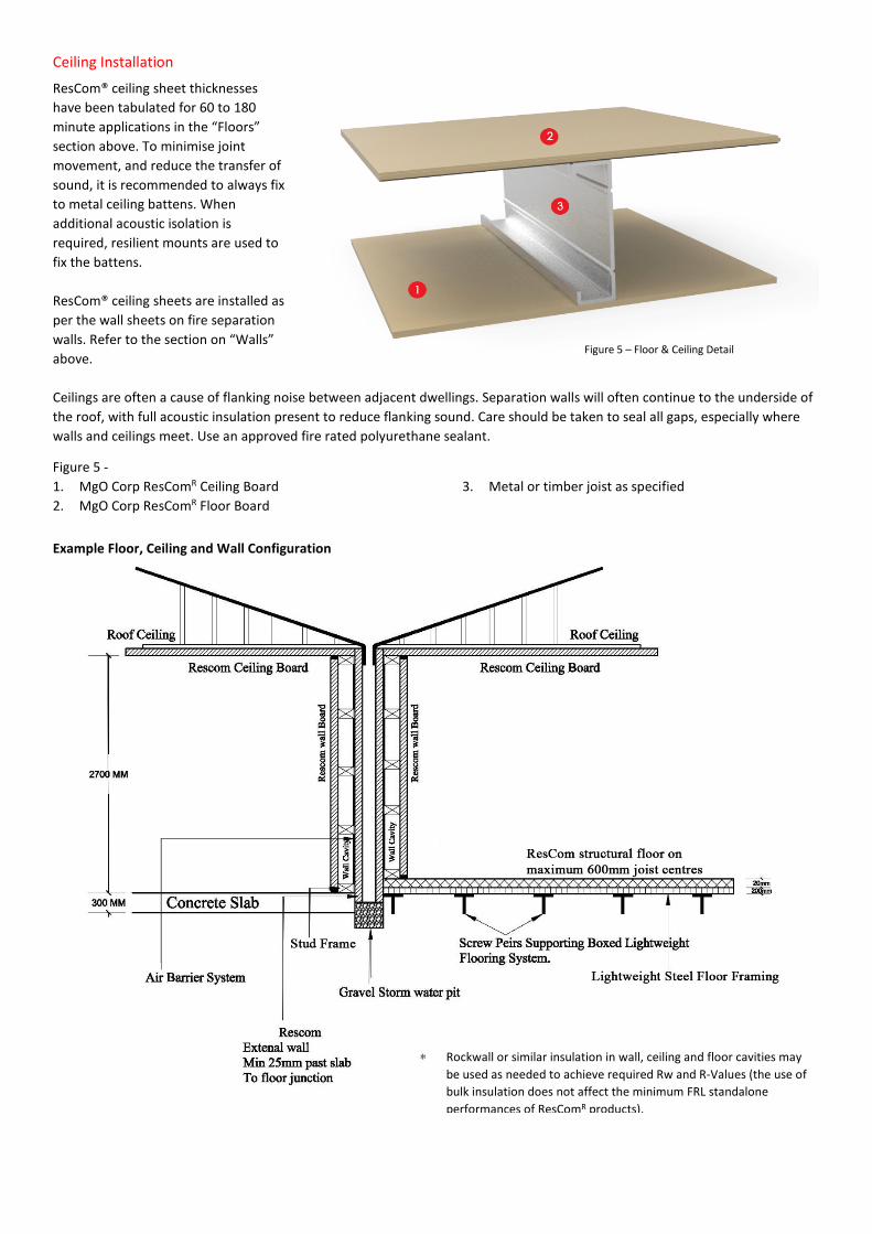
Ceilings are often a cause of flanking noise between adjacent dwellings. Separation walls will often continue to the underside of
the roof, with full acoustic insulation present to reduce flanking sound. Care should be taken to seal all gaps, especially where
walls and ceilings meet. Use an approved fire rated polyurethane sealant.
Figure 5 -
1. MgO Corp ResComR Ceiling Board
2. MgO Corp ResComR Floor Board
3. Metal or timber joist as specified
Example Floor, Ceiling and Wall Configuration
Figure 5 – Floor & Ceiling Detail
∗ Rockwall or similar insulation in wall, ceiling and floor cavities may
be used as needed to achieve required Rw and R-Values (the use of
bulk insulation does not affect the minimum FRL standalone
performances of ResComR products).
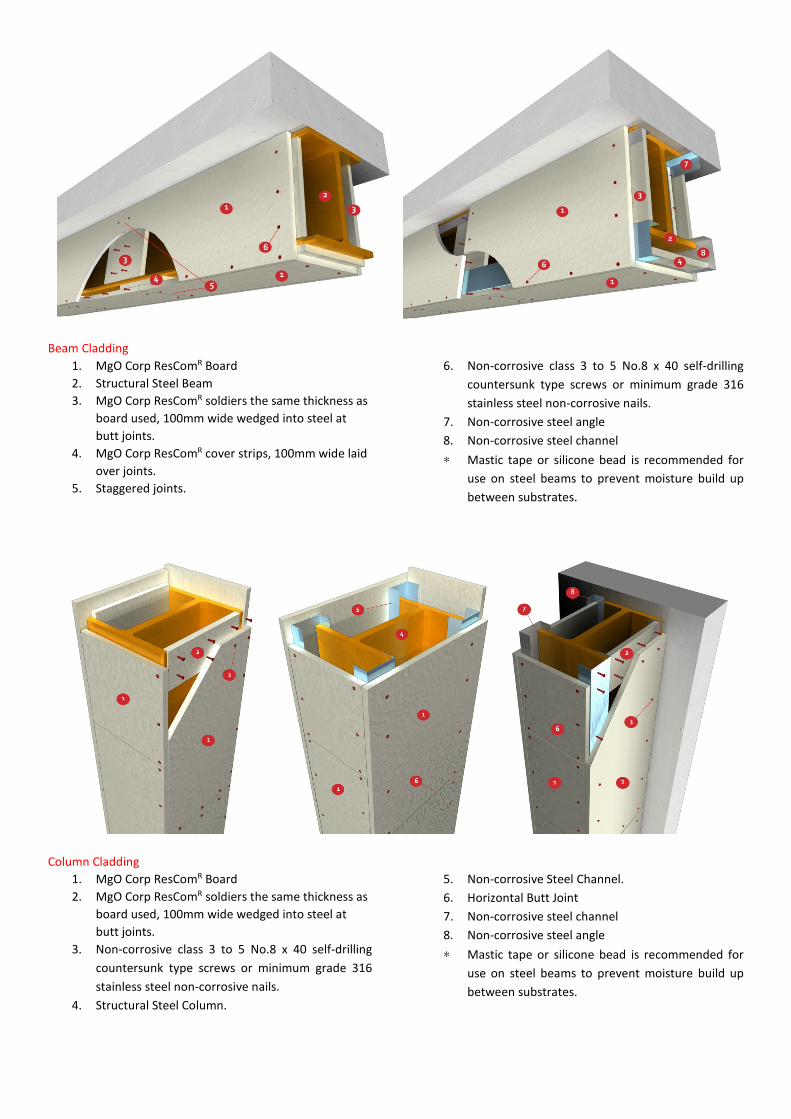
Beam Cladding
1. MgO Corp ResComR Board
2. Structural Steel Beam
3. MgO Corp ResComR soldiers the same thickness as
board used, 100mm wide wedged into steel at
butt joints.
4. MgO Corp ResComR cover strips, 100mm wide laid
over joints.
5. Staggered joints.
6. Non-corrosive class 3 to 5 No.8 x 40 self-drilling
countersunk type screws or minimum grade 316
stainless steel non-corrosive nails.
7. Non-corrosive steel angle
8. Non-corrosive steel channel
∗ Mastic tape or silicone bead is recommended for
use on steel beams to prevent moisture build up
between substrates.
Column Cladding
1. MgO Corp ResComR Board
2. MgO Corp ResComR soldiers the same thickness as
board used, 100mm wide wedged into steel at
butt joints.
3. Non-corrosive class 3 to 5 No.8 x 40 self-drilling
countersunk type screws or minimum grade 316
stainless steel non-corrosive nails.
4. Structural Steel Column.
5. Non-corrosive Steel Channel.
6. Horizontal Butt Joint
7. Non-corrosive steel channel
8. Non-corrosive steel angle
∗ Mastic tape or silicone bead is recommended for
use on steel beams to prevent moisture build up
between substrates.
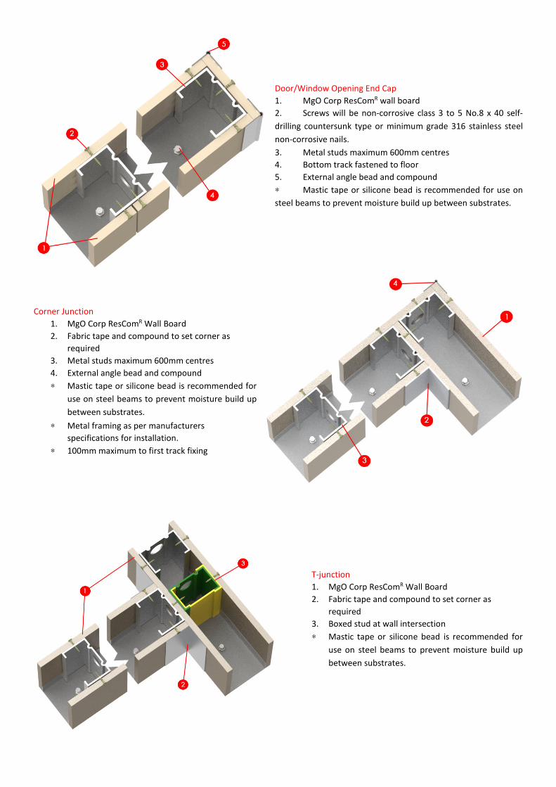
Door/Window Opening End Cap
1. MgO Corp ResComR wall board
2. Screws will be non-corrosive class 3 to 5 No.8 x 40 self-
drilling countersunk type or minimum grade 316 stainless steel
non-corrosive nails.
3. Metal studs maximum 600mm centres
4. Bottom track fastened to floor
5. External angle bead and compound
∗ Mastic tape or silicone bead is recommended for use on
steel beams to prevent moisture build up between substrates.
Corner Junction
1. MgO Corp ResComR Wall Board
2. Fabric tape and compound to set corner as
required
3. Metal studs maximum 600mm centres
4. External angle bead and compound
∗ Mastic tape or silicone bead is recommended for
use on steel beams to prevent moisture build up
between substrates.
∗ Metal framing as per manufacturers
specifications for installation.
∗ 100mm maximum to first track fixing
T-junction
1. MgO Corp ResComR Wall Board
2. Fabric tape and compound to set corner as
required
3. Boxed stud at wall intersection
∗ Mastic tape or silicone bead is recommended for
use on steel beams to prevent moisture build up
between substrates.
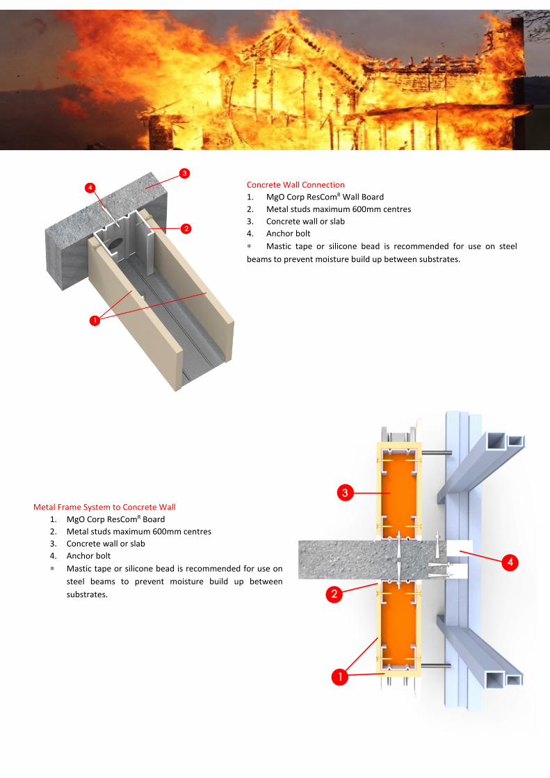
Concrete Wall Connection
1. MgO Corp ResComR Wall Board
2. Metal studs maximum 600mm centres
3. Concrete wall or slab
4. Anchor bolt
∗ Mastic tape or silicone bead is recommended for use on steel
beams to prevent moisture build up between substrates.
Metal Frame System to Concrete Wall
1. MgO Corp ResComR Board
2. Metal studs maximum 600mm centres
3. Concrete wall or slab
4. Anchor bolt
∗ Mastic tape or silicone bead is recommended for use on
steel beams to prevent moisture build up between
substrates.
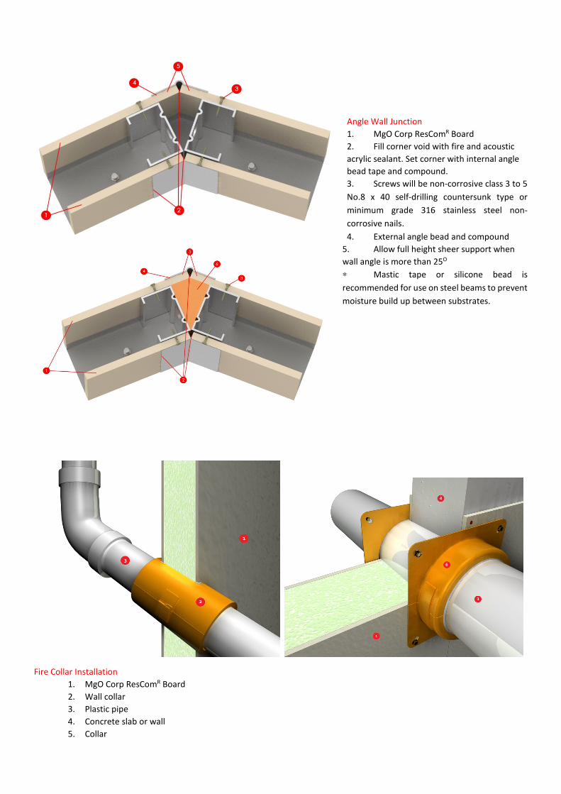
Angle Wall Junction
1. MgO Corp ResComR Board
2. Fill corner void with fire and acoustic
acrylic sealant. Set corner with internal angle
bead tape and compound.
3. Screws will be non-corrosive class 3 to 5
No.8 x 40 self-drilling countersunk type or
minimum grade 316 stainless steel non-
corrosive nails.
4. External angle bead and compound
5. Allow full height sheer support when
wall angle is more than 25O
∗ Mastic tape or silicone bead is
recommended for use on steel beams to prevent
moisture build up between substrates.
Fire Collar Installation
1. MgO Corp ResComR Board
2. Wall collar
3. Plastic pipe
4. Concrete slab or wall
5. Collar
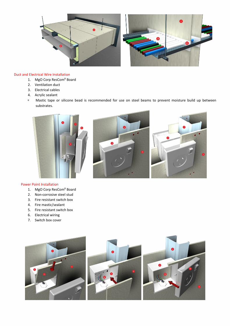
Duct and Electrical Wire Installation
1. MgO Corp ResComR Board
2. Ventilation duct
3. Electrical cables
4. Acrylic sealant
∗ Mastic tape or silicone bead is recommended for use on steel beams to prevent moisture build up between
substrates.
Power Point Installation
1. MgO Corp ResComR Board
2. Non-corrosive steel stud
3. Fire resistant switch box
4. Fire mastic/sealant
5. Fire resistant switch box
6. Electrical wiring
7. Switch box cover

Fire Collar Installation
6. MgO Corp ResComR Board
7. Wall collar
8. Plastic pipe
9. Concrete slab or wall
10. Collar
Duct and Electrical Wire Installation
5. MgO Corp ResComR Board
6. Ventilation duct
7. Electrical cables
8. Acrylic sealant
∗ Mastic tape or silicone bead is recommended for use on steel beams to prevent moisture build up between
substrates.

Magnesium Oxide Board Corporation Pty Ltd
8/175 Ocean Drive, Twin Waters, Queensland
4564
ABN: 47151952742
Phone: +61 7 5450 7314
Fax: +61 7 5450 7051
Email: [email protected]
Web: www.mgoboard.com.au