fire rated systems - gib®...fire rated ceiling systems 71–74 universal ceiling systems 71–74...
TRANSCRIPT

Fire Rated SystemsSpecification and installation manual
CBI5113
OCTOBER 2018
NATIONAL SUPPORT
VISIT: Winstone Wallboards Limited
37 Felix Street, Penrose,
Auckland 1061, New Zealand
POST: PO Box 12 256, Penrose,
Auckland 1642, New Zealand
PHONE: +64 9 633 0100
FAX: +64 9 633 0101
Free fax: 0800 229 222
EMAIL: [email protected]
WEB: gib.co.nz
GIB® HELPLINE
0800 100 442
Appraisal No. 289 [2018]
An effective fire design not only addresses life safety, but also considers personal property protection and ongoing business viability after exposure to a possible fire. The New Zealand Building Code requirements for fire safety represent the minimum allowable standard of protection to ensure the health and life safety of building occupants. The building code provisions aim to protect adjacent property but not the building itself, nor its contents, and often fall short of what people and businesses expect and find acceptable.
Most specifications in this technical literature are similar to those published in ‘GIB® Fire Rated Systems, October 2012’ with the following additions:
NEW PRODUCT— GIB Fire Soundseal®
— GIB® Grabber® Drill Point Fine Thread screws NEW SYSTEMS— GBSm 10 — Smoke separation wall— GBTL 30c— GBUW 60/GBUC 60 — revised— GBUW 180— GBS 90b/GBS 60b— GBS 120b— GIB® Panel Shaft
OTHER ADDITIONS— NLB steel stud height guidance— ‘Top-down’ fire exposure design guidance— Metal components used within suspended ceiling
grid systems— Clarifications to junction details including
deflection heads
3GIB® FIRE RATED SYSTEMSGIB® HELPLINE 0800 100 442 OR GIB.CO.NZ FOR MORE INFOOCTOBER 2018

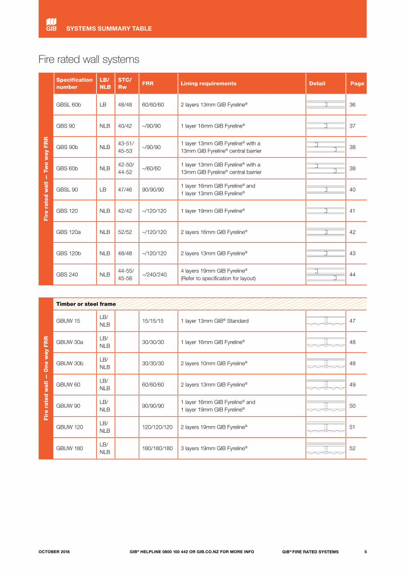
Fire rated wall systems
Fir
e r
ate
d w
all
— T
wo w
ay F
RR
Specification number
LB/NLB
STC/Rw
FRR Lining requirements Detail Page
Smoke separation - timber or steel frame
GBSm 10 LB 10/10/10 1 layer 10mm GIB® plasterboard 21
Timber frame
GBTL 30 LB 33/34 30/30/30 1 layer 10mm GIB Fyreline® 22
GBTL 30b LB 35/35 30/30/30 1 layer 13mm GIB® Standard 23
GBTL 30c LB 33/34 30/30/30 1 layer 10mm GIB® Standard 23
GBTL 60 LB 36/36 60/60/60 1 layer 13mm GIB Fyreline® 24
GBTL 60b LB 44/43 60/60/60 2 layers 10mm GIB Fyreline® 25
GBTL 90 LB 36/37 90/90/90 1 layer 16mm GIB Fyreline® 26
GBT 120a NLB 46/45 –/120/120 2 layers 13mm GIB Fyreline® 27
GBT 120b NLB 33/37 –/120/120 1 layer 19mm GIB Fyreline® 28
GBTL 120 LB 45/45 120/120/120 2 layers 16mm GIB Fyreline® 29
GBT 180 NLB 45/45 –/180/180 2 layers 16mm GIB Fyreline® 30
GBT 240 NLB44-55/ 45-56
–/240/2404 layers 19mm GIB Fyreline® (Refer to specification for layout)
44
Steel frame
GBSL 15 LB 35/35 15/15/15 1 layer 13mm GIB® Standard 32
GBS 30 NLB 35/35 –/30/30 1 layer 13mm GIB® Standard 33
GBSL 30a LB 40/40 30/30/30 1 layer 16mm GIB Fyreline® 34
GBSL 30b LB 45/45 30/30/30 2 layers 10mm GIB Fyreline® 34
GBS 60 NLB 37/37 –/60/60 1 layer 13mm GIB Fyreline® 35
GBSL 60a LB 40/40 60/60/60 1 layer 19mm GIB Fyreline® 36
4 GIB® FIRE RATED SYSTEMS GIB® HELPLINE 0800 100 442 OR GIB.CO.NZ FOR MORE INFO OCTOBER 2018
SYSTEMS SUMMARY TABLE
Fir
e r
ate
d w
all
— T
wo w
ay F
RR
Specification number
LB/NLB
STC/Rw
FRR Lining requirements Detail Page
GBSL 60b LB 48/48 60/60/60 2 layers 13mm GIB Fyreline® 36
GBS 90 NLB 40/42 –/90/90 1 layer 16mm GIB Fyreline® 37
GBS 90b NLB43-51/ 45-53
–/90/901 layer 13mm GIB Fyreline® with a 13mm GIB Fyreline® central barrier
38
GBS 60b NLB42-50/ 44-52
–/60/601 layer 13mm GIB Fyreline® with a 13mm GIB Fyreline® central barrier
38
GBSL 90 LB 47/46 90/90/901 layer 16mm GIB Fyreline® and 1 layer 13mm GIB Fyreline®
40
GBS 120 NLB 42/42 –/120/120 1 layer 19mm GIB Fyreline® 41
GBS 120a NLB 52/52 –/120/120 2 layers 16mm GIB Fyreline® 42
GBS 120b NLB 48/48 –/120/120 2 layers 13mm GIB Fyreline® 43
GBS 240 NLB44-55/ 45-56
–/240/2404 layers 19mm GIB Fyreline® (Refer to specification for layout)
44
Fir
e r
ate
d w
all
— O
ne w
ay F
RR
Timber or steel frame
GBUW 15LB/NLB
15/15/15 1 layer 13mm GIB® Standard 47
GBUW 30aLB/NLB
30/30/30 1 layer 16mm GIB Fyreline® 48
GBUW 30bLB/NLB
30/30/30 2 layers 10mm GIB Fyreline® 48
GBUW 60LB/NLB
60/60/60 2 layers 13mm GIB Fyreline® 49
GBUW 90LB/NLB
90/90/901 layer 16mm GIB Fyreline® and 1 layer 19mm GIB Fyreline®
50
GBUW 120LB/NLB
120/120/120 2 layers 19mm GIB Fyreline® 51
GBUW 180LB/NLB
180/180/180 3 layers 19mm GIB Fyreline® 52
Fire rated wall systems
5GIB® FIRE RATED SYSTEMSGIB® HELPLINE 0800 100 442 OR GIB.CO.NZ FOR MORE INFOOCTOBER 2018
SYSTEMS SUMMARY TABLE

Fire rated floor/ceiling systems
Fir
e r
ate
d f
loor/
ceilin
g
Specification number
LB/NLB
STC/Rw
FRR IIC Lining requirements Page
Timber joist
GBFC 15 LB 38/38 15/15/15 31 1 layer 13mm GIB® Standard 54
GBFC 30 LB 39/40 30/30/30 32 1 layer 13mm GIB Fyreline® 56
GBFC 45 LB 39/40 45/45/45 32 1 layer 13mm GIB Fyreline® 56
GBFC 60 LB 39/40 60/60/60 32 1 layer 16mm GIB Fyreline® 58
GBFC 90 LB 41/41 90/90/90 34 2 layers 16mm GIB Fyreline® 60
Timber or steel joist
GBFC 120 LB 120/120/120 2 layers 19mm GIB Fyreline® 62
Composite joist
GBCJ 30 LB 39/40 30/30/30 32 1 layer 13mm GIB Fyreline® 63
GBCJ 45 LB 39/40 45/45/45 32 1 layer 13mm GIB Fyreline® 63
GBCJ 60 LB 39/39 60/60/60 32 1 layer 16mm GIB Fyreline® 64
Steel joist
GBSJ 30 LB 34/34 30/30/30 30 1 layer 13mm GIB Fyreline® 65
GBSJ 60 LB 39/39 60/60/60 32 1 layer 16mm GIB Fyreline® 66
Suspended grid
GBSC 30 LB 48/47 30/30/30 43 1 layer 13mm GIB Fyreline® (back blocked) 67
GBSC 60a LB 53/52 60/60/60 43 2 layers 13mm GIB Fyreline® 68
GBSC 60b LB 50/49 60/60/60 43 1 layer 16mm GIB Fyreline® 69
GBSC 90 LB 53/52 90/90/90 43 1 layer 13mm GIB Fyreline® and 1 layer 16mm GIB Fyreline® 70
6 GIB® FIRE RATED SYSTEMS GIB® HELPLINE 0800 100 442 OR GIB.CO.NZ FOR MORE INFO OCTOBER 2018
SYSTEMS SUMMARY TABLE

Fire rated ceiling systems
Fir
e r
ate
d c
eilin
g
Specification number
LB/NLB
STC/Rw
FRR Lining requirements Page
Timber or steel frame
GBUC 15LB/NLB
15/15/15 1 layer 13mm GIB Fyreline® 71
GBUC 30LB/NLB
30/30/30 1 layer 16mm GIB Fyreline® 72
GBUC 60LB/NLB
60/60/60 2 layers 13mm GIB Fyreline® 73
GBUC 90LB/NLB
90/90/90 2 layers 19mm GIB Fyreline® 74
GBUC 120LB/NLB
120/120/120 2 layers 19mm GIB Fyreline® 74
7GIB® FIRE RATED SYSTEMSGIB® HELPLINE 0800 100 442 OR GIB.CO.NZ FOR MORE INFOOCTOBER 2018
SYSTEMS SUMMARY TABLE
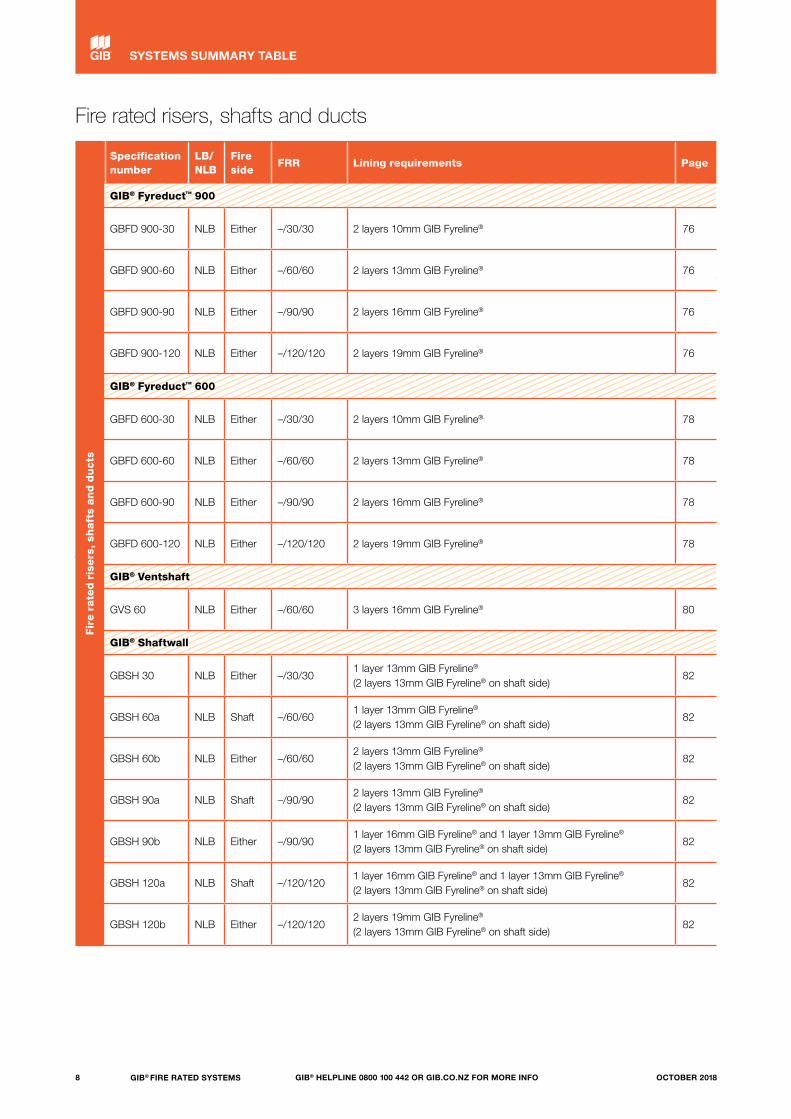
Fire rated risers, shafts and ducts
Fir
e r
ate
d r
isers
, sh
aft
s an
d d
ucts
Specification number
LB/NLB
Fire side
FRR Lining requirements Page
GIB® Fyreduct™ 900
GBFD 900-30 NLB Either –/30/30 2 layers 10mm GIB Fyreline® 76
GBFD 900-60 NLB Either –/60/60 2 layers 13mm GIB Fyreline® 76
GBFD 900-90 NLB Either –/90/90 2 layers 16mm GIB Fyreline® 76
GBFD 900-120 NLB Either –/120/120 2 layers 19mm GIB Fyreline® 76
GIB® Fyreduct™ 600
GBFD 600-30 NLB Either –/30/30 2 layers 10mm GIB Fyreline® 78
GBFD 600-60 NLB Either –/60/60 2 layers 13mm GIB Fyreline® 78
GBFD 600-90 NLB Either –/90/90 2 layers 16mm GIB Fyreline® 78
GBFD 600-120 NLB Either –/120/120 2 layers 19mm GIB Fyreline® 78
GIB® Ventshaft
GVS 60 NLB Either –/60/60 3 layers 16mm GIB Fyreline® 80
GIB® Shaftwall
GBSH 30 NLB Either –/30/301 layer 13mm GIB Fyreline® (2 layers 13mm GIB Fyreline® on shaft side)
82
GBSH 60a NLB Shaft –/60/601 layer 13mm GIB Fyreline® (2 layers 13mm GIB Fyreline® on shaft side)
82
GBSH 60b NLB Either –/60/602 layers 13mm GIB Fyreline® (2 layers 13mm GIB Fyreline® on shaft side)
82
GBSH 90a NLB Shaft –/90/902 layers 13mm GIB Fyreline® (2 layers 13mm GIB Fyreline® on shaft side)
82
GBSH 90b NLB Either –/90/901 layer 16mm GIB Fyreline® and 1 layer 13mm GIB Fyreline® (2 layers 13mm GIB Fyreline® on shaft side)
82
GBSH 120a NLB Shaft –/120/1201 layer 16mm GIB Fyreline® and 1 layer 13mm GIB Fyreline® (2 layers 13mm GIB Fyreline® on shaft side)
82
GBSH 120b NLB Either –/120/1202 layers 19mm GIB Fyreline® (2 layers 13mm GIB Fyreline® on shaft side)
82
8 GIB® FIRE RATED SYSTEMS GIB® HELPLINE 0800 100 442 OR GIB.CO.NZ FOR MORE INFO OCTOBER 2018
SYSTEMS SUMMARY TABLE
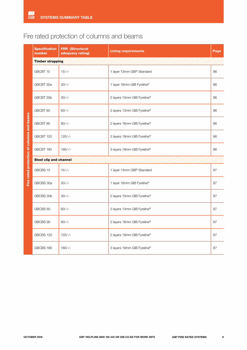
Fire rated protection of columns and beams
Fir
e r
ate
d p
rote
cti
on o
f colu
mn
s an
d b
eam
s
Specification number
FRR (Structural adequacy rating)
Lining requirements Page
Timber strapping
GBCBT 15 15/-/- 1 layer 13mm GIB® Standard 86
GBCBT 30a 30/-/- 1 layer 16mm GIB Fyreline® 86
GBCBT 30b 30/-/- 2 layers 10mm GIB Fyreline® 86
GBCBT 60 60/-/- 2 layers 13mm GIB Fyreline® 86
GBCBT 90 90/-/- 2 layers 16mm GIB Fyreline® 86
GBCBT 120 120/-/- 2 layers 19mm GIB Fyreline® 86
GBCBT 180 180/-/- 3 layers 19mm GIB Fyreline® 86
Steel clip and channel
GBCBS 15 15/-/- 1 layer 13mm GIB® Standard 87
GBCBS 30a 30/-/- 1 layer 16mm GIB Fyreline® 87
GBCBS 30b 30/-/- 2 layers 10mm GIB Fyreline® 87
GBCBS 60 60/-/- 2 layers 13mm GIB Fyreline® 87
GBCBS 90 90/-/- 2 layers 16mm GIB Fyreline® 87
GBCBS 120 120/-/- 2 layers 19mm GIB Fyreline® 87
GBCBS 180 180/-/- 3 layers 19mm GIB Fyreline® 87
9GIB® FIRE RATED SYSTEMSGIB® HELPLINE 0800 100 442 OR GIB.CO.NZ FOR MORE INFOOCTOBER 2018
SYSTEMS SUMMARY TABLE
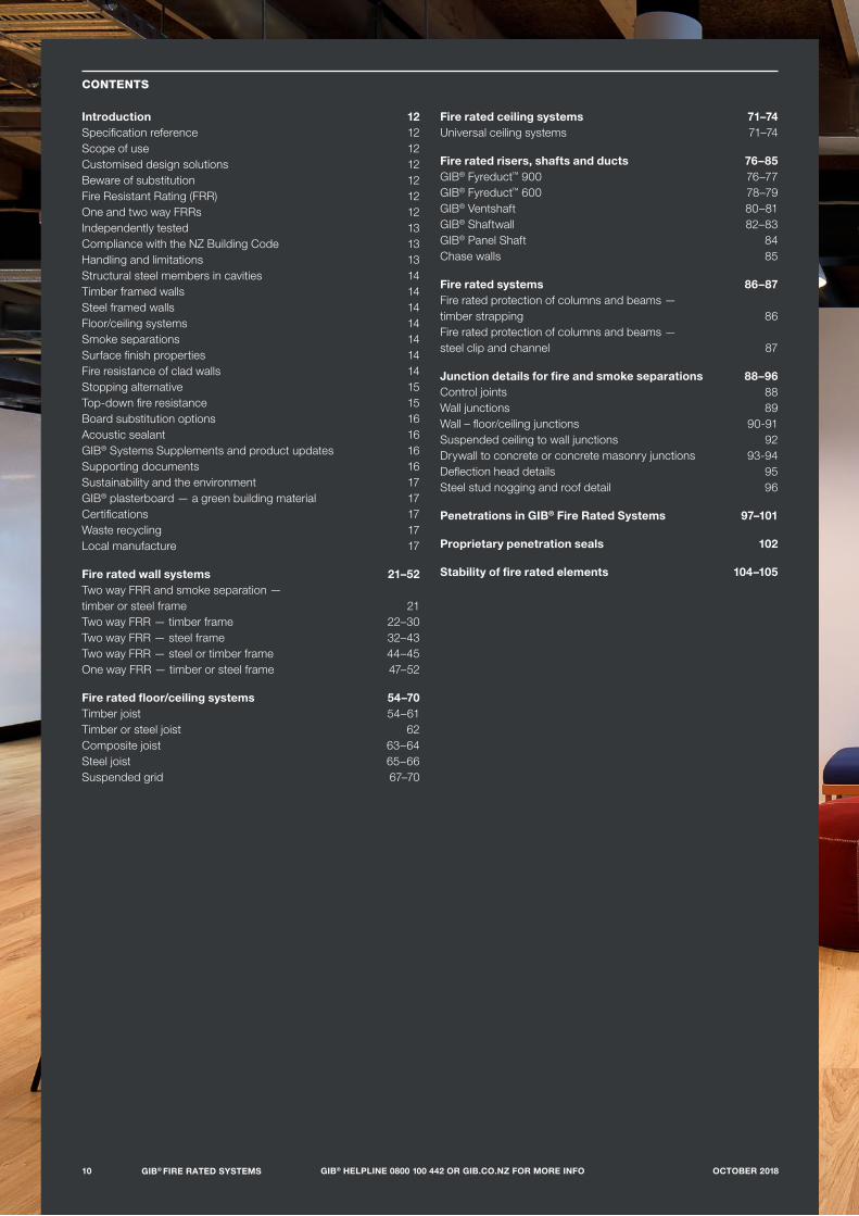
CONTENTS
Introduction 12Specification reference 12Scope of use 12Customised design solutions 12Beware of substitution 12Fire Resistant Rating (FRR) 12One and two way FRRs 12Independently tested 13Compliance with the NZ Building Code 13Handling and limitations 13Structural steel members in cavities 14Timber framed walls 14Steel framed walls 14Floor/ceiling systems 14Smoke separations 14Surface finish properties 14Fire resistance of clad walls 14Stopping alternative 15Top-down fire resistance 15Board substitution options 16Acoustic sealant 16GIB® Systems Supplements and product updates 16Supporting documents 16Sustainability and the environment 17GIB® plasterboard — a green building material 17Certifications 17Waste recycling 17Local manufacture 17
Fire rated wall systems 21–52Two way FRR and smoke separation — timber or steel frame 21Two way FRR — timber frame 22–30Two way FRR — steel frame 32–43Two way FRR — steel or timber frame 44–45One way FRR — timber or steel frame 47–52
Fire rated floor/ceiling systems 54–70Timber joist 54–61Timber or steel joist 62Composite joist 63–64Steel joist 65–66Suspended grid 67–70
Fire rated ceiling systems 71–74Universal ceiling systems 71–74
Fire rated risers, shafts and ducts 76–85GIB® Fyreduct™ 900 76–77GIB® Fyreduct™ 600 78–79GIB® Ventshaft 80–81GIB® Shaftwall 82–83GIB® Panel Shaft 84Chase walls 85
Fire rated systems 86–87Fire rated protection of columns and beams — timber strapping 86Fire rated protection of columns and beams — steel clip and channel 87
Junction details for fire and smoke separations 88–96Control joints 88Wall junctions 89Wall – floor/ceiling junctions 90-91Suspended ceiling to wall junctions 92Drywall to concrete or concrete masonry junctions 93-94Deflection head details 95Steel stud nogging and roof detail 96
Penetrations in GIB® Fire Rated Systems 97–101
Proprietary penetration seals 102
Stability of fire rated elements 104–105
10 GIB® FIRE RATED SYSTEMS GIB® HELPLINE 0800 100 442 OR GIB.CO.NZ FOR MORE INFO OCTOBER 2018

11GIB® FIRE RATED SYSTEMSGIB® HELPLINE 0800 100 442 OR GIB.CO.NZ FOR MORE INFOOCTOBER 2018
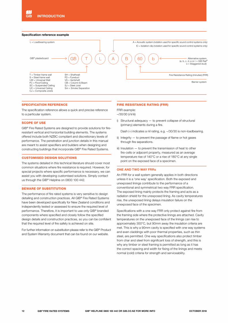
Specification reference example
GB T L A B 60 bGIB® plasterboard
T = Timber frame wall S = Steel frame wall UW = Universal Wall FC = Floor/Ceiling SC = Suspended Ceiling UC = Universal Ceiling CJ = Composite Joists
SH = Shaftwall FD = Fyreduct VS = Ventshaft CB = Column & Beam SJ = Steel Joist Sm = Smoke Separation
L = Loadbearing system
Fire Resistance Rating (minutes) (FRR)
A = Acoustic system (notation used for specific sound control systems only)
IC = Isolation clip (notation used for specific sound control systems only)
Alternative system (a, b, c, d, e or r = GIB Rail
s = Staggered stud)
Barrier system
SPECIFICATION REFERENCE
The specification reference allows a quick and precise reference to a particular system.
SCOPE OF USE
GIB® Fire Rated Systems are designed to provide solutions for fire- resistant vertical and horizontal building elements. The systems offered include both NZBC compliant and discretionary levels of performance. The penetration and junction details in this manual are meant to assist specifiers and builders when designing and constructing buildings that incorporate GIB® Fire Rated Systems.
CUSTOMISED DESIGN SOLUTIONS
The systems detailed in this technical literature should cover most common situations where fire resistance is required. However, for special projects where specific performance is necessary, we can assist you with developing customised solutions. Simply contact us through the GIB® Helpline on 0800 100 442.
BEWARE OF SUBSTITUTION
The performance of fire rated systems is very sensitive to design detailing and construction practices. All GIB® Fire Rated Systems have been developed specifically for New Zealand conditions and independently tested or assessed to ensure the required level of performance. Therefore, it is important to use only GIB® branded components where specified and closely follow the specified design details and construction practices, so you can be confident that the required level of fire safety is achieved on site.
For further information on substitution please refer to the GIB® Product and System Warranty document that can be found on our website.
FIRE RESISTANCE RATING (FRR)
FRR example: –/30/30 (i/ii/iii)
i) Structural adequacy — to prevent collapse of structural (primary) elements during a fire.
Dash (–) indicates a nil rating, e.g. –/30/30 is non-loadbearing.
ii) Integrity — to prevent the passage of flame or hot gases through fire separations.
iii) Insulation — to prevent the transmission of heat to other fire-cells or adjacent property, measured as an average temperature rise of 140°C or a rise of 180°C at any single point on the exposed face of a specimen.
ONE AND TWO WAY FRRs
An FRR for a wall system generally applies in both directions unless it is a ‘one way’ specification. Both the exposed and unexposed linings contribute to the performance of a conventional and symmetrical two way FRR specification. The exposed lining mainly protects the framing and acts as a radiation shield for the unexposed lining. As cavity temperatures rise, the unexposed lining delays insulation failure on the unexposed face of the specimen.
Specifications with a one way FRR only protect against fire from the framing side where the protective linings are attached. Cavity temperatures on the unexposed face of the linings can rise to approximately 300°C, but 90mm away the insulation criteria are met. This is why a 90mm cavity is specified with one way systems and even claddings with poor thermal properties, such as thin steel, are permitted. One way specifications also protect timber from char and steel from significant loss of strength, and this is why any timber or steel framing is permitted as long as it has the correct spacing and width for fixing of the linings and meets normal (cold) criteria for strength and serviceability.
®
12 GIB® FIRE RATED SYSTEMS GIB® HELPLINE 0800 100 442 OR GIB.CO.NZ FOR MORE INFO OCTOBER 2018
INTRODUCTION

INDEPENDENTLY TESTED
This document has been appraised by the Building Research Association of New Zealand (BRANZ), Appraisal No. 289 [2018] GIB® Fire Rated Systems, 2018.
The FRRs of specifications published in the document have been obtained by independent testing or assessment sourced from organisations with accredited quality assurance. It is of prime importance to comply with the details of design, construction and workmanship in this document.
GIB® plasterboard is manufactured to strict quality standards and formulations are uniform nationwide.
All GIB® branded accessory products are the subject of ongoing quality control to ensure consistency of supply.
To allow positive identification on site, GIB Fyreline® is printed on the board tapers and centreline and the face paper is coloured pink.
COMPLIANCE WITH THE NZ BUILDING CODE
NZBC Clause B2 — DurabilityUnder normal conditions of dry internal use GIB® Fire Rated Systems have a serviceable life in excess of 50 years and satisfy the requirements of NZBC Clause B2 — Durability.
NZBC Clauses C1–C6 — Protection from FireGIB® Fire Rated Systems can be used to provide passive fire protection in accordance with the requirements of NZBC Clauses C1–C6 — Protection from Fire.
NZBC Clause C6 — Structural StabilityIn order to satisfy the requirements of this clause, designers must ensure that fire rated elements are supported by elements having at least the same Fire Resistance Rating (FRR). Collapse of elements having a lesser FRR shall not cause the consequential collapse of elements required to have a higher FRR.
Within the context of fire resistance, there is a clear distinction between ‘structural adequacy’ and ‘stability’.
Structural adequacyStructural adequacy is the first number in the x/x/x FRR sequence and relates to the ability of a specimen to resist applied vertical loads during the standard test for fire resistance.
If a floor requires a column for vertical support, then the column must have a structural adequacy rating no less than the FRR of the floor or floor/ceiling system.
Similarly, a wall supporting a floor above requires a structural adequacy rating no less than the FRR of the floor. In this case simply selecting an FRR may not always be appropriate, such as when the wall is located entirely within a fire-cell and is not itself a fire separation. In a standard furnace test for fire resistance, a specimen is commonly exposed from one side only. If a wall located within a fire-cell is potentially exposed to fire from both sides simultaneously, ‘universal’ or ‘one way’ lining protection may need to be provided to both sides.
Lateral stabilityAlthough stability can have a wider meaning, in the context of fire resistance we suggest it is referred to as lateral stability, or the ability of a building element to resist horizontal forces. Provision of lateral stability, where required, is a matter of design and is not determined by standard fire resistance testing.
Lateral stability provisions are usually required for external fire rated walls of single-storey or the top floor of multi-level buildings where support is lost when an unprotected roof structure fails in a fire. In this case external walls are designed as cantilevers capable of resisting a nominal lateral force. A cantilever design might not be required for external walls designed to be pulled inwards by a collapsing roof structure.
If a wall separates fire-cells and the non-affected fire-cell continues to provide lateral support, specific lateral stability provisions are usually not required.
NZBC Clause G6 — Airborne and Impact SoundFor many specifications in the technical literature Sound Transmission Class (STC / Rw) and Impact Insulation Class (IIC) performances are given. For higher performances, including those required by NZBC Clause G6 – Airborne and Impact Sound, consult the current version of ‘GIB Noise Control® Systems’.
HANDLING AND LIMITATIONS
GIB® plasterboard must be stacked flat and protected from the weather.
GIB® plasterboard must be handled as a finishing material.
GIB® plasterboard linings must not be exposed to liquid water or be installed in situations where extended exposures to relative humidity above 90% can reasonably be expected.
Adhesive in GIB® Fire Rated Systems cannot be used as an alternative to specified mechanical fasteners.
In normal use, GIB® plasterboard must not be exposed to temperatures in excess of 52ºC for prolonged periods.
13GIB® FIRE RATED SYSTEMSGIB® HELPLINE 0800 100 442 OR GIB.CO.NZ FOR MORE INFOOCTOBER 2018
INTRODUCTION

STRUCTURAL STEEL MEMBERS IN CAVITIES
Structural steel members are sometimes located inside the cavity of a GIB® Fire Rated System, such as a column in a wall or beam in a floor/ceiling system. The FRR of a wall or floor/ceiling system applies across the entire element, from the exposed to the unexposed face. Temperatures inside the cavity can rise to a critical level for some steel members and it cannot be automatically assumed that a steel member achieves the structural adequacy rating of the cavity system within which it is contained. For guidance on the protection of structural steel members, refer to the columns and beams section of this document.
TIMBER FRAMED WALLS
Loadbearing (LB) and non-loadbearing (NLB) wallsConsult the current edition of NZS 3604 to determine framing dimensions and wall heights for LB and NLB walls. Beyond these limits, specific engineering design is required.
Framing spacing cannot be more and timber dimensions cannot be less than those specified for the relevant GIB® system.
STEEL FRAMED WALLS
Non-loadbearing (NLB) wallsWall heights greater than the specified limit for the relevant GIB® specification are the subject of specific design for serviceability and fire design criteria. Consult the framing supplier for serviceability criteria.
Loadbearing (LB) wallsThe solutions in this technical literature for loadbearing steel stud walls are conservatively based on limiting steel temperature. More accurate predictions can be made if the applied stud load (at the time of the fire) and stud capacity (at ambient temperature) are known, using the equation:
FRR (LB) = FRR (NLB) x (1 — fire load/capacity), where; — FRR (LB) is the calculated FRR of the LB wall — FRR (NLB) is the FRR of the NLB wall with equivalent linings— Fire load is the applied stud load at the time of the fire
(kN/stud)— Capacity is the stud capacity at ambient temperature
(kN/stud)
Example: A loadbearing steel frame has an ambient capacity of 12kN/stud and a fire design load of 4kN/stud. The linings are 13mm GIB Fyreline® installed in accordance with NLB specification GBS 60. Estimate the FRR of the equivalent LB system as follows: FRR (LB) = 60 x (1 – 4/12) = 60 x 2/3 = 40 minutes, or FRR (LB) = 40/40/40.
FLOOR/CEILING SYSTEMS
Floor/ceiling systems have generally been tested for a design load of 3kPa. For span tables consult the latest version of NZS 3604 or proprietary joists supplier information.
Flooring shall be nominal 20mm oriented strand board, or 20mm particle board complying with AS/NZS 1860 Part 1:2017 Particleboard flooring — Specifications, or minimum 17mm plywood manufactured to AS/NZS 2269 Part 0:2012 Plywood — Structural — Specifications. Existing tight tongue and groove flooring in good condition and with a minimum thickness of 20mm is acceptable. Do not:
— decrease joist dimensions or increase joist or nog spacing from what has been specified
— substitute alternative type joist— exceed the maximum permissible design stress.
The protection of inclined stairs can be determined from floor/ceiling system specifications, provided the average depth of cavity is the same or greater.
SMOKE SEPARATIONS
Timber or steel stud wall lined on both faces with a minimum of 10mm GIB® plasterboard, and floor/ceiling systems lined with a minimum of 13mm GIB® plasterboard, will meet the requirement for an FRR of at least 10/10/– as required for a Smoke Separation. Lining installation stopping and finishing must be in accordance with the requirements as published in the GIB® Site Guide. Any remaining perimeter gaps greater than 0.5mm must be sealed to inhibit the passage of smoke.
SURFACE FINISH PROPERTIES
All paper-faced GIB® plasterboard sheet materials have been tested in accordance with ISO 5660 Reaction to Fire Tests — heat release, smoke production and mass loss rate Parts 1 and 2 and achieve a Group 1-S classification.
This classification applies to the plasterboard product without paint or wallpaper finish. The supplier or manufacturer of any selected surface finish must be contacted for their particular product classification when applied over a relevant substrate.
FIRE RESISTANCE OF CLAD WALLS
GIB® plasterboard installed on the external face of a frame must be protected from the weather during installation and in-service. The FRR of the GIB® System is unaffected by the cladding. Exterior cladding over the GIB® plasterboard must comply with:
— NZBC Clauses C1–6 with respect to exterior surface finishes — NZBC E2/AS1, and be installed over a flexible wall underlay
and drained cavity.
Where GIB® Fire Rated Systems are clad with any of the following materials, sheet joints and screw heads may be left unstopped:
— Timber or wood-based products — Flat or profiled steel— Fibre cement sheets or boards — Exterior insulation and finish systems (EIFS).
14 GIB® FIRE RATED SYSTEMS GIB® HELPLINE 0800 100 442 OR GIB.CO.NZ FOR MORE INFO OCTOBER 2018
INTRODUCTION

STOPPING ALTERNATIVE
As an alternative to plaster stopping, sheet joints (such as in ceiling voids) can be covered with a minimum 150mm-wide strip of GIB® plasterboard, centrally placed over the sheet joint, and screw fixed to the underlying framing at no more than 300mm centres.
TOP-DOWN FIRE RESISTANCE
The New Zealand Building Code documents require floors to be rated from the underside, based on the FRR of the fire-cell below. Although often ignored, potential top-down exposure is sometimes a consequence of building design and layout.
An FRR is by definition the result against a standard furnace test, and furnaces are not designed for top-down exposure. A standard test furnace is placed vertically for wall testing or rotated horizontally for a floor or ceiling specimen. Turning the furnace upside-down to expose an element from above is not practical. Turning the specimen upside-down does not fairly characterise gravity effects and would not be representative of actual construction.
The performance of top-down fire resistance can be assessed by considering wall and floor/ceiling test results. For a given FRR, the performance specification for ceiling linings is generally higher than for walls. Compare, for example, wall specification GBTL 60 (13mm GIB Fyreline® each side of timber studs) with specification GBFC 60 (16mm GIB Fyreline® on timber joists).
Because gravity acts more severely on ceiling linings, a higher performance lining is usually required. However, when installed on top, gravity assists by holding linings on a floor or floor framing.
Non-loadbearing floor/ceiling A top-down or two way FRR can be created by placing the corresponding wall lining on top of the framing and the relevant ceiling lining below. Figure 1 shows the solution using a 60-minute example.
Loadbearing floor/ceiling When it is desirable to provide a floor with loadbearing capability, the solution is to first install structural sheet flooring, which in turn is protected against top-down exposure with the corresponding GIB Fyreline® ceiling lining and a thin wear layer such as mdf, carpet or flooring vinyl (depending on intended use). This is illustrated in Figure 2.
For project-specific advice and further details, please contact our GIB® Helpline on 0800 100 442.
FIGURE 1 — 60-MINUTE NLB TOP-DOWN FRR
FIGURE 2 — 60-MINUTE LB TOP-DOWN FRR
GBTL 60 lining, 13mm GIB Fyreline®
GBFC 60 lining, 16mm GIB Fyreline®Thin wear layer
GBFC 60 lining, 16mm GIB Fyreline®
GBFC 60 lining, 16mm GIB Fyreline®Structural flooring
15GIB® FIRE RATED SYSTEMSGIB® HELPLINE 0800 100 442 OR GIB.CO.NZ FOR MORE INFOOCTOBER 2018
INTRODUCTION
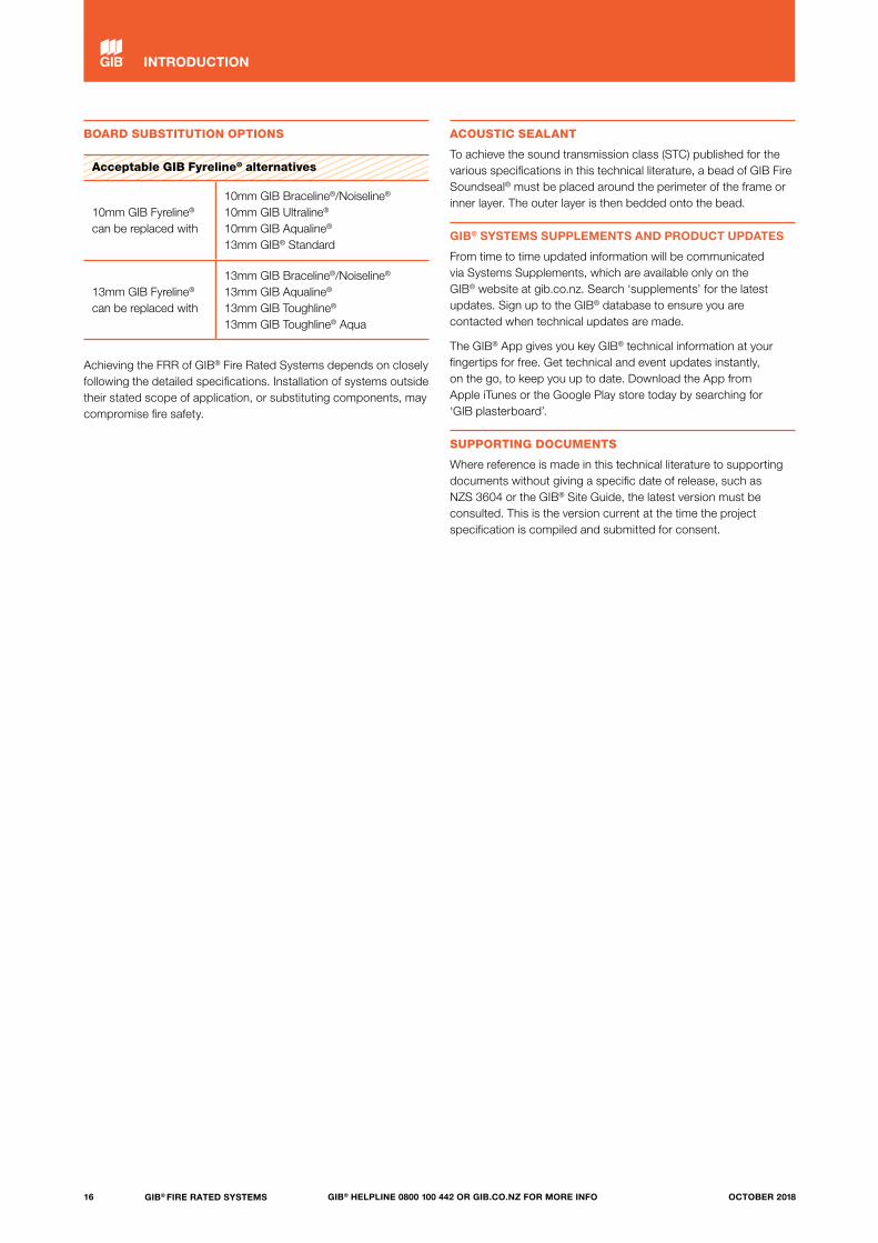
BOARD SUBSTITUTION OPTIONS
Acceptable GIB Fyreline® alternatives
10mm GIB Fyreline® can be replaced with
10mm GIB Braceline®/Noiseline®
10mm GIB Ultraline®
10mm GIB Aqualine®
13mm GIB® Standard
13mm GIB Fyreline® can be replaced with
13mm GIB Braceline®/Noiseline®
13mm GIB Aqualine®
13mm GIB Toughline®
13mm GIB Toughline® Aqua
Achieving the FRR of GIB® Fire Rated Systems depends on closely following the detailed specifications. Installation of systems outside their stated scope of application, or substituting components, may compromise fire safety.
ACOUSTIC SEALANT
To achieve the sound transmission class (STC) published for the various specifications in this technical literature, a bead of GIB Fire Soundseal® must be placed around the perimeter of the frame or inner layer. The outer layer is then bedded onto the bead.
GIB® SYSTEMS SUPPLEMENTS AND PRODUCT UPDATES
From time to time updated information will be communicated via Systems Supplements, which are available only on the GIB® website at gib.co.nz. Search ‘supplements’ for the latest updates. Sign up to the GIB® database to ensure you are contacted when technical updates are made.
The GIB® App gives you key GIB® technical information at your fingertips for free. Get technical and event updates instantly, on the go, to keep you up to date. Download the App from Apple iTunes or the Google Play store today by searching for ‘GIB plasterboard’.
SUPPORTING DOCUMENTS
Where reference is made in this technical literature to supporting documents without giving a specific date of release, such as NZS 3604 or the GIB® Site Guide, the latest version must be consulted. This is the version current at the time the project specification is compiled and submitted for consent.
16 GIB® FIRE RATED SYSTEMS GIB® HELPLINE 0800 100 442 OR GIB.CO.NZ FOR MORE INFO OCTOBER 2018
INTRODUCTION
SUSTAINABILITY AND THE ENVIRONMENT
Winstone Wallboards is committed to a holistic view of sustainability: environmental, social and economic.
— We manufacture products that are good for the environment. — We actively consider the full life cycle of our products and
support recycling initiatives both from our manufacturing and general construction waste.
— We innovate systems and solutions that keep people safe and protected in buildings.
— We support jobs and growth within our communities.
GIB® PLASTERBOARD — A GREEN BUILDING MATERIAL
GIB® plasterboard is a sustainable, non-toxic, compostable and infinitely recyclable product made from natural gypsum and 100% recycled paper. GIB® plasterboards do not use fly ash, a derivative of coal extraction, as a bulk filler* in place of naturally occurring gypsum. Due to this, unlike many imported alternatives, a range of GIB® plasterboards are considered Red List Free, certified through Declare.
*Note: 10mm GIB Aqualine® board uses less than 0.7% fly ash as a processing agent, not as a bulk filler.
CERTIFICATIONS
Declare Winstone Wallboards has Declare certification for a range of our plasterboards. Considered one of the most advanced sustainability certifications in the built environment, Declare is like a nutritional label for building products, offering specifiers, contractors and building users insight into the ingredients used in the manufacture of building products.
Global Greentag A range of GIB® plasterboards have also achieved Global Greentag certification, one of the world’s most robust, trusted and widely recognised eco-labels.
Environmental Product Declaration (EPD) Winstone Wallboards has been the first and only plasterboard manufacturer in Australasia to publish an Environmental Product Declaration (EPD). The EPD quantifies the environmental performance of GIB® plasterboard including its carbon footprint, embodied energy and other environmental data. Projects utilising GIB® plasterboard will qualify for full Green Star points due to Winstone Wallboards holding an EPD for six or more products. The EPD for GIB® plasterboard is available on the GIB® website. Visit gib.co.nz to download these certifications.
WASTE RECYCLING
Winstone Wallboards works closely with local waste companies on initiatives to recycle plasterboard waste. Green Gorilla has introduced a plasterboard recycling service in Auckland. Plasterboard is collected separately from general building and construction waste, the waste volumes and tonnages are recorded and reported per project for builders and their customers, which allow plasterboard recovery statistics to be provided as part of total site landfill diversion and environmental reporting for Green Star and Homestar accreditation. In Christchurch, plasterboard manufacturing waste is processed with offcuts shredded and screened to return it to gypsum form. The recycled gypsum is supplied as a soil conditioner to farmers, orchards and vineyards.
LOCAL MANUFACTURE
GIB® plasterboard and compounds are manufactured in New Zealand*. We have complete oversight of our factory conditions and the teams who work in our manufacturing plants. Our decision to manufacture locally supports local jobs and directly supports the country’s economy.
*Note: GIB Barrierline® plasterboard is manufactured to Winstone Wallboards’ specific specification from a reputable overseas manufacturer.
17GIB® FIRE RATED SYSTEMSGIB® HELPLINE 0800 100 442 OR GIB.CO.NZ FOR MORE INFOOCTOBER 2018
INTRODUCTION
18 GIB® FIRE RATED SYSTEMS GIB® HELPLINE 0800 100 442 OR GIB.CO.NZ FOR MORE INFO OCTOBER 2018

19GIB® FIRE RATED SYSTEMSGIB® HELPLINE 0800 100 442 OR GIB.CO.NZ FOR MORE INFOOCTOBER 2018

20 GIB® FIRE RATED SYSTEMS GIB® HELPLINE 0800 100 442 OR GIB.CO.NZ FOR MORE INFO OCTOBER 2018
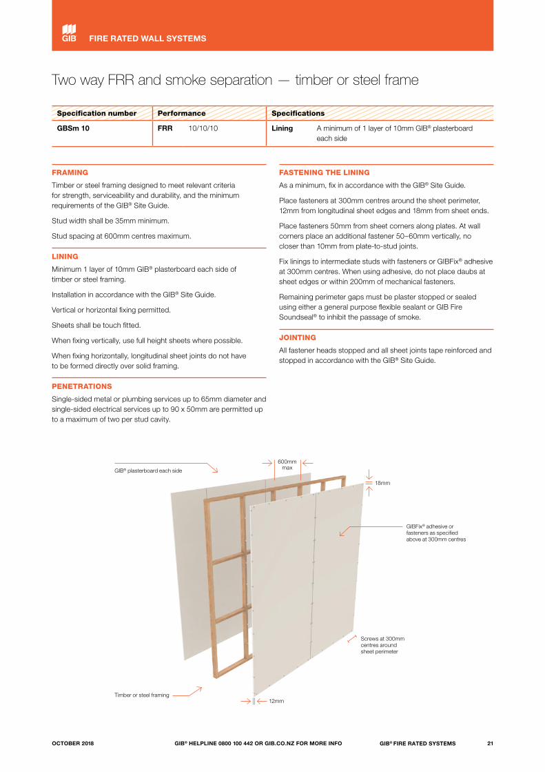
Two way FRR and smoke separation — timber or steel frame
Specification number Performance Specifications
GBSm 10 FRR 10/10/10 Lining A minimum of 1 layer of 10mm GIB® plasterboard each side
FRAMING
Timber or steel framing designed to meet relevant criteria for strength, serviceability and durability, and the minimum requirements of the GIB® Site Guide.
Stud width shall be 35mm minimum.
Stud spacing at 600mm centres maximum.
LINING
Minimum 1 layer of 10mm GIB® plasterboard each side of timber or steel framing.
Installation in accordance with the GIB® Site Guide.
Vertical or horizontal fixing permitted.
Sheets shall be touch fitted.
When fixing vertically, use full height sheets where possible.
When fixing horizontally, longitudinal sheet joints do not have to be formed directly over solid framing.
PENETRATIONS
Single-sided metal or plumbing services up to 65mm diameter and single-sided electrical services up to 90 x 50mm are permitted up to a maximum of two per stud cavity.
FASTENING THE LINING
As a minimum, fix in accordance with the GIB® Site Guide.
Place fasteners at 300mm centres around the sheet perimeter, 12mm from longitudinal sheet edges and 18mm from sheet ends.
Place fasteners 50mm from sheet corners along plates. At wall corners place an additional fastener 50–60mm vertically, no closer than 10mm from plate-to-stud joints.
Fix linings to intermediate studs with fasteners or GIBFix® adhesive at 300mm centres. When using adhesive, do not place daubs at sheet edges or within 200mm of mechanical fasteners.
Remaining perimeter gaps must be plaster stopped or sealed using either a general purpose flexible sealant or GIB Fire Soundseal® to inhibit the passage of smoke.
JOINTING
All fastener heads stopped and all sheet joints tape reinforced and stopped in accordance with the GIB® Site Guide.
GIB® plasterboard each side
Timber or steel framing
GIBFix® adhesive or fasteners as specified above at 300mm centres
600mm max
12mm
18mm
Screws at 300mm centres around sheet perimeter
21GIB® FIRE RATED SYSTEMSGIB® HELPLINE 0800 100 442 OR GIB.CO.NZ FOR MORE INFOOCTOBER 2018
FIRE RATED WALL SYSTEMS
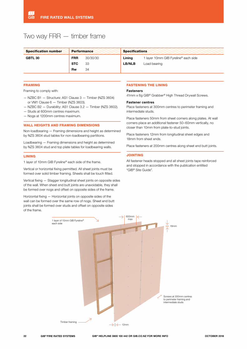
Two way FRR — timber frame
Specification number Performance Specifications
GBTL 30 FRR
STC
Rw
30/30/30
33
34
Lining
LB/NLB
1 layer 10mm GIB Fyreline® each side
Load bearing
FRAMING
Framing to comply with:
— NZBC B1 — Structure: AS1 Clause 3 — Timber (NZS 3604) or VM1 Clause 6 — Timber (NZS 3603).
— NZBC B2 — Durability: AS1 Clause 3.2 — Timber (NZS 3602).— Studs at 600mm centres maximum.— Nogs at 1200mm centres maximum.
WALL HEIGHTS AND FRAMING DIMENSIONS
Non-loadbearing — Framing dimensions and height as determined by NZS 3604 stud tables for non-loadbearing partitions.
Loadbearing — Framing dimensions and height as determined by NZS 3604 stud and top plate tables for loadbearing walls.
LINING
1 layer of 10mm GIB Fyreline® each side of the frame.
Vertical or horizontal fixing permitted. All sheet joints must be formed over solid timber framing. Sheets shall be touch fitted.
Vertical fixing — Stagger longitudinal sheet joints on opposite sides of the wall. When sheet end butt joints are unavoidable, they shall be formed over nogs and offset on opposite sides of the frame.
Horizontal fixing — Horizontal joints on opposite sides of the wall can be formed over the same row of nogs. Sheet end butt joints shall be formed over studs and offset on opposite sides of the frame.
FASTENING THE LINING
Fasteners 41mm x 6g GIB® Grabber® High Thread Drywall Screws.
Fastener centres Place fasteners at 300mm centres to perimeter framing and intermediate studs.
Place fasteners 50mm from sheet corners along plates. At wall corners place an additional fastener 50–60mm vertically, no closer than 10mm from plate-to-stud joints.
Place fasteners 12mm from longitudinal sheet edges and 18mm from sheet ends.
Place fasteners at 200mm centres along sheet end butt joints.
JOINTING
All fastener heads stopped and all sheet joints tape reinforced and stopped in accordance with the publication entitled “GIB® Site Guide”.
1 layer of 10mm GIB Fyreline® each side
Timber framing
600mm max
12mm
18mm
Screws at 300mm centres to perimeter framing and intermediate studs
22 GIB® FIRE RATED SYSTEMS GIB® HELPLINE 0800 100 442 OR GIB.CO.NZ FOR MORE INFO OCTOBER 2018
FIRE RATED WALL SYSTEMS
Two way FRR — timber frame
Specification number Performance Specifications
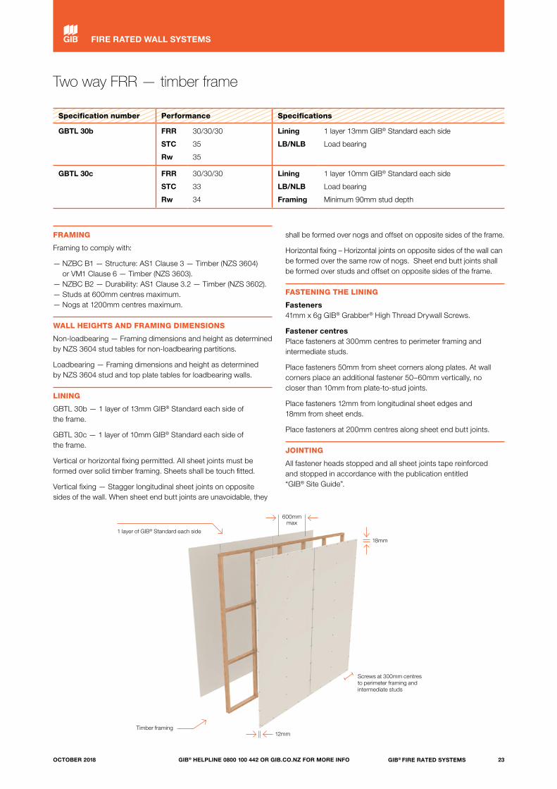
GBTL 30b FRR
STC
Rw
30/30/30
35
35
Lining
LB/NLB
1 layer 13mm GIB® Standard each side
Load bearing
GBTL 30c FRR
STC
Rw
30/30/30
33
34
Lining
LB/NLB
Framing
1 layer 10mm GIB® Standard each side
Load bearing
Minimum 90mm stud depth
FRAMING
Framing to comply with:
— NZBC B1 — Structure: AS1 Clause 3 — Timber (NZS 3604) or VM1 Clause 6 — Timber (NZS 3603).
— NZBC B2 — Durability: AS1 Clause 3.2 — Timber (NZS 3602).— Studs at 600mm centres maximum.— Nogs at 1200mm centres maximum.
WALL HEIGHTS AND FRAMING DIMENSIONS
Non-loadbearing — Framing dimensions and height as determined by NZS 3604 stud tables for non-loadbearing partitions.
Loadbearing — Framing dimensions and height as determined by NZS 3604 stud and top plate tables for loadbearing walls.
LINING
GBTL 30b — 1 layer of 13mm GIB® Standard each side of the frame.
GBTL 30c — 1 layer of 10mm GIB® Standard each side of the frame.
Vertical or horizontal fixing permitted. All sheet joints must be formed over solid timber framing. Sheets shall be touch fitted.
Vertical fixing — Stagger longitudinal sheet joints on opposite sides of the wall. When sheet end butt joints are unavoidable, they
shall be formed over nogs and offset on opposite sides of the frame.
Horizontal fixing – Horizontal joints on opposite sides of the wall can be formed over the same row of nogs. Sheet end butt joints shall be formed over studs and offset on opposite sides of the frame.
FASTENING THE LINING
Fasteners 41mm x 6g GIB® Grabber® High Thread Drywall Screws.
Fastener centres Place fasteners at 300mm centres to perimeter framing and intermediate studs.
Place fasteners 50mm from sheet corners along plates. At wall corners place an additional fastener 50–60mm vertically, no closer than 10mm from plate-to-stud joints.
Place fasteners 12mm from longitudinal sheet edges and 18mm from sheet ends.
Place fasteners at 200mm centres along sheet end butt joints.
JOINTING
All fastener heads stopped and all sheet joints tape reinforced and stopped in accordance with the publication entitled “GIB® Site Guide”.
1 layer of GIB® Standard each side
Timber framing12mm
Screws at 300mm centres to perimeter framing and intermediate studs
600mm max
18mm
23GIB® FIRE RATED SYSTEMSGIB® HELPLINE 0800 100 442 OR GIB.CO.NZ FOR MORE INFOOCTOBER 2018
FIRE RATED WALL SYSTEMS

Two way FRR — timber frame
Specification number Performance Specifications
GBTL 60 FRR
STC
Rw
60/60/60
36
36
Lining
LB/NLB
1 layer 13mm GIB Fyreline® each side
Load bearing
FRAMING
Framing to comply with:
— NZBC B1 — Structure: AS1 Clause 3 — Timber (NZS 3604) or VM1 Clause 6 — Timber (NZS 3603).
— NZBC B2 — Durability: AS1 Clause 3.2 — Timber (NZS 3602).— Studs at 600mm centres maximum.— Nogs at 1200mm centres maximum.
WALL HEIGHTS AND FRAMING DIMENSIONS
Non-loadbearing — Framing dimensions and height as determined by NZS 3604 stud tables for non-loadbearing partitions.
Loadbearing — Framing dimensions and height as determined by NZS 3604 stud and top plate tables for loadbearing walls.
LINING
1 layer of 13mm GIB Fyreline® each side of the frame.
Vertical or horizontal fixing permitted. All sheet joints must be formed over solid timber framing. Sheets shall be touch fitted.
Vertical fixing — Stagger longitudinal sheet joints on opposite sides of the wall. When sheet end butt joints are unavoidable, they shall be formed over nogs and offset on opposite sides of the frame.
Horizontal fixing — Horizontal joints on opposite sides of the wall can be formed over the same row of nogs. Sheet end butt joints shall be formed over studs and offset on opposite sides of the frame.
FASTENING THE LINING
Fasteners 41mm x 6g GIB® Grabber® High Thread Drywall Screws.
Fastener centres Place fasteners at 300mm centres to perimeter framing and intermediate studs.
Place fasteners 50mm from sheet corners along plates. At wall corners place an additional fastener 50–60mm vertically, no closer than 10mm from plate-to-stud joints.
Place fasteners 12mm from longitudinal sheet edges and 18mm from sheet ends.
Place fasteners at 200mm centres along sheet end butt joints.
JOINTING
All fastener heads stopped and all sheet joints tape reinforced and stopped in accordance with the publication entitled “GIB® Site Guide”.
1 layer of 13mm GIB Fyreline® each side
12mm
18mm
Screws at 300mm centres to perimeter framing and intermediate studs
600mm max
Timber framing
24 GIB® FIRE RATED SYSTEMS GIB® HELPLINE 0800 100 442 OR GIB.CO.NZ FOR MORE INFO OCTOBER 2018
FIRE RATED WALL SYSTEMS
Two way FRR — timber frame
Specification number Performance Specifications
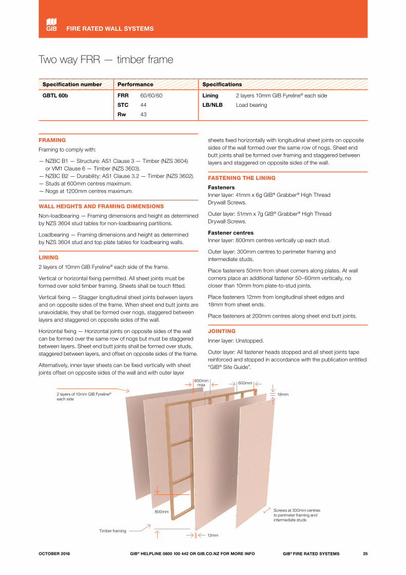
GBTL 60b FRR
STC
Rw
60/60/60
44
43
Lining
LB/NLB
2 layers 10mm GIB Fyreline® each side
Load bearing
FRAMING
Framing to comply with:
— NZBC B1 — Structure: AS1 Clause 3 — Timber (NZS 3604) or VM1 Clause 6 — Timber (NZS 3603).
— NZBC B2 — Durability: AS1 Clause 3.2 — Timber (NZS 3602).— Studs at 600mm centres maximum.— Nogs at 1200mm centres maximum.
WALL HEIGHTS AND FRAMING DIMENSIONS
Non-loadbearing — Framing dimensions and height as determined by NZS 3604 stud tables for non-loadbearing partitions.
Loadbearing — Framing dimensions and height as determined by NZS 3604 stud and top plate tables for loadbearing walls.
LINING
2 layers of 10mm GIB Fyreline® each side of the frame.
Vertical or horizontal fixing permitted. All sheet joints must be formed over solid timber framing. Sheets shall be touch fitted.
Vertical fixing — Stagger longitudinal sheet joints between layers and on opposite sides of the frame. When sheet end butt joints are unavoidable, they shall be formed over nogs, staggered between layers and staggered on opposite sides of the wall.
Horizontal fixing — Horizontal joints on opposite sides of the wall can be formed over the same row of nogs but must be staggered between layers. Sheet end butt joints shall be formed over studs, staggered between layers, and offset on opposite sides of the frame.
Alternatively, inner layer sheets can be fixed vertically with sheet joints offset on opposite sides of the wall and with outer layer
sheets fixed horizontally with longitudinal sheet joints on opposite sides of the wall formed over the same row of nogs. Sheet end butt joints shall be formed over framing and staggered between layers and staggered on opposite sides of the wall.
FASTENING THE LINING
Fasteners Inner layer: 41mm x 6g GIB® Grabber® High Thread Drywall Screws.
Outer layer: 51mm x 7g GIB® Grabber® High Thread Drywall Screws.
Fastener centres Inner layer: 800mm centres vertically up each stud.
Outer layer: 300mm centres to perimeter framing and intermediate studs.
Place fasteners 50mm from sheet corners along plates. At wall corners place an additional fastener 50–60mm vertically, no closer than 10mm from plate-to-stud joints.
Place fasteners 12mm from longitudinal sheet edges and 18mm from sheet ends.
Place fasteners at 200mm centres along sheet end butt joints.
JOINTING
Inner layer: Unstopped.
Outer layer: All fastener heads stopped and all sheet joints tape reinforced and stopped in accordance with the publication entitled “GIB® Site Guide”.
800mm
2 layers of 10mm GIB Fyreline® each side
Timber framing12mm
Screws at 300mm centres to perimeter framing and intermediate studs
600mm600mmmax
18mm
25GIB® FIRE RATED SYSTEMSGIB® HELPLINE 0800 100 442 OR GIB.CO.NZ FOR MORE INFOOCTOBER 2018
FIRE RATED WALL SYSTEMS

Two way FRR — timber frame
Specification number Performance Specifications
GBTL 90 FRR
STC
Rw
90/90/90
36
37
Lining
LB/NLB
1 layer 16mm GIB Fyreline® each side
Load bearing
FRAMING
Framing to comply with:
— NZBC B1 — Structure: AS1 Clause 3 — Timber (NZS 3604) or VM1 Clause 6 — Timber (NZS 3603).
— NZBC B2 — Durability: AS1 Clause 3.2 — Timber (NZS 3602).— Studs at 600mm centres maximum.— Nogs at 1200mm centres maximum.
WALL HEIGHTS AND FRAMING DIMENSIONS
Non-loadbearing — Framing dimensions and height as determined by NZS 3604 stud tables for non-loadbearing partitions.
Loadbearing — Framing dimensions and height as determined by NZS 3604 stud and top plate tables for loadbearing walls.
LINING
1 layer of 16mm GIB Fyreline® each side of the frame.
Vertical or horizontal fixing permitted. All sheet joints must be formed over solid timber framing. Sheets shall be touch fitted.
Vertical fixing — Stagger longitudinal sheet joints on opposite sides of the wall. When sheet end butt joints are unavoidable, they shall be formed over nogs and offset on opposite sides of the frame.
Horizontal fixing — Horizontal joints on opposite sides of the wall can be formed over the same row of nogs. Sheet end butt joints shall be formed over studs and offset on opposite sides of the frame.
FASTENING THE LINING
Fasteners 51mm x 7g GIB® Grabber® High Thread Drywall Screws.
Fastener centres Place fasteners at 300mm centres to perimeter framing and intermediate studs.
Place fasteners 50mm from sheet corners along plates. At wall corners place an additional fastener 50–60mm vertically, no closer than 10mm from plate-to-stud joints.
Place fasteners 12mm from longitudinal sheet edges and 18mm from sheet ends.
Place fasteners at 200mm centres along sheet end butt joints.
JOINTING
All fastener heads stopped and all sheet joints tape reinforced and stopped in accordance with the publication entitled “GIB® Site Guide”.
1 layer of 16mm GIB Fyreline® each side
18mm
Screws at 300mm centres to perimeter framing and intermediate studs
600mm max
12mmTimber framing
26 GIB® FIRE RATED SYSTEMS GIB® HELPLINE 0800 100 442 OR GIB.CO.NZ FOR MORE INFO OCTOBER 2018
FIRE RATED WALL SYSTEMS

Two way FRR — timber frame
Specification number Performance Specifications
GBT 120a FRR
STC
Rw
–/120/120
46
45
Lining
LB/NLB
2 layers 13mm GIB Fyreline® each side
Non load bearing
FRAMING
Framing to comply with:
— NZBC B1 — Structure: AS1 Clause 3 — Timber (NZS 3604) or VM1 Clause 6 — Timber (NZS 3603).
— NZBC B2 — Durability: AS1 Clause 3.2 — Timber (NZS 3602).— Studs at 600mm centres maximum.— Nogs at 800mm centres maximum.
WALL HEIGHTS AND FRAMING DIMENSIONS
Framing dimensions and height as determined by NZS 3604 stud tables for non-loadbearing walls.
LINING
2 layers of 13mm GIB Fyreline® each side of the frame.
Vertical fixing permitted only. All sheet joints must be formed over solid timber framing. Sheets shall be touch fitted.
Stagger longitudinal sheet joints between layers and on opposite sides of the frame. When sheet end butt joints are unavoidable, they shall be formed over nogs, staggered between layers and staggered on opposite sides of the wall.
FASTENING THE LINING
Fasteners Inner layer: 51mm x 7g GIB® Grabber® High Thread Drywall Screws.
Outer layer: 63mm x 8g GIB® Grabber® Self Tapping Drywall Screws.
Fastener centres Inner layer: 800mm centres vertically up each stud.
Outer layer: 300mm centres to perimeter framing and intermediate studs.
Place fasteners 50mm from sheet corners along plates. At wall corners place an additional fastener 50–60mm vertically, no closer than 10mm from plate-to-stud joints.
Place fasteners 12mm from longitudinal sheet edges and 18mm from sheet ends.
Place fasteners at 200mm centres along sheet end butt joints.
JOINTING
Inner layer: Unstopped.
Outer layer: All fastener heads stopped and all sheet joints tape reinforced and stopped in accordance with the publication entitled “GIB® Site Guide”.
800mmmax
2 layers of 13mm GIB Fyreline® each side
Timber framing12mm
Screws at 300mm centres to perimeter framing and intermediate studs
600mm max 600mm
18mm
800mm
27GIB® FIRE RATED SYSTEMSGIB® HELPLINE 0800 100 442 OR GIB.CO.NZ FOR MORE INFOOCTOBER 2018
FIRE RATED WALL SYSTEMS

Two way FRR — timber frame
Specification number Performance Specifications
GBT 120b FRR
STC
Rw
–/120/120
33
37
Lining
LB/NLB
1 layer 19mm GIB Fyreline® each side
Non load bearing
FRAMING
Framing to comply with:
— NZBC B1 — Structure: AS1 Clause 3 — Timber (NZS 3604) or VM1 Clause 6 — Timber (NZS 3603).
— NZBC B2 — Durability: AS1 Clause 3.2 — Timber (NZS 3602).— Studs at 600mm centres maximum.— Nogs at 1200mm centres maximum.
WALL HEIGHTS AND FRAMING DIMENSIONS
Framing dimensions and height as determined by NZS 3604 stud tables for non-loadbearing walls.
LINING
1 layer of 19mm GIB Fyreline® each side of the frame.
Vertical or horizontal fixing permitted. All sheet joints must be formed over solid timber framing. Sheets shall be touch fitted.
Vertical fixing — Stagger longitudinal sheet joints on opposite sides of the wall. When sheet end butt joints are unavoidable, they shall be formed over nogs and offset on opposite sides of the frame.
Horizontal fixing — Horizontal joints on opposite sides of the wall can be formed over the same row of nogs. Sheet end butt joints shall be formed over studs and offset on opposite sides of the frame.
FASTENING THE LINING
Fasteners 51mm x 7g GIB® Grabber® High Thread Drywall Screws.
Fastener centres Place fasteners at 300mm centres to perimeter framing and intermediate studs.
Place fasteners 50mm from sheet corners along plates. At wall corners place an additional fastener 50–60mm vertically, no closer than 10mm from plate-to-stud joints.
Place fasteners 12mm from longitudinal sheet edges and 18mm from sheet ends.
Place fasteners at 200mm centres along sheet end butt joints.
JOINTING
All fastener heads stopped and all sheet joints tape reinforced and stopped in accordance with the publication entitled “GIB® Site Guide”.
1 layer of 19mm GIB Fyreline® each side
18mm
Screws at 300mm centres to perimeter framing and intermediate studs
600mm max
12mmTimber framing
28 GIB® FIRE RATED SYSTEMS GIB® HELPLINE 0800 100 442 OR GIB.CO.NZ FOR MORE INFO OCTOBER 2018
FIRE RATED WALL SYSTEMS
Two way FRR — timber frame
Specification number Performance Specifications
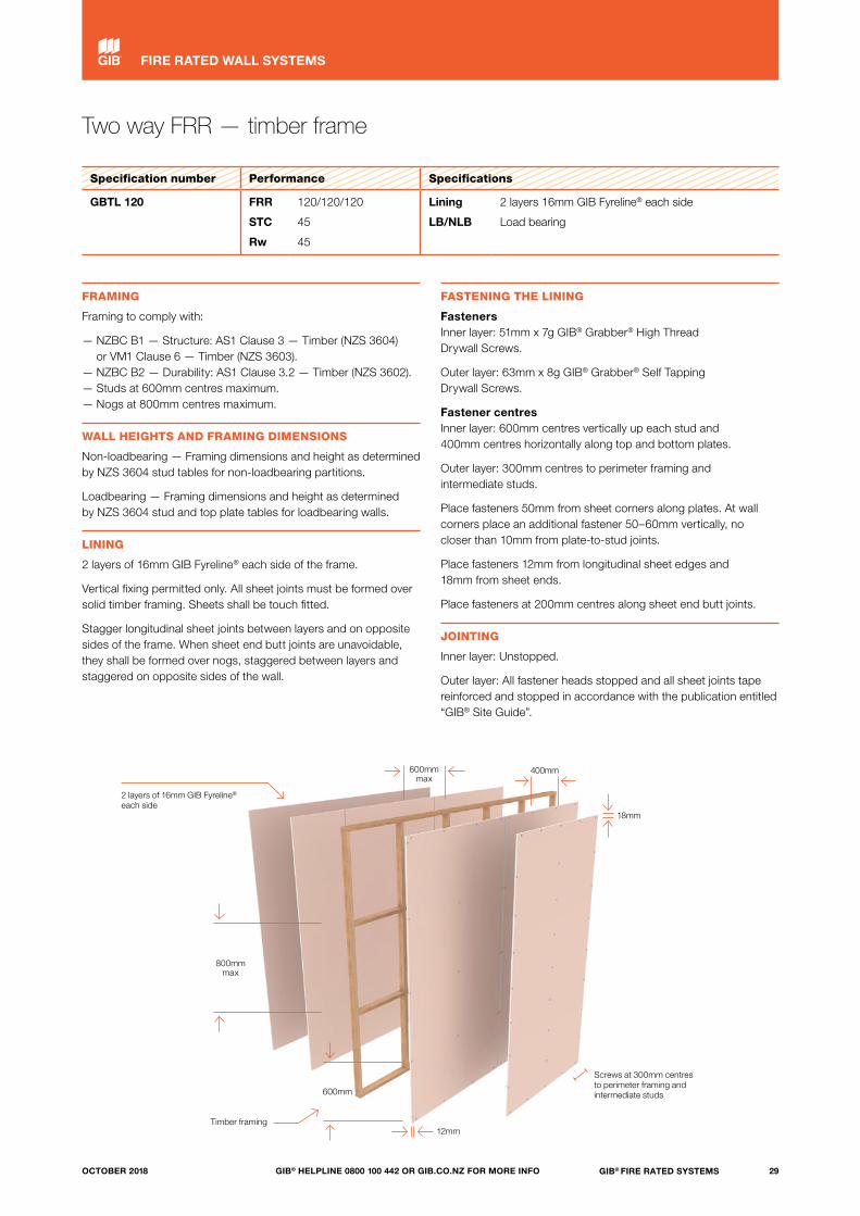
GBTL 120 FRR
STC
Rw
120/120/120
45
45
Lining
LB/NLB
2 layers 16mm GIB Fyreline® each side
Load bearing
FRAMING
Framing to comply with:
— NZBC B1 — Structure: AS1 Clause 3 — Timber (NZS 3604) or VM1 Clause 6 — Timber (NZS 3603).
— NZBC B2 — Durability: AS1 Clause 3.2 — Timber (NZS 3602).— Studs at 600mm centres maximum.— Nogs at 800mm centres maximum.
WALL HEIGHTS AND FRAMING DIMENSIONS
Non-loadbearing — Framing dimensions and height as determined by NZS 3604 stud tables for non-loadbearing partitions.
Loadbearing — Framing dimensions and height as determined by NZS 3604 stud and top plate tables for loadbearing walls.
LINING
2 layers of 16mm GIB Fyreline® each side of the frame.
Vertical fixing permitted only. All sheet joints must be formed over solid timber framing. Sheets shall be touch fitted.
Stagger longitudinal sheet joints between layers and on opposite sides of the frame. When sheet end butt joints are unavoidable, they shall be formed over nogs, staggered between layers and staggered on opposite sides of the wall.
FASTENING THE LINING
Fasteners Inner layer: 51mm x 7g GIB® Grabber® High Thread Drywall Screws.
Outer layer: 63mm x 8g GIB® Grabber® Self Tapping Drywall Screws.
Fastener centres Inner layer: 600mm centres vertically up each stud and 400mm centres horizontally along top and bottom plates.
Outer layer: 300mm centres to perimeter framing and intermediate studs.
Place fasteners 50mm from sheet corners along plates. At wall corners place an additional fastener 50–60mm vertically, no closer than 10mm from plate-to-stud joints.
Place fasteners 12mm from longitudinal sheet edges and 18mm from sheet ends.
Place fasteners at 200mm centres along sheet end butt joints.
JOINTING
Inner layer: Unstopped.
Outer layer: All fastener heads stopped and all sheet joints tape reinforced and stopped in accordance with the publication entitled “GIB® Site Guide”.
600mm
2 layers of 16mm GIB Fyreline® each side
Timber framing12mm
Screws at 300mm centres to perimeter framing and intermediate studs
600mm max
400mm
18mm
800mmmax
29GIB® FIRE RATED SYSTEMSGIB® HELPLINE 0800 100 442 OR GIB.CO.NZ FOR MORE INFOOCTOBER 2018
FIRE RATED WALL SYSTEMS
Two way FRR — timber frame
Specification number Performance Specifications
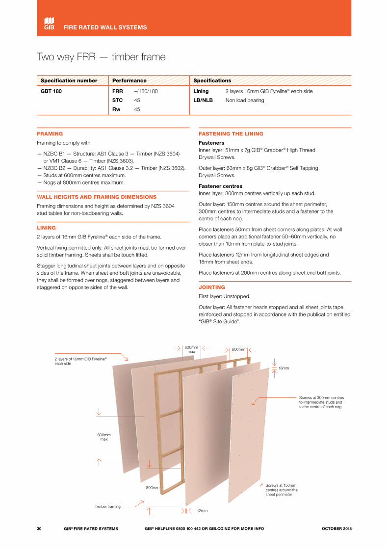
GBT 180 FRR
STC
Rw
–/180/180
45
45
Lining
LB/NLB
2 layers 16mm GIB Fyreline® each side
Non load bearing
FRAMING
Framing to comply with:
— NZBC B1 — Structure: AS1 Clause 3 — Timber (NZS 3604) or VM1 Clause 6 — Timber (NZS 3603).
— NZBC B2 — Durability: AS1 Clause 3.2 — Timber (NZS 3602).— Studs at 600mm centres maximum.— Nogs at 800mm centres maximum.
WALL HEIGHTS AND FRAMING DIMENSIONS
Framing dimensions and height as determined by NZS 3604 stud tables for non-loadbearing walls.
LINING
2 layers of 16mm GIB Fyreline® each side of the frame.
Vertical fixing permitted only. All sheet joints must be formed over solid timber framing. Sheets shall be touch fitted.
Stagger longitudinal sheet joints between layers and on opposite sides of the frame. When sheet end butt joints are unavoidable, they shall be formed over nogs, staggered between layers and staggered on opposite sides of the wall.
FASTENING THE LINING
Fasteners Inner layer: 51mm x 7g GIB® Grabber® High Thread Drywall Screws.
Outer layer: 63mm x 8g GIB® Grabber® Self Tapping Drywall Screws.
Fastener centres Inner layer: 800mm centres vertically up each stud.
Outer layer: 150mm centres around the sheet perimeter, 300mm centres to intermediate studs and a fastener to the centre of each nog.
Place fasteners 50mm from sheet corners along plates. At wall corners place an additional fastener 50–60mm vertically, no closer than 10mm from plate-to-stud joints.
Place fasteners 12mm from longitudinal sheet edges and 18mm from sheet ends.
Place fasteners at 200mm centres along sheet end butt joints.
JOINTING
First layer: Unstopped.
Outer layer: All fastener heads stopped and all sheet joints tape reinforced and stopped in accordance with the publication entitled “GIB® Site Guide”.
800mm
2 layers of 16mm GIB Fyreline® each side
Timber framing
Screws at 300mm centres to intermediate studs and to the centre of each nog
12mm
Screws at 150mm centres around the sheet perimeter
600mm max
18mm
600mm
800mmmax
30 GIB® FIRE RATED SYSTEMS GIB® HELPLINE 0800 100 442 OR GIB.CO.NZ FOR MORE INFO OCTOBER 2018
FIRE RATED WALL SYSTEMS

31GIB® FIRE RATED SYSTEMSGIB® HELPLINE 0800 100 442 OR GIB.CO.NZ FOR MORE INFOOCTOBER 2018

Two way FRR — steel frame
Specification number Performance Specifications
GBSL 15 FRR
STC
Rw
15/15/15
35
35
Lining
LB/NLB
1 layer 13mm GIB® Standard each side
Load bearing
FRAMING AND WALL HEIGHT
Any steel frame designed to meet structural criteria for strength and serviceability under dead and live loads.
Stud width shall be 35mm minimum.
Stud spacing at 600mm centres maximum. Frame height as determined by specific design.
LINING
1 layer of 13mm GIB® Standard each side of the frame.
Vertical or horizontal fixing permitted. For vertical fixing, full height sheets shall be used where possible. When fixing horizontally all longitudinal sheet joints must be formed over nogs.
When sheet end butt joints are unavoidable, they shall be formed over nogs and staggered.
Offset joints between sheets on opposite sides of the frame.
Sheets shall be touch fitted.
All sheet joints must be formed over framing.
Linings are installed hard to floor.
FASTENING THE LINING
Fasteners 25mm x 6g GIB® Grabber® Self Tapping Drywall Screws.
Fastener centres 300mm centres up each stud.
Place fasteners 12mm from longitudinal sheet edges and 50mm from sheet ends.
Place fasteners at 200mm centres along sheet end butt joints.
JOINTING
All screw heads stopped and all sheet joints tape reinforced and stopped in accordance with the publication entitled “GIB® Site Guide”.
Note: See also page 14, “Steel-framed Walls — Load bearing (LB) walls”.
Screws at 300mm centres up each stud
1 layer of 13mm GIB® Standard each side
Steel framing
Linings are installed hard to the floor
12mm
600mm max
50mm
Offset joints between sheets on opposite sides of the frame
32 GIB® FIRE RATED SYSTEMS GIB® HELPLINE 0800 100 442 OR GIB.CO.NZ FOR MORE INFO OCTOBER 2018
FIRE RATED WALL SYSTEMS

Two way FRR — steel frame
Specification number Performance Specifications
GBS 30 FRR
STC
Rw
–/30/30
35
35
Lining
LB/NLB
1 layer 13mm GIB® Standard each side
Non load bearing
FRAMING AND WALL HEIGHT
Minimum steel stud dimensions to be 64 x 34 x 0.50mm nominal with a 6mm return.
Minimum steel channel dimensions to be 64 x 30 x 0.50mm nominal.
Top and bottom channels are fixed to the floor and ceiling in true alignment.
Stud spacing at 600mm centres maximum.
Place studs to allow the nominated expansion gap at the top of the frame.
The studs are held in place by the “grip” of the channels.
Recommended maximum wall heightNote that maximum wall heights for fire rated systems can be lower than what can be achieved with non-fire rated construction.
Nominal stud dimension (mm)
BMT (mm)
Stud centres (mm)
Max wall height (mm)
Expansion at top of studs (mm)
64 x 34 0.50600 3000 15
400 3200 15
76 x 34
0.55600 3200 15
400 3800 20*
0.75600 3600 20*
400 4200 20*
92 x 34 0.75600 4200 20*
400 4800 25*
*Use a minimum 50mm-deep head channel.
LINING
1 layer of 13mm GIB® Standard each side of the frame.
Vertical fixing only permitted. Full height sheets shall be used where possible.
When sheet end butt joints are unavoidable, they shall be formed over nogs and staggered.
Offset joints between sheets on opposite sides of the frame.
Sheets shall be touch fitted.
All sheet joints must be formed over framing.
Linings are installed hard to floor.
FASTENING THE LINING
Fasteners 25mm x 6g GIB® Grabber® Self Tapping Drywall Screws.
Fastener centres 300mm centres up each stud.
Place fasteners 12mm from longitudinal sheet edges and 50mm from sheet ends.
Place fasteners at 200mm centres along sheet end butt joints.
Fastening the linings at 18mm from sheet ends to top and bottom channels is permitted as long as the fasteners do not connect the studs and channels. Do not fix linings to the top track when floor deflection has to be accommodated.
SERVICES
Holes may be drilled or pre-punched in the metal studs to allow installation of electrical service lines and plumbing supply pipes.
JOINTING
All screw heads stopped and all sheet joints tape reinforced and stopped in accordance with the publication entitled “GIB® Site Guide”.
Screws at 300mm centres up each stud
1 layer of 13mm GIB® Standard each side
Studs placed to allow an expansion gap at the top of the frame
Steel framing
Linings are installed hard to the floor
12mm
600mm max
50mm
Offset joints between sheets on opposite sides of the frame
33GIB® FIRE RATED SYSTEMSGIB® HELPLINE 0800 100 442 OR GIB.CO.NZ FOR MORE INFOOCTOBER 2018
FIRE RATED WALL SYSTEMS

Two way FRR — steel frame
Specification number Performance Specifications
GBSL 30a FRR
STC
Rw
30/30/30
40
40
Lining
LB/NLB
1 layer 16mm GIB Fyreline® each side
Load bearing
GBSL 30b FRR
STC
Rw
30/30/30
45
45
Lining
LB/NLB
2 layers 10mm GIB Fyreline® each side
Load bearing
FRAMING AND WALL HEIGHT
Any steel frame designed to meet structural criteria for strength and serviceability under dead and live loads.
Stud width shall be 35mm minimum.
Stud spacing at 600mm centres maximum. Frame height as determined by specific design.
LINING
GBSL 30a — 1 layer of 16mm GIB Fyreline® each side of the frame.
GBSL 30b — 2 layers of 10mm GIB Fyreline® each side of the frame.
Vertical or horizontal fixing permitted. For vertical fixing, full height sheets shall be used where possible. When fixing horizontally, all longitudinal sheet joints must be formed over nogs.
When sheet end butt joints are unavoidable, they shall be formed over nogs and staggered.
Offset joints on opposite sides of the frame and between sheets in double-layered systems.
Sheets shall be touch fitted.
All sheet joints must be formed over framing.
Linings are installed hard to floor.
FASTENING THE LINING
Fasteners GBSL 30a — 32mm x 6g GIB® Grabber® Self Tapping Drywall Screws.
GBSL 30b inner layer — 25mm x 6g GIB® Grabber® Self Tapping Drywall Screws.
GBSL 30b outer layer – 32mm x 6g GIB® Grabber® Self Tapping Drywall Screws.
Fastener centres Inner layer: 600mm centres up each stud.
Outer or single layer: 300mm centres up each stud.
Place fasteners 12mm from longitudinal sheet edges and 50mm from sheet ends.
Place fasteners at 200mm centres along sheet end butt joints.
JOINTING
Inner layer: Unstopped.
Single or outer layers: All screw heads stopped and all sheet joints tape reinforced and stopped in accordance with the publication entitled “GIB® Site Guide”.
Note: See also page 14, “Steel-framed Walls — Load bearing (LB) walls”.
Screws at 300mm centres up each stud
Screws at 300mm centres up each stud
1 layer of 16mm GIB Fyreline® each side
2 layers of 10mm GIB Fyreline® each side
GBSL 30a GBSL 30b
Steel framing Steel framing
Linings are installed hard to the floor
Linings are installed hard to the floor
600mm max
12mm 12mm
50mm
50mm
Offset joints between sheets on opposite sides of the frame
Offset joints between sheets and on opposite sides of the frame
600mm
600mmmax
34 GIB® FIRE RATED SYSTEMS GIB® HELPLINE 0800 100 442 OR GIB.CO.NZ FOR MORE INFO OCTOBER 2018
FIRE RATED WALL SYSTEMS
Two way FRR — steel frame
Specification number Performance Specifications
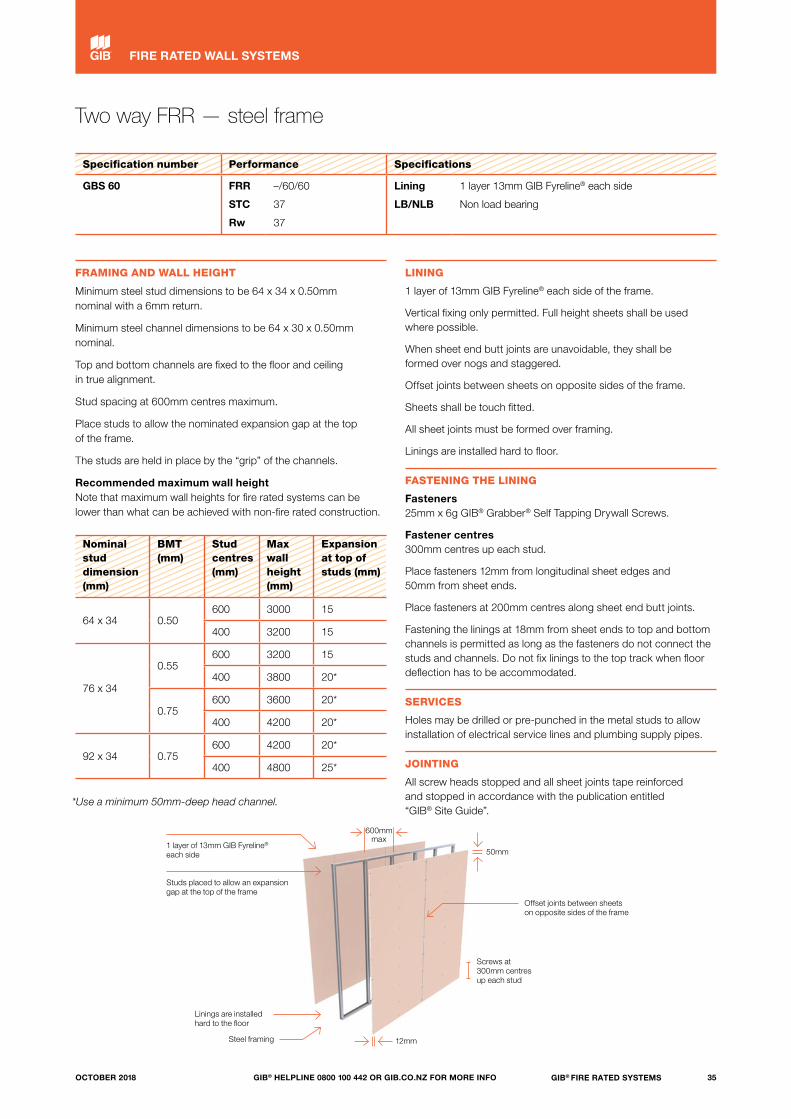
GBS 60 FRR
STC
Rw
–/60/60
37
37
Lining
LB/NLB
1 layer 13mm GIB Fyreline® each side
Non load bearing
FRAMING AND WALL HEIGHT
Minimum steel stud dimensions to be 64 x 34 x 0.50mm nominal with a 6mm return.
Minimum steel channel dimensions to be 64 x 30 x 0.50mm nominal.
Top and bottom channels are fixed to the floor and ceiling in true alignment.
Stud spacing at 600mm centres maximum.
Place studs to allow the nominated expansion gap at the top of the frame.
The studs are held in place by the “grip” of the channels.
Recommended maximum wall height Note that maximum wall heights for fire rated systems can be lower than what can be achieved with non-fire rated construction.
Nominal stud dimension (mm)
BMT (mm)
Stud centres (mm)
Max wall height (mm)
Expansion at top of studs (mm)
64 x 34 0.50600 3000 15
400 3200 15
76 x 34
0.55600 3200 15
400 3800 20*
0.75600 3600 20*
400 4200 20*
92 x 34 0.75600 4200 20*
400 4800 25*
*Use a minimum 50mm-deep head channel.
LINING
1 layer of 13mm GIB Fyreline® each side of the frame.
Vertical fixing only permitted. Full height sheets shall be used where possible.
When sheet end butt joints are unavoidable, they shall be formed over nogs and staggered.
Offset joints between sheets on opposite sides of the frame.
Sheets shall be touch fitted.
All sheet joints must be formed over framing.
Linings are installed hard to floor.
FASTENING THE LINING
Fasteners 25mm x 6g GIB® Grabber® Self Tapping Drywall Screws.
Fastener centres 300mm centres up each stud.
Place fasteners 12mm from longitudinal sheet edges and 50mm from sheet ends.
Place fasteners at 200mm centres along sheet end butt joints.
Fastening the linings at 18mm from sheet ends to top and bottom channels is permitted as long as the fasteners do not connect the studs and channels. Do not fix linings to the top track when floor deflection has to be accommodated.
SERVICES
Holes may be drilled or pre-punched in the metal studs to allow installation of electrical service lines and plumbing supply pipes.
JOINTING
All screw heads stopped and all sheet joints tape reinforced and stopped in accordance with the publication entitled “GIB® Site Guide”.
Screws at 300mm centres up each stud
1 layer of 13mm GIB Fyreline® each side
Studs placed to allow an expansion gap at the top of the frame
Steel framing
Linings are installed hard to the floor
12mm
600mm max
50mm
Offset joints between sheets on opposite sides of the frame
35GIB® FIRE RATED SYSTEMSGIB® HELPLINE 0800 100 442 OR GIB.CO.NZ FOR MORE INFOOCTOBER 2018
FIRE RATED WALL SYSTEMS
Two way FRR — steel frame
Specification number Performance Specifications
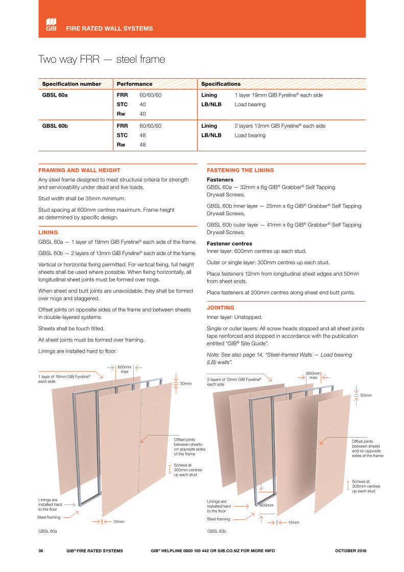
GBSL 60a FRR
STC
Rw
60/60/60
40
40
Lining
LB/NLB
1 layer 19mm GIB Fyreline® each side
Load bearing
GBSL 60b FRR
STC
Rw
60/60/60
48
48
Lining
LB/NLB
2 layers 13mm GIB Fyreline® each side
Load bearing
FRAMING AND WALL HEIGHT
Any steel frame designed to meet structural criteria for strength and serviceability under dead and live loads.
Stud width shall be 35mm minimum.
Stud spacing at 600mm centres maximum. Frame height as determined by specific design.
LINING
GBSL 60a — 1 layer of 19mm GIB Fyreline® each side of the frame.
GBSL 60b — 2 layers of 13mm GIB Fyreline® each side of the frame.
Vertical or horizontal fixing permitted. For vertical fixing, full height sheets shall be used where possible. When fixing horizontally, all longitudinal sheet joints must be formed over nogs.
When sheet end butt joints are unavoidable, they shall be formed over nogs and staggered.
Offset joints on opposite sides of the frame and between sheets in double-layered systems.
Sheets shall be touch fitted.
All sheet joints must be formed over framing.
Linings are installed hard to floor.
FASTENING THE LINING
Fasteners GBSL 60a — 32mm x 6g GIB® Grabber® Self Tapping Drywall Screws.
GBSL 60b inner layer — 25mm x 6g GIB® Grabber® Self Tapping Drywall Screws.
GBSL 60b outer layer — 41mm x 6g GIB® Grabber® Self Tapping Drywall Screws.
Fastener centres Inner layer: 600mm centres up each stud.
Outer or single layer: 300mm centres up each stud.
Place fasteners 12mm from longitudinal sheet edges and 50mm from sheet ends.
Place fasteners at 200mm centres along sheet end butt joints.
JOINTING
Inner layer: Unstopped.
Single or outer layers: All screw heads stopped and all sheet joints tape reinforced and stopped in accordance with the publication entitled “GIB® Site Guide”.
Note: See also page 14, “Steel-framed Walls — Load bearing (LB) walls”.
Screws at 300mm centres up each stud
Screws at 300mm centres up each stud
1 layer of 19mm GIB Fyreline® each side 2 layers of 13mm GIB Fyreline®
each side
GBSL 60a GBSL 60b
Steel framing
Linings are installed hard to the floor
Linings are installed hard to the floor
600mm max
12mm 12mm
50mm
50mm
Offset joints between sheets on opposite sides of the frame
Offset joints between sheets and on opposite sides of the frame
600mm
Steel framing
600mmmax
36 GIB® FIRE RATED SYSTEMS GIB® HELPLINE 0800 100 442 OR GIB.CO.NZ FOR MORE INFO OCTOBER 2018
FIRE RATED WALL SYSTEMS
Two way FRR — steel frame
Specification number Performance Specifications
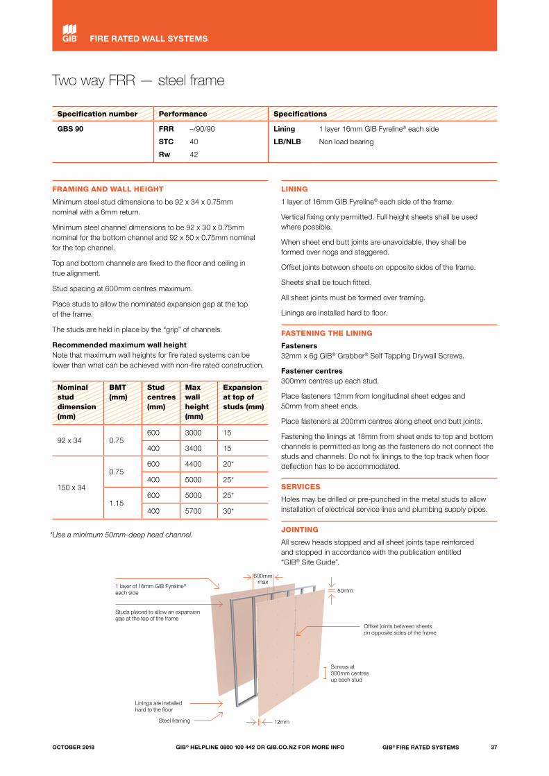
GBS 90 FRR
STC
Rw
–/90/90
40
42
Lining
LB/NLB
1 layer 16mm GIB Fyreline® each side
Non load bearing
FRAMING AND WALL HEIGHT
Minimum steel stud dimensions to be 92 x 34 x 0.75mm nominal with a 6mm return.
Minimum steel channel dimensions to be 92 x 30 x 0.75mm nominal for the bottom channel and 92 x 50 x 0.75mm nominal for the top channel.
Top and bottom channels are fixed to the floor and ceiling in true alignment.
Stud spacing at 600mm centres maximum.
Place studs to allow the nominated expansion gap at the top of the frame.
The studs are held in place by the “grip” of channels.
Recommended maximum wall height Note that maximum wall heights for fire rated systems can be lower than what can be achieved with non-fire rated construction.
Nominal stud dimension (mm)
BMT (mm)
Stud centres (mm)
Max wall height (mm)
Expansion at top of studs (mm)
92 x 34 0.75600 3000 15
400 3400 15
150 x 34
0.75600 4400 20*
400 5000 25*
1.15600 5000 25*
400 5700 30*
*Use a minimum 50mm-deep head channel.
LINING
1 layer of 16mm GIB Fyreline® each side of the frame.
Vertical fixing only permitted. Full height sheets shall be used where possible.
When sheet end butt joints are unavoidable, they shall be formed over nogs and staggered.
Offset joints between sheets on opposite sides of the frame.
Sheets shall be touch fitted.
All sheet joints must be formed over framing.
Linings are installed hard to floor.
FASTENING THE LINING
Fasteners 32mm x 6g GIB® Grabber® Self Tapping Drywall Screws.
Fastener centres 300mm centres up each stud.
Place fasteners 12mm from longitudinal sheet edges and 50mm from sheet ends.
Place fasteners at 200mm centres along sheet end butt joints.
Fastening the linings at 18mm from sheet ends to top and bottom channels is permitted as long as the fasteners do not connect the studs and channels. Do not fix linings to the top track when floor deflection has to be accommodated.
SERVICES
Holes may be drilled or pre-punched in the metal studs to allow installation of electrical service lines and plumbing supply pipes.
JOINTING
All screw heads stopped and all sheet joints tape reinforced and stopped in accordance with the publication entitled “GIB® Site Guide”.
Screws at 300mm centres up each stud
1 layer of 16mm GIB Fyreline® each side
Studs placed to allow an expansion gap at the top of the frame
Steel framing
Linings are installed hard to the floor
12mm
600mm max
50mm
Offset joints between sheets on opposite sides of the frame
37GIB® FIRE RATED SYSTEMSGIB® HELPLINE 0800 100 442 OR GIB.CO.NZ FOR MORE INFOOCTOBER 2018
FIRE RATED WALL SYSTEMS

Two way FRR — steel frame
Specification number Performance Specifications
GBS 90b FRR
STC
Rw
–/90/90
43 (51 with Pink® Batts® R1.2 (50mm) glass wool insulation in both frames)
45 (53 with Pink® Batts® R1.2 (50mm) glass wool insulation in both frames)
Lining
LB/NLB
1 layer 13mm GIB Fyreline® each side of a double-stud frame with a 13mm GIB Fyreline® central barrier
Non load bearing
GBS 60b* FRR
STC
Rw
–/60/60
42 (50 with Pink® Batts® R1.2 (50mm) glass wool insulation in both frames)
44 (52 with Pink® Batts® R1.2 (50mm) glass wool insulation in both frames)
Lining
LB/NLB
1 layer 13mm GIB Fyreline® each side of a double-stud frame with a 13mm GIB Fyreline® central barrier
Non load bearing
FRAMING AND WALL HEIGHT
Minimum steel stud dimensions to be 64 x 34 x 0.50mm nominal with a 6mm return.
Minimum steel channel dimensions to be 64 x 30 x 0.50mm nominal.
Top and bottom channels are fixed to the floor and ceiling in true alignment.
Stud spacing at 600mm centres maximum.
Place studs to allow a 15mm expansion gap at the top of the frame.
The studs are held in place by the “grip” of the channels.
Recommended maximum height for studs at 600mm centres is:
— 3000mm for 64 x 34 x 0.50 BMT framing— 3600mm for 76 x 34 x 0.75 BMT framing, and— 4200mm for 92 x 34 x 0.75 BMT framing.
For wall heights greater than 3000mm, use a minimum 50mm-deep head channel and 20mm expansion tolerance at the top of the studs.
LINING
1 layer of 13mm GIB Fyreline® (the central barrier) to one side of the first frame.
Erect the second frame against the central barrier with studs offset nominally 300mm and no less than 200mm from the first frame and fix the first layer of 13mm GIB Fyreline® (the central barrier) to the second frame.
Complete the assembly by lining the open side of both frames with a single layer of 13mm GIB Fyreline®.
Vertical fixing only permitted. Full height sheets shall be used where possible.
When sheet end butt joints are unavoidable, they shall be formed over nogs and staggered.
Sheets shall be touch fitted.
All sheet joints must be formed over framing.
Linings are installed hard to floor.
FASTENING THE LINING
Fasteners 32mm x 6g GIB® Grabber® Self Tapping Drywall Screws.
Fastener centres 300mm centres up each stud.
Place fasteners 12mm from longitudinal sheet edges and 50mm from sheet ends.
Place fasteners at 200mm centres along sheet end butt joints.
Fastening the linings at 18mm from sheet ends to top and bottom channels is permitted as long as the fasteners do not connect the studs and channels. Do not fix linings to the top track when floor deflection has to be accommodated.
SERVICES
Holes may be drilled or pre-punched in the metal studs to allow installation of electrical service lines and plumbing supply pipes.
Without penetrations in the outer linings, the system achieves a –/90/90 FRR.
*The FRR is reduced to –/60/60 when the central barrier remains intact but metal or PVC plumbing services up to 90 x 50mm rectangular or 65mm in diameter penetrate the outer linings, without specialist fire stopping. Penetrations must be limited to 2 per stud bay and have neatly cut holes with 6mm maximum clearance filled with either a general purpose flexible sealant or GIB Fire Soundseal®.
JOINTING
All screw heads of the outer layers stopped and all sheet joints tape reinforced and stopped in accordance with the publication entitled “GIB® Site Guide”.
The central barrier does not require plaster stopping.
38 GIB® FIRE RATED SYSTEMS GIB® HELPLINE 0800 100 442 OR GIB.CO.NZ FOR MORE INFO OCTOBER 2018
FIRE RATED WALL SYSTEMS
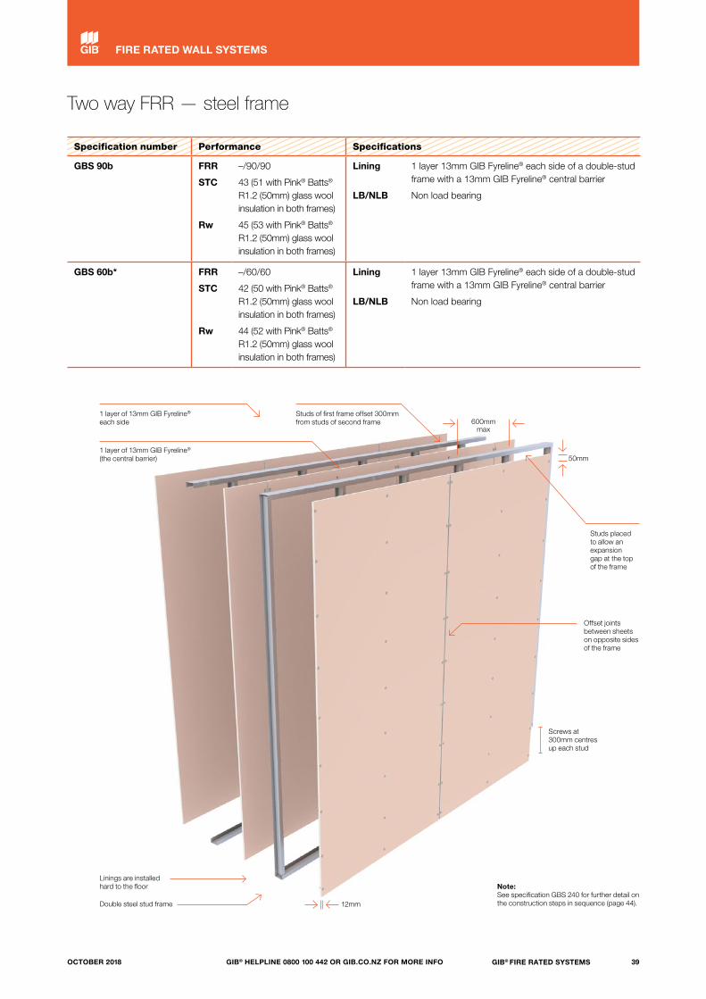
Two way FRR — steel frame
Specification number Performance Specifications
GBS 90b FRR
STC
Rw
–/90/90
43 (51 with Pink® Batts® R1.2 (50mm) glass wool insulation in both frames)
45 (53 with Pink® Batts® R1.2 (50mm) glass wool insulation in both frames)
Lining
LB/NLB
1 layer 13mm GIB Fyreline® each side of a double-stud frame with a 13mm GIB Fyreline® central barrier
Non load bearing
GBS 60b* FRR
STC
Rw
–/60/60
42 (50 with Pink® Batts® R1.2 (50mm) glass wool insulation in both frames)
44 (52 with Pink® Batts® R1.2 (50mm) glass wool insulation in both frames)
Lining
LB/NLB
1 layer 13mm GIB Fyreline® each side of a double-stud frame with a 13mm GIB Fyreline® central barrier
Non load bearing
1 layer of 13mm GIB Fyreline® each side
Studs of first frame offset 300mm from studs of second frame
Studs placed to allow an expansion gap at the top of the frame
Double steel stud frame
1 layer of 13mm GIB Fyreline® (the central barrier)
Screws at 300mm centres up each stud
Linings are installed hard to the floor
12mm
Offset joints between sheets on opposite sides of the frame
600mm max
50mm
Note: See specification GBS 240 for further detail on the construction steps in sequence (page 44).
39GIB® FIRE RATED SYSTEMSGIB® HELPLINE 0800 100 442 OR GIB.CO.NZ FOR MORE INFOOCTOBER 2018
FIRE RATED WALL SYSTEMS

Two way FRR — steel frame
Specification number Performance Specifications
GBSL 90 FRR
STC
Rw
90/90/90
47
46
Lining
LB/NLB
1 layer 16mm GIB Fyreline® and 1 layer 13mm GIB Fyreline® each side
Load bearing
FRAMING AND WALL HEIGHT
Any steel frame designed to meet structural criteria for strength and serviceability under dead and live loads.
Stud width shall be 35mm minimum.
Stud spacing at 600mm centres maximum. Frame height as determined by specific design.
LINING
1 layer of 16mm GIB Fyreline® plus 1 layer of 13mm GIB Fyreline® each side of the frame.
Vertical or horizontal fixing permitted. For vertical fixing, full height sheets shall be used where possible. When fixing horizontally, all longitudinal sheet joints must be formed over nogs.
When sheet end butt joints are unavoidable, they shall be formed over nogs and staggered.
Offset joints on opposite sides of the frame and between sheets in double-layered systems.
Sheets shall be touch fitted.
All sheet joints must be formed over framing.
Linings are installed hard to floor.
FASTENING THE LINING
Fasteners Inner layer: 16mm GIB Fyreline® – 32mm x 6g GIB® Grabber® Self Tapping Drywall Screws.
Outer layer: 13mm GIB Fyreline® – 41mm x 6g GIB® Grabber® Self Tapping Drywall Screws.
Fastener centres Inner layer: 600mm centres up each stud.
Outer layer: 300mm centres up each stud.
Place fasteners 12mm from longitudinal sheet edges and 50mm from sheet ends.
Place fasteners at 200mm centres along sheet end butt joints.
JOINTING
Inner layer: Unstopped.
Outer layer: All screw heads stopped and all sheet joints tape reinforced and stopped in accordance with the publication entitled “GIB® Site Guide”.
Note: See also page 14, “Steel-framed Walls — Load bearing (LB) walls”.
Screws at 300mm centres up each stud
1 layer of 16mm GIB Fyreline® and 1 layer of 13mm GIB Fyreline® each side
Steel framing
Linings are installed hard to the floor
12mm
50mm
Offset joints between sheets and on opposite sides of the frame
600mm
600mm max
40 GIB® FIRE RATED SYSTEMS GIB® HELPLINE 0800 100 442 OR GIB.CO.NZ FOR MORE INFO OCTOBER 2018
FIRE RATED WALL SYSTEMS
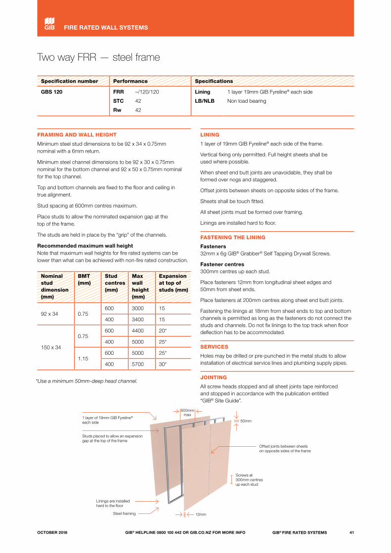
Two way FRR — steel frame
Specification number Performance Specifications
GBS 120 FRR
STC
Rw
–/120/120
42
42
Lining
LB/NLB
1 layer 19mm GIB Fyreline® each side
Non load bearing
FRAMING AND WALL HEIGHT
Minimum steel stud dimensions to be 92 x 34 x 0.75mm nominal with a 6mm return.
Minimum steel channel dimensions to be 92 x 30 x 0.75mm nominal for the bottom channel and 92 x 50 x 0.75mm nominal for the top channel.
Top and bottom channels are fixed to the floor and ceiling in true alignment.
Stud spacing at 600mm centres maximum.
Place studs to allow the nominated expansion gap at the top of the frame.
The studs are held in place by the “grip” of the channels.
Recommended maximum wall height Note that maximum wall heights for fire rated systems can be lower than what can be achieved with non-fire rated construction.
Nominal stud dimension (mm)
BMT (mm)
Stud centres (mm)
Max wall height (mm)
Expansion at top of studs (mm)
92 x 34 0.75600 3000 15
400 3400 15
150 x 34
0.75600 4400 20*
400 5000 25*
1.15600 5000 25*
400 5700 30*
*Use a minimum 50mm-deep head channel.
LINING
1 layer of 19mm GIB Fyreline® each side of the frame.
Vertical fixing only permitted. Full height sheets shall be used where possible.
When sheet end butt joints are unavoidable, they shall be formed over nogs and staggered.
Offset joints between sheets on opposite sides of the frame.
Sheets shall be touch fitted.
All sheet joints must be formed over framing.
Linings are installed hard to floor.
FASTENING THE LINING
Fasteners 32mm x 6g GIB® Grabber® Self Tapping Drywall Screws.
Fastener centres 300mm centres up each stud.
Place fasteners 12mm from longitudinal sheet edges and 50mm from sheet ends.
Place fasteners at 200mm centres along sheet end butt joints.
Fastening the linings at 18mm from sheet ends to top and bottom channels is permitted as long as the fasteners do not connect the studs and channels. Do not fix linings to the top track when floor deflection has to be accommodated.
SERVICES
Holes may be drilled or pre-punched in the metal studs to allow installation of electrical service lines and plumbing supply pipes.
JOINTING
All screw heads stopped and all sheet joints tape reinforced and stopped in accordance with the publication entitled “GIB® Site Guide”.
Screws at 300mm centres up each stud
1 layer of 19mm GIB Fyreline® each side
Studs placed to allow an expansion gap at the top of the frame
Steel framing
Linings are installed hard to the floor
12mm
600mm max
50mm
Offset joints between sheets on opposite sides of the frame
41GIB® FIRE RATED SYSTEMSGIB® HELPLINE 0800 100 442 OR GIB.CO.NZ FOR MORE INFOOCTOBER 2018
FIRE RATED WALL SYSTEMS
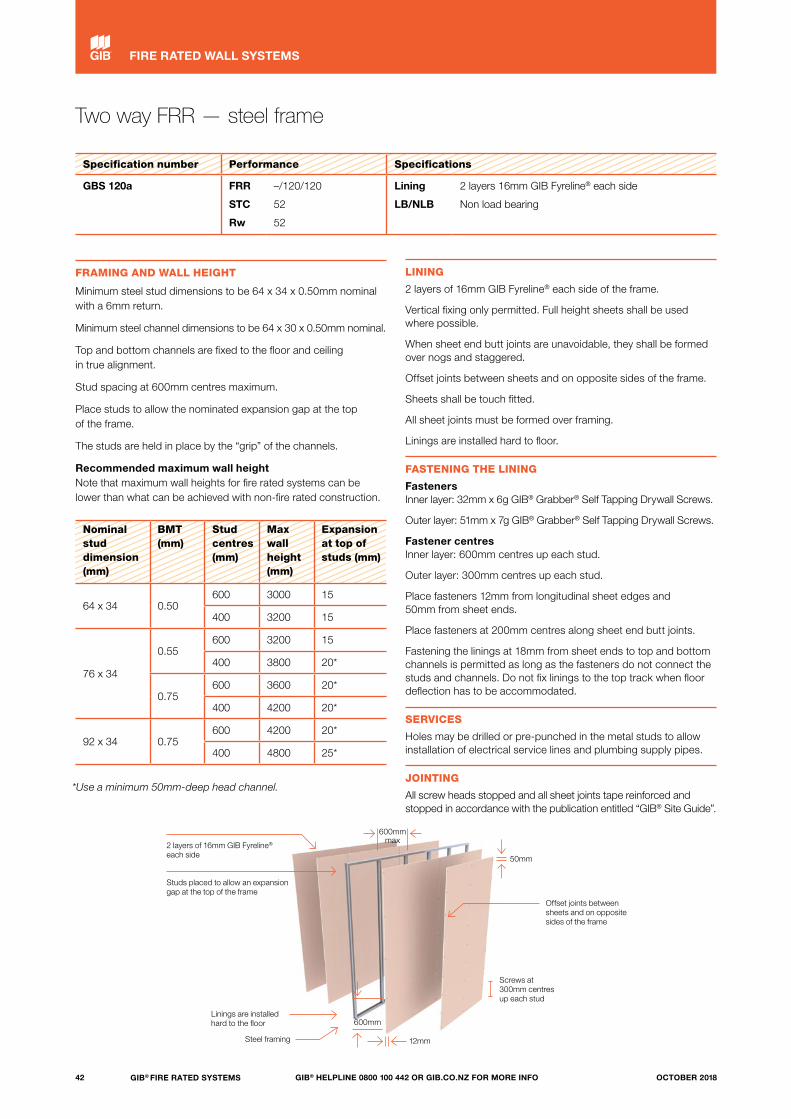
Two way FRR — steel frame
Specification number Performance Specifications
GBS 120a FRR
STC
Rw
–/120/120
52
52
Lining
LB/NLB
2 layers 16mm GIB Fyreline® each side
Non load bearing
FRAMING AND WALL HEIGHT
Minimum steel stud dimensions to be 64 x 34 x 0.50mm nominal with a 6mm return.
Minimum steel channel dimensions to be 64 x 30 x 0.50mm nominal.
Top and bottom channels are fixed to the floor and ceiling in true alignment.
Stud spacing at 600mm centres maximum.
Place studs to allow the nominated expansion gap at the top of the frame.
The studs are held in place by the “grip” of the channels.
Recommended maximum wall height Note that maximum wall heights for fire rated systems can be lower than what can be achieved with non-fire rated construction.
Nominal stud dimension (mm)
BMT (mm)
Stud centres (mm)
Max wall height (mm)
Expansion at top of studs (mm)
64 x 34 0.50600 3000 15
400 3200 15
76 x 34
0.55600 3200 15
400 3800 20*
0.75600 3600 20*
400 4200 20*
92 x 34 0.75600 4200 20*
400 4800 25*
*Use a minimum 50mm-deep head channel.
LINING
2 layers of 16mm GIB Fyreline® each side of the frame.
Vertical fixing only permitted. Full height sheets shall be used where possible.
When sheet end butt joints are unavoidable, they shall be formed over nogs and staggered.
Offset joints between sheets and on opposite sides of the frame.
Sheets shall be touch fitted.
All sheet joints must be formed over framing.
Linings are installed hard to floor.
FASTENING THE LINING
Fasteners Inner layer: 32mm x 6g GIB® Grabber® Self Tapping Drywall Screws.
Outer layer: 51mm x 7g GIB® Grabber® Self Tapping Drywall Screws.
Fastener centres Inner layer: 600mm centres up each stud.
Outer layer: 300mm centres up each stud.
Place fasteners 12mm from longitudinal sheet edges and 50mm from sheet ends.
Place fasteners at 200mm centres along sheet end butt joints.
Fastening the linings at 18mm from sheet ends to top and bottom channels is permitted as long as the fasteners do not connect the studs and channels. Do not fix linings to the top track when floor deflection has to be accommodated.
SERVICES
Holes may be drilled or pre-punched in the metal studs to allow installation of electrical service lines and plumbing supply pipes.
JOINTING
All screw heads stopped and all sheet joints tape reinforced and stopped in accordance with the publication entitled “GIB® Site Guide”.
Screws at 300mm centres up each stud
2 layers of 16mm GIB Fyreline® each side
Studs placed to allow an expansion gap at the top of the frame
Steel framing
Linings are installed hard to the floor
600mm max
12mm
50mm
Offset joints between sheets and on opposite sides of the frame
600mm
42 GIB® FIRE RATED SYSTEMS GIB® HELPLINE 0800 100 442 OR GIB.CO.NZ FOR MORE INFO OCTOBER 2018
FIRE RATED WALL SYSTEMS

Two way FRR — steel frame
Specification number Performance Specifications
GBS 120b FRR
STC
Rw
–/120/120
48
48
Lining
LB/NLB
2 layers of 13mm GIB Fyreline® each side
Non load bearing
FRAMING AND WALL HEIGHT
Minimum steel stud dimensions to be 92 x 34 x 0.75mm nominal with a 6mm return.
Minimum steel channel dimensions to be 92 x 30 x 0.75mm nominal for the bottom channel and 92 x 50 x 0.75mm nominal for the top channel.
Top and bottom channels are fixed to the floor and ceiling in true alignment.
Stud spacing at 600mm centres maximum.
Place studs to allow the nominated expansion gap at the top of the frame.
The studs are held in place by the “grip” of the channels.
Recommended maximum wall height Note that maximum wall heights for fire-rated systems can be lower than what can be achieved with non-fire-rated construction.
Nominal stud dimension (mm)
BMT (mm)
Stud centres (mm)
Max wall height (mm)
Expansion at top of studs (mm)
92 x 34 0.75600 3000 15
400 3400 15
150 x 34
0.75600 4400 20*
400 5000 25*
1.15600 5000 25*
400 5700 30*
*Use a minimum 50mm-deep head channel.
LINING
2 layers of 13mm GIB Fyreline® each side of the frame.
Vertical fixing only permitted. Full height sheets shall be used where possible.
When sheet end butt joints are unavoidable, they shall be formed over nogs and staggered.
Offset joints between sheets and on opposite side of frame.
Sheets shall be touch fitted.
All sheet joints must be formed over framing.
Linings are installed hard to floor.
FASTENING THE LINING
Fasteners Inner layer: 32mm x 6g GIB® Grabber® Self Tapping Drywall Screws.
Outer layer: 41mm x 6g GIB® Grabber® Self Tapping Drywall Screws.
Fastener centres Inner layer: 300mm centres up each stud.
Outer layer: 300mm centres up each stud.
Place fasteners 12mm from longitudinal sheet edges and 50mm from sheet ends.
Place fasteners at 200mm centres along sheet end butt joints.
Fastening the linings at 18mm from sheet ends to top and bottom channels is permitted as long as the fasteners do not connect the studs and channels. Do not fix linings to the top track when floor deflection has to be accommodated.
SERVICES
Holes may be drilled or pre-punched in the metal studs to allow installation of electrical service lines and plumbing supply pipes.
JOINTING
All screw heads stopped and all sheet joints tape reinforced and stopped in accordance with the publication entitled “GIB® Site Guide”.
Screws at 300mm centres up each stud
2 layers of 13mm GIB Fyreline® each side
Studs placed to allow an expansion gap at the top of the frame
Steel framing
Linings are installed hard to the floor
600mm max
12mm
50mm
Offset joints between sheets and on opposite sides of the frame
300mm
43GIB® FIRE RATED SYSTEMSGIB® HELPLINE 0800 100 442 OR GIB.CO.NZ FOR MORE INFOOCTOBER 2018
FIRE RATED WALL SYSTEMS
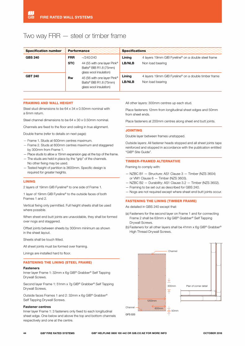
Two way FRR — steel or timber frame
Specification number Performance Specifications
GBS 240 FRR
STC
Rw
–/240/240
44 (55 with one layer Pink® Batts® BIB R1.8 (75mm) glass wool insulation)
45 (56 with one layer Pink® Batts® BIB R1.8 (75mm) glass wool insulation)
Lining
LB/NLB
4 layers 19mm GIB Fyreline® on a double steel frame
Non load bearing
GBT 240 Lining
LB/NLB
4 layers 19mm GIB Fyreline® on a double timber frame
Non load bearing
FRAMING AND WALL HEIGHT
Steel stud dimensions to be 64 x 34 x 0.50mm nominal with a 6mm return.
Steel channel dimensions to be 64 x 30 x 0.50mm nominal.
Channels are fixed to the floor and ceiling in true alignment.
Double frame (refer to details on next page):
— Frame 1. Studs at 600mm centres maximum.— Frame 2. Studs at 600mm centres maximum and staggered
by 300mm from Frame 1.— Place studs to allow a 15mm expansion gap at the top of the frame.— The studs are held in place by the “grip” of the channels.
No other fixing may be used.— Tested height of partition is 3600mm. Specific design is
required for greater heights.
LINING
2 layers of 19mm GIB Fyreline® to one side of Frame 1.
1 layer of 19mm GIB Fyreline® to the outside faces of both Frames 1 and 2.
Vertical fixing only permitted. Full height sheets shall be used where possible.
When sheet end butt joints are unavoidable, they shall be formed over nogs and staggered.
Offset joints between sheets by 300mm minimum as shown in the sheet layout.
Sheets shall be touch fitted.
All sheet joints must be formed over framing.
Linings are installed hard to floor.
FASTENING THE LINING (STEEL FRAME)
Fasteners Inner layer Frame 1: 32mm x 6g GIB® Grabber® Self Tapping Drywall Screws.
Second layer Frame 1: 51mm x 7g GIB® Grabber® Self Tapping Drywall Screws.
Outside faces Frames 1 and 2: 32mm x 6g GIB® Grabber® Self Tapping Drywall Screws.
Fastener centres Inner layer Frame 1: 3 fasteners only fixed to each longitudinal sheet edge. One below and above the top and bottom channels respectively and one at the centre.
All other layers: 300mm centres up each stud.
Place fasteners 12mm from longitudinal sheet edges and 50mm from sheet ends.
Place fasteners at 200mm centres along sheet end butt joints.
JOINTING
Double layer between frames unstopped.
Outside layers: All fastener heads stopped and all sheet joints tape reinforced and stopped in accordance with the publication entitled “GIB® Site Guide”.
TIMBER-FRAMED ALTERNATIVE
Framing to comply with:
— NZBC B1 — Structure: AS1 Clause 3 — Timber (NZS 3604) or VM1 Clause 6 — Timber (NZS 3603).
— NZBC B2 — Durability: AS1 Clause 3.2 — Timber (NZS 3602).— Framing to be set out as described for GBS 240.— Nogs are not required except where sheet end butt joints occur.
FASTENING THE LINING (TIMBER FRAME)
As detailed in GBS 240 except that:
(a) Fasteners for the second layer on Frame 1 and for connecting Frame 2 shall be 63mm x 8g GIB® Grabber® Self Tapping Drywall Screws.
(b) Fasteners for all other layers shall be 41mm x 6g GIB® Grabber® High Thread Drywall Screws.
Plan of corner detail
Channel
Channel
1200mm
600mm50mm
300mm
GFS 020
44 GIB® FIRE RATED SYSTEMS GIB® HELPLINE 0800 100 442 OR GIB.CO.NZ FOR MORE INFO OCTOBER 2018
FIRE RATED WALL SYSTEMS
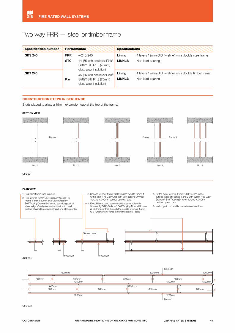
Two way FRR — steel or timber frame
Specification number Performance Specifications
GBS 240 FRR
STC
Rw
–/240/240
44 (55 with one layer Pink® Batts® BIB R1.8 (75mm) glass wool insulation)
45 (56 with one layer Pink® Batts® BIB R1.8 (75mm) glass wool insulation)
Lining
LB/NLB
4 layers 19mm GIB Fyreline® on a double steel frame
Non load bearing
GBT 240 Lining
LB/NLB
4 layers 19mm GIB Fyreline® on a double timber frame
Non load bearing
CONSTRUCTION STEPS IN SEQUENCE
Studs placed to allow a 15mm expansion gap at the top of the frame.
PLAN VIEW
GIB®
© Winstone Wallboards Limited 2014. TERMS OF USE: The USER of these CAD drawings and related information is authorised to reproduce and distribute exact copies or exact extracts of these CAD drawings for the sole purpose of detailing, specifying, using, and promoting the use of Winstone Wallboards Ltd products and systems. It is the USER's responsibility to ensure full building performance specifications and to ensure specification and installation of GIB® products and systems are in accordance with Winstone Wallboards Ltd GIB® publications. Appropriate expert advice should always be obtained to ensure suitability of these drawings for your specific application. See www.gib.co.nz for full terms of use. The USER is deemed to accept the terms of use.
© copyright 2011 Winstone Wallboards Ltd All Dimensions are to be site checked before construction and installation
File:Scale:
Date:
Reference 1 : 10Two Way FRR - Construction SequenceLayout GFS-P038F07 Mar 18
GFS-P038FGIB®
© Winstone Wallboards Limited 2014. TERMS OF USE: The USER of these CAD drawings and related information is authorised to reproduce and distribute exact copies or exact extracts of these CAD drawings for the sole purpose of detailing, specifying, using, and promoting the use of Winstone Wallboards Ltd products and systems. It is the USER's responsibility to ensure full building performance specifications and to ensure specification and installation of GIB® products and systems are in accordance with Winstone Wallboards Ltd GIB® publications. Appropriate expert advice should always be obtained to ensure suitability of these drawings for your specific application. See www.gib.co.nz for full terms of use. The USER is deemed to accept the terms of use.
© copyright 2011 Winstone Wallboards Ltd All Dimensions are to be site checked before construction and installation
File:Scale:
Date:
Reference 1 : 10Two Way FRR - Construction SequenceLayout GFS-P038F07 Mar 18
GFS-P038F
© Winstone Wallboards Limited 2016. TERMS OF USE: The USER of these CAD drawings and related information is authorised to reproduce and distribute exact copies or exact extracts of these CAD drawings for the sole purpose of detailing, specifying, using, and promoting the use of Winstone Wallboards Ltd products and systems. It is the USER's responsibility to ensure full building performance specifications and to ensure specification and installation of GIB® products and
systems are in accordance with Winstone Wallboards Ltd GIB® publications. Appropriate expert advice should always be obtained to ensure suitability of these drawings for your specific application. See www.gib.co.nz for full terms of use. The USER is deemed to accept the terms of use.
© Copyright 2016 Winstone Wallboards Ltd All Dimensions are to be site checked before construction and installation
Issue:
Scale:
Date:
Reference
File:
1 : 5
GFS-P038ATwo Way FRR - Construction Sequence Elevation 01
GFS-P038A07 Mar 18
GFS-P038A Two Way FRR - Construction Sequence Elevation 01
© Winstone Wallboards Limited 2016. TERMS OF USE: The USER of these CAD drawings and related information is authorised to reproduce and distribute exact copies or exact extracts of these CAD drawings for the sole purpose of detailing, specifying, using, and promoting the use of Winstone Wallboards Ltd products and systems. It is the USER's responsibility to ensure full building performance specifications and to ensure specification and installation of GIB® products and
systems are in accordance with Winstone Wallboards Ltd GIB® publications. Appropriate expert advice should always be obtained to ensure suitability of these drawings for your specific application. See www.gib.co.nz for full terms of use. The USER is deemed to accept the terms of use.
© Copyright 2016 Winstone Wallboards Ltd All Dimensions are to be site checked before construction and installation
Issue:
Scale:
Date:
Reference
File:
1 : 5
GFS-P038BTwo Way FRR - Construction Sequence Elevation 02
GFS-P038B07 Mar 18
GFS-P038B Two Way FRR - Construction Sequence Elevation 02
© Winstone Wallboards Limited 2016. TERMS OF USE: The USER of these CAD drawings and related information is authorised to reproduce and distribute exact copies or exact extracts of these CAD drawings for the sole purpose of detailing, specifying, using, and promoting the use of Winstone Wallboards Ltd products and systems. It is the USER's responsibility to ensure full building performance specifications and to ensure specification and installation of GIB® products and
systems are in accordance with Winstone Wallboards Ltd GIB® publications. Appropriate expert advice should always be obtained to ensure suitability of these drawings for your specific application. See www.gib.co.nz for full terms of use. The USER is deemed to accept the terms of use.
© Copyright 2016 Winstone Wallboards Ltd All Dimensions are to be site checked before construction and installation
Issue:
Scale:
Date:
Reference
File:
1 : 5
GFS-P038CTwo Way FRR - Construction Sequence Elevation 03
GFS-P038C07 Mar 18
GFS-P038C Two Way FRR - Construction Sequence Elevation 03
© Winstone Wallboards Limited 2016. TERMS OF USE: The USER of these CAD drawings and related information is authorised to reproduce and distribute exact copies or exact extracts of these CAD drawings for the sole purpose of detailing, specifying, using, and promoting the use of Winstone Wallboards Ltd products and systems. It is the USER's responsibility to ensure full building performance specifications and to ensure specification and installation of GIB® products and
systems are in accordance with Winstone Wallboards Ltd GIB® publications. Appropriate expert advice should always be obtained to ensure suitability of these drawings for your specific application. See www.gib.co.nz for full terms of use. The USER is deemed to accept the terms of use.
© Copyright 2016 Winstone Wallboards Ltd All Dimensions are to be site checked before construction and installation
Issue:
Scale:
Date:
Reference
File:
1 : 5
GFS-P038DTwo Way FRR - Construction Sequence Elevation 04
GFS-P038D07 Mar 18
GFS-P038D Two Way FRR - Construction Sequence Elevation 04
© Winstone Wallboards Limited 2016. TERMS OF USE: The USER of these CAD drawings and related information is authorised to reproduce and distribute exact copies or exact extracts of these CAD drawings for the sole purpose of detailing, specifying, using, and promoting the use of Winstone Wallboards Ltd products and systems. It is the USER's responsibility to ensure full building performance specifications and to ensure specification and installation of GIB® products and
systems are in accordance with Winstone Wallboards Ltd GIB® publications. Appropriate expert advice should always be obtained to ensure suitability of these drawings for your specific application. See www.gib.co.nz for full terms of use. The USER is deemed to accept the terms of use.
© Copyright 2016 Winstone Wallboards Ltd All Dimensions are to be site checked before construction and installation
Issue:
Scale:
Date:
Reference
File:
1 : 5
GFS-P038ETwo Way FRR - Construction Sequence Elevation 05
GFS-P038E07 Mar 18
GFS-P038E Two Way FRR - Construction Sequence Elevation 05
Frame 1
No. 1 No. 2 No. 3 No. 4 No. 5
Frame 1
Frame 2
Second layer
First layerFirst layer
Frame 1
Frame 2
900mm 1200mm 1200mm
300mm 600mm 600mm 600mm
600mm 600mm 600mm 600mm
1200mm
1200mm
1200mm
1200mm
600mm
1200mm
1200mm
1. First steel frame fixed in place.
2. First layer of 19mm GIB Fyreline® “tacked” to Frame 1 with 3/32mm x 6g GIB® Grabber® Self Tapping Drywall Screws to each longitudinal sheet edge. One below and above the top and bottom channels respectively and one at the centre.
5. Fix the outer layer of 19mm GIB Fyreline® to the outside faces of Frames 1 and 2 with 32mm x 6g GIB® Grabber® Self Tapping Drywall Screws at 300mm centres up each stud.
6. No fixings to top and bottom channel sections.
3. Second layer of 19mm GIB Fyreline® fixed to Frame 1 with 51mm x 7g GIB® Grabber® Self Tapping Drywall Screws at 300mm centres up each stud.
4. Erect Frame 2 and secure studs to assembly with 51mm x 7g GIB® Grabber® Self Tapping Drywall Screws at 300mm centres through the double layers of 19mm GIB Fyreline® on Frame 1 (from the Frame 1 side).
GFS 021
GFS 023
GFS 022
SECTION VIEW
45GIB® FIRE RATED SYSTEMSGIB® HELPLINE 0800 100 442 OR GIB.CO.NZ FOR MORE INFOOCTOBER 2018
FIRE RATED WALL SYSTEMS

46 GIB® FIRE RATED SYSTEMS GIB® HELPLINE 0800 100 442 OR GIB.CO.NZ FOR MORE INFO OCTOBER 2018

One way FRR — timber or steel frame
Specification number Performance Specifications
GBUW 15 FRR 15/15/15 Lining
LB/NLB
1 layer 13mm GIB® Standard one side
Load bearing
FRAMING AND WALL HEIGHT
Timber or steel frame designed to meet durability and structural criteria for strength and serviceability under dead and live loads.
The width of framing supporting the linings shall be 35mm minimum.
The cavity depth shall be 90mm minimum.
Framing spacing shall be at 600mm centres maximum.
Timber frame height and dimensions as determined by NZS 3604 stud tables or specific design.
LINING (FIRE SIDE)
1 layer of 13mm GIB® Standard to one side of the frame.
Vertical or horizontal fixing permitted. Full height sheets shall be used where possible.
Sheets shall be touch fitted.
When sheet end butt joints are unavoidable, they shall be formed over framing.
All sheet joints must be formed over framing.
In steel-framed options, linings are installed hard to floor.
FASTENING THE LINING
Fasteners
Timber frame Steel frame
32mm x 6g GIB® Grabber® High Thread Drywall Screws
32mm x 6g GIB® Grabber® Self Tapping Drywall Screws
Fastener centres 300mm centres up each stud.
Place fasteners 12mm from longitudinal sheet edges and 18mm from sheet ends.
Place fasteners at 200mm centres along sheet end butt joints.
JOINTING
All screw heads stopped and all sheet joints tape reinforced and stopped in accordance with the publication entitled “GIB® Site Guide”.
Screws at 300mm centres up each stud
Any cladding system
1 layer of 13mm GIB® Standard one side
Timber or steel framing12mm
600mm max
18mm
47GIB® FIRE RATED SYSTEMSGIB® HELPLINE 0800 100 442 OR GIB.CO.NZ FOR MORE INFOOCTOBER 2018
FIRE RATED WALL SYSTEMS
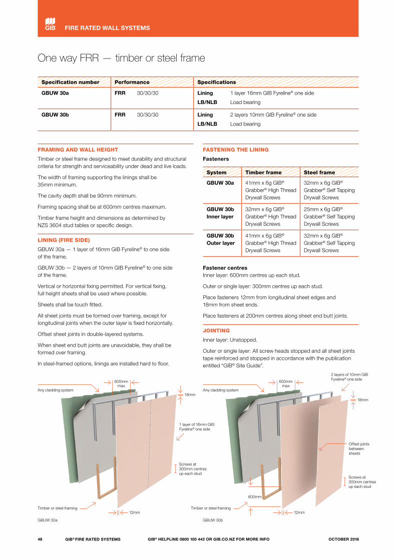
One way FRR — timber or steel frame
Specification number Performance Specifications
GBUW 30a FRR 30/30/30 Lining
LB/NLB
1 layer 16mm GIB Fyreline® one side
Load bearing
GBUW 30b FRR 30/30/30 Lining
LB/NLB
2 layers 10mm GIB Fyreline® one side
Load bearing
FRAMING AND WALL HEIGHT
Timber or steel frame designed to meet durability and structural criteria for strength and serviceability under dead and live loads.
The width of framing supporting the linings shall be 35mm minimum.
The cavity depth shall be 90mm minimum.
Framing spacing shall be at 600mm centres maximum.
Timber frame height and dimensions as determined by NZS 3604 stud tables or specific design.
LINING (FIRE SIDE)
GBUW 30a — 1 layer of 16mm GIB Fyreline® to one side of the frame.
GBUW 30b — 2 layers of 10mm GIB Fyreline® to one side of the frame.
Vertical or horizontal fixing permitted. For vertical fixing, full height sheets shall be used where possible.
Sheets shall be touch fitted.
All sheet joints must be formed over framing, except for longitudinal joints when the outer layer is fixed horizontally.
Offset sheet joints in double-layered systems.
When sheet end butt joints are unavoidable, they shall be formed over framing.
In steel-framed options, linings are installed hard to floor.
FASTENING THE LINING
Fasteners
System Timber frame Steel frame
GBUW 30a 41mm x 6g GIB® Grabber® High Thread Drywall Screws
32mm x 6g GIB® Grabber® Self Tapping Drywall Screws
GBUW 30b Inner layer
32mm x 6g GIB® Grabber® High Thread Drywall Screws
25mm x 6g GIB® Grabber® Self Tapping Drywall Screws
GBUW 30b Outer layer
41mm x 6g GIB® Grabber® High Thread Drywall Screws
32mm x 6g GIB® Grabber® Self Tapping Drywall Screws
Fastener centres Inner layer: 600mm centres up each stud.
Outer or single layer: 300mm centres up each stud.
Place fasteners 12mm from longitudinal sheet edges and 18mm from sheet ends.
Place fasteners at 200mm centres along sheet end butt joints.
JOINTING
Inner layer: Unstopped.
Outer or single layer: All screw heads stopped and all sheet joints tape reinforced and stopped in accordance with the publication entitled “GIB® Site Guide”.
GBUW 30a GBUW 30b
Screws at 300mm centres up each stud
Screws at 300mm centres up each stud
Any cladding system Any cladding system
Timber or steel framing Timber or steel framing
600mm max
600mm max
12mm 12mm
18mm18mm
600mm
Offset joints between sheets
2 layers of 10mm GIB Fyreline® one side
1 layer of 16mm GIB Fyreline® one side
48 GIB® FIRE RATED SYSTEMS GIB® HELPLINE 0800 100 442 OR GIB.CO.NZ FOR MORE INFO OCTOBER 2018
FIRE RATED WALL SYSTEMS
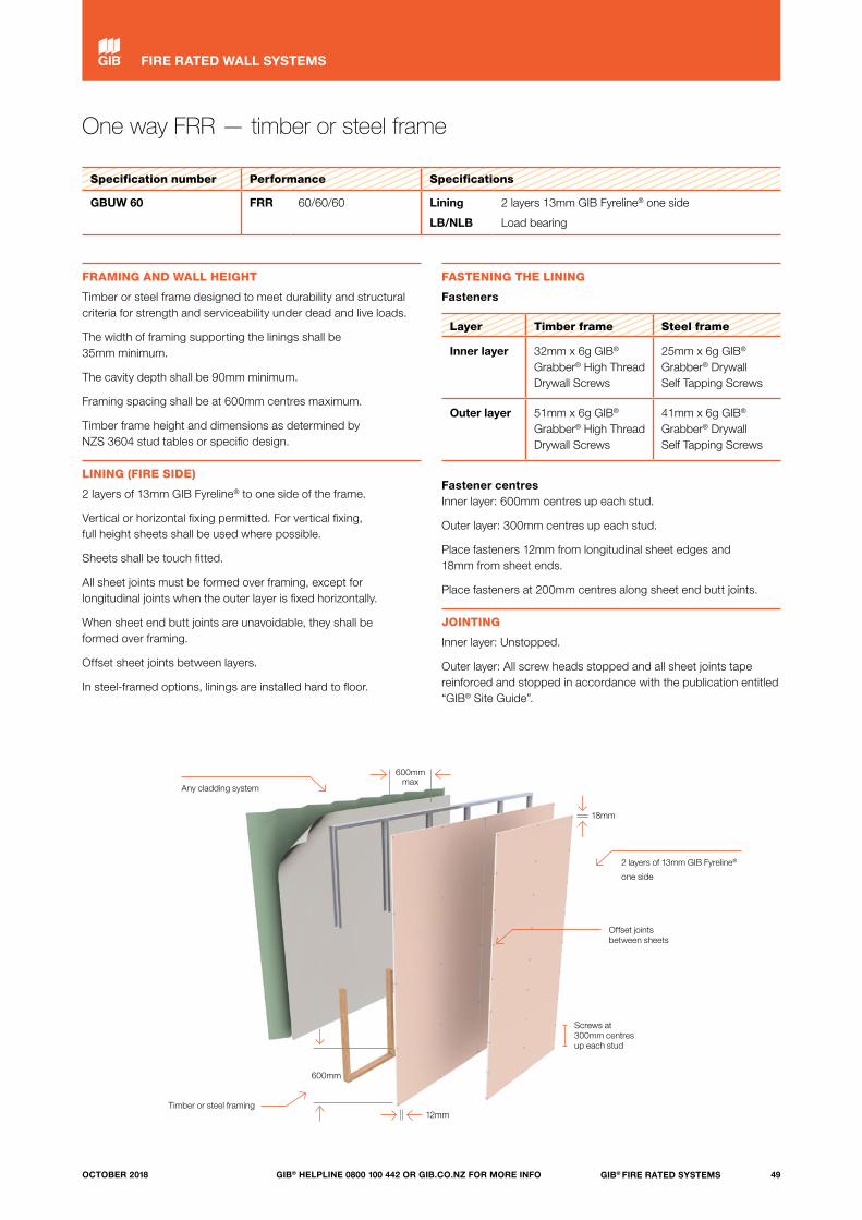
One way FRR — timber or steel frame
Specification number Performance Specifications
GBUW 60 FRR 60/60/60 Lining
LB/NLB
2 layers 13mm GIB Fyreline® one side
Load bearing
FRAMING AND WALL HEIGHT
Timber or steel frame designed to meet durability and structural criteria for strength and serviceability under dead and live loads.
The width of framing supporting the linings shall be 35mm minimum.
The cavity depth shall be 90mm minimum.
Framing spacing shall be at 600mm centres maximum.
Timber frame height and dimensions as determined by NZS 3604 stud tables or specific design.
LINING (FIRE SIDE)
2 layers of 13mm GIB Fyreline® to one side of the frame.
Vertical or horizontal fixing permitted. For vertical fixing, full height sheets shall be used where possible.
Sheets shall be touch fitted.
All sheet joints must be formed over framing, except for longitudinal joints when the outer layer is fixed horizontally.
When sheet end butt joints are unavoidable, they shall be formed over framing.
Offset sheet joints between layers.
In steel-framed options, linings are installed hard to floor.
FASTENING THE LINING
Fasteners
Layer Timber frame Steel frame
Inner layer 32mm x 6g GIB® Grabber® High Thread Drywall Screws
25mm x 6g GIB® Grabber® Drywall Self Tapping Screws
Outer layer 51mm x 6g GIB® Grabber® High Thread Drywall Screws
41mm x 6g GIB® Grabber® Drywall Self Tapping Screws
Fastener centres Inner layer: 600mm centres up each stud.
Outer layer: 300mm centres up each stud.
Place fasteners 12mm from longitudinal sheet edges and 18mm from sheet ends.
Place fasteners at 200mm centres along sheet end butt joints.
JOINTING
Inner layer: Unstopped.
Outer layer: All screw heads stopped and all sheet joints tape reinforced and stopped in accordance with the publication entitled “GIB® Site Guide”.
Screws at 300mm centres up each stud
Any cladding system
Timber or steel framing12mm
600mm max
18mm
600mm
Offset joints between sheets
2 layers of 13mm GIB Fyreline®
one side
49GIB® FIRE RATED SYSTEMSGIB® HELPLINE 0800 100 442 OR GIB.CO.NZ FOR MORE INFOOCTOBER 2018
FIRE RATED WALL SYSTEMS
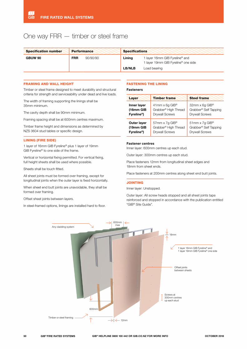
One way FRR — timber or steel frame
Specification number Performance Specifications
GBUW 90 FRR 90/90/90 Lining
LB/NLB
1 layer 16mm GIB Fyreline® and 1 layer 19mm GIB Fyreline® one side
Load bearing
FRAMING AND WALL HEIGHT
Timber or steel frame designed to meet durability and structural criteria for strength and serviceability under dead and live loads.
The width of framing supporting the linings shall be 35mm minimum.
The cavity depth shall be 90mm minimum.
Framing spacing shall be at 600mm centres maximum.
Timber frame height and dimensions as determined by NZS 3604 stud tables or specific design.
LINING (FIRE SIDE)
1 layer of 16mm GIB Fyreline® plus 1 layer of 19mm GIB Fyreline® to one side of the frame.
Vertical or horizontal fixing permitted. For vertical fixing, full height sheets shall be used where possible.
Sheets shall be touch fitted.
All sheet joints must be formed over framing, except for longitudinal joints when the outer layer is fixed horizontally.
When sheet end butt joints are unavoidable, they shall be formed over framing.
Offset sheet joints between layers.
In steel-framed options, linings are installed hard to floor.
FASTENING THE LINING
Fasteners
Layer Timber frame Steel frame
Inner layer (16mm GIBFyreline®)
41mm x 6g GIB® Grabber® High Thread Drywall Screws
32mm x 6g GIB® Grabber® Self Tapping Drywall Screws
Outer layer (19mm GIBFyreline®)
57mm x 7g GIB® Grabber® High Thread Drywall Screws
51mm x 7g GIB® Grabber® Self Tapping Drywall Screws
Fastener centres Inner layer: 600mm centres up each stud.
Outer layer: 300mm centres up each stud.
Place fasteners 12mm from longitudinal sheet edges and 18mm from sheet ends.
Place fasteners at 200mm centres along sheet end butt joints.
JOINTING
Inner layer: Unstopped.
Outer layer: All screw heads stopped and all sheet joints tape reinforced and stopped in accordance with the publication entitled “GIB® Site Guide”.
Screws at 300mm centres up each stud
Any cladding system
Timber or steel framing
600mm max
12mm
18mm
600mm
Offset joints between sheets
1 layer 16mm GIB Fyreline® and 1 layer 19mm GIB Fyreline® one side
50 GIB® FIRE RATED SYSTEMS GIB® HELPLINE 0800 100 442 OR GIB.CO.NZ FOR MORE INFO OCTOBER 2018
FIRE RATED WALL SYSTEMS
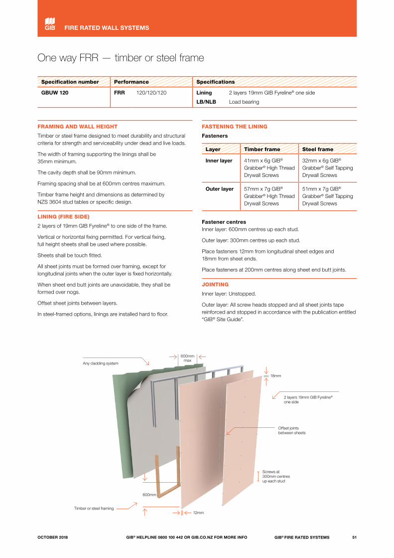
One way FRR — timber or steel frame
Specification number Performance Specifications
GBUW 120 FRR 120/120/120 Lining
LB/NLB
2 layers 19mm GIB Fyreline® one side
Load bearing
FRAMING AND WALL HEIGHT
Timber or steel frame designed to meet durability and structural criteria for strength and serviceability under dead and live loads.
The width of framing supporting the linings shall be 35mm minimum.
The cavity depth shall be 90mm minimum.
Framing spacing shall be at 600mm centres maximum.
Timber frame height and dimensions as determined by NZS 3604 stud tables or specific design.
LINING (FIRE SIDE)
2 layers of 19mm GIB Fyreline® to one side of the frame.
Vertical or horizontal fixing permitted. For vertical fixing, full height sheets shall be used where possible.
Sheets shall be touch fitted.
All sheet joints must be formed over framing, except for longitudinal joints when the outer layer is fixed horizontally.
When sheet end butt joints are unavoidable, they shall be formed over nogs.
Offset sheet joints between layers.
In steel-framed options, linings are installed hard to floor.
FASTENING THE LINING
Fasteners
Layer Timber frame Steel frame
Inner layer 41mm x 6g GIB® Grabber® High Thread Drywall Screws
32mm x 6g GIB® Grabber® Self Tapping Drywall Screws
Outer layer 57mm x 7g GIB® Grabber® High Thread Drywall Screws
51mm x 7g GIB® Grabber® Self Tapping Drywall Screws
Fastener centres Inner layer: 600mm centres up each stud.
Outer layer: 300mm centres up each stud.
Place fasteners 12mm from longitudinal sheet edges and 18mm from sheet ends.
Place fasteners at 200mm centres along sheet end butt joints.
JOINTING
Inner layer: Unstopped.
Outer layer: All screw heads stopped and all sheet joints tape reinforced and stopped in accordance with the publication entitled “GIB® Site Guide”.
Screws at 300mm centres up each stud
Any cladding system
Timber or steel framing
600mm max
12mm
18mm
600mm
Offset joints between sheets
2 layers 19mm GIB Fyreline® one side
51GIB® FIRE RATED SYSTEMSGIB® HELPLINE 0800 100 442 OR GIB.CO.NZ FOR MORE INFOOCTOBER 2018
FIRE RATED WALL SYSTEMS

Screws at 300mm centres up each stud
Any cladding system
Timber or steel framing12mm
600mm max
18mm
600mm
Offset joints between sheets
3 layers 19mm GIB Fyreline® one side
One way FRR — timber or steel frame
Specification number Performance Specifications
GBUW 180 FRR 180/180/180 Lining
LB/NLB
3 layers 19mm GIB Fyreline® one side
Load bearing
FRAMING AND WALL HEIGHT
Timber or steel frame designed to meet durability and structural criteria for strength and serviceability under dead and live loads.
The width of framing supporting the linings shall be 35mm minimum.
The cavity depth shall be 90mm minimum.
Framing spacing shall be at 600mm centres maximum.
Timber frame height and dimensions as determined by NZS 3604 stud tables or specific design.
LINING (FIRE SIDE)
3 layers of 19mm GIB Fyreline® to one side of the frame.
Vertical or horizontal fixing permitted. For vertical fixing, full height sheets shall be used where possible.
Sheets shall be touch fitted.
All sheet joints must be formed over framing, except for longitudinal joints when the outer layer is fixed horizontally.
When sheet end butt joints are unavoidable, they shall be formed over nogs.
Offset sheet joints between layers.
In steel-framed options, linings are installed hard to floor.
FASTENING THE LINING
Fasteners
Layer Timber frame Steel frame
Inner layer 41mm x 6g GIB® Grabber® High Thread Drywall Screws
32mm x 6g GIB® Grabber® Self Tapping Drywall Screws
Second layer 57mm x 7g GIB® Grabber® High Thread Drywall Screws
51mm x 7g GIB® Grabber® Self Tapping Drywall Screws
Third layer 76mm x 8g GIB® Grabber® Self Tapping Drywall Screws
76mm x 8g GIB® Grabber® Self Tapping Drywall Screws
Fastener centres Inner layer: 600mm centres up each stud.
Second and third layers: 300mm centres up each stud.
Place fasteners 12mm from longitudinal sheet edges and 18mm from sheet ends.
Place fasteners at 200mm centres along sheet end butt joints.
JOINTING
Inner layer: Unstopped.
Outer layer: All screw heads stopped and all sheet joints tape reinforced and stopped in accordance with the publication entitled “GIB® Site Guide”.
52 GIB® FIRE RATED SYSTEMS GIB® HELPLINE 0800 100 442 OR GIB.CO.NZ FOR MORE INFO OCTOBER 2018
FIRE RATED WALL SYSTEMS

53GIB® FIRE RATED SYSTEMSGIB® HELPLINE 0800 100 442 OR GIB.CO.NZ FOR MORE INFOOCTOBER 2018
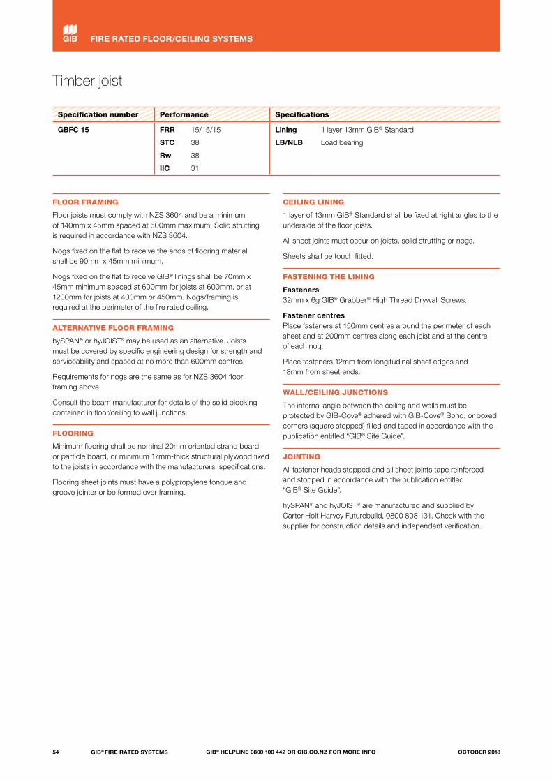
Timber joist
Specification number Performance Specifications
GBFC 15 FRR
STC
Rw
IIC
15/15/15
38
38
31
Lining
LB/NLB
1 layer 13mm GIB® Standard
Load bearing
FLOOR FRAMING
Floor joists must comply with NZS 3604 and be a minimum of 140mm x 45mm spaced at 600mm maximum. Solid strutting is required in accordance with NZS 3604.
Nogs fixed on the flat to receive the ends of flooring material shall be 90mm x 45mm minimum.
Nogs fixed on the flat to receive GIB® linings shall be 70mm x 45mm minimum spaced at 600mm for joists at 600mm, or at 1200mm for joists at 400mm or 450mm. Nogs/framing is required at the perimeter of the fire rated ceiling.
ALTERNATIVE FLOOR FRAMING
hySPAN® or hyJOIST® may be used as an alternative. Joists must be covered by specific engineering design for strength and serviceability and spaced at no more than 600mm centres.
Requirements for nogs are the same as for NZS 3604 floor framing above.
Consult the beam manufacturer for details of the solid blocking contained in floor/ceiling to wall junctions.
FLOORING
Minimum flooring shall be nominal 20mm oriented strand board or particle board, or minimum 17mm-thick structural plywood fixed to the joists in accordance with the manufacturers’ specifications.
Flooring sheet joints must have a polypropylene tongue and groove jointer or be formed over framing.
CEILING LINING
1 layer of 13mm GIB® Standard shall be fixed at right angles to the underside of the floor joists.
All sheet joints must occur on joists, solid strutting or nogs.
Sheets shall be touch fitted.
FASTENING THE LINING
Fasteners 32mm x 6g GIB® Grabber® High Thread Drywall Screws.
Fastener centres Place fasteners at 150mm centres around the perimeter of each sheet and at 200mm centres along each joist and at the centre of each nog.
Place fasteners 12mm from longitudinal sheet edges and 18mm from sheet ends.
WALL/CEILING JUNCTIONS
The internal angle between the ceiling and walls must be protected by GIB-Cove® adhered with GIB-Cove® Bond, or boxed corners (square stopped) filled and taped in accordance with the publication entitled “GIB® Site Guide”.
JOINTING
All fastener heads stopped and all sheet joints tape reinforced and stopped in accordance with the publication entitled “GIB® Site Guide”.
hySPAN® and hyJOIST® are manufactured and supplied by Carter Holt Harvey Futurebuild, 0800 808 131. Check with the supplier for construction details and independent verification.
54 GIB® FIRE RATED SYSTEMS GIB® HELPLINE 0800 100 442 OR GIB.CO.NZ FOR MORE INFO OCTOBER 2018
FIRE RATED FLOOR/CEILING SYSTEMS

Timber joist
Specification number Performance Specifications
GBFC 15 FRR
STC
Rw
IIC
15/15/15
38
38
31
Lining
LB/NLB
1 layer 13mm GIB® Standard
Load bearing
1 layer of 13mm GIB® Standard
70mm x 45mm nogs at 600mm centres
20mm HD particle board or 20mm oriented strand board or 17mm structural ply flooring
90mm x 45mm nogs
Perimeter fixing at 150mm centres
Single screws at 200mm centres across each joist
and to the centre of each nog
Min 140mm x 45mm timber joists
Solid strutting
600mm
55GIB® FIRE RATED SYSTEMSGIB® HELPLINE 0800 100 442 OR GIB.CO.NZ FOR MORE INFOOCTOBER 2018
FIRE RATED FLOOR/CEILING SYSTEMS
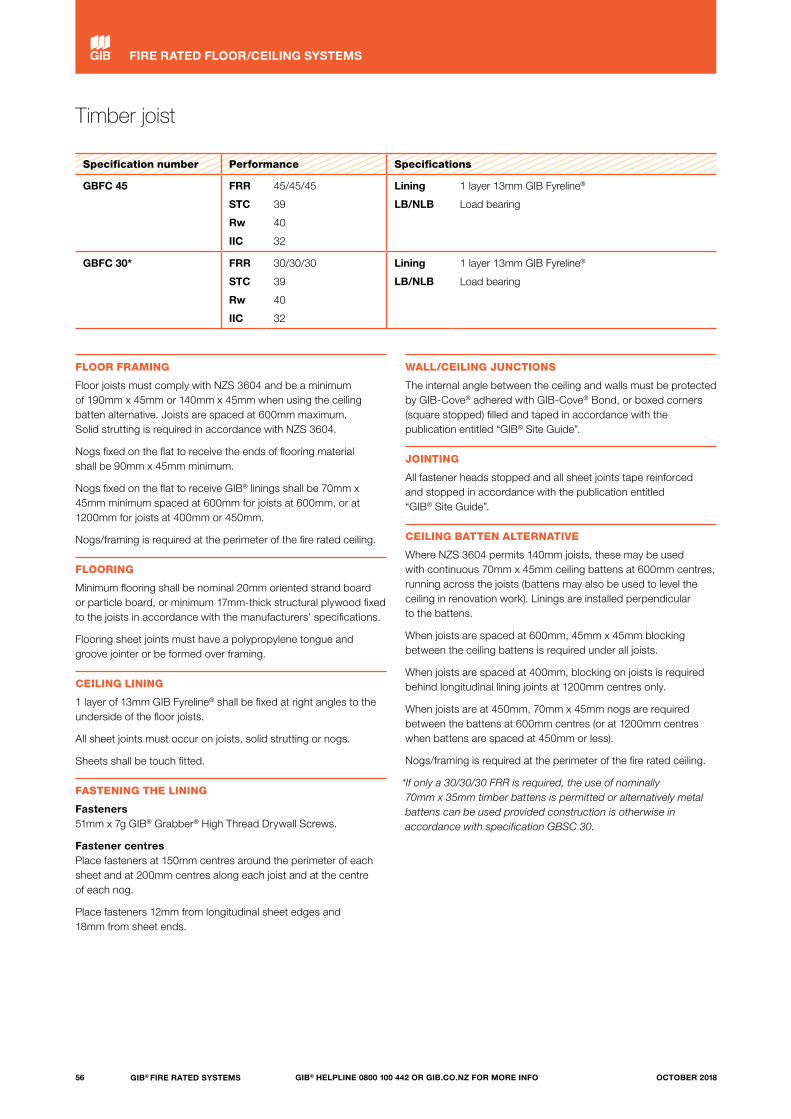
Timber joist
Specification number Performance Specifications
GBFC 45 FRR
STC
Rw
IIC
45/45/45
39
40
32
Lining
LB/NLB
1 layer 13mm GIB Fyreline®
Load bearing
GBFC 30* FRR
STC
Rw
IIC
30/30/30
39
40
32
Lining
LB/NLB
1 layer 13mm GIB Fyreline®
Load bearing
FLOOR FRAMING
Floor joists must comply with NZS 3604 and be a minimum of 190mm x 45mm or 140mm x 45mm when using the ceiling batten alternative. Joists are spaced at 600mm maximum. Solid strutting is required in accordance with NZS 3604.
Nogs fixed on the flat to receive the ends of flooring material shall be 90mm x 45mm minimum.
Nogs fixed on the flat to receive GIB® linings shall be 70mm x 45mm minimum spaced at 600mm for joists at 600mm, or at 1200mm for joists at 400mm or 450mm.
Nogs/framing is required at the perimeter of the fire rated ceiling.
FLOORING
Minimum flooring shall be nominal 20mm oriented strand board or particle board, or minimum 17mm-thick structural plywood fixed to the joists in accordance with the manufacturers’ specifications.
Flooring sheet joints must have a polypropylene tongue and groove jointer or be formed over framing.
CEILING LINING
1 layer of 13mm GIB Fyreline® shall be fixed at right angles to the underside of the floor joists.
All sheet joints must occur on joists, solid strutting or nogs.
Sheets shall be touch fitted.
FASTENING THE LINING
Fasteners 51mm x 7g GIB® Grabber® High Thread Drywall Screws.
Fastener centres Place fasteners at 150mm centres around the perimeter of each sheet and at 200mm centres along each joist and at the centre of each nog.
Place fasteners 12mm from longitudinal sheet edges and 18mm from sheet ends.
WALL/CEILING JUNCTIONS
The internal angle between the ceiling and walls must be protected by GIB-Cove® adhered with GIB-Cove® Bond, or boxed corners (square stopped) filled and taped in accordance with the publication entitled “GIB® Site Guide”.
JOINTING
All fastener heads stopped and all sheet joints tape reinforced and stopped in accordance with the publication entitled “GIB® Site Guide”.
CEILING BATTEN ALTERNATIVE
Where NZS 3604 permits 140mm joists, these may be used with continuous 70mm x 45mm ceiling battens at 600mm centres, running across the joists (battens may also be used to level the ceiling in renovation work). Linings are installed perpendicular to the battens.
When joists are spaced at 600mm, 45mm x 45mm blocking between the ceiling battens is required under all joists.
When joists are spaced at 400mm, blocking on joists is required behind longitudinal lining joints at 1200mm centres only.
When joists are at 450mm, 70mm x 45mm nogs are required between the battens at 600mm centres (or at 1200mm centres when battens are spaced at 450mm or less).
Nogs/framing is required at the perimeter of the fire rated ceiling.
*If only a 30/30/30 FRR is required, the use of nominally 70mm x 35mm timber battens is permitted or alternatively metal battens can be used provided construction is otherwise in accordance with specification GBSC 30.
56 GIB® FIRE RATED SYSTEMS GIB® HELPLINE 0800 100 442 OR GIB.CO.NZ FOR MORE INFO OCTOBER 2018
FIRE RATED FLOOR/CEILING SYSTEMS

Timber joist
Specification number Performance Specifications
GBFC 45 FRR
STC
Rw
IIC
45/45/45
39
40
32
Lining
LB/NLB
1 layer 13mm GIB Fyreline®
Load bearing
GBFC 30* FRR
STC
Rw
IIC
30/30/30
39
40
32
Lining
LB/NLB
1 layer 13mm GIB Fyreline®
Load bearing
CEILING BATTEN ALTERNATIVE
1 layer of 13mm GIB Fyreline®
70mm x 45mm nogs at 600mm centres
70mm x 45mm ceiling battens, running across joists at 600mm centres maximum
20mm HD particle board or 20mm oriented strand board or 17mm structural ply flooring
90mm x 45mm nogs
140mm x 45mm timber joists
Perimeter fixing at 150mm centres
Single screws at 200mm centres across each joist
and to the centre of each nog
Min 190mm x 45mm timber joists
45mm x 45mm blocking on joists
600mm
Solid strutting
57GIB® FIRE RATED SYSTEMSGIB® HELPLINE 0800 100 442 OR GIB.CO.NZ FOR MORE INFOOCTOBER 2018
FIRE RATED FLOOR/CEILING SYSTEMS
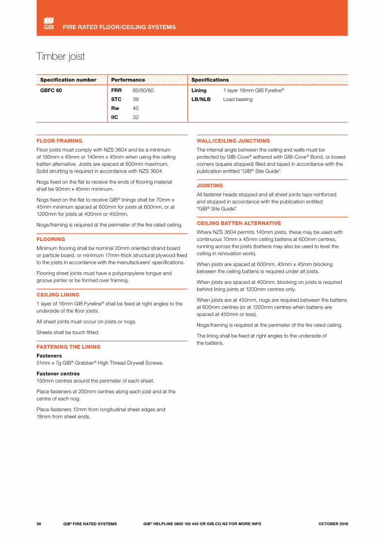
Timber joist
Specification number Performance Specifications
GBFC 60 FRR
STC
Rw
IIC
60/60/60
39
40
32
Lining
LB/NLB
1 layer 16mm GIB Fyreline®
Load bearing
FLOOR FRAMING
Floor joists must comply with NZS 3604 and be a minimum of 190mm x 45mm or 140mm x 45mm when using the ceiling batten alternative. Joists are spaced at 600mm maximum. Solid strutting is required in accordance with NZS 3604.
Nogs fixed on the flat to receive the ends of flooring material shall be 90mm x 45mm minimum.
Nogs fixed on the flat to receive GIB® linings shall be 70mm x 45mm minimum spaced at 600mm for joists at 600mm, or at 1200mm for joists at 400mm or 450mm.
Nogs/framing is required at the perimeter of the fire rated ceiling.
FLOORING
Minimum flooring shall be nominal 20mm oriented strand board or particle board, or minimum 17mm-thick structural plywood fixed to the joists in accordance with the manufacturers’ specifications.
Flooring sheet joints must have a polypropylene tongue and groove jointer or be formed over framing.
CEILING LINING
1 layer of 16mm GIB Fyreline® shall be fixed at right angles to the underside of the floor joists.
All sheet joints must occur on joists or nogs.
Sheets shall be touch fitted.
FASTENING THE LINING
Fasteners 51mm x 7g GIB® Grabber® High Thread Drywall Screws.
Fastener centres 150mm centres around the perimeter of each sheet.
Place fasteners at 200mm centres along each joist and at the centre of each nog.
Place fasteners 12mm from longitudinal sheet edges and 18mm from sheet ends.
WALL/CEILING JUNCTIONS
The internal angle between the ceiling and walls must be protected by GIB-Cove® adhered with GIB-Cove® Bond, or boxed corners (square stopped) filled and taped in accordance with the publication entitled “GIB® Site Guide”.
JOINTING
All fastener heads stopped and all sheet joints tape reinforced and stopped in accordance with the publication entitled “GIB® Site Guide”.
CEILING BATTEN ALTERNATIVE
Where NZS 3604 permits 140mm joists, these may be used with continuous 70mm x 45mm ceiling battens at 600mm centres, running across the joists (battens may also be used to level the ceiling in renovation work).
When joists are spaced at 600mm, 45mm x 45mm blocking between the ceiling battens is required under all joists.
When joists are spaced at 400mm, blocking on joists is required behind lining joints at 1200mm centres only.
When joists are at 450mm, nogs are required between the battens at 600mm centres (or at 1200mm centres when battens are spaced at 450mm or less).
Nogs/framing is required at the perimeter of the fire rated ceiling.
The lining shall be fixed at right angles to the underside of the battens.
58 GIB® FIRE RATED SYSTEMS GIB® HELPLINE 0800 100 442 OR GIB.CO.NZ FOR MORE INFO OCTOBER 2018
FIRE RATED FLOOR/CEILING SYSTEMS
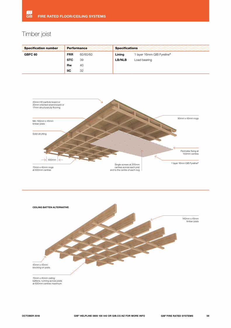
Timber joist
Specification number Performance Specifications
GBFC 60 FRR
STC
Rw
IIC
60/60/60
39
40
32
Lining
LB/NLB
1 layer 16mm GIB Fyreline®
Load bearing
CEILING BATTEN ALTERNATIVE
1 layer 16mm GIB Fyreline®
70mm x 45mm nogs at 600mm centres
70mm x 45mm ceiling battens, running across joists at 600mm centres maximum
20mm HD particle board or 20mm oriented strand board or 17mm structural ply flooring
90mm x 45mm nogs
140mm x 45mm timber joists
Perimeter fixing at 150mm centres
Single screws at 200mm centres across each joist
and to the centre of each nog
45mm x 45mm blocking on joists
600mm
Min 190mm x 45mm timber joists
Solid strutting
59GIB® FIRE RATED SYSTEMSGIB® HELPLINE 0800 100 442 OR GIB.CO.NZ FOR MORE INFOOCTOBER 2018
FIRE RATED FLOOR/CEILING SYSTEMS

Timber joist
Specification number Performance Specifications
GBFC 90 FRR
STC
Rw
IIC
90/90/90
41
41
34
Lining
LB/NLB
2 layers 16mm GIB Fyreline®
Load bearing
FLOOR FRAMING
Floor joists must comply with NZS 3604 and be a minimum of 190mm x 45mm spaced at 400mm maximum. Solid strutting is required at 1800mm centres.
Nogs fixed on the flat to receive the ends of flooring material shall be 90mm x 45mm minimum.
Nogs fixed on the flat to receive GIB® linings shall be 70mm x 45mm minimum spaced at 600mm centres.
Nogs/framing is required at the perimeter of the fire rated ceiling.
FLOORING
Minimum flooring shall be nominal 20mm oriented strand board or particle board, or minimum 17mm-thick structural plywood fixed to the joists in accordance with the manufacturers’ specifications.
Flooring sheet joints must have a polypropylene tongue and groove jointer or be formed over framing.
CEILING LINING
2 layers of 16mm GIB Fyreline® shall be fixed at right angles to the underside of the floor joists. The sheet joints of the second layer are to be offset from those of the first layer.
All sheet joints must occur on joists, solid strutting or nogs.
Sheets shall be touch fitted.
FASTENING THE LINING
Fasteners Inner layer: 51mm x 7g GIB® Grabber® High Thread Drywall Screws.
Outer layer: 76mm x 8g GIB® Grabber® Self Tapping Drywall Screws.
Fastener centres Inner layer: Place fasteners at 150mm centres around the perimeter of each sheet, across each joist and at the centre of each nog.
Outer layer: Place fasteners at 150mm centres around the perimeter of each sheet, across each joist and at the centre of each nog.
Place fasteners 12mm from longitudinal sheet edges and 18mm from sheet ends.
WALL/CEILING JUNCTIONS
The internal angle between the ceiling and walls must be protected by GIB-Cove® adhered with GIB-Cove® Bond, or boxed corners (square stopped) filled and taped in accordance with the publication entitled “GIB® Site Guide”.
JOINTING
Inner layer: Unstopped.
Outer layer: All fastener heads stopped and all sheet joints tape reinforced and stopped in accordance with the publication entitled “GIB® Site Guide”.
CEILING BATTEN ALTERNATIVE
Where NZS 3604 permits 140mm joists, these may be used with continuous 70mm x 45mm ceiling battens at 600mm centres, running across the joists (battens may also be used to level the ceiling in renovation work).
45mm x 45mm blocking between the ceiling battens is required under all joists.
Nogs/framing is required at the perimeter of the fire rated ceiling.
The lining shall be fixed at right angles to the underside of the battens.
The joints of the outer layer are to be offset from those of the inner layer.
60 GIB® FIRE RATED SYSTEMS GIB® HELPLINE 0800 100 442 OR GIB.CO.NZ FOR MORE INFO OCTOBER 2018
FIRE RATED FLOOR/CEILING SYSTEMS
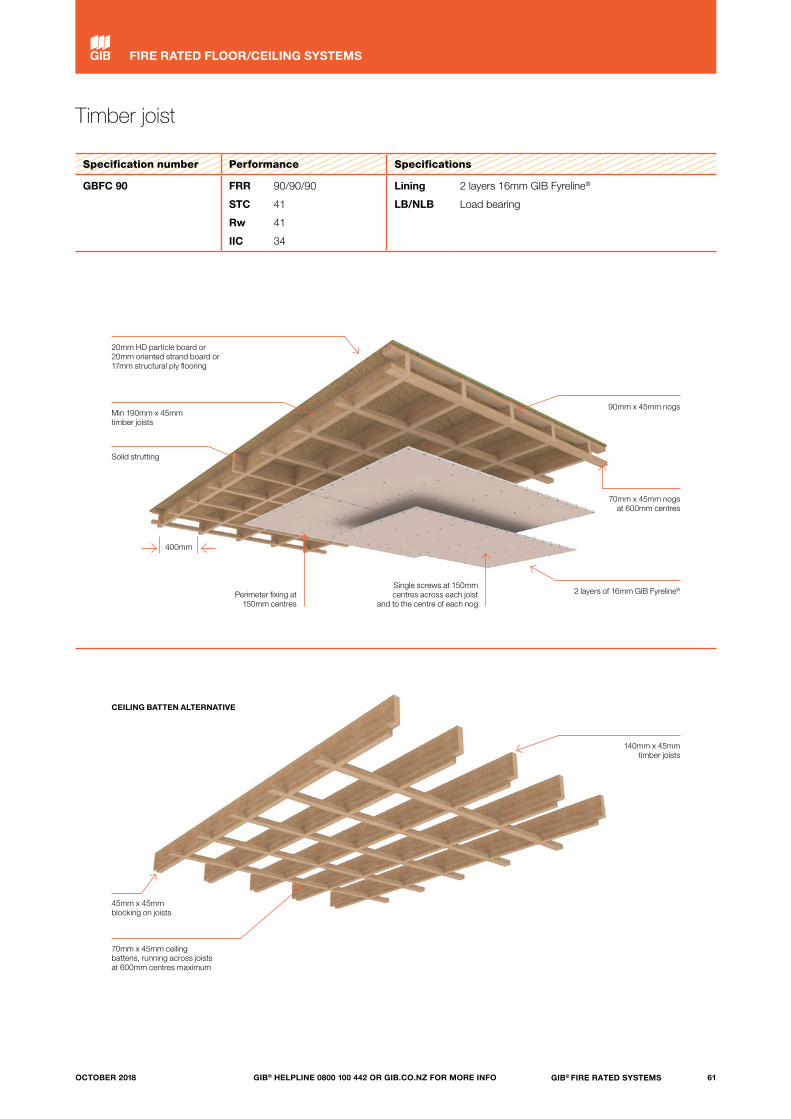
Timber joist
Specification number Performance Specifications
GBFC 90 FRR
STC
Rw
IIC
90/90/90
41
41
34
Lining
LB/NLB
2 layers 16mm GIB Fyreline®
Load bearing
CEILING BATTEN ALTERNATIVE
2 layers of 16mm GIB Fyreline®
70mm x 45mm ceiling battens, running across joists at 600mm centres maximum
20mm HD particle board or 20mm oriented strand board or 17mm structural ply flooring
90mm x 45mm nogs
140mm x 45mm timber joists
70mm x 45mm nogs at 600mm centres
Single screws at 150mm centres across each joist
and to the centre of each nogPerimeter fixing at
150mm centres
45mm x 45mm blocking on joists
400mm
Min 190mm x 45mm timber joists
Solid strutting
61GIB® FIRE RATED SYSTEMSGIB® HELPLINE 0800 100 442 OR GIB.CO.NZ FOR MORE INFOOCTOBER 2018
FIRE RATED FLOOR/CEILING SYSTEMS
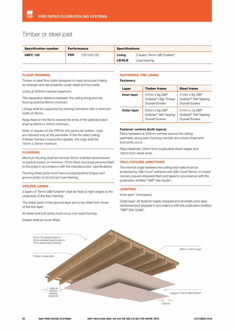
Timber or steel joist
Specification number Performance Specifications
GBFC 120 FRR 120/120/120 Lining
LB/NLB
2 layers 19mm GIB Fyreline®
Load bearing
FLOOR FRAMING
Timber or steel floor joists designed to meet structural criteria for strength and serviceability under dead and live loads.
Joists at 500mm centres maximum.
The separation distance between the ceiling lining and the flooring shall be 90mm minimum.
Linings shall be supported by framing members with a minimum width of 35mm.
Nogs fixed on the flat to receive the ends of the particle board shall be 90mm x 45mm minimum.
Note: In respect of the FRR for this particular system, nogs are required only at the perimeter of the fire rated ceiling. If timber-framed construction applies, the nogs shall be 70mm x 35mm minimum.
FLOORING
Minimum flooring shall be nominal 20mm oriented strand board or particle board, or minimum 17mm-thick structural plywood fixed to the joists in accordance with the manufacturers’ specifications.
Flooring sheet joints must have a polypropylene tongue and groove jointer or be formed over framing.
CEILING LINING
2 layers of 19mm GIB Fyreline® shall be fixed at right angles to the underside of the floor framing.
The sheet joints of the second layer are to be offset from those of the first layer.
All sheet end butt joints must occur over solid framing.
Sheets shall be touch fitted.
FASTENING THE LINING
Fasteners
Layer Timber frame Steel frame
Inner layer 41mm x 6g GIB® Grabber® High Thread Drywall Screws
41mm x 6g GIB® Grabber® Self Tapping Drywall Screws
Outer layer 63mm x 8g GIB® Grabber® Self Tapping Drywall Screws
51mm x 7g GIB® Grabber® Self Tapping Drywall Screws
Fastener centres (both layers) Place fasteners at 200mm centres around the ceiling perimeter, along each framing member and where sheet end butt joints occur.
Place fasteners 12mm from longitudinal sheet edges and 18mm from sheet ends.
WALL/CEILING JUNCTIONS
The internal angle between the ceiling and walls must be protected by GIB-Cove® adhered with GIB-Cove® Bond, or boxed corners (square stopped) filled and taped in accordance with the publication entitled “GIB® Site Guide”.
JOINTING
Inner layer: Unstopped.
Outer layer: All fastener heads stopped and all sheet joints tape reinforced and stopped in accordance with the publication entitled “GIB® Site Guide”.
2 layers of 19mm GIB Fyreline®
20mm HD particle board or 20mm oriented strand board or 17mm structural ply flooring
Timber or steel joists
90mm x 45mm nogs
Joists at 500mmcentres
maximum
200mm
62 GIB® FIRE RATED SYSTEMS GIB® HELPLINE 0800 100 442 OR GIB.CO.NZ FOR MORE INFO OCTOBER 2018
FIRE RATED FLOOR/CEILING SYSTEMS

Composite joist
Specification number Performance Specifications
GBCJ 45 FRR
STC
Rw
IIC
45/45/45
39
40
32
Lining
LB/NLB
1 layer 13mm GIB Fyreline®
Load bearing
GBCJ 30* FRR
STC
Rw
IIC
30/30/30
39
40
32
Lining
LB/NLB
1 layer 13mm GIB Fyreline®
Load bearing
FLOOR FRAMING FASTENING THE LINING
Floor joists may be either hySPAN® or hyJOIST®.
Joists shall be covered by specific engineering design for strength and serviceability, have a depth no less than 190mm and spacing no more than 600mm.
Nogs fixed on the flat to receive the ends of flooring material shall be 90mm x 45mm minimum.
Nogs fixed on the flat to receive GIB® linings shall be 70mm x 45mm minimum spaced at 600mm for joists at 600mm, or at 1200mm for joists at 400mm or 450mm.
Nogs/framing is required at the perimeter of the fire rated ceiling.
Consult the beam manufacturer re construction of the solid blocking contained in floor/ceiling to wall junctions.
FLOORING
Minimum flooring shall be nominal 20mm oriented strand board or particle board, or minimum 17mm-thick structural plywood fixed to the joists in accordance with the manufacturers’ specifications.
Flooring sheet joints must have a polypropylene tongue and groove jointer or be formed over framing.
CEILING LINING
1 layer of 13mm GIB Fyreline® shall be fixed at right angles to the underside of the floor joists.
All sheet joints must occur on joists or nogs.
Sheets shall be touch fitted.
FASTENING THE LINING
Fasteners 51mm x 7g GIB® Grabber® High Thread Drywall Screws.
Fastener centres Place fasteners at 150mm centres around the perimeter of each sheet and at 200mm centres along each joist and at the centre of each nog.
Place fasteners 12mm from longitudinal sheet edges and 18mm from sheet ends.
WALL/CEILING JUNCTIONS
The internal angle between the ceiling and walls must be protected by GIB-Cove® adhered with GIB-Cove® Bond, or boxed corners (square stopped) filled and taped in accordance with the publication entitled “GIB® Site Guide”.
JOINTING
All fastener heads stopped and all sheet joints tape reinforced and stopped in accordance with the publication entitled “GIB® Site Guide”.
hySPAN® and hyJOIST® are manufactured and supplied by Carter Holt Harvey Futurebuild, 0800 808 131. Check with the supplier for construction details and independent verification.
CEILING BATTENS
*If only a 30/30/30 FRR is required, the use of nominally 70mm x 35mm timber battens is permitted or alternatively metal battens can be used provided construction is otherwise in accordance with specification GBSC 30.
1 layer of 13mm GIB Fyreline®70mm x 45mm nogs at 600mm centres
20mm HD particle board or 20mm strand board or 17mm structural ply flooring
90mm x 45mm nogs
Perimeter fixing at 150mm centres
Single screws at 200mm centres across each joist
and to the centre of each nog
Min 190mm x 45mm composite joists
600mm
63GIB® FIRE RATED SYSTEMSGIB® HELPLINE 0800 100 442 OR GIB.CO.NZ FOR MORE INFOOCTOBER 2018
FIRE RATED FLOOR/CEILING SYSTEMS
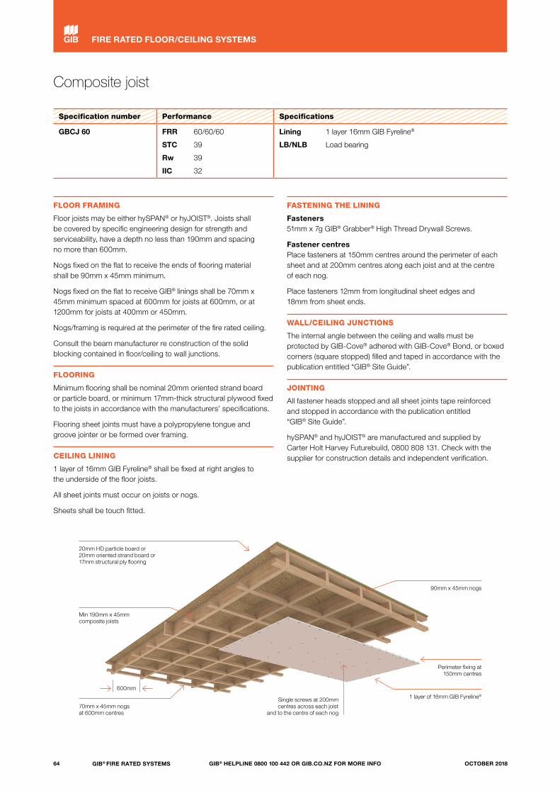
Composite joist
Specification number Performance Specifications
GBCJ 60 FRR
STC
Rw
IIC
60/60/60
39
39
32
Lining
LB/NLB
1 layer 16mm GIB Fyreline®
Load bearing
FLOOR FRAMING
Floor joists may be either hySPAN® or hyJOIST®. Joists shall be covered by specific engineering design for strength and serviceability, have a depth no less than 190mm and spacing no more than 600mm.
Nogs fixed on the flat to receive the ends of flooring material shall be 90mm x 45mm minimum.
Nogs fixed on the flat to receive GIB® linings shall be 70mm x 45mm minimum spaced at 600mm for joists at 600mm, or at 1200mm for joists at 400mm or 450mm.
Nogs/framing is required at the perimeter of the fire rated ceiling.
Consult the beam manufacturer re construction of the solid blocking contained in floor/ceiling to wall junctions.
FLOORING
Minimum flooring shall be nominal 20mm oriented strand board or particle board, or minimum 17mm-thick structural plywood fixed to the joists in accordance with the manufacturers’ specifications.
Flooring sheet joints must have a polypropylene tongue and groove jointer or be formed over framing.
CEILING LINING
1 layer of 16mm GIB Fyreline® shall be fixed at right angles to the underside of the floor joists.
All sheet joints must occur on joists or nogs.
Sheets shall be touch fitted.
FASTENING THE LINING
Fasteners 51mm x 7g GIB® Grabber® High Thread Drywall Screws.
Fastener centres Place fasteners at 150mm centres around the perimeter of each sheet and at 200mm centres along each joist and at the centre of each nog.
Place fasteners 12mm from longitudinal sheet edges and 18mm from sheet ends.
WALL/CEILING JUNCTIONS
The internal angle between the ceiling and walls must be protected by GIB-Cove® adhered with GIB-Cove® Bond, or boxed corners (square stopped) filled and taped in accordance with the publication entitled “GIB® Site Guide”.
JOINTING
All fastener heads stopped and all sheet joints tape reinforced and stopped in accordance with the publication entitled “GIB® Site Guide”.
hySPAN® and hyJOIST® are manufactured and supplied by Carter Holt Harvey Futurebuild, 0800 808 131. Check with the supplier for construction details and independent verification.
1 layer of 16mm GIB Fyreline®
70mm x 45mm nogs at 600mm centres
20mm HD particle board or 20mm oriented strand board or 17mm structural ply flooring
90mm x 45mm nogs
Perimeter fixing at 150mm centres
Single screws at 200mm centres across each joist
and to the centre of each nog
Min 190mm x 45mm composite joists
600mm
64 GIB® FIRE RATED SYSTEMS GIB® HELPLINE 0800 100 442 OR GIB.CO.NZ FOR MORE INFO OCTOBER 2018
FIRE RATED FLOOR/CEILING SYSTEMS
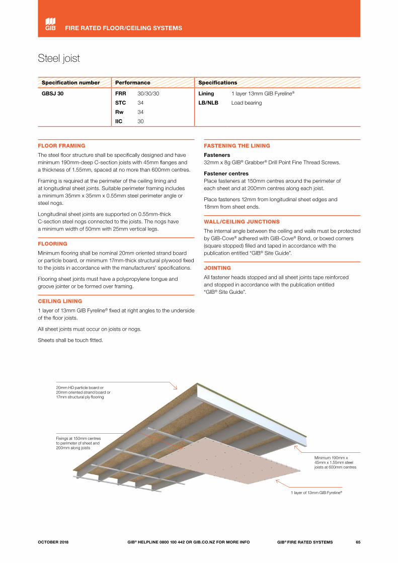
Steel joist
Specification number Performance Specifications
GBSJ 30 FRR
STC
Rw
IIC
30/30/30
34
34
30
Lining
LB/NLB
1 layer 13mm GIB Fyreline®
Load bearing
FLOOR FRAMING
The steel floor structure shall be specifically designed and have minimum 190mm-deep C-section joists with 45mm flanges and a thickness of 1.55mm, spaced at no more than 600mm centres.
Framing is required at the perimeter of the ceiling lining and at longitudinal sheet joints. Suitable perimeter framing includes a minimum 35mm x 35mm x 0.55mm steel perimeter angle or steel nogs.
Longitudinal sheet joints are supported on 0.55mm-thick C-section steel nogs connected to the joists. The nogs have a minimum width of 50mm with 25mm vertical legs.
FLOORING
Minimum flooring shall be nominal 20mm oriented strand board or particle board, or minimum 17mm-thick structural plywood fixed to the joists in accordance with the manufacturers’ specifications.
Flooring sheet joints must have a polypropylene tongue and groove jointer or be formed over framing.
CEILING LINING
1 layer of 13mm GIB Fyreline® fixed at right angles to the underside of the floor joists.
All sheet joints must occur on joists or nogs.
Sheets shall be touch fitted.
FASTENING THE LINING
Fasteners 32mm x 8g GIB® Grabber® Drill Point Fine Thread Screws.
Fastener centres Place fasteners at 150mm centres around the perimeter of each sheet and at 200mm centres along each joist.
Place fasteners 12mm from longitudinal sheet edges and 18mm from sheet ends.
WALL/CEILING JUNCTIONS
The internal angle between the ceiling and walls must be protected by GIB-Cove® adhered with GIB-Cove® Bond, or boxed corners (square stopped) filled and taped in accordance with the publication entitled “GIB® Site Guide”.
JOINTING
All fastener heads stopped and all sheet joints tape reinforced and stopped in accordance with the publication entitled “GIB® Site Guide”.
1 layer of 13mm GIB Fyreline®
Minimum 190mm x 45mm x 1.55mm steel joists at 600mm centres
20mm HD particle board or 20mm oriented strand board or 17mm structural ply flooring
Fixings at 150mm centres to perimeter of sheet and 200mm along joists
65GIB® FIRE RATED SYSTEMSGIB® HELPLINE 0800 100 442 OR GIB.CO.NZ FOR MORE INFOOCTOBER 2018
FIRE RATED FLOOR/CEILING SYSTEMS
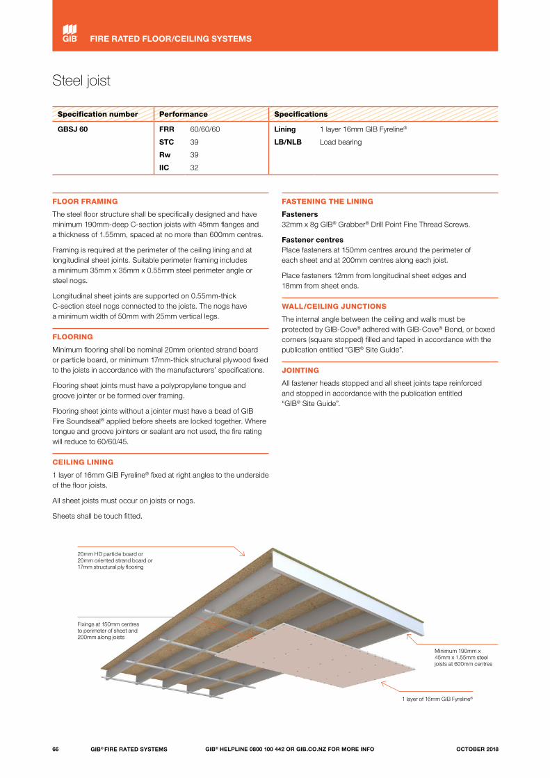
Steel joist
Specification number Performance Specifications
GBSJ 60 FRR
STC
Rw
IIC
60/60/60
39
39
32
Lining
LB/NLB
1 layer 16mm GIB Fyreline®
Load bearing
FLOOR FRAMING
The steel floor structure shall be specifically designed and have minimum 190mm-deep C-section joists with 45mm flanges and a thickness of 1.55mm, spaced at no more than 600mm centres.
Framing is required at the perimeter of the ceiling lining and at longitudinal sheet joints. Suitable perimeter framing includes a minimum 35mm x 35mm x 0.55mm steel perimeter angle or steel nogs.
Longitudinal sheet joints are supported on 0.55mm-thick C-section steel nogs connected to the joists. The nogs have a minimum width of 50mm with 25mm vertical legs.
FLOORING
Minimum flooring shall be nominal 20mm oriented strand board or particle board, or minimum 17mm-thick structural plywood fixed to the joists in accordance with the manufacturers’ specifications.
Flooring sheet joints must have a polypropylene tongue and groove jointer or be formed over framing.
Flooring sheet joints without a jointer must have a bead of GIB Fire Soundseal® applied before sheets are locked together. Where tongue and groove jointers or sealant are not used, the fire rating will reduce to 60/60/45.
CEILING LINING
1 layer of 16mm GIB Fyreline® fixed at right angles to the underside of the floor joists.
All sheet joists must occur on joists or nogs.
Sheets shall be touch fitted.
FASTENING THE LINING
Fasteners 32mm x 8g GIB® Grabber® Drill Point Fine Thread Screws.
Fastener centres Place fasteners at 150mm centres around the perimeter of each sheet and at 200mm centres along each joist.
Place fasteners 12mm from longitudinal sheet edges and 18mm from sheet ends.
WALL/CEILING JUNCTIONS
The internal angle between the ceiling and walls must be protected by GIB-Cove® adhered with GIB-Cove® Bond, or boxed corners (square stopped) filled and taped in accordance with the publication entitled “GIB® Site Guide”.
JOINTING
All fastener heads stopped and all sheet joints tape reinforced and stopped in accordance with the publication entitled “GIB® Site Guide”.
1 layer of 16mm GIB Fyreline®
Minimum 190mm x 45mm x 1.55mm steel joists at 600mm centres
20mm HD particle board or 20mm oriented strand board or 17mm structural ply flooring
Fixings at 150mm centres to perimeter of sheet and 200mm along joists
66 GIB® FIRE RATED SYSTEMS GIB® HELPLINE 0800 100 442 OR GIB.CO.NZ FOR MORE INFO OCTOBER 2018
FIRE RATED FLOOR/CEILING SYSTEMS

Suspended grid
Specification number Performance Specifications
GBSC 30 FRR
STC
Rw
IIC
30/30/30
48
47
43
Lining
LB/NLB
1 layer 13mm GIB Fyreline® (back-blocked)
Load bearing
FLOOR FRAMING
Timber floor joists complying with NZS 3604 spaced at 600mm centres maximum.
Alternatively, a proprietary I-joist system may be used subject to specific structural design and approval by the normal building consent process.
FLOORING
Minimum flooring shall be nominal 20mm oriented strand board or particle board, or minimum 17mm-thick structural plywood fixed to the joists in accordance with the manufacturers’ specifications.
Flooring sheet joints must have a polypropylene tongue and groove jointer or be formed over framing.
SUSPENSION SYSTEM
Rondo® KEY-LOCK™ steel frame suspension system comprising 2.5mm wire hangers at 1200mm centres supporting top cross rails (part 128) spaced at 1200mm centres and furring channels (part 129) spaced at 600mm centres maximum.
Rondo Donn® ScrewFix™ steel frame suspension system comprising 2.5mm wire hangers at 1200mm centres supporting F38 strongback channels spaced at 1200mm centres and F37 furring channels spaced at 600mm centres maximum.
Direct or clip fixed GIB® Rondo® Ceiling Batten system with full perimeter channel supports.
Note: Suspension system must be installed in accordance with manufacturer’s specification.
CEILING LINING
1 layer of 13mm GIB Fyreline® shall be fixed at right angles to the underside of the furring channels.
All sheet end butt joints must occur on the furring channels.
Sheets shall be touch fitted.
Joints formed by sheet edges shall be back-blocked between the furring channels with strips of 13mm GIB Fyreline®.
The width of the back-blocks shall be 300mm minimum and shall be adhered with GIB-Cove® Bond.
FASTENING THE LINING
Fasteners 25mm x 6g GIB® Grabber® Self Tapping Drywall Screws.
Fastener centres Place fasteners 12mm from longitudinal sheet edges and 18mm from sheet ends. This distance may be reduced to 12mm from sheet ends at butt joints on furring channels.
Place fasteners at 200mm centres along each intermediate furring channel, around the ceiling perimeter and where sheet end butt joints occur.
WALL/CEILING JUNCTIONS
The internal angle between the ceiling and walls must be protected by GIB-Cove® adhered with GIB-Cove® Bond, or boxed corners (square stopped) filled and taped in accordance with the publication entitled “GIB® Site Guide”.
JOINTING
All fastener heads stopped and all sheet joints tape reinforced and stopped in accordance with the publication entitled “GIB Site Guide”.
20mm HD particle board or 20mm oriented strand board or 17mm structural ply flooring
Back-blocking 300mm width
1 layer of 13mm GIB Fyreline® (back-blocked)
Timber joists at 600mm centres
maximum
Rondo® KEY-LOCK™ or Rondo Donn®
ScrewFix™ steel frame suspension system
600mm
200mm
67GIB® FIRE RATED SYSTEMSGIB® HELPLINE 0800 100 442 OR GIB.CO.NZ FOR MORE INFOOCTOBER 2018
FIRE RATED FLOOR/CEILING SYSTEMS
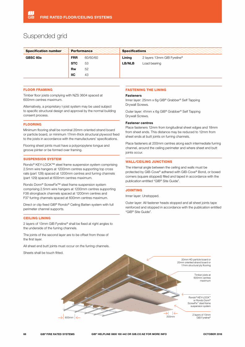
20mm HD particle board or 20mm oriented strand board or
17mm structural ply flooring
Suspended grid
Specification number Performance Specifications
GBSC 60a FRR
STC
Rw
IIC
60/60/60
53
52
43
Lining
LB/NLB
2 layers 13mm GIB Fyreline®
Load bearing
FLOOR FRAMING
Timber floor joists complying with NZS 3604 spaced at 600mm centres maximum.
Alternatively, a proprietary I-joist system may be used subject to specific structural design and approval by the normal building consent process.
FLOORING
Minimum flooring shall be nominal 20mm oriented strand board or particle board, or minimum 17mm-thick structural plywood fixed to the joists in accordance with the manufacturers’ specifications.
Flooring sheet joints must have a polypropylene tongue and groove jointer or be formed over framing.
SUSPENSION SYSTEM
Rondo® KEY-LOCK™ steel frame suspension system comprising 2.5mm wire hangers at 1200mm centres supporting top cross rails (part 128) spaced at 1200mm centres and furring channels (part 129) spaced at 600mm centres maximum.
Rondo Donn® ScrewFix™ steel frame suspension system comprising 2.5mm wire hangers at 1200mm centres supporting F38 strongback channels spaced at 1200mm centres and F37 furring channels spaced at 600mm centres maximum.
Direct or clip fixed GIB® Rondo® Ceiling Batten system with full perimeter channel supports.
CEILING LINING
2 layers of 13mm GIB Fyreline® shall be fixed at right angles to the underside of the furring channels.
The joints of the second layer are to be offset from those of the first layer.
All sheet end butt joints must occur on the furring channels.
Sheets shall be touch fitted.
FASTENING THE LINING
Fasteners Inner layer: 25mm x 6g GIB® Grabber® Self Tapping Drywall Screws.
Outer layer: 41mm x 6g GIB® Grabber® Self Tapping Drywall Screws.
Fastener centres Place fasteners 12mm from longitudinal sheet edges and 18mm from sheet ends. This distance may be reduced to 12mm from sheet ends at butt joints on furring channels.
Place fasteners at 200mm centres along each intermediate furring channel, around the ceiling perimeter and where sheet end butt joints occur.
WALL/CEILING JUNCTIONS
The internal angle between the ceiling and walls must be protected by GIB-Cove® adhered with GIB-Cove® Bond, or boxed corners (square stopped) filled and taped in accordance with the publication entitled “GIB® Site Guide”.
JOINTING
Inner layer: Unstopped.
Outer layer: All fastener heads stopped and all sheet joints tape reinforced and stopped in accordance with the publication entitled “GIB® Site Guide”.
2 layers of 13mm GIB Fyreline®
Timber joists at 600mm centres
maximum
600mm 200mm
Rondo® KEY-LOCK™ or Rondo Donn®
ScrewFix™ steel frame suspension system
68 GIB® FIRE RATED SYSTEMS GIB® HELPLINE 0800 100 442 OR GIB.CO.NZ FOR MORE INFO OCTOBER 2018
FIRE RATED FLOOR/CEILING SYSTEMS

Suspended grid
Specification number Performance Specifications
GBSC 60b FRR
STC
Rw
IIC
60/60/60
50
49
43
Lining
LB/NLB
1 layer 16mm GIB Fyreline®
Load bearing
FLOOR FRAMING
Timber floor joists complying with NZS 3604 spaced at 600mm centres maximum.
Alternatively, a proprietary I-joist system may be used subject to specific structural design and approval by the normal building consent process.
FLOORING
Minimum flooring shall be nominal 20mm oriented strand board or particle board, or minimum 17mm-thick structural plywood fixed to the joists in accordance with the manufacturers’ specifications.
Flooring sheet joints must have a polypropylene tongue and groove jointer or be formed over framing.
SUSPENSION SYSTEM
Rondo Xpress® Drywall Grid Ceiling System comprising 2.5mm wire hangers or XD50 wall angles at 1200mm centres maximum. Hangers support XD24 main tee at 1200mm centres maximum. XD21200 cross tees installed at 600mm centres. Install XD20600 cross tees at 1200mm centres, parallel with the main tee.
The distance between the underside of the flooring and the top of the ceiling linings shall be a minimum of 450mm.
Note: Suspension system must be installed in accordance with manufacturer’s specification.
CEILING LINING
1 layer of 16mm GIB Fyreline® shall be fixed parallel to the main tees and positioned so tapered edges are located on cross tees.
All sheet end butt joints must occur on the suspension system.
Sheets shall be touch fitted.
FASTENING THE LINING
Fasteners 32mm x 6g GIB® Grabber® Self Tapping Drywall Screws.
Fastener centres Place fasteners 12mm from longitudinal sheet edges and 18mm from sheet ends. This distance may be reduced to 12mm from sheet ends at butt joints on cross tees.
Place fasteners at 150mm centres around the perimeter of each sheet and at 200mm centres to intermediate framing.
WALL/CEILING JUNCTIONS
The internal angle between the ceiling and walls must be protected by GIB-Cove® adhered with GIB-Cove® Bond, or boxed corners (square stopped) filled and taped in accordance with the publication entitled “GIB® Site Guide”.
JOINTING
All fastener heads stopped and all sheet joints tape reinforced and stopped in accordance with the publication entitled “GIB® Site Guide”.
20mm HD particle board or 20mm oriented strand board or 17mm structural ply flooring
1 layer of 16mm GIB Fyreline®
Timber joists at 600mm centres
maximum
Perimeter fixing at 150mm centres
Rondo Xpress® Drywall Grid Ceiling
System
600mm
150mm
Single screws at 200mm centres to
intermediate framing
69GIB® FIRE RATED SYSTEMSGIB® HELPLINE 0800 100 442 OR GIB.CO.NZ FOR MORE INFOOCTOBER 2018
FIRE RATED FLOOR/CEILING SYSTEMS
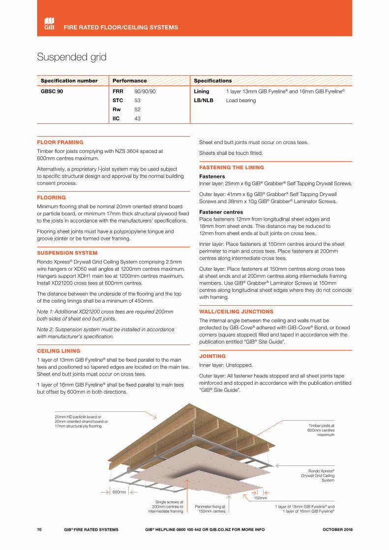
Suspended grid
Specification number Performance Specifications
GBSC 90 FRR
STC
Rw
IIC
90/90/90
53
52
43
Lining
LB/NLB
1 layer 13mm GIB Fyreline® and 16mm GIB Fyreline®
Load bearing
FLOOR FRAMING
Timber floor joists complying with NZS 3604 spaced at 600mm centres maximum.
Alternatively, a proprietary I-joist system may be used subject to specific structural design and approval by the normal building consent process.
FLOORING
Minimum flooring shall be nominal 20mm oriented strand board or particle board, or minimum 17mm thick structural plywood fixed to the joists in accordance with the manufacturers’ specifications.
Flooring sheet joints must have a polypropylene tongue and groove jointer or be formed over framing.
SUSPENSION SYSTEM
Rondo Xpress® Drywall Grid Ceiling System comprising 2.5mm wire hangers or XD50 wall angles at 1200mm centres maximum. Hangers support XDH1 main tee at 1200mm centres maximum. Install XD21200 cross tees at 600mm centres.
The distance between the underside of the flooring and the top of the ceiling linings shall be a minimum of 450mm.
Note 1: Additional XD21200 cross tees are required 200mm both sides of sheet end butt joints.
Note 2: Suspension system must be installed in accordance with manufacturer’s specification.
CEILING LINING
1 layer of 13mm GIB Fyreline® shall be fixed parallel to the main tees and positioned so tapered edges are located on the main tee. Sheet end butt joints must occur on cross tees.
1 layer of 16mm GIB Fyreline® shall be fixed parallel to main tees but offset by 600mm in both directions.
Sheet end butt joints must occur on cross tees.
Sheets shall be touch fitted.
FASTENING THE LINING
Fasteners Inner layer: 25mm x 6g GIB® Grabber® Self Tapping Drywall Screws.
Outer layer: 41mm x 6g GIB® Grabber® Self Tapping Drywall Screws and 38mm x 10g GIB® Grabber® Laminator Screws.
Fastener centres Place fasteners 12mm from longitudinal sheet edges and 18mm from sheet ends. This distance may be reduced to 12mm from sheet ends at butt joints on cross tees.
Inner layer: Place fasteners at 150mm centres around the sheet perimeter to main and cross tees. Place fasteners at 200mm centres along intermediate cross tees.
Outer layer: Place fasteners at 150mm centres along cross tees at sheet ends and at 200mm centres along intermediate framing members. Use GIB® Grabber® Laminator Screws at 150mm centres along longitudinal sheet edges where they do not coincide with framing.
WALL/CEILING JUNCTIONS
The internal angle between the ceiling and walls must be protected by GIB-Cove® adhered with GIB-Cove® Bond, or boxed corners (square stopped) filled and taped in accordance with the publication entitled “GIB® Site Guide”.
JOINTING
Inner layer: Unstopped.
Outer layer: All fastener heads stopped and all sheet joints tape reinforced and stopped in accordance with the publication entitled “GIB® Site Guide”.
20mm HD particle board or 20mm oriented strand board or 17mm structural ply flooring
1 layer of 13mm GIB Fyreline® and 1 layer of 16mm GIB Fyreline®
Timber joists at 600mm centres
maximum
Perimeter fixing at 150mm centres
Rondo Xpress® Drywall Grid Ceiling
System
600mm
150mmSingle screws at
200mm centres to intermediate framing
70 GIB® FIRE RATED SYSTEMS GIB® HELPLINE 0800 100 442 OR GIB.CO.NZ FOR MORE INFO OCTOBER 2018
FIRE RATED FLOOR/CEILING SYSTEMS
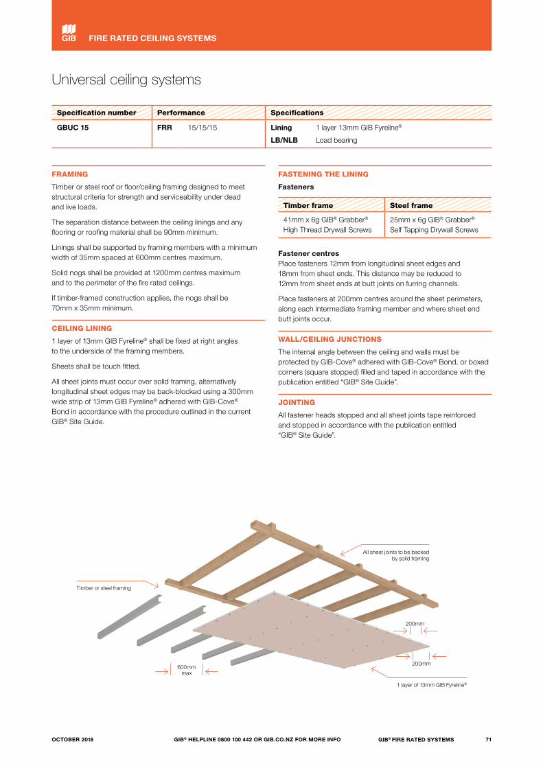
Universal ceiling systems
Specification number Performance Specifications
GBUC 15 FRR 15/15/15 Lining
LB/NLB
1 layer 13mm GIB Fyreline®
Load bearing
FRAMING
Timber or steel roof or floor/ceiling framing designed to meet structural criteria for strength and serviceability under dead and live loads.
The separation distance between the ceiling linings and any flooring or roofing material shall be 90mm minimum.
Linings shall be supported by framing members with a minimum width of 35mm spaced at 600mm centres maximum.
Solid nogs shall be provided at 1200mm centres maximum and to the perimeter of the fire rated ceilings.
If timber-framed construction applies, the nogs shall be 70mm x 35mm minimum.
CEILING LINING
1 layer of 13mm GIB Fyreline® shall be fixed at right angles to the underside of the framing members.
Sheets shall be touch fitted.
All sheet joints must occur over solid framing, alternatively longitudinal sheet edges may be back-blocked using a 300mm wide strip of 13mm GIB Fyreline® adhered with GIB-Cove® Bond in accordance with the procedure outlined in the current GIB® Site Guide.
FASTENING THE LINING
Fasteners
Timber frame Steel frame
41mm x 6g GIB® Grabber® High Thread Drywall Screws
25mm x 6g GIB® Grabber® Self Tapping Drywall Screws
Fastener centres Place fasteners 12mm from longitudinal sheet edges and 18mm from sheet ends. This distance may be reduced to 12mm from sheet ends at butt joints on furring channels.
Place fasteners at 200mm centres around the sheet perimeters, along each intermediate framing member and where sheet end butt joints occur.
WALL/CEILING JUNCTIONS
The internal angle between the ceiling and walls must be protected by GIB-Cove® adhered with GIB-Cove® Bond, or boxed corners (square stopped) filled and taped in accordance with the publication entitled “GIB® Site Guide”.
JOINTING
All fastener heads stopped and all sheet joints tape reinforced and stopped in accordance with the publication entitled “GIB® Site Guide”.
Timber or steel framing
All sheet joints to be backed by solid framing
600mm max
200mm
200mm
1 layer of 13mm GIB Fyreline®
71GIB® FIRE RATED SYSTEMSGIB® HELPLINE 0800 100 442 OR GIB.CO.NZ FOR MORE INFOOCTOBER 2018
FIRE RATED CEILING SYSTEMS
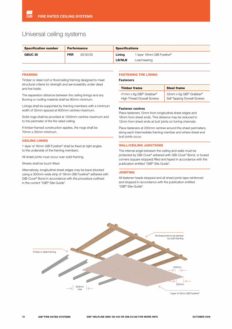
Timber or steel framing
Universal ceiling systems
Specification number Performance Specifications
GBUC 30 FRR 30/30/30 Lining
LB/NLB
1 layer 16mm GIB Fyreline®
Load bearing
FRAMING
Timber or steel roof or floor/ceiling framing designed to meet structural criteria for strength and serviceability under dead and live loads.
The separation distance between the ceiling linings and any flooring or roofing material shall be 90mm minimum.
Linings shall be supported by framing members with a minimum width of 35mm spaced at 600mm centres maximum.
Solid nogs shall be provided at 1200mm centres maximum and to the perimeter of the fire rated ceiling.
If timber-framed construction applies, the nogs shall be 70mm x 35mm minimum.
CEILING LINING
1 layer of 16mm GIB Fyreline® shall be fixed at right angles to the underside of the framing members.
All sheet joints must occur over solid framing.
Sheets shall be touch fitted.
Alternatively, longitudinal sheet edges may be back-blocked using a 300mm-wide strip of 16mm GIB Fyreline® adhered with GIB-Cove® Bond in accordance with the procedure outlined in the current “GIB® Site Guide”.
FASTENING THE LINING
Fasteners
Timber frame Steel frame
41mm x 6g GIB® Grabber® High Thread Drywall Screws
32mm x 6g GIB® Grabber® Self Tapping Drywall Screws
Fastener centres Place fasteners 12mm from longitudinal sheet edges and 18mm from sheet ends. This distance may be reduced to 12mm from sheet ends at butt joints on furring channels.
Place fasteners at 200mm centres around the sheet perimeters, along each intermediate framing member and where sheet end butt joints occur.
WALL/CEILING JUNCTIONS
The internal angle between the ceiling and walls must be protected by GIB-Cove® adhered with GIB-Cove® Bond, or boxed corners (square stopped) filled and taped in accordance with the publication entitled “GIB® Site Guide”.
JOINTING
All fastener heads stopped and all sheet joints tape reinforced and stopped in accordance with the publication entitled “GIB® Site Guide”.
600mm max
200mm
200mm
1 layer of 16mm GIB Fyreline®
All sheet joints to be backed by solid framing
72 GIB® FIRE RATED SYSTEMS GIB® HELPLINE 0800 100 442 OR GIB.CO.NZ FOR MORE INFO OCTOBER 2018
FIRE RATED CEILING SYSTEMS

Universal ceiling systems
Specification number Performance Specifications
GBUC 60 FRR 60/60/60 Lining
LB/NLB
2 layers 13mm GIB Fyreline®
Load bearing
FRAMING
Timber or steel roof or floor/ceiling framing designed to meet structural criteria for strength and serviceability under dead and live loads.
The separation distance between the ceiling linings and any flooring or roofing material shall be 90mm minimum.
Linings shall be supported by framing members with a minimum width of 35mm spaced at 600mm centres maximum.
In respect of the FRR for this particular system, nogs are required only at the perimeter of the fire rated ceiling.
If timber-framed construction applies, the nogs shall be 70mm x 35mm minimum.
CEILING LINING
2 layers of 13mm GIB Fyreline® shall be fixed at right angles to the underside of the framing members.
The joints of the second layer are offset 600mm from those in the first layer.
All sheet end butt joints must occur over solid framing.
Sheets shall be touch fitted.
FASTENING THE LINING
Fasteners
Layer Timber frame Steel frame
Inner layer 41mm x 6g GIB® Grabber® High Thread Drywall Screws
25mm x 6g GIB® Grabber® Self Tapping Drywall Screws
Outer layer 51mm x 7g GIB® Grabber® High Thread Drywall Screws
41mm x 6g GIB® Grabber® Self Tapping Drywall Screws
Fastener centres (both layers) Place fasteners 12mm from longitudinal sheet edges and 18mm from sheet ends. This distance may be reduced to 12mm from sheet ends at butt joints on furring channels.
Place fasteners at 200mm centres around the ceiling perimeter, along each intermediate framing member and where sheet end butt joints occur.
WALL/CEILING JUNCTIONS
The internal angle between the ceiling and walls must be protected by GIB-Cove® adhered with GIB-Cove® Bond, or boxed corners (square stopped) filled and taped in accordance with the publication entitled “GIB® Site Guide”.
JOINTING
Inner layer: Unstopped.
Outer layer: All fastener heads stopped and all sheet joints tape reinforced and stopped in accordance with the publication entitled “GIB® Site Guide”.
Timber or steel framing
2 layers of 13mm GIB Fyreline®
600mmmax
200mm
200mm All sheet ends to be backed by
solid framing
73GIB® FIRE RATED SYSTEMSGIB® HELPLINE 0800 100 442 OR GIB.CO.NZ FOR MORE INFOOCTOBER 2018
FIRE RATED CEILING SYSTEMS

Universal ceiling systems
Specification number Performance Specifications
GBUC 90 FRR 90/90/90 Lining
LB/NLB
2 layers 19mm GIB Fyreline®
Load bearing
GBUC 120* FRR 120/120/120 Lining
LB/NLB
2 layers 19mm GIB Fyreline®
Load bearing
FRAMING
Timber or steel roof or floor/ceiling framing designed to meet structural criteria for strength and serviceability under dead and live loads.
The separation distance between the ceiling linings and any flooring or roofing material shall be 90mm minimum.
Linings shall be supported by framing members with a minimum width of 35mm spaced at 600mm centres maximum.
Nogs are required only at the perimeter of the fire rated ceiling.
If timber-framed construction applies, the nogs shall be 70mm x 35mm minimum.
CEILING LINING
2 layers of 19mm GIB Fyreline® shall be fixed at right angles to the underside of the framing members.
The joints of the second layer are offset 600mm from those in the first layer.
All sheet end butt joints must occur over solid framing.
Sheets shall be touch fitted.
*Note: A 120-minute FRR (GBUC 120) is achieved with a minimum 200mm separation distance between the ceiling linings and any flooring or roofing material, or with the addition of Pink® Batts® BIB R1.8 (75mm) glass wool insulation installed between the framing.
FASTENING THE LINING
Fasteners
Layer Timber frame Steel frame
Inner layer 41mm x 6g GIB® Grabber® High Thread Drywall Screws
32mm x 6g GIB® Grabber® Self Tapping Drywall Screws
Outer layer 57mm x 7g GIB® Grabber® High Thread Drywall Screws
51mm x 7g GIB® Grabber® Self Tapping Drywall Screws
Fastener centres (both layers) Place fasteners 12mm from longitudinal sheet edges and 18mm from sheet ends. This distance may be reduced to 12mm from sheet ends at butt joints on furring channels.
Place fasteners at 200mm centres around the ceiling perimeter, along each intermediate framing member and where sheet end butt joints occur.
WALL/CEILING JUNCTIONS
The internal angle between the ceiling and walls must be protected by GIB-Cove® adhered with GIB-Cove® Bond, or boxed corners (square stopped) filled and taped in accordance with the publication entitled “GIB® Site Guide”.
JOINTING
Inner layer: Unstopped.
Outer layer: All fastener heads stopped and all sheet joints tape reinforced and stopped in accordance with the publication entitled “GIB® Site Guide”.
Timber or steel framing
2 layers of 19mm GIB Fyreline®
600mmmax
200mm
200mm All sheet ends to be backed by
solid framing
74 GIB® FIRE RATED SYSTEMS GIB® HELPLINE 0800 100 442 OR GIB.CO.NZ FOR MORE INFO OCTOBER 2018
FIRE RATED CEILING SYSTEMS

75GIB® FIRE RATED SYSTEMSGIB® HELPLINE 0800 100 442 OR GIB.CO.NZ FOR MORE INFOOCTOBER 2018
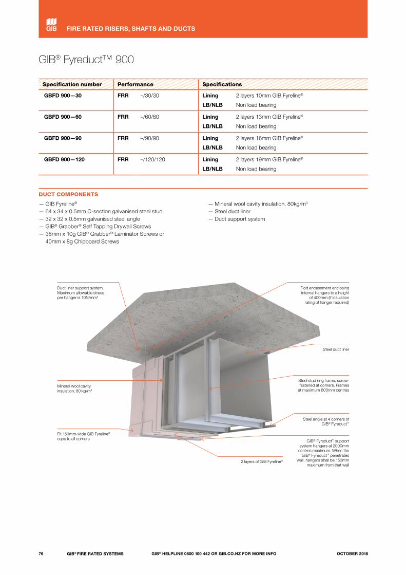
GIB® Fyreduct™ 900
Specification number Performance Specifications
GBFD 900—30 FRR –/30/30 Lining
LB/NLB
2 layers 10mm GIB Fyreline®
Non load bearing
GBFD 900—60 FRR –/60/60 Lining
LB/NLB
2 layers 13mm GIB Fyreline®
Non load bearing
GBFD 900—90 FRR –/90/90 Lining
LB/NLB
2 layers 16mm GIB Fyreline®
Non load bearing
GBFD 900—120 FRR –/120/120 Lining
LB/NLB
2 layers 19mm GIB Fyreline®
Non load bearing
DUCT COMPONENTS
— GIB Fyreline®
— 64 x 34 x 0.5mm C-section galvanised steel stud— 32 x 32 x 0.5mm galvanised steel angle— GIB® Grabber® Self Tapping Drywall Screws — 38mm x 10g GIB® Grabber® Laminator Screws or
40mm x 8g Chipboard Screws
— Mineral wool cavity insulation, 80kg/m3
— Steel duct liner— Duct support system
Duct liner support system.Maximum allowable stress per hanger is 10N/mm2
Rod encasement enclosing internal hangers to a height
of 400mm (if insulation rating of hanger required)
Steel duct liner
Steel stud ring frame, screw- fastened at corners. Frames
at maximum 600mm centres
Steel angle at 4 corners of GIB® Fyreduct™
GIB® Fyreduct™ support system hangers at 2000mm
centres maximum. When the GIB® Fyreduct™ penetrates
wall, hangers shall be 150mm maximum from that wall
2 layers of GIB Fyreline®
Mineral wool cavity insulation, 80 kg/m3
Fit 150mm-wide GIB Fyreline® caps to all corners
76 GIB® FIRE RATED SYSTEMS GIB® HELPLINE 0800 100 442 OR GIB.CO.NZ FOR MORE INFO OCTOBER 2018
FIRE RATED RISERS, SHAFTS AND DUCTS
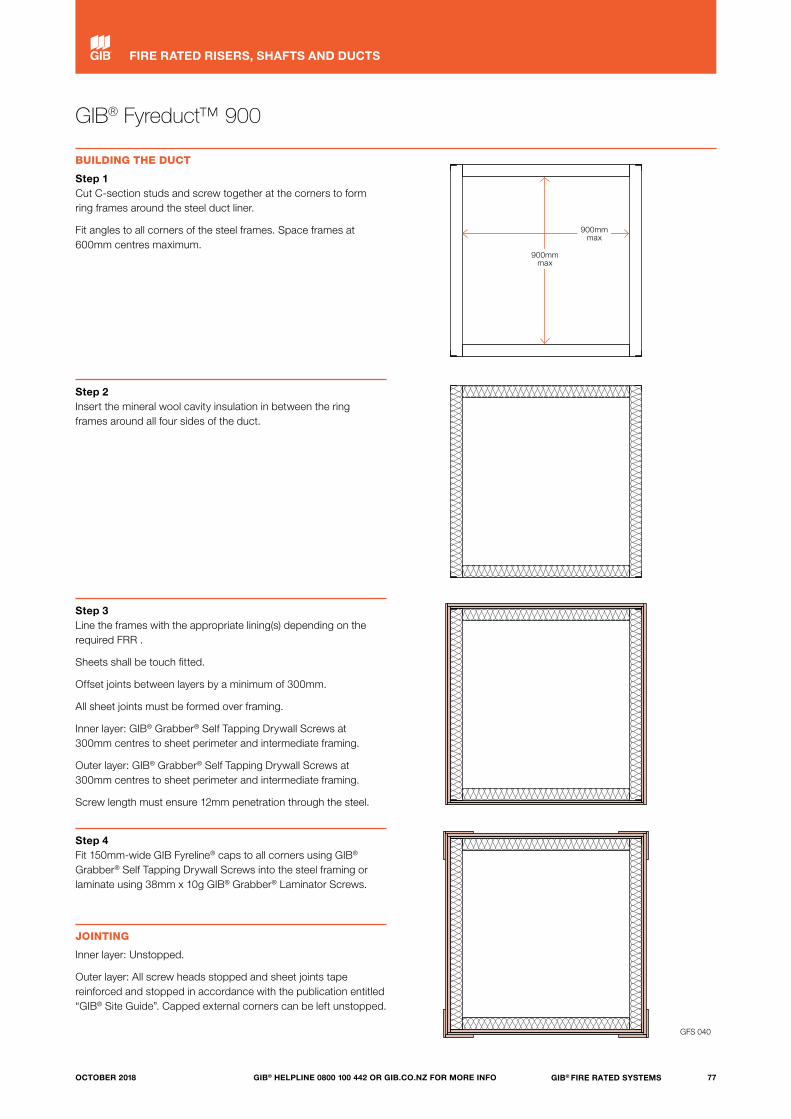
GIB® Fyreduct™ 900
BUILDING THE DUCT
Step 1Cut C-section studs and screw together at the corners to form ring frames around the steel duct liner.
Fit angles to all corners of the steel frames. Space frames at 600mm centres maximum.
Step 2Insert the mineral wool cavity insulation in between the ring frames around all four sides of the duct.
Step 3Line the frames with the appropriate lining(s) depending on the required FRR .
Sheets shall be touch fitted.
Offset joints between layers by a minimum of 300mm.
All sheet joints must be formed over framing.
Inner layer: GIB® Grabber® Self Tapping Drywall Screws at 300mm centres to sheet perimeter and intermediate framing.
Outer layer: GIB® Grabber® Self Tapping Drywall Screws at 300mm centres to sheet perimeter and intermediate framing.
Screw length must ensure 12mm penetration through the steel.
Step 4Fit 150mm-wide GIB Fyreline® caps to all corners using GIB® Grabber® Self Tapping Drywall Screws into the steel framing or laminate using 38mm x 10g GIB® Grabber® Laminator Screws.
JOINTING
Inner layer: Unstopped.
Outer layer: All screw heads stopped and sheet joints tape reinforced and stopped in accordance with the publication entitled “GIB® Site Guide”. Capped external corners can be left unstopped.
900mmmax
900mmmax
GFS 040
77GIB® FIRE RATED SYSTEMSGIB® HELPLINE 0800 100 442 OR GIB.CO.NZ FOR MORE INFOOCTOBER 2018
FIRE RATED RISERS, SHAFTS AND DUCTS
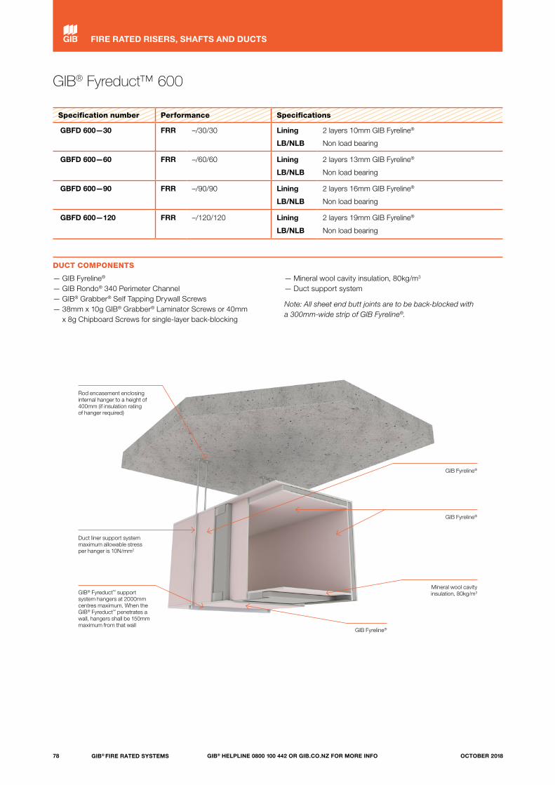
GIB® Fyreduct™ 600
Specification number Performance Specifications
GBFD 600—30 FRR –/30/30 Lining
LB/NLB
2 layers 10mm GIB Fyreline®
Non load bearing
GBFD 600—60 FRR –/60/60 Lining
LB/NLB
2 layers 13mm GIB Fyreline®
Non load bearing
GBFD 600—90 FRR –/90/90 Lining
LB/NLB
2 layers 16mm GIB Fyreline®
Non load bearing
GBFD 600—120 FRR –/120/120 Lining
LB/NLB
2 layers 19mm GIB Fyreline®
Non load bearing
DUCT COMPONENTS
— GIB Fyreline®
— GIB Rondo® 340 Perimeter Channel— GIB® Grabber® Self Tapping Drywall Screws— 38mm x 10g GIB® Grabber® Laminator Screws or 40mm
x 8g Chipboard Screws for single-layer back-blocking
— Mineral wool cavity insulation, 80kg/m3 — Duct support system
Note: All sheet end butt joints are to be back-blocked with a 300mm-wide strip of GIB Fyreline®.
Rod encasement enclosing internal hanger to a height of 400mm (if insulation rating of hanger required)
Duct liner support system maximum allowable stress per hanger is 10N/mm2
GIB® Fyreduct™ support system hangers at 2000mm centres maximum. When the GIB® Fyreduct™ penetrates a wall, hangers shall be 150mm maximum from that wall
GIB Fyreline®
GIB Fyreline®
GIB Fyreline®
Mineral wool cavity insulation, 80kg/m3
78 GIB® FIRE RATED SYSTEMS GIB® HELPLINE 0800 100 442 OR GIB.CO.NZ FOR MORE INFO OCTOBER 2018
FIRE RATED RISERS, SHAFTS AND DUCTS
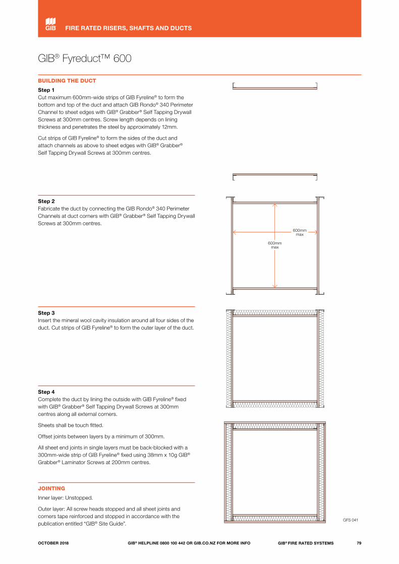
GIB® Fyreduct™ 600
BUILDING THE DUCT
Step 1Cut maximum 600mm-wide strips of GIB Fyreline® to form the bottom and top of the duct and attach GIB Rondo® 340 Perimeter Channel to sheet edges with GIB® Grabber® Self Tapping Drywall Screws at 300mm centres. Screw length depends on lining thickness and penetrates the steel by approximately 12mm.
Cut strips of GIB Fyreline® to form the sides of the duct and attach channels as above to sheet edges with GIB® Grabber® Self Tapping Drywall Screws at 300mm centres.
Step 2Fabricate the duct by connecting the GIB Rondo® 340 Perimeter Channels at duct corners with GIB® Grabber® Self Tapping Drywall Screws at 300mm centres.
Step 3Insert the mineral wool cavity insulation around all four sides of the duct. Cut strips of GIB Fyreline® to form the outer layer of the duct.
Step 4Complete the duct by lining the outside with GIB Fyreline® fixed with GIB® Grabber® Self Tapping Drywall Screws at 300mm centres along all external corners.
Sheets shall be touch fitted.
Offset joints between layers by a minimum of 300mm.
All sheet end joints in single layers must be back-blocked with a 300mm-wide strip of GIB Fyreline® fixed using 38mm x 10g GIB® Grabber® Laminator Screws at 200mm centres.
JOINTING
Inner layer: Unstopped.
Outer layer: All screw heads stopped and all sheet joints and corners tape reinforced and stopped in accordance with the publication entitled “GIB® Site Guide”.
600mmmax
600mmmax
GFS 041
79GIB® FIRE RATED SYSTEMSGIB® HELPLINE 0800 100 442 OR GIB.CO.NZ FOR MORE INFOOCTOBER 2018
FIRE RATED RISERS, SHAFTS AND DUCTS
GIB® Ventshaft
Specification number Performance Specifications
GVS 60 FRR –/60/60 Lining
LB/NLB
3 x 16mm GIB Fyreline®
Non load bearing
GIB® Ventshaft is constructed from the landing side of the shaft.
FRAMING
Primary horizontal angles25mm x 50mm (0.75BMT) metal angles fixed to floor slab and slab soffit on all sides. Ensure a good fit of the angle at the corners. Fix with steel masonry anchors at 400mm centres.
Mark the position of the anchors to ensure an offset with the secondary angle fixings.
Primary vertical angles25mm x 50mm (0.75BMT) metal angles to all corners full height in one continuous straight length ensuring good fit slab to slab. Fix with 16mm panhead self-tapping screws.
Secondary anglesAfter the first layer of 16mm GIB Fyreline® has been fixed, fix 25mm x 50mm (0.75BMT) metal angles to the base and head positions on all sides ensuring a good fit at all corners. Fix with metal anchors at 400mm centres. Stagger anchors 200mm from primary anchors.
WALL HEIGHT
The wall height is limited to 3000mm.
LINING AND FASTENING
First layerFix the first layer of 16mm GIB Fyreline® to the top and bottom metal angles at 600mm centres horizontally commencing from one end or corner progressively attaching around the shaft using 32mm x 6g GIB® Grabber® Self Tapping Drywall Screws. Fix the 16mm GIB Fyreline® to the metal angles at the corners and walls at 400mm centres commencing 200mm up from the base angle using 32mm x 6g GIB® Grabber® Self Tapping Drywall Screws. Fix plasterboard hard to floor slab and slab soffit.
Second layer laminationCut sheets to provide a good fit slab to slab and at intersecting walls. Mark the face of the sheet 12mm from the tapered edges, 18mm from sheet ends, and with vertical lines at 400mm centres.
Mark fasteners at 400mm centres along these lines, starting at 18mm and then 200mm from the bottom.
Stagger/overlap sheets by no less than 300mm. Fix second layer of 16mm GIB Fyreline® to metal angles around the perimeter using 41mm x 6g GIB® Grabber® Self Tapping Drywall Screws.
Laminate the second layer to the first sheet using 38mm x 10g GIB® Grabber® Laminator Screws or 40mm x 8g Chipboard Screws. The tapered joint in the previous layer must be supported by an additional double line of GIB® Grabber® Laminator Screws.
Third layer laminationCut sheets to provide a good fit slab to slab and at intersecting walls. Mark the face of the sheet 12mm from the tapered edges, 18mm from sheet ends, and with vertical lines at 400mm centres. Mark fasteners at 400mm centres along these lines, starting at 18mm and then 400mm from the bottom.
Apply GIB Fire Soundseal® to the perimeter of the second layer before installing the third layer.
Stagger/overlap sheets by no less than 300mm. Screw fix at the perimeter to the metal angles using 63mm x 8g GIB® Grabber® Self Tapping Drywall screws.
Laminate the third layer to the second sheet using 38mm x 10g GIB® Grabber® Laminator Screws or 40mm x 8g Chipboard Screws.
Ensure boards overlap at corners.
JOINTING
Inner layers: Unstopped.
Outer layer: All screw heads stopped and all sheet joints and corners tape reinforced and stopped in accordance with the publication entitled “GIB® Site Guide”.
80 GIB® FIRE RATED SYSTEMS GIB® HELPLINE 0800 100 442 OR GIB.CO.NZ FOR MORE INFO OCTOBER 2018
FIRE RATED RISERS, SHAFTS AND DUCTS
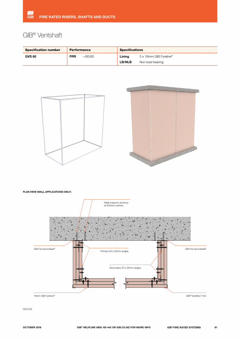
GIB® Ventshaft
Specification number Performance Specifications
GVS 60 FRR –/60/60 Lining
LB/NLB
3 x 16mm GIB Fyreline®
Non load bearing
GIB Fire Soundseal®
PLAN VIEW (WALL APPLICATIONS ONLY)
Steel masonry anchors at 400mm centres
Primary 50 x 25mm angles
Secondary 50 x 25mm angles
GIB Fire Soundseal®
16mm GIB Fyreline® GIB® Goldline™ trim
GFS 042
81GIB® FIRE RATED SYSTEMSGIB® HELPLINE 0800 100 442 OR GIB.CO.NZ FOR MORE INFOOCTOBER 2018
FIRE RATED RISERS, SHAFTS AND DUCTS
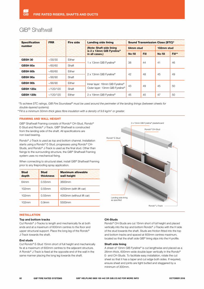
GIB® Shaftwall
Specification number
FRR Fire side Landing side lining Sound Transmission Class (STC)*
(Note: Shaft side lining is 2 x 13mm GIB Fyreline® in all cases.)
64mm stud 102mm stud
No fill Fill No fill Fill**
GBSH 30 –/30/30 Either1 x 13mm GIB Fyreline® 38 44 41 46
GBSH 60a –/60/60 Shaft
GBSH 60b –/60/60 Either2 x 13mm GIB Fyreline® 42 48 45 49
GBSH 90a –/90/90 Shaft
GBSH 90b –/90/90 Either Inner layer: 16mm GIB Fyreline® Outer layer: 13mm GIB Fyreline®
43 49 45 50GBSH 120a –/120/120 Shaft
GBSH 120b –/120/120 Either 2 x 19mm GIB Fyreline® 45 45 47 50
*To achieve STC ratings, GIB Fire Soundseal® must be used around the perimeter of the landing linings (between sheets for double-layered systems). **Fill is a minimum 50mm-thick glass fibre insulation with a density of 9.6 kg/m3 or greater.
FRAMING AND WALL HEIGHT
GIB® Shaftwall Framing consists of Rondo® CH-Stud, Rondo® E-Stud and Rondo® J-Track. GIB® Shaftwall is constructed from the landing side of the shaft. All specifications are non load bearing.
Rondo® J-Track is used as top and bottom channel. Installation starts using a Rondo® E-Stud, progresses using Rondo® CH-Studs, and Rondo® J-Track is used as the final stud. Other than fixings to the surrounding structure, the GIB® Shaftwall Framing system uses no mechanical fixing.
When connecting to structural steel, install GIB® Shaftwall Framing prior to any fireproofing spray application.
Stud depth
Stud thickness
Maximum allowable wall height
64mm 0.55mm 3600mm
102mm 0.55mm 4250mm (with lift car)
102mm 0.55mm 4350mm (without lift car)
102mm 0.9mm 5500mm
Rondo® E-Stud
Landing side lining as specified
2 x 13mm GIB Fyreline® plasterboard
Rondo® CH-Stud
Rondo® J-Track
INSTALLATION
Top and bottom tracksCut Rondo® J-Tracks to length and mechanically fix at both ends and at a maximum of 600mm centres to the floor and upper structural support. Place the long leg of the Rondo® J-Track towards the shaft.
End studsCut Rondo® E-Stud 15mm short of full height and mechanically fix at a maximum of 600mm centres to the adjacent structure. A Rondo® J-Track is fixed at the opposite end of the wall in the same manner placing the long leg towards the shaft.
CH-StudsRondo® CH-Studs are cut 15mm short of full height and placed vertically into the top and bottom Rondo® J-Tracks with the H side of the stud towards the shaft. Studs are friction fitted into the top and bottom tracks and spaced at 600mm centres maximum, located so that the shaft side GIB® lining slips into the H profile.
Shaft side liningA sheet of 13mm GIB Fyreline® is cut lengthwise and placed as a 26mm-thick, 600mm-wide double layer vertically in the Rondo® E- and CH-Studs. To facilitate easy installation, rotate the cut sheet so that it has a taper and cut edge both sides. If required, ensure sheet end joints are tight butted and staggered by a minimum of 300mm.
82 GIB® FIRE RATED SYSTEMS GIB® HELPLINE 0800 100 442 OR GIB.CO.NZ FOR MORE INFO OCTOBER 2018
FIRE RATED RISERS, SHAFTS AND DUCTS
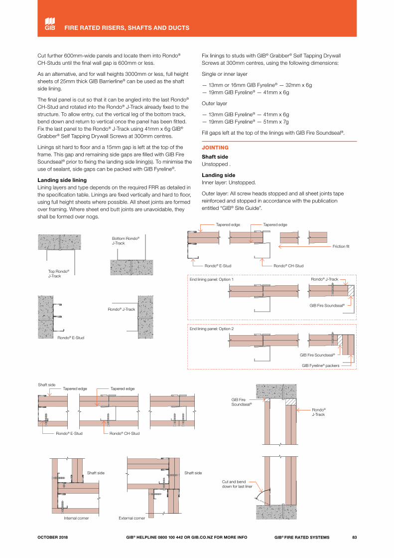
Top Rondo® J-Track
Rondo® E-Stud
Bottom Rondo® J-Track
Tapered edge
End lining panel: Option 1
Shaft side
Shaft side
Internal corner External corner
Shaft side
GIB Fire Soundseal®
Rondo® J-Track
Cut and bend down for last liner
End lining panel: Option 2
Tapered edge
Tapered edge
Rondo® E-Stud Rondo® CH-Stud
Tapered edge
Friction fit
Rondo® E-Stud Rondo® CH-Stud
Rondo® J-Track
GIB Fire Soundseal®
GIB Fire Soundseal®
GIB Fyreline® packers
Rondo® J-Track
Cut further 600mm-wide panels and locate them into Rondo® CH-Studs until the final wall gap is 600mm or less.
As an alternative, and for wall heights 3000mm or less, full height sheets of 25mm thick GIB Barrierline® can be used as the shaft side lining.
The final panel is cut so that it can be angled into the last Rondo® CH-Stud and rotated into the Rondo® J-Track already fixed to the structure. To allow entry, cut the vertical leg of the bottom track, bend down and return to vertical once the panel has been fitted. Fix the last panel to the Rondo® J-Track using 41mm x 6g GIB® Grabber® Self Tapping Drywall Screws at 300mm centres.
Linings sit hard to floor and a 15mm gap is left at the top of the frame. This gap and remaining side gaps are filled with GIB Fire Soundseal® prior to fixing the landing side lining(s). To minimise the use of sealant, side gaps can be packed with GIB Fyreline®.
Landing side liningLining layers and type depends on the required FRR as detailed in the specification table. Linings are fixed vertically and hard to floor, using full height sheets where possible. All sheet joints are formed over framing. Where sheet end butt joints are unavoidable, they shall be formed over nogs.
Fix linings to studs with GIB® Grabber® Self Tapping Drywall Screws at 300mm centres, using the following dimensions:
Single or inner layer
— 13mm or 16mm GIB Fyreline® — 32mm x 6g— 19mm GIB Fyreline® — 41mm x 6g
Outer layer
— 13mm GIB Fyreline® — 41mm x 6g— 19mm GIB Fyreline® — 51mm x 7g
Fill gaps left at the top of the linings with GIB Fire Soundseal®.
JOINTING
Shaft sideUnstopped .
Landing sideInner layer: Unstopped.
Outer layer: All screw heads stopped and all sheet joints tape reinforced and stopped in accordance with the publication entitled “GIB® Site Guide”.
83GIB® FIRE RATED SYSTEMSGIB® HELPLINE 0800 100 442 OR GIB.CO.NZ FOR MORE INFOOCTOBER 2018
FIRE RATED RISERS, SHAFTS AND DUCTS
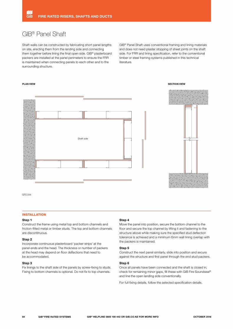
GIB® Panel Shaft
Shaft walls can be constructed by fabricating short panel lengths on site, erecting them from the landing side and connecting them together before lining the final open side. GIB® plasterboard packers are installed at the panel perimeters to ensure the FRR is maintained when connecting panels to each other and to the surrounding structure.
GIB® Panel Shaft uses conventional framing and lining materials and does not need plaster stopping of sheet joints on the shaft side. For FRR and lining specification, refer to the conventional timber or steel framing systems published in this technical literature.
INSTALLATION
Step 1Construct the frame using metal top and bottom channels and friction-fitted metal or timber studs. The top and bottom channels are discontinuous.
Step 2Incorporate continuous plasterboard ‘packer strips’ at the panel ends and the head. The thickness or number of packers at the head may depend on floor deflections that need to be accommodated.
Step 3Fix linings to the shaft side of the panels by screw-fixing to studs. Fixing to bottom channels is optional. Do not fix to top channels.
Step 4Move the panel into position, secure the bottom channel to the floor and secure the top channel by lifting it and fastening to the structure above while making sure the specified stud deflection tolerance is achieved and a minimum 6mm wall lining overlap with the packers is maintained.
Step 5Construct the next panel similarly, slide into position and secure against the structure and first panel through the end stud packers.
Step 6Once all panels have been connected and the shaft is closed in, check for remaining minor gaps, fill these with GIB Fire Soundseal® and line the open landing side conventionally.
For full fixing details, follow the selected specification details.
Shaft side
GIB®
© Winstone Wallboards Limited 2014. TERMS OF USE: The USER of these CAD drawings and related information is authorised to reproduce and distribute exact copies or exact extracts of these CAD drawings for the sole purpose of detailing, specifying, using, and promoting the use of Winstone Wallboards Ltd products and systems. It is the USER's responsibility to ensure full building performance specifications and to ensure specification and installation of GIB® products and systems are in accordance with Winstone Wallboards Ltd GIB® publications. Appropriate expert advice should always be obtained to ensure suitability of these drawings for your specific application. See www.gib.co.nz for full terms of use. The USER is deemed to accept the terms of use.
© copyright 2011 Winstone Wallboards Ltd All Dimensions are to be site checked before construction and installation
File:Scale:
Date:
Reference 1 : 5Panelshaft Layout
GFS-P066B14 May 18
GFS-P066B
Shaft side
GFS 044
PLAN VIEW SECTION VIEW
84 GIB® FIRE RATED SYSTEMS GIB® HELPLINE 0800 100 442 OR GIB.CO.NZ FOR MORE INFO OCTOBER 2018
FIRE RATED RISERS, SHAFTS AND DUCTS

Chase walls
Services may be reticulated within the cavity space between double-stud chase walls. Fire protection of fire compartments either side of the chase wall will be achieved when using timber- or steel-framed non-loadbearing vertical fire separations.
The following conditions apply:
— The FRR applies from outside to outside of the chase wall system and not from inside to outside.
— Service penetrations must be made in the chase wall as described in this publication or in accordance with the requirements for proprietary tested penetration seals.
— Non-loadbearing wall constructions only may be used.— Approved variations are:
i) Chase wall systems may be stiffened using cross-bracing between opposite framing members comprising either stud sections fastened at intervals to opposing studs or rectangular pieces of GIB® fastened by perimeter fixings to opposing studs. ii) Stud spacing between walls in the double-stud construction is optional.
Example of conventional single-stud wall construction for two way FRR. Framing may be timber or steel
Example of chase wall construction
Height up to 4000mm for conventional wall systems. Height may exceed 4000mm for certain approved construction
Linings to outside
Stud spacing optional
HeightHeight
Ser
vice
s re
ticul
atio
n in
cav
ity
GFS 045
SECTION VIEW
85GIB® FIRE RATED SYSTEMSGIB® HELPLINE 0800 100 442 OR GIB.CO.NZ FOR MORE INFOOCTOBER 2018
FIRE RATED RISERS, SHAFTS AND DUCTS

Fire rated protection of columns and beams — timber strapping
SCOPE OF USE
The options offered in this section provide quick reference solutions for the fire protection of structural steel, timber and concrete columns and beams. The illustrations below show steel members.
For engineered solutions, tailored to meet specific column and beam types, sizes and loading conditions, specific fire engineering design is required.
Specification number
FRR (structural adequacy rating*)
Lining requirement steel, timber, concrete columns and beams
GBCBT 15 15/-/- 1 x 13mm GIB® Standard
GBCBT 30a 30/-/- 1 x 16mm GIB Fyreline®
GBCBT 30b 30/-/- 2 x 10mm GIB Fyreline®
GBCBT 60 60/-/- 2 x 13mm GIB Fyreline®
GBCBT 90 90/-/- 2 x 16mm GIB Fyreline®
GBCBT 120 120/-/- 2 x 19mm GIB Fyreline®
GBCBT 180 180/-/- 3 x 19mm GIB Fyreline®
*The FRR comprises values for structural adequacy/integrity/insulation. For loadbearing structural steel members (primary elements), the structural adequacy rating is usually the only requirement and prevents failure under vertical gravity loads during a fire.
STRAPPING
Strap column or beams with a timber cradle frame with a minimum nominal thickness of 35mm ensuring that the linings are supported by framing members spaced at 600mm centres maximum.
No air gap is required as long as support is provided to the protective linings at no more than 600mm centres each side of the structural member.
The protective linings can be direct fixed to timber columns and beams.
LINING
Install the linings in accordance with the required FRR as specified above. First and second layer joints must be formed over framing. In double-layer systems, the joints between the first and second layer must be offset by 300mm minimum.
FASTENING THE LINING
FastenersGIB® Grabber® High Thread Drywall Screws.
The fastener length must ensure a 20mm minimum penetration into timber.
Fastener centresSingle or outer layers must be fixed at 300mm centres maximum to framing spaced at 600mm centres maximum. Inner layers can be fixed at 600mm centres maximum to framing spaced at 600mm centres maximum.
JOINTING
Inner layer: Unstopped.
Outer layer: All fastener heads stopped and all sheet joints tape reinforced and stopped in accordance with the publication entitled “GIB® Site Guide”.
GIB Fire Soundseal®
Solid nogs between joists
86 GIB® FIRE RATED SYSTEMS GIB® HELPLINE 0800 100 442 OR GIB.CO.NZ FOR MORE INFO OCTOBER 2018
FIRE RATED SYSTEMS
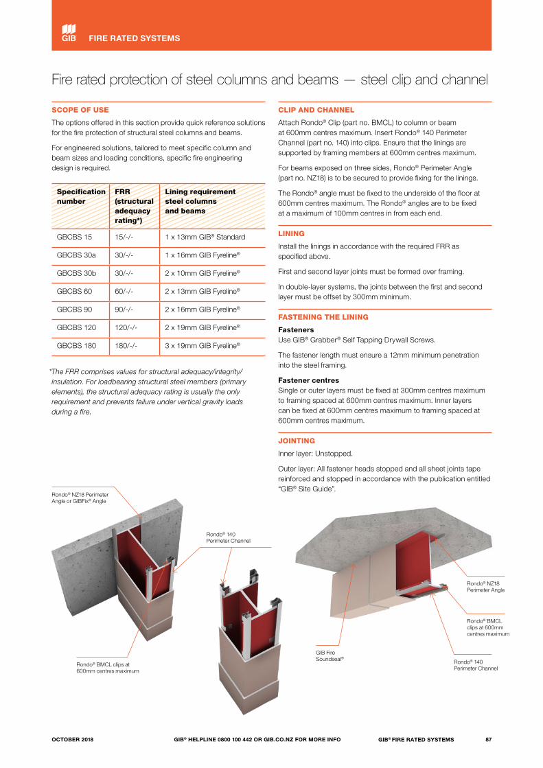
Fire rated protection of steel columns and beams — steel clip and channel
SCOPE OF USE
The options offered in this section provide quick reference solutions for the fire protection of structural steel columns and beams.
For engineered solutions, tailored to meet specific column and beam sizes and loading conditions, specific fire engineering design is required.
Specification number
FRR (structural adequacy rating*)
Lining requirement steel columns and beams
GBCBS 15 15/-/- 1 x 13mm GIB® Standard
GBCBS 30a 30/-/- 1 x 16mm GIB Fyreline®
GBCBS 30b 30/-/- 2 x 10mm GIB Fyreline®
GBCBS 60 60/-/- 2 x 13mm GIB Fyreline®
GBCBS 90 90/-/- 2 x 16mm GIB Fyreline®
GBCBS 120 120/-/- 2 x 19mm GIB Fyreline®
GBCBS 180 180/-/- 3 x 19mm GIB Fyreline®
*The FRR comprises values for structural adequacy/integrity/insulation. For loadbearing structural steel members (primary elements), the structural adequacy rating is usually the only requirement and prevents failure under vertical gravity loads during a fire.
CLIP AND CHANNEL
Attach Rondo® Clip (part no. BMCL) to column or beam at 600mm centres maximum. Insert Rondo® 140 Perimeter Channel (part no. 140) into clips. Ensure that the linings are supported by framing members at 600mm centres maximum.
For beams exposed on three sides, Rondo® Perimeter Angle (part no. NZ18) is to be secured to provide fixing for the linings.
The Rondo® angle must be fixed to the underside of the floor at 600mm centres maximum. The Rondo® angles are to be fixed at a maximum of 100mm centres in from each end.
LINING
Install the linings in accordance with the required FRR as specified above.
First and second layer joints must be formed over framing.
In double-layer systems, the joints between the first and second layer must be offset by 300mm minimum.
FASTENING THE LINING
FastenersUse GIB® Grabber® Self Tapping Drywall Screws.
The fastener length must ensure a 12mm minimum penetration into the steel framing.
Fastener centresSingle or outer layers must be fixed at 300mm centres maximum to framing spaced at 600mm centres maximum. Inner layers can be fixed at 600mm centres maximum to framing spaced at 600mm centres maximum.
JOINTING
Inner layer: Unstopped.
Outer layer: All fastener heads stopped and all sheet joints tape reinforced and stopped in accordance with the publication entitled “GIB® Site Guide”.
Rondo® NZ18 Perimeter Angle or GIBFix® Angle
Rondo® BMCL clips at 600mm centres maximum
GIB Fire Soundseal®
Rondo® NZ18 Perimeter Angle
Rondo® 140 Perimeter Channel
Rondo® BMCL clips at 600mm centres maximum
Rondo® 140 Perimeter Channel
87GIB® FIRE RATED SYSTEMSGIB® HELPLINE 0800 100 442 OR GIB.CO.NZ FOR MORE INFOOCTOBER 2018
FIRE RATED SYSTEMS
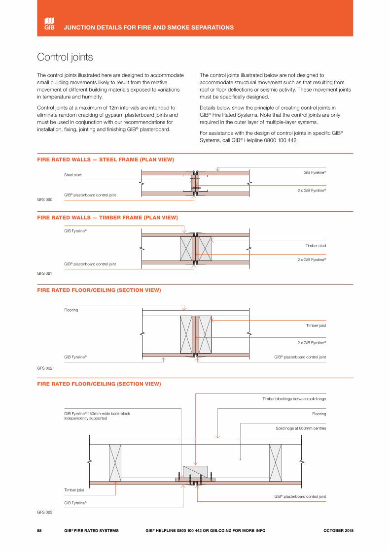
Control joints
The control joints illustrated here are designed to accommodate small building movements likely to result from the relative movement of different building materials exposed to variations in temperature and humidity.
Control joints at a maximum of 12m intervals are intended to eliminate random cracking of gypsum plasterboard joints and must be used in conjunction with our recommendations for installation, fixing, jointing and finishing GIB® plasterboard.
The control joints illustrated below are not designed to accommodate structural movement such as that resulting from roof or floor deflections or seismic activity. These movement joints must be specifically designed.
Details below show the principle of creating control joints in GIB® Fire Rated Systems. Note that the control joints are only required in the outer layer of multiple-layer systems.
For assistance with the design of control joints in specific GIB® Systems, call GIB® Helpline 0800 100 442.
FIRE RATED WALLS — STEEL FRAME (PLAN VIEW)
FIRE RATED WALLS — TIMBER FRAME (PLAN VIEW)
FIRE RATED FLOOR/CEILING (SECTION VIEW)
FIRE RATED FLOOR/CEILING (SECTION VIEW)
GFS 061
GFS 062
GFS 063
GFS 060
Steel stud
GIB Fyreline®
Flooring
GIB Fyreline® 150mm-wide back-block independently supported
GIB Fyreline®
Solid nogs at 600mm centres
Flooring
Timber blockings between solid nogs
Timber stud
Timber joist
GIB® plasterboard control joint
GIB® plasterboard control joint
GIB Fyreline®
GIB Fyreline®
Timber joist
GIB® plasterboard control joint
GIB® plasterboard control joint
2 x GIB Fyreline®
2 x GIB Fyreline®
2 x GIB Fyreline®
88 GIB® FIRE RATED SYSTEMS GIB® HELPLINE 0800 100 442 OR GIB.CO.NZ FOR MORE INFO OCTOBER 2018
JUNCTION DETAILS FOR FIRE AND SMOKE SEPARATIONS
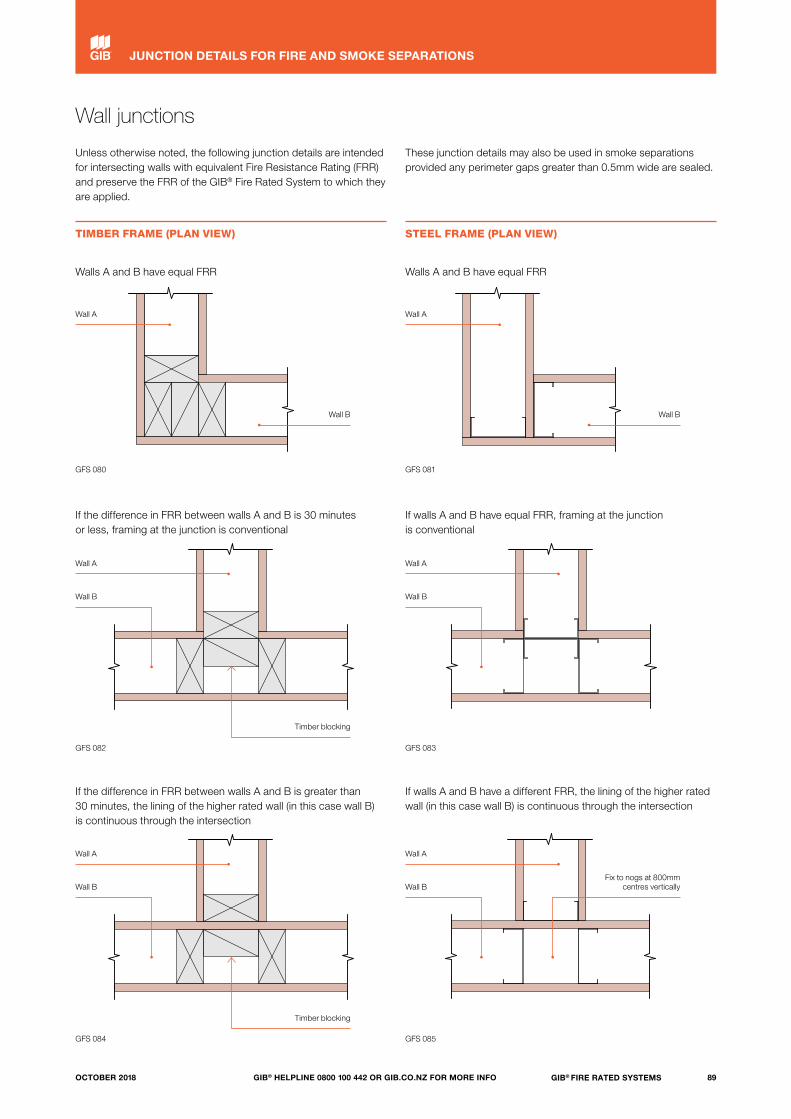
Wall junctions
Unless otherwise noted, the following junction details are intended for intersecting walls with equivalent Fire Resistance Rating (FRR) and preserve the FRR of the GIB® Fire Rated System to which they are applied.
These junction details may also be used in smoke separations provided any perimeter gaps greater than 0.5mm wide are sealed.
TIMBER FRAME (PLAN VIEW) STEEL FRAME (PLAN VIEW)
GFS 084
GFS 082
GFS 080
GFS 085
GFS 083
GFS 081
Walls A and B have equal FRR
If the difference in FRR between walls A and B is 30 minutes or less, framing at the junction is conventional
If walls A and B have equal FRR, framing at the junction is conventional
If the difference in FRR between walls A and B is greater than 30 minutes, the lining of the higher rated wall (in this case wall B) is continuous through the intersection
If walls A and B have a different FRR, the lining of the higher rated wall (in this case wall B) is continuous through the intersection
Walls A and B have equal FRR
Wall A
Wall A Wall A
Wall AWall A
Wall B Wall B
Wall BWall BFix to nogs at 800mm
centres vertically
Wall A
Wall B
Timber blocking
Timber blocking
Wall B
89GIB® FIRE RATED SYSTEMSGIB® HELPLINE 0800 100 442 OR GIB.CO.NZ FOR MORE INFOOCTOBER 2018
JUNCTION DETAILS FOR FIRE AND SMOKE SEPARATIONS
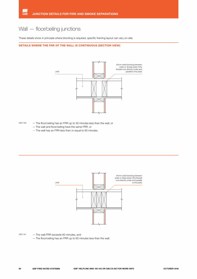
Wall — floor/ceiling junctions
These details show in principle where blocking is required, specific framing layout can vary on-site.
DETAILS WHERE THE FRR OF THE WALL IS CONTINUOUS (SECTION VIEW)
— The floor/ceiling has an FRR up to 30 minutes less than the wall, or— The wall and floor/ceiling have the same FRR, or— The wall has an FRR less than or equal to 60 minutes.
GFS 100
— The wall FRR exceeds 60 minutes, and — The floor/ceiling has an FRR up to 60 minutes less than the wall.
GFS 101
45mm solid blocking between joists or double joists if the
firewall runs directly under and parallel to the joists
45mm solid blocking between joists or triple joists if the firewall runs directly under and parallel
to the joists
Joist
Joist
90 GIB® FIRE RATED SYSTEMS GIB® HELPLINE 0800 100 442 OR GIB.CO.NZ FOR MORE INFO OCTOBER 2018
JUNCTION DETAILS FOR FIRE AND SMOKE SEPARATIONS
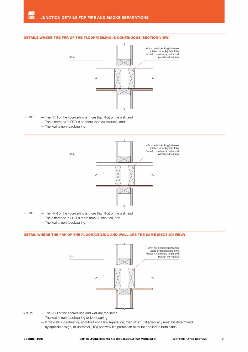
— The FRR of the floor/ceiling and wall are the same— The wall is non-loadbearing or loadbearing— If the wall is loadbearing and itself not a fire separation, then structural adequacy must be determined
by specific design, or universal (UW) one way fire protection must be applied to both sides.
— The FRR of the floor/ceiling is more than that of the wall, and— The difference in FRR is no more than 30 minutes, and— The wall is non-loadbearing.
DETAILS WHERE THE FRR OF THE FLOOR/CEILING IS CONTINUOUS (SECTION VIEW)
DETAIL WHERE THE FRR OF THE FLOOR/CEILING AND WALL ARE THE SAME (SECTION VIEW)
GFS 102
GFS 104
— The FRR of the floor/ceiling is more than that of the wall, and— The difference in FRR is more than 30 minutes, and— The wall is non-loadbearing.
GFS 103
45mm solid blocking between joists or double joists if the
firewall runs directly under and parallel to the joists
45mm solid blocking between joists or double joists if the
firewall runs directly under and parallel to the joists
45mm solid blocking between joists or double joists if the
firewall runs directly under and parallel to the joists
Joist
Joist
Joist
91GIB® FIRE RATED SYSTEMSGIB® HELPLINE 0800 100 442 OR GIB.CO.NZ FOR MORE INFOOCTOBER 2018
JUNCTION DETAILS FOR FIRE AND SMOKE SEPARATIONS

Suspended ceiling to wall junctions
The junctions below join vertical fire separations to fire rated suspended ceiling systems, such as suspended grid and the GIB Clip® systems shown below.
Firewalls may extend from floor to floor or to the ceiling junction as shown. Wall-ceiling junctions without cavity barriers in the concealed space are alternative solutions requiring specific fire engineering justification.
GFS 120 GFS 121
GFS 122
GIB Clip®
GIB Clip®
Perimeter channel or GIBFix® Angle
Suspension system
C channel
600mm
Furring channel
Lining
Perimeter channel
92 GIB® FIRE RATED SYSTEMS GIB® HELPLINE 0800 100 442 OR GIB.CO.NZ FOR MORE INFO OCTOBER 2018
JUNCTION DETAILS FOR FIRE AND SMOKE SEPARATIONS
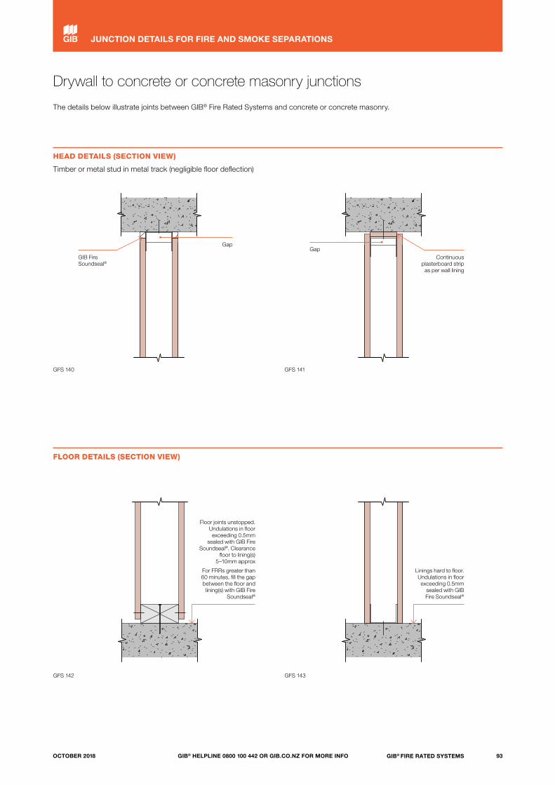
Drywall to concrete or concrete masonry junctions
The details below illustrate joints between GIB® Fire Rated Systems and concrete or concrete masonry.
HEAD DETAILS (SECTION VIEW)
Timber or metal stud in metal track (negligible floor deflection)
FLOOR DETAILS (SECTION VIEW)
GFS 140 GFS 141
GFS 142 GFS 143
GIB Fire Soundseal®
Continuous plasterboard strip
as per wall lining
GapGap
Floor joints unstopped. Undulations in floor exceeding 0.5mm
sealed with GIB Fire Soundseal®. Clearance
floor to lining(s) 5–10mm approx
For FRRs greater than 60 minutes, fill the gap between the floor and lining(s) with GIB Fire
Soundseal®
Linings hard to floor. Undulations in floor exceeding 0.5mm
sealed with GIB Fire Soundseal®
93GIB® FIRE RATED SYSTEMSGIB® HELPLINE 0800 100 442 OR GIB.CO.NZ FOR MORE INFOOCTOBER 2018
JUNCTION DETAILS FOR FIRE AND SMOKE SEPARATIONS
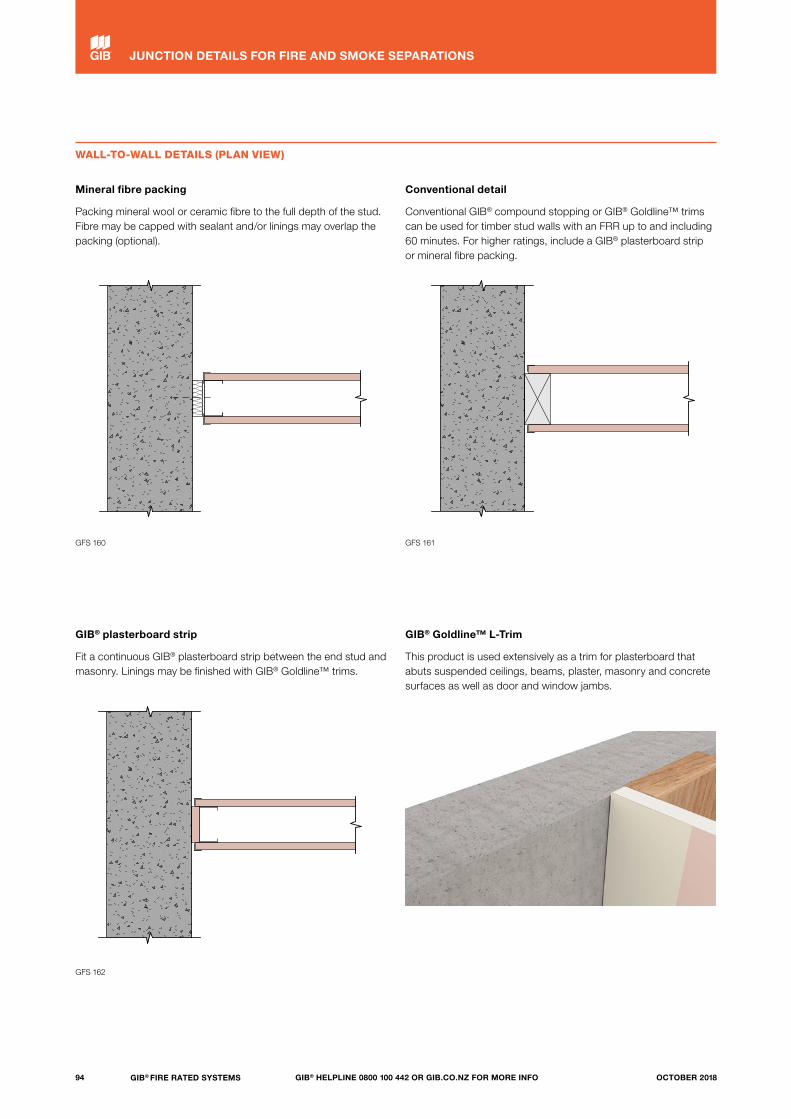
© Winstone Wallboards Limited 2016. TERMS OF USE: The USER of these CAD drawings and related information is authorised to reproduce and distribute exact copies or exact extracts of these CAD drawings for the sole purpose of detailing, specifying, using, and promoting the use of Winstone Wallboards Ltd products and systems. It is the USER's responsibility to ensure full building performance specifications and to ensure specification and installation of GIB® products and
systems are in accordance with Winstone Wallboards Ltd GIB® publications. Appropriate expert advice should always be obtained to ensure suitability of these drawings for your specific application. See www.gib.co.nz for full terms of use. The USER is deemed to accept the terms of use.
© Copyright 2016 Winstone Wallboards Ltd All Dimensions are to be site checked before construction and installation
Issue:
Scale:
Date:
Reference
File:
1 : 5
GFS-P073BDrywall To Masonry Junction - ContinuousPlasterboard Lining GFS-P073B10 AUG 18
-GFS-P073B Drywall To Masonry Junction - Continuous Plasterboard Lining
© Winstone Wallboards Limited 2016. TERMS OF USE: The USER of these CAD drawings and related information is authorised to reproduce and distribute exact copies or exact extracts of these CAD drawings for the sole purpose of detailing, specifying, using, and promoting the use of Winstone Wallboards Ltd products and systems. It is the USER's responsibility to ensure full building performance specifications and to ensure specification and installation of GIB® products and
systems are in accordance with Winstone Wallboards Ltd GIB® publications. Appropriate expert advice should always be obtained to ensure suitability of these drawings for your specific application. See www.gib.co.nz for full terms of use. The USER is deemed to accept the terms of use.
© Copyright 2016 Winstone Wallboards Ltd All Dimensions are to be site checked before construction and installation
Issue:
Scale:
Date:
Reference
File:
1 : 5
GFS-P073ADrywall To Masonry Junction - ConventionalCompound Stopping GFS-P073A10 AUG 18
-GFS-P073A Drywall To Masonry Junction - Conventional Compound Stopping
WALL-TO-WALL DETAILS (PLAN VIEW)
Mineral fibre packing
Packing mineral wool or ceramic fibre to the full depth of the stud. Fibre may be capped with sealant and/or linings may overlap the packing (optional).
GIB® plasterboard strip
Fit a continuous GIB® plasterboard strip between the end stud and masonry. Linings may be finished with GIB® Goldline™ trims.
Conventional detail
Conventional GIB® compound stopping or GIB® Goldline™ trims can be used for timber stud walls with an FRR up to and including 60 minutes. For higher ratings, include a GIB® plasterboard strip or mineral fibre packing.
GIB® Goldline™ L-Trim
This product is used extensively as a trim for plasterboard that abuts suspended ceilings, beams, plaster, masonry and concrete surfaces as well as door and window jambs.
GFS 160 GFS 161
GFS 162
94 GIB® FIRE RATED SYSTEMS GIB® HELPLINE 0800 100 442 OR GIB.CO.NZ FOR MORE INFO OCTOBER 2018
JUNCTION DETAILS FOR FIRE AND SMOKE SEPARATIONS
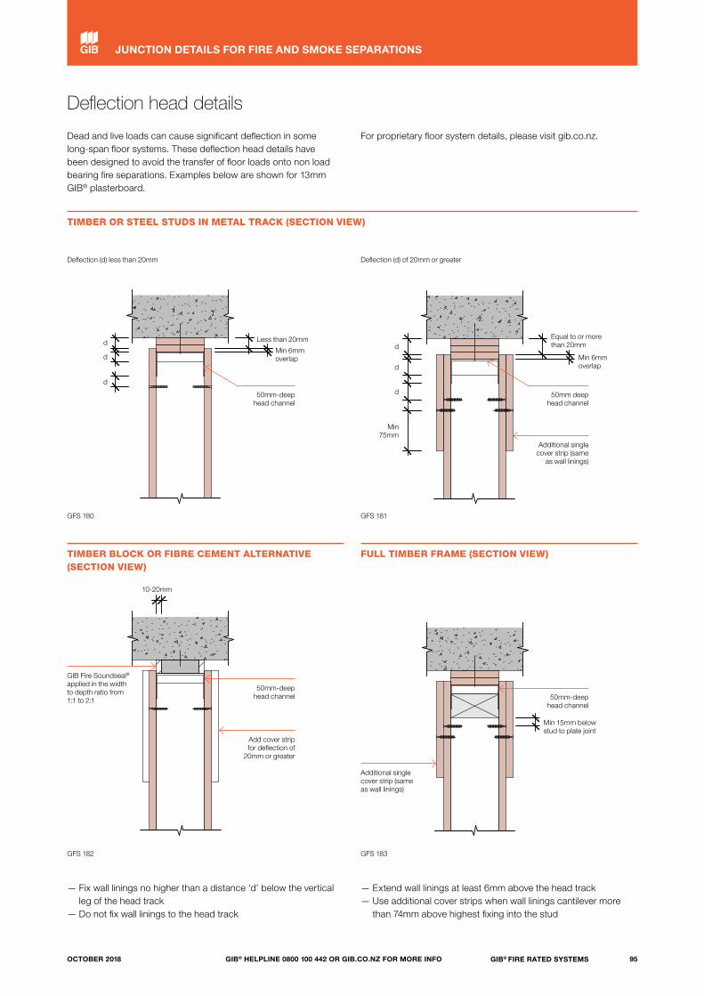
Deflection head details
Dead and live loads can cause significant deflection in some long-span floor systems. These deflection head details have been designed to avoid the transfer of floor loads onto non load bearing fire separations. Examples below are shown for 13mm GIB® plasterboard.
For proprietary floor system details, please visit gib.co.nz.
— Fix wall linings no higher than a distance ‘d’ below the vertical leg of the head track
— Do not fix wall linings to the head track
— Extend wall linings at least 6mm above the head track— Use additional cover strips when wall linings cantilever more
than 74mm above highest fixing into the stud
TIMBER OR STEEL STUDS IN METAL TRACK (SECTION VIEW)
TIMBER BLOCK OR FIBRE CEMENT ALTERNATIVE (SECTION VIEW)
FULL TIMBER FRAME (SECTION VIEW)
Deflection (d) less than 20mm Deflection (d) of 20mm or greater
GFS 180
GFS 182
GFS 181
GFS 183
50mm-deep head channel
50mm deep head channel
Additional single cover strip (same
as wall linings)
Less than 20mm Equal to or more than 20mm
Min 6mm overlap Min 6mm
overlap
d dd
d
dd
Min 75mm
10-20mm
50mm-deep head channel
Add cover strip for deflection of
20mm or greater
GIB Fire Soundseal® applied in the width to depth ratio from 1:1 to 2:1
Additional single cover strip (same as wall linings)
50mm-deep head channel
Min 15mm below stud to plate joint
95GIB® FIRE RATED SYSTEMSGIB® HELPLINE 0800 100 442 OR GIB.CO.NZ FOR MORE INFOOCTOBER 2018
JUNCTION DETAILS FOR FIRE AND SMOKE SEPARATIONS

X
Y
X
Y
Steel stud nogging and roof detail
STEEL STUD NOGGING DETAIL
When sheet end joints in steel stud systems are unavoidable, they are best formed over channels, placed on edge and face-fitted over studs with the legs removed. The example below shows 64mm x 30mm channel over steel studs.
Alternatively, use the Rondo FAST-FIX Nogging® system shown.
Nog detail using face-fixed metal channel Rondo FAST-FIX Nogging® installed using face-fix x 2-screw method
ROOF DETAIL (SECTION VIEW)
The linings are taken to the roof underlay or wire netting. Where the roofing fits within the stated limitations, no fire stopping is required in the profile of the roofing material.
Nog on edge from ex 64mm x 30mm BMT track. Stagger nogs by at least 400mm on opposite sides of the wall.
GFS 200
Where roofing profile dimension ‘x’ is less than 80mm or ‘y’ is less than 40mm, the fire separation is permitted to stop at the roof line
Roofing Fire stopping Fire-retardant membrane over wire netting
Fire separation wall
96 GIB® FIRE RATED SYSTEMS GIB® HELPLINE 0800 100 442 OR GIB.CO.NZ FOR MORE INFO OCTOBER 2018
JUNCTION DETAILS FOR FIRE AND SMOKE SEPARATIONS
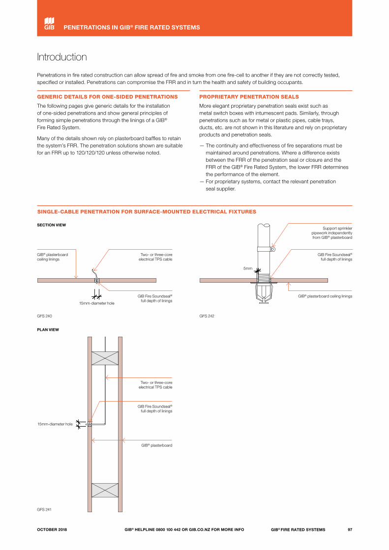
Introduction
Penetrations in fire rated construction can allow spread of fire and smoke from one fire-cell to another if they are not correctly tested, specified or installed. Penetrations can compromise the FRR and in turn the health and safety of building occupants.
GENERIC DETAILS FOR ONE-SIDED PENETRATIONS
The following pages give generic details for the installation of one-sided penetrations and show general principles of forming simple penetrations through the linings of a GIB® Fire Rated System.
Many of the details shown rely on plasterboard baffles to retain the system’s FRR. The penetration solutions shown are suitable for an FRR up to 120/120/120 unless otherwise noted.
PROPRIETARY PENETRATION SEALS
More elegant proprietary penetration seals exist such as metal switch boxes with intumescent pads. Similarly, through penetrations such as for metal or plastic pipes, cable trays, ducts, etc. are not shown in this literature and rely on proprietary products and penetration seals.
— The continuity and effectiveness of fire separations must be maintained around penetrations. Where a difference exists between the FRR of the penetration seal or closure and the FRR of the GIB® Fire Rated System, the lower FRR determines the performance of the element.
— For proprietary systems, contact the relevant penetration seal supplier.
SINGLE-CABLE PENETRATION FOR SURFACE-MOUNTED ELECTRICAL FIXTURES
GFS 240
GFS 241
GFS 242
SECTION VIEW
PLAN VIEW
GIB® plasterboard ceiling linings
15mm-diameter hole
15mm-diameter hole
5mm
Two- or three-core electrical TPS cable
GIB Fire Soundseal® full depth of linings
GIB® plasterboard
Two- or three-core electrical TPS cable
GIB Fire Soundseal® full depth of linings
Support sprinkler pipework independently from GIB® plasterboard
GIB Fire Soundseal® full depth of linings
GIB® plasterboard ceiling linings
97GIB® FIRE RATED SYSTEMSGIB® HELPLINE 0800 100 442 OR GIB.CO.NZ FOR MORE INFOOCTOBER 2018
PENETRATIONS IN GIB® FIRE RATED SYSTEMS
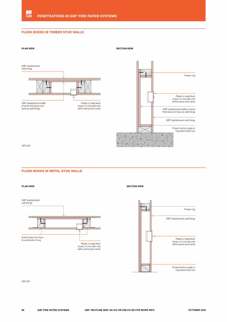
FLUSH BOXES IN TIMBER STUD WALLS
GFS 260
FLUSH BOXES IN METAL STUD WALLS
GFS 261
PLAN VIEW
PLAN VIEW
SECTION VIEW
SECTION VIEW
GIB® plasterboard baffle of same thickness and type as wall linings
Solid timber from floor to underside of nog
GIB® plasterboard wall linings
GIB® plasterboard wall linings
Plastic or steel flush boxes, to one side only within same stud cavity
Plastic or steel flush boxes, to one side only within same stud cavity
Timber nog
Timber nog
Plastic or steel flush boxes, to one side only within same stud cavity
Plastic or steel flush boxes, to one side only within same stud cavity
GIB® plasterboard baffle of same thickness and type as wall linings
GIB® plasterboard wall linings
GIB® plasterboard wall linings
Protect bottom plate or nog below flush box
Protect bottom plate or nog below flush box
98 GIB® FIRE RATED SYSTEMS GIB® HELPLINE 0800 100 442 OR GIB.CO.NZ FOR MORE INFO OCTOBER 2018
PENETRATIONS IN GIB® FIRE RATED SYSTEMS
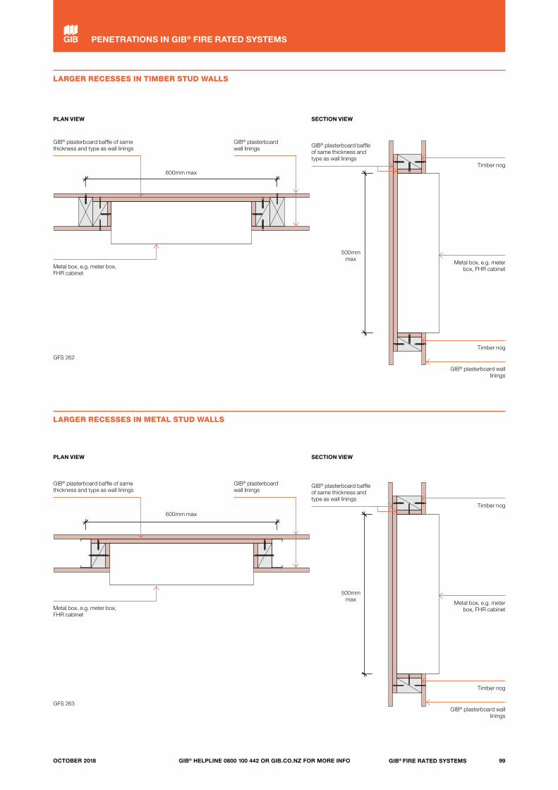
LARGER RECESSES IN TIMBER STUD WALLS
LARGER RECESSES IN METAL STUD WALLS
PLAN VIEW
PLAN VIEW
SECTION VIEW
SECTION VIEW
GFS 263
GFS 262
Metal box, e.g. meter box, FHR cabinet
Metal box, e.g. meter box, FHR cabinet
GIB® plasterboard baffle of same thickness and type as wall linings
GIB® plasterboard baffle of same thickness and type as wall linings
GIB® plasterboard baffle of same thickness and type as wall linings
GIB® plasterboard baffle of same thickness and type as wall linings
GIB® plasterboard wall linings
GIB® plasterboard wall linings
Timber nog
Timber nog
Timber nog
Timber nog
GIB® plasterboard wall linings
GIB® plasterboard wall linings
Metal box, e.g. meter box, FHR cabinet
Metal box, e.g. meter box, FHR cabinet
600mm max
600mm max
500mm max
500mm max
99GIB® FIRE RATED SYSTEMSGIB® HELPLINE 0800 100 442 OR GIB.CO.NZ FOR MORE INFOOCTOBER 2018
PENETRATIONS IN GIB® FIRE RATED SYSTEMS
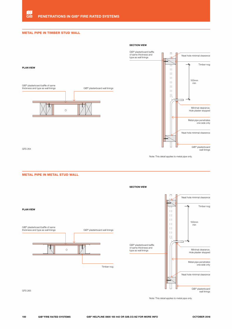
METAL PIPE IN TIMBER STUD WALL
GFS 264
GFS 265
METAL PIPE IN METAL STUD WALL
PLAN VIEW
PLAN VIEW
SECTION VIEW
SECTION VIEW
GIB® plasterboard baffle of same thickness and type as wall linings
GIB® plasterboard baffle of same thickness and type as wall linings
GIB® plasterboard wall linings
GIB® plasterboard wall linings
Timber nog
GIB® plasterboard baffle of same thickness and type as wall linings
GIB® plasterboard baffle of same thickness and type as wall linings
Timber nog
Timber nog
Minimal clearance. Hole plaster stopped
Minimal clearance. Hole plaster stopped
Metal pipe penetrates one side only
Metal pipe penetrates one side only
GIB® plasterboard wall linings
GIB® plasterboard wall linings
Note: This detail applies to metal pipe only.
Note: This detail applies to metal pipe only.
Neat hole minimal clearance
Neat hole minimal clearance
Neat hole minimal clearance
Neat hole minimal clearance
100mm min
100mm min
100 GIB® FIRE RATED SYSTEMS GIB® HELPLINE 0800 100 442 OR GIB.CO.NZ FOR MORE INFO OCTOBER 2018
PENETRATIONS IN GIB® FIRE RATED SYSTEMS

SUSPENDED CEILING (SECTION VIEW)
SPRING OR CLIP FIXED LIGHT FITTING (SECTION VIEW)
FRAME FIXED LIGHT FITTING (SECTION VIEW)
GFS 280
GFS 281
GFS 282
GIB® Fire Rated System Types GBFC, GBCJ or GBUC
Any suspended ceiling system with ties to fixed battens. Recessed light fittings may be installed conventionally including troffer pack modules (shown), recessed downlights or other light fittings as required
Floor/ceiling systems require one extra layer of GIB® plasterboard of same type and thickness as the ceiling lining. Universal systems are lined as per ceiling
Floor/ceiling systems require one extra layer of GIB® plasterboard of same type and thickness as the ceiling lining. Universal systems are lined as per ceiling
GIB® plasterboard as per ceiling linings
Cable penetration fire stopped (see detail GFS 241, page 97)
Floor
Floor
Board fixing centres: vertical sheets at 300mm centres, horizontal sheets
at 150mm centres
Timber joists fixed at 600mm centres
Light fitting module
Strongback fixed to dropper
GIB® plasterboard as per ceiling linings
Steel stud dropper 65mm x 34mm
Nogs ex steel stud fixed to dropper
Steel stud 65mm x 34mm
GIB® plasterboard
Diffuser
Framing
75mm x 50mm min. batten
Lighting module
101GIB® FIRE RATED SYSTEMSGIB® HELPLINE 0800 100 442 OR GIB.CO.NZ FOR MORE INFOOCTOBER 2018
PENETRATIONS IN GIB® FIRE RATED SYSTEMS

DESIGN STRATEGY
Resolve and specify fire rated service penetrations in the design office rather than on-site. Combine services as much as possible in ‘services highways’ or shafts which can themselves be fire rated, eliminating the need for many different and individual penetrations.
ENSURE FITNESS FOR PURPOSE
Fire test results for penetration seals, such as plastic pipe collars that have been tested in concrete, cannot be simply transferred to other types of construction such as framed construction lined with gypsum plasterboard.
Sometimes suppliers of penetration seals rely on overseas or local tests carried out on gypsum plasterboard assemblies with significantly greater fire resistance than what is claimed for the penetration seal. A penetration seal must be suitable for the construction type it is installed in. Check test reports and manufacturer’s information carefully.
SUPPORT PENETRATION SEALS
To erase doubt, ensure penetration seals are supported by framing around the aperture and not directly by gypsum plasterboard linings. Installation of additional framing members may be required.
Alternatively, an additional strip of plasterboard can be installed over the existing lining and supported by adjacent framing members. This option is suitable for penetration seals such as cable bundles, small metal pipes and plastic pipe collars.
When multiple services penetrate a fire rated wall above ceiling level, it is best practice to install a continuous strip of GIB® plasterboard at that location over the wall linings as illustrated below, providing local strengthening.
Penetration patches are not required when penetration seals are installed in one way universal (UW and UC) systems.
Heavy penetrating items such as cable trays and ducts must have separate supports, such as hangers to the floor above.
Firewall
Ceiling
Fix a second layer strip to accommodate multiple penetrations
above ceiling level
GIB® plasterboard patch to be same type as wall lining
Laminate cut-out to wall lining using 38mm x 10g
GIB® Grabber® Laminator Screw for fitting patch
around existing services
75mm min
Fix patch to framing with GIB® Grabber® drywall screws penetrating steel by no less
than 12mm or timber by no less than 20mm
102 GIB® FIRE RATED SYSTEMS GIB® HELPLINE 0800 100 442 OR GIB.CO.NZ FOR MORE INFO OCTOBER 2018
PROPRIETARY PENETRATION SEALS

103GIB® FIRE RATED SYSTEMSGIB® HELPLINE 0800 100 442 OR GIB.CO.NZ FOR MORE INFOOCTOBER 2018

DPC under framing
GIB® HandiBrac® positioned centrally
on bottom plate
Proprietary concrete anchor with 8kN uplift capacity
140mm x 45mm timber framing
STRUCTURAL STABILITY
In order to satisfy the requirements of NZBC Clause C6 – Structural Stability, designers must ensure that fire rated elements are supported by elements having at least the same FRR. Collapse of elements having a lesser FRR shall not cause the consequential collapse of elements required to have a higher FRR.
For example, a column must have at least the same structural adequacy rating as the floor it is supporting, and the same applies to a section of wall providing lateral support to a fire-cell boundary.
Note also that an FRR represents the result against a standard furnace test for fire resistance where a specimen is exposed from one side. A supporting element located entirely within a fire-cell will potentially be exposed to fire from multiple sides simultaneously. In this case, ‘universal’ or ‘one way’ lining protection needs to be provided to all relevant sides. If such an element provides lateral support, then the bracing element must be protected with a ‘universal’ or ‘one way’ lining system.
STABILITY OF BOUNDARY WALLS
When a building is located sufficiently close to a property boundary, an FRR is often required to manage the risk of fire spread to adjacent property. NZBC Clause B1 — Verification Method B1/VM1 provides guidelines for checking the lateral stability of fire rated boundary walls. The simplest and most commonly applied criterion is the ability to resist ‘a uniformly distributed face load of 0.5kPa in any direction’.
Buildings complying with Acceptable Solutions that do not mention post-fire stability do not need separate assessment for compliance with B1/VM1.
This means that low-risk single and small multi-unit dwellings and residential garages designed and constructed in accordance with Acceptable Solutions B1/AS1 and C/AS1 are exempt from separate B1/VM1 analysis.
For higher risk or more complex structures, such as public facilities, multi-storey buildings or portal frame industrial structures, specific design is required. The building designer must ensure that structural stability is maintained for the specified time of fire resistance in accordance with the provisions of B1/VM1. The solution will often require project-specific considerations and could involve fire rated return walls, a fire rated ceiling or cantilever external wall details.
SINGLE-STOREY, LIGHT TIMBER-FRAMED BOUNDARY FIREWALL
The following details have been developed for simple single-storey, light timber-framed structures that require design for structural stability as a consequence of fire.
The detail relies on bottom plate fixing and cantilever action of the wall to resist an imposed 0.5kPa face load in any direction.
The minimum requirements for concrete slab and timber-framing details, grade and treatment, are in accordance with the latest versions of NZS3604 and NZS3602.
— Walls with a height of 2.4m require a minimum stud size of nominally 140 x 45mm at 600mm centres.
— Walls with a height of 3.0m require a minimum stud size of nominally 140 x 45mm at 400mm centres.
— With the GIB HandiBrac®, use a proprietary concrete anchor with a minimum characteristic uplift capacity of 8kN, as verified by the supplier.
The required FRR is determined in accordance with NZBC Clause C Acceptable Solutions or Verification Method. If located more than 1m from the relevant boundary, check to see if a one way protection is permitted.
Select the relevant one way or two way FRR system and GIB® specification from this literature.
If a two way FRR is required, note that sheet joints and fastener heads in the GIB® plasterboard under the external cladding do not require stopping.
All cladding system types, including vertical profile metal cladding, must be separated from GIB® plasterboard by means of a flexible underlay and drained cavity system. Cladding details must otherwise comply with NZBC Clause E2.
Keep the GIB® plasterboard dry during installation and maintain the cladding system to ensure that the GIB® plasterboard remains dry in-service.
GIB® plasterboard behind an NZBC E2/AS1 compliant cladding system, drained cavity and flexible underlay, has a serviceable life in excess of 15 years and satisfies the requirements of NZBC Clause B2 — Durability for an external wall cladding.
Use claddings with exterior surface finish properties that fall within the limits set by NZBC Clause C Verification Method or Acceptable Solutions.
HOLD DOWN DETAIL (ALL STUDS)
104 GIB® FIRE RATED SYSTEMS GIB® HELPLINE 0800 100 442 OR GIB.CO.NZ FOR MORE INFO OCTOBER 2018
STABILITY OF FIRE RATED ELEMENTS
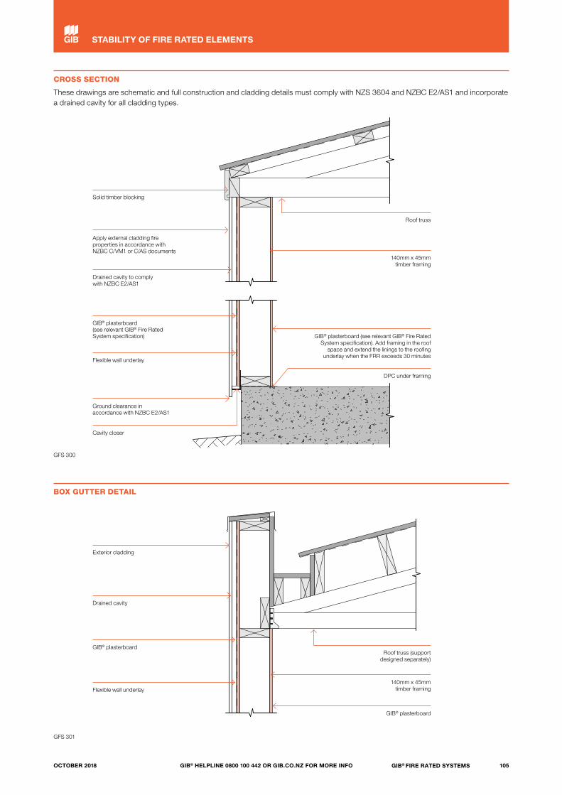
GFS 300
GFS 301
CROSS SECTION
These drawings are schematic and full construction and cladding details must comply with NZS 3604 and NZBC E2/AS1 and incorporate a drained cavity for all cladding types.
BOX GUTTER DETAIL
Solid timber blocking
Roof truss
140mm x 45mm timber framing
GIB® plasterboard (see relevant GIB® Fire Rated System specification). Add framing in the roof
space and extend the linings to the roofing underlay when the FRR exceeds 30 minutes
DPC under framing
GIB® plasterboard
140mm x 45mm timber framing
Roof truss (support designed separately)
Apply external cladding fire properties in accordance with NZBC C/VM1 or C/AS documents
Drained cavity to comply with NZBC E2/AS1
GIB® plasterboard (see relevant GIB® Fire Rated System specification)
Flexible wall underlay
Ground clearance in accordance with NZBC E2/AS1
Cavity closer
Exterior cladding
Drained cavity
GIB® plasterboard
Flexible wall underlay
105GIB® FIRE RATED SYSTEMSGIB® HELPLINE 0800 100 442 OR GIB.CO.NZ FOR MORE INFOOCTOBER 2018
STABILITY OF FIRE RATED ELEMENTS

Notes
106 GIB® FIRE RATED SYSTEMS GIB® HELPLINE 0800 100 442 OR GIB.CO.NZ FOR MORE INFO OCTOBER 2018
GIB® Fire Rated Systems, October 2018
Winstone Wallboards Ltd accepts no liability if the GIB® Fire Rated Systems and junction details are not installed in strict accordance with instructions contained in this publication.
USE ONLY THE CURRENT SPECIFICATION
This publication may be superseded by a new publication. Winstone Wallboards accepts no liability for reliance upon publications that have been superseded. You should check the GIB® website to ensure you are using the current publication. If you are unsure whether this is the current publication, simply call the GIB® Helpline on 0800 100 442.
SUBSTITUTION
GIB® Fire Rated Systems have been specifically designed and tested to achieve the listed FRR, STC and Rw stated for each system. To maintain the GIB® Product and System Warranty, all system components detailed in this publication must be used when specifying and installing GIB® Fire Rated Systems. You should check the GIB® website to ensure you are using the current publication.
TRADEMARKS
The names GIB®, GIB Fyreline®, GIB Ultraline®, GIB Toughline®, GIB Braceline®/GIB Noiseline®, GIB Aqualine®, GIB Nail®, GIB Tradeset®, GIB Plus 4®, GIB-Cove®, GIB Lite Blue®, GIB Fix®, GIB Quiet Stud®, GIB Rail®, GIB Barrierline®, GIB Fire Soundseal®, GIB Clip®, the colour mauve for GIB Toughline®, the colour blue for GIB Braceline®, the colour pink for GIB Fyreline®, the colour green for GIB Aqualine®, and the shield device are registered trademarks of Fletcher Building Holdings Limited.
COPYRIGHT
Copyright© Winstone Wallboards Ltd 2018. All of the material contained in this brochure, including all text, tables, charts, graphs, drawings, images and diagrams are protected by copyright. These materials may not be reproduced, adapted or transmitted in any form by any process, without the permission of Winstone Wallboards Ltd.
COUNTRY OF ORIGIN
We make GIB® plasterboard in New Zealand*, for New Zealand conditions, giving you 100% certainty.
*Note: GIB Barrierline® plasterboard is manufactured to Winstone Wallboards’ specific specification from a reputable overseas manufacturer.
Copyright© Winstone Wallboards Ltd, 2018.
107GIB® FIRE RATED SYSTEMSGIB® HELPLINE 0800 100 442 OR GIB.CO.NZ FOR MORE INFOOCTOBER 2018

FOR MORE INFORMATION VISIT
gib.co.nzOR CALL THE GIB® HELPLINE
0800 100 442
Octob
er 2018