fire resistant power cables
TRANSCRIPT
Address:
Marchants Industrial Centre, Mill Lane, Laughton, Lewes,
East Sussex, BN8 6AJ, UK
Tel: 44(0) 207 4195087
Fax: 44(0) 207 831 9489
E-mail:[email protected]
www.caledonian-cables.com
FIREFLEXFire ResistantPower Cables
& Control Cables
CaledonianAddress:
Marchants Industrial Centre, Mill Lane, Laughton, Lewes,
East Sussex, BN8 6AJ, UK
Tel: 44(0) 207 4195087
Fax: 44(0) 207 8319489
E-mail:[email protected]
www.caledonian-cables.co.uk
Addresessesesesesssesesssesesessssssesesessssssesesesesesesssesssssssesssssesssssesssessessesssssssssessssssessesessssesessssssssssssesssssssssessessssssssesssssseeesesssseeeeessssseeesessssseesseeeessssseesseeeesssseeeeeeeeessesssssssssssss:s:s:s:ssss:s:s:sssssssss:s:s:s:ssssssss:s:ssssss:sssss:s:s:s:s:sss:s:s::s:ssss::ss:s::s::s:sss::sssss::s:sss:ssss:sss:ssss:sssss::sssssss::sss:s::
MMMaMaMaMaMaMMaMaMaMMMMaMaMaMaaMaMMaMaMaMaMMaaMaMaMaMMMMaMaMaMaMaMaMaMMMaMaMaaMaMMMaMaMaMaMaMMMMMaaaMaaMaMaMaMMMMaMaMaMaaMaMMMMMMMaaMMMMMMaMaaMMMMMMMMaMaMaMMMMMMMMMaaaMMMMMMMaMaMMMMaaMMMMMMMaaaMaaMMMMMMaMaMaaaMMMMMaMaMaaMMMMaaaaMMMMMMaaMMMMaaaaMMMMMMMMMMaMMMMaaaaMaMaaMMMMMaMMMMaaaMMMMMaMaaaMMMMMMaaMMMMaMMMMMMMMaaaaMMaaaMMaarrrrrrrrrrrrrrrcrcrcrcrcrcrcrcrccrcrcrrrrrrrcrcrcrcrrrrrcrrrrcrrrrcrccrcrrcrcrcrcrcrcrccrcrrrrcrcrcrccr hahhhhahhhahahahhhhhhahahhhahahahhaahahahahaahhahaaaaaaaahannnnntttntntntntntntntntnnntnntntnnntnnntnntntntntnttnttssssssssss ss s s s s IIIIIInInnnInInInInnnnnddduddududududududdududududuududuuuuuuuuuuuduuduuuduuuuuuuuuuuduuduuuuuuuussssssststststtstststsstststsststststssttstststststststsstsssststsststststststssststsstsstsssts rrrriiiririrririirrrrrrrrr al Cennnnnnnnnnnnnnnnnntrtrrtrtrrrrrtrrrrtrrrrrtrrrrtrtrrtrrrrrrrtrrtrrtrrrtrrrtrtrrrtrtrrrrrrtrrrrtttttrrtttttttttrttttttttttttttrtttttttrrtttttrrrrtttrrrttttrrttrrrrreeeeeeeee,ee,ee,e,eeeeeee,e,e,ee,e,e,e,e,eee,e,ee,e,e,e,eeee,eee,eeeeee,eeee,e,e,eee,eee,e,e,eeeee,e,e,e,e,eeee,e,,e,,ee,,e,ee,,,e,eeeee,e,eee,,e,,eeeeeeee,e,,eee,,eeee,,,eee,,,,,,,,,,,,, MMMMMMMMMMMM MMMMMMMMMMMMMMMMMMMMMMMMMMMMMMMMMMMMMMMMMMMMMMMMMMMMMMMMMMMMMMMMMMMMMMMMMMMMMM MMMMMMMMMMMMMMMMMMMMMMMMMMMMMMMMMMMMMMMMMMMMMMMMMMMMMMMMMMM MMM MMMMMMMMMMM MMM iiiiiiiiililllliliiiiililllililiillillliillilililililliiliililiiililiiiliiililiilililililillllillllllllllllllllllllllllllllllllllllllllll
EEEEEEEEEaEaEaEaEaEEEEEEaEEaEEaEEEaEEaEaEaEaaEaEaEaaEaEaaEaaEaaEaaEaaEaaEEEaaaEEaassssstssttstsstsstststssstsstsstttts SSSSSS SSSSSSSSSuuususususuussussssususssssssssussssssssssssseseseseseseseseseseseessseeseseseseeseesseseeesessesesesseeseesessesessesseessseesssseesesexxxxxxxxxx,xxxx BN8 6666666666666666666666666666666666666666666666666666666666666666666666AAAAAAAJAJAJAJAJAJAAJAAJAJAAJAJAAAAAJAJAJAJAJAJAAAAAAAAJAJAJAJAJJAAJAJAJAJAAAJAJAJJAJAJAJAAJAJJAJAJJAJJJAJAAAAJAJAJAAJAJAJJAJAJAJJJAJJAJJJAJAAJJJJAAJJJAJJAAAJJAJJAJAJAJAAAAAJAJJAAAJAJAAAJAAJAAAAAAJAAAJAAAAAAAAAJJAAAAAAJJJAJJ,,, ,, ,,, , ,,, UKUKUKUKUKUUKUUKUKUUKUKUKUKUKUKUKUKUUKUKUKUKUKUKUUKUKUKUKUKUKUKUKUKKUKUUKUUKUKUKUKKKKUKKUKUKUKUKUKUKKUUKUKUKUUKUKUKUKUKUKUKUKKUKUUUUUKKUKUKKKKUKUKUUKUUKUKKUKUKUKKUKUKKUKUUUKUUUUUKUKKKUUUKKUKUUKKUKUKKKUKKKUKKUKKUKKKUKUKUUKUKUKKUUKKUKKKUKKUUUKUUUUUKUUKUUKKUUUUUKUUUUKKKUUUUKKKUUKUKKKUUKKKUUUKKUUKKUUUUUU
TTTTTTeTeTeTeTeTeTeTeeeeeeeeeelll:l:l:l:l:l:::l:l::l::l:l:l:l::l::l:ll:::l::::l: 444444444444444444444 444444444 44 4444 444444444444444444444444444444444(4(4(4(4(4(4(444444444444 0) 2077777777 4444444444444444444444444 444444 44444 44444444444444444444444444444444444444444444444444444 4 444 444444444444444444444444444441111111111111191919199191919191919199919199111111191919191991111111919199111111199919119919191919199911911991999191911119919191911119999911199911199119119119191911991195505050555550505050505505550000888878787878778787878777
FFFFFFFFFFFaFaFaFFaFaFFaFFaFFFF x: 44(4(4(4(4(4(4(((4(4(4((((((((((((((((((((((((((((((((((((((((0)0)0)0)0)0)0))0)0)0))0)0)0)0))0))0)))0))0))0))0))0)0)0)0)0)0)0)0)0)0)0)0)0)00))0)00))0)0)00)000))0)000)0)0)000)0)0)0)0)0)000)0)0)0)0)0)00)000)0)0)0000)0)0000)))0)0)000)0))00)000)0)))))0))))))0)0)))))))))))))) 222222222222222222222222222222222222222222222222 222222222 2222222222222222222222220000707000707070707070700000707070007000000000777 888 8 8 88888833333313113131313313131111111 99999999999 99999994444444884448484848484848484884488884888888884884888999999999999999999999999999999999999999999999
E-mmmmmmmmmmamamamamaamamamamamamamamaammmmmaamamamammmmamammmmmaaaammaammaaaaammamamaammaamaammamaaammaaammmmaaammmmaammmmaammmmmmammmmmamamaaamamamammmaaammmmaaaammmamaammmmmammmaaaamamaammmammmaiiiiilililiililliliiiililiiiiiilililiiiiiiiililliiiilliiilillililililililiil:s:s:s:sss:ssss:s:s:sss:s:ss:saalalalaalalalalllleeesesesesesessesssssss@@@@@@@@@c@c@c@c@c@@c@c@@c@@cc@c@@c@cccalalalalalaalaalalalllaaalalalalalalaaallalaalalalallllaaleedededededededededededeedeeddededededeededeeeddeddeededededdddeddedddededdedddedededdddededededededddedededdeddddedededeeddeddededdddddddddeddeddddddededdddededddddddeddddeeededdeddeeeeeedeeeeeeeeeeeeeeeeeeeeeeeeee oono ian--ccacacacacaacaaacacacacaaccacaaacacacaaacaccaaaacaccccccccacacccccaccccccacaacccacccaaccccccccccccccccccccccaccccccccccccaacccccccccacccacccccacaacaccccaaabbbbbbbblblblblbbbblblbblblblbbbblblbbbbblbblblbbblbbbbbblblbblblblbblblbbblblblllblbbllbllllleeeeeeeeeseseseseseeseeeeseeeeeseeesss
wwwwwwwwwwwwwwwwwwwwwwwwwwwwwwwwwwwwwwww.w.ww.w.w.w.w..ccccacacacacacacacacaacacacaaccaalllllelelelleleleleeeeeeddoddodododododododdooododododdodoodoodoododoooooooooooodooooodoodooooooonnnininiinninnininniiiiiiniiniiinnniiiininiiniinininininniniininininniinininininnininnnnnnninininiinnnnnnninnnnnnnnnnnnnnnnnnnnnnnnnnnnnnnnnnnnnnnnnnnnnnnnnnnnnnnnn aaanaa -cabbbbbbbbbbbbbbbbbbbbbbbbbbbbbbbbbbbbbbbbbbbbbbbbbbbbbbbbbbbbbbbbbbbbbbbbbleellllelllleleleeeleeleleleleeeleleeeeleelllelllelllellelleeeeeeeeleeeeessssssss.s.ssssss.ssssssss.s.sss.ssssss.s.s.s.s.s.ss..s...s..ssss cccccccccccccccococococcccocccoccccccococococ mmmm
FFIRIREEFFFirFire e ReRessiissPoPowewer Car Cabbllee
&& Contr Control Caol Cabbllee

Table Of cOnTenTs
fire Resistant Power & control cables450/750V Mica+LSZH Insulated Power Cables (Single Core).............................................................................25 600/1000V Mica+LSZH Insulated Power Cables (Single Core)...........................................................................25 300/500V Mica+XLPE Insulated, LSZH Sheathed Power Cables (Single Core)................................................ 30600/1000V Mica+XLPE Insulated, LSZH Sheathed Power Cables (Single Core)..............................................33600/1000V Mica+XLPE Insulated, Armoured LSZH Sheathed Power Cables (Single Core).............................38300/500V Mica+XLPE Insulated, LSZH Sheathed Power Cables (2-4 Cores)................................................... 42600/1000V Mica+XLPE Insulated, LSZH Sheathed Power Cables (2-4 Cores & Multicore).............................. 46300/500V SR Insulated Control Cables (2-4 Cores)........................................................................................... 53300/500V SR Insulated & Overall Screened Control Cables (2-4 Cores & Multicore)..........................................60300/500V Mica+SR Insulated & Overall Screened Control Cables (2-4 Cores & Multicore).........................6450/750V SR Insulated Control Cables (2-5 Cores)........................................................................................69450/750V SR Insulated & Overall Screened Control Cables (1-4 Cores & Multicore)...................................73600/1000V SR Insulated Flexibles Control Cables........................................................................................81 Type Codes For Fire Resistant Power & Control Cables...................................................................................86

ADDISON
Caledonian2
fiRe ResisTanT cables
In all fire disasters, fire smoke, heat and toxic fumes are the main obstacles to safe evacuation of a building or area. A major contribution towards overcoming these hazards is the use of fire resistant and non-halogenated cables.
Caledonian fire resistant cables, branded under Fireflex, provide the following features:
Fire resistance
Long-term circuit integrity in a fire
Minimum smoke emission
Flame retardance
Reduced fire propagation
Zero halogen
Fireflex cables are mainly used in the wiring of:
Fire resistant safety circuits
Public address and emergency voice communication systems in high-rise building
Control and instrumentation services in industrial, commercial and residential complexes
High-temperature installation conditions
cable cOnsTRUcTiOn
Fireflex cables have been developed to maintain circuit integrity in a fire and to ensure maximum safe evacuation of personnel with no detrimental effects like toxic gases or smoke.
Fireflex cables are constructed in the following typical design:
Solid/stranded annealed copper conductor
Glass mica tape/silicone rubber as flame barrier
XLPE/silicone rubber as insulation
LSZH/flame retardant PVC as sheath
Fireflex cables are offered in either single core, multicore or multi-pair constructions. The insulation material can be elastomeric(EPR, SR), thermosetting (XLPE, LSZH) or thermoplastic (EVA, PVC) to meet different stringent environment requirement. The cables may be armoured or braided, with or without metallic screen, depending on different applications. Caledonian can provide PE, PU, PVC, SHF1, SHF2 or LSZH materials as outer sheath for different applications.
inTeRnaTiOnal sTanDaRD cOMPliance
The fire resistant cables manufactured by caledonian comply with either one or combination of the following standards.
What is fire Resistance
In a fire, the electrical systems must be able to keep functioning for a suitable length of time. This is particularly important for safety equipments used in emergency ventilation, emergency lighting, and

www.caledonian-cables.co.uk www.addison-cables.com
Caledonian
3ADDISON
Fireflex Fire Resistant Cables
alarm systems, together with the power supply to transport facilities and elevators. Fire resistance means that the cable or the cable system where the cable is installed is capable to continue to operate even in case of fire for a specific period of time from 30 to 180 minutes.
Circuit integrity (Insulation integrity) refers to tests for the cables only. This is denoted by FE180 in some European countries such as Germany and Belgium. Functional integrity refers to tests on cables and systems (ladders, cable tray, clamps etc). It is denoted by E30, E60, E90 indicating the cable resistance for 30, 60 and 90 minutes according to a specific test and different installation systems.
The functional integrity and the circuit integrity are not related in any way as regards their content. The former is a system test and the circuit (insulation) integrity is an individual cable test. The integrated system test for functional integrity is regarded as a technical benchmark in the cable industry.
DesiGn sTanDaRD in accORDance WiTH DiffeRenT sTanDaRDs
BS 7629-1:2008 – Electric cables. Specification for 300/500V fire resistant screened cables having low emission of smoke and corrosive gases when affected by fire. Multicore and multipair cables.
This standard apply to cables with thermosetting insulation of rated voltage 300/500V which conform to the performance requirements for cables required to maintain limited circuit integrity under those fire conditions of BS 6387 specified as B, W and X. Those cables are intended for use in fire alarm and emergency lighting applications.
The cables are suitable for operation at a maximum sustained conductor temperature of 70°C although the insulation is suitable for operation at higher temperatures. Use at a temperature not exceeding 90°C is allowed for terminations within an enclosure providing the cable conductor temperature outside the enclosure does not exceed 70°C.
The standards apply to cables with a rated voltage of 300/500V, and-two, three and four-core circular cables with uninsulated circuit protective conductor-7,12 or 19 core with an uninsulated drain wire-1,2,5,10,20 pairs having a collective metallic layer and drain wire.
They contain a metallic layer which provides electrostatic screening.
BS 7846:2009 – Electric cables. Thermosetting insulated, armoured, fire resistant cables of rated voltage 600/1000V, having low emission to smoke and corrosive gases when affected by fire.
Some circuits requiring an equivalent level of fire resistance need to be designed for larger cables than are found in BS 7629-1. Such circuits may be for the main emergency supply, fire fighting lifts, sprinkler system and water pumps, smoke extraction fans, fire shutters or smoke dampers. These larger cables are standardized in BS 7846 which covers the size range and LSZH performance under BS 6724. Through the use of mica tape to supplement the insulation, the cables can pass BS 6387 CWZ and additionally the ‘standard’ or ‘enhanced’ grade as specified in BS 5839-1.
The cables are intended for use in fixed installations in industrial areas, buildings and similar

ADDISON
Caledonian4
applications, where maintenance of power supply during a fire is essential and where the evolution of smoke and corrosive gases must be kept to a minimum.
The circuit integrity performance under fire conditions is assessed on the basis of various tests where resistance to fire, resistance to fire with water, and resistance to fire with mechanical shock are assessed separately or in combination. The cables are designated by the following categories:
Category F1- resistance to fire aloneCategory F2- resistance to fire, resistance to fire with water, resistance to fire with mechanical shock, assessed separately.Category F3- resistance to fire with mechanical shock and water assessed in combination. The cables are wire armoured and -two, three, four and five-core stranded copper conductor-multicore auxiliary stranded copper conductor.
BS EN 60702 – Mineral insulated cables with a rated voltage not exceeding 750V.
BS EN 60702-1:2002 applies to mineral insulated general wiring cables with copper or copper alloy sheath and copper conductors and with rated voltage of 500V (light duty grade) and 750V(heavy duty grade). Provision is made for a corrosion resistant extruded outer covering over the copper sheath, when required. The standard sets out requirements for the optional outer covering, which includes requirements for halogen free covering and the thickness of the covering. The standard includes routine tests including a spark test on the outer covering. Sample tests includes such as flame retardance, emission of acidic and corrosive gases and smoke emission. Type tests such as fire resistance are included.
Mineral insulated cables are extremely resistant but rigid and a particular care has to be paid during installation to prevent moisture absorption by the mineral oxide.
500V grade cable includes the following conductor sizes:- single and twin conductor cables up to 4mmsq csa- three, four and seven conductor cables up to 2.5mmsq csa
750V grade cable provides for:- single conductor cables up to 400mmsq csa- two, three and four conductor cables up to 25mmsq csa- seven conductor cables up to 4mmsq csa- twelve conductor cables up to 2.5mmsq csa- nineteen conductor cables up to 1.5mmsq csa

www.caledonian-cables.co.uk www.addison-cables.com
Caledonian
5ADDISON
Fireflex Fire Resistant Cables
The fire related properties by the cable standards are summarised in the following table:cable standard and type fire related properties
BS 7629
Thermosetting insulatedcables with limited circuitintegrity when affected by fire
BS EN 50265-2-1
BS EN 50268-2
BS 6387 Cat B, W & X
BS EN 50267-2-1
Tests on electric cables under f ire conditions - single core cable.Measurement of smoke density of electric cables burning under defined conditions.Fire burning under defined conditions.Performance requirements for cables required to maintain integrity under fire conditions.Gases evolved during combustion of electric cables.
BS 7846
600/1000 V armouredelectric cables having low emissions of smoke and corrosive gases when affected by fire
BS EN 50265-2-1
BS EN 50266-2-4
BS EN 50268-2
BS EN 50267-2-1
BS 7846 Cat F1, F2 or F3
Tests on electric cables under f ire conditions - single core cable.Tests on electric cables under f ire conditions - bunched cables.Measurement of smoke density of electric cables burning under defined conditions.Gases evolved during combustion of electric cables.Performance requirements for cables required to maintain integrity under fire conditions.
BS EN 60702
Mineral insulated cables with a rated voltage not exceeding 750V
BS EN 50265-2-1
BS EN 50268-2 (for zero-halogen coverings)
BS EN 50267-2-1(for zero-halogen coverings)BS 6387 Cat C, W &Z
Tests on electric cables under f ire conditions - single core cable.Measurement of smoke density of electric cables burning under defined conditions.Gases evolved during combustion of electric cables.Performance requirements for cables required to maintain integrity under fire conditions.
ADDISON
Caledonian6
cODe Of PRacTice in accORDance WiTH DiffeRenT sTanDaRDs
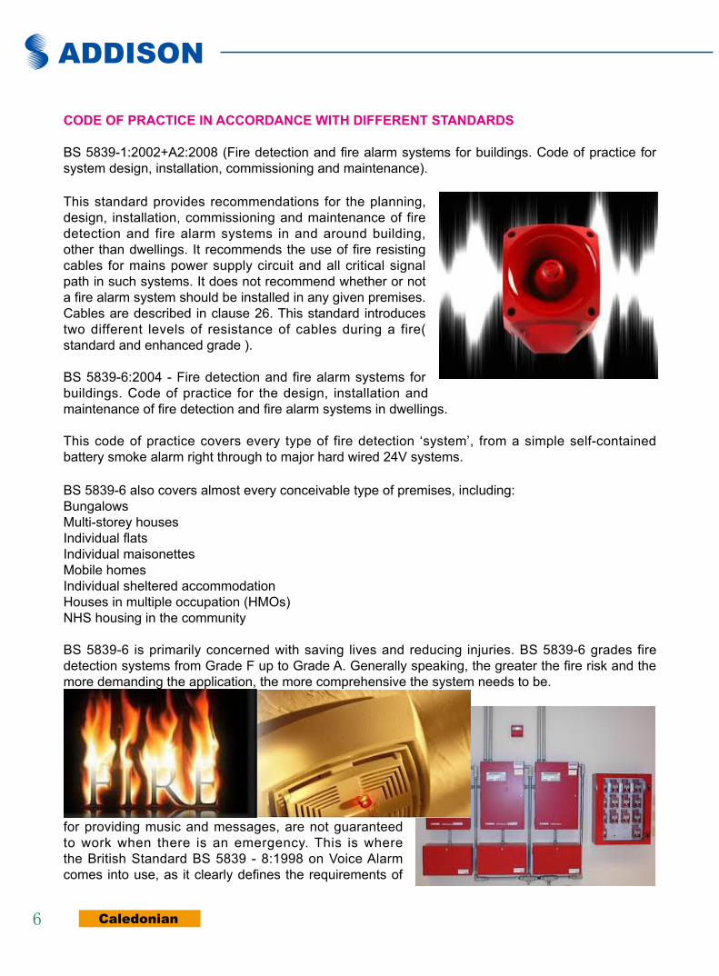
BS 5839-1:2002+A2:2008 (Fire detection and fire alarm systems for buildings. Code of practice for system design, installation, commissioning and maintenance).
This standard provides recommendations for the planning, design, installation, commissioning and maintenance of fire detection and fire alarm systems in and around building, other than dwellings. It recommends the use of fire resisting cables for mains power supply circuit and all critical signal path in such systems. It does not recommend whether or not a fire alarm system should be installed in any given premises. Cables are described in clause 26. This standard introduces two different levels of resistance of cables during a fire( standard and enhanced grade ).
BS 5839-6:2004 - Fire detection and fire alarm systems for buildings. Code of practice for the design, installation and maintenance of fire detection and fire alarm systems in dwellings.
This code of practice covers every type of fire detection ‘system’, from a simple self-contained battery smoke alarm right through to major hard wired 24V systems.
BS 5839-6 also covers almost every conceivable type of premises, including:BungalowsMulti-storey housesIndividual flatsIndividual maisonettesMobile homesIndividual sheltered accommodationHouses in multiple occupation (HMOs)NHS housing in the community
BS 5839-6 is primarily concerned with saving lives and reducing injuries. BS 5839-6 grades fire detection systems from Grade F up to Grade A. Generally speaking, the greater the fire risk and the more demanding the application, the more comprehensive the system needs to be.
BS 5839-8:2008 - Fire detection and fire alarm systems for buildings. Code of practice for the design, installation, commissioning and maintenance of voice alarm systems.
Many people believe they can simply use their PA system to provide a voice message in the event of an emergency like a fire. Unfortunately PA systems, whilst very good for providing music and messages, are not guaranteed to work when there is an emergency. This is where the British Standard BS 5839 - 8:1998 on Voice Alarm comes into use, as it clearly defines the requirements of

www.caledonian-cables.co.uk www.addison-cables.com
Caledonian
7ADDISON
Fireflex Fire Resistant Cables
a true VA system. A true VA system is a highly secure public address system which has the following features;
-All internal and external circuits are monitored for faults-A minimum battery back up of 24 hours standby and 30 minutes alarm.-A monitored secure link to a fire alarm panel-A number of pre-recorded emergency messages-Incorporates an emergency ‘firemans’ microphone
BS 5839-9:2011 - Fire detection and fire alarm systems for buildings. Code of practice for the design, installation, commissioning and maintenance of emergency voice communication systems.
An emergency voice communication systems(EVCS) is a fixed, secure, bi-directional, full duplex voice communication system to assist fire fighters in an emergency in high rise buildings or large sites where radio communication may not work, and covers the operation of both fire telephones and disabled refuge systems. Where both systems are fitted to a building, Bs5839-9 specifies these should be a single system.
BS 5266-1:2005 - Emergency lighting. Code of practice for the emergency lighting of premises.
The purpose of emergency lighting, anti-panic lighting and standby lighting is to ensure that the main fire exit routes from a building or open and high risk areas are sufficiently lit in the case of a mains failure, in order to allow persons to safely evacuate the areas or premises. Manual fire alarm points, first aid points, fire fighting and safety equipment should also be clearly lit, so that it can be clearly identified.
Cables installed for these systems have to withstand to fire for at least 60 minutes according to BS EN 50200.
BS 8519:2010- Selection and installation of fire resistant power and control cable systems for life safety and fire fighting applications. Code of practice.
BS 8519 was introduced specifically to apply only to large and complex buildings and has been widely welcomed within the industry. The new standard offers guidance for the selection of fire resistant power and control cables in life safety and firefighting systems such as smoke barriers, sprinkler systems, fire fighting and evacuation lift supplies. Consequently, BS 8519 should increase the protection of emergency and fire personnel, as well as evacuees who may be inside a large or complex building when fire breaks out.
ciRcUiT (insUlaTiOn) inTeGRiTy in accORDance WiTH DiffeRenT sTanDaRDs
circuit (insulation) integrity in accordance with iec 60331 IEC 60331 specifies tests for electric cable for circuit integrity under fire conditions. It is divided in following parts that describe the test modes, the conditions, and the equipment to use. The test was originally carried out only in fire alone for a period of 180 minutes at a temperature of 750°C.
ADDISON
Caledonian8
To better simulate the real fire conditions, with mechanical stresses due to the fall of materials and with the presence of water, the testing conditions have been modified by changing the duration, increasing the temperature of the flame and by adding mechanical stresses and water spray.
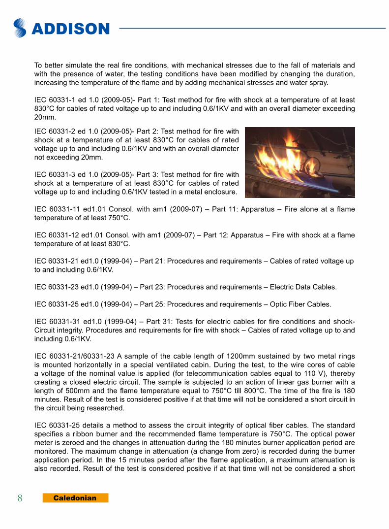
IEC 60331-1 ed 1.0 (2009-05)- Part 1: Test method for fire with shock at a temperature of at least 830°C for cables of rated voltage up to and including 0.6/1KV and with an overall diameter exceeding 20mm.
IEC 60331-2 ed 1.0 (2009-05)- Part 2: Test method for fire with shock at a temperature of at least 830°C for cables of rated voltage up to and including 0.6/1KV and with an overall diameter not exceeding 20mm.
IEC 60331-3 ed 1.0 (2009-05)- Part 3: Test method for fire with shock at a temperature of at least 830°C for cables of rated voltage up to and including 0.6/1KV tested in a metal enclosure.
IEC 60331-11 ed1.01 Consol. with am1 (2009-07) – Part 11: Apparatus – Fire alone at a flame temperature of at least 750°C.
IEC 60331-12 ed1.01 Consol. with am1 (2009-07) – Part 12: Apparatus – Fire with shock at a flame temperature of at least 830°C.
IEC 60331-21 ed1.0 (1999-04) – Part 21: Procedures and requirements – Cables of rated voltage up to and including 0.6/1KV.
IEC 60331-23 ed1.0 (1999-04) – Part 23: Procedures and requirements – Electric Data Cables.
IEC 60331-25 ed1.0 (1999-04) – Part 25: Procedures and requirements – Optic Fiber Cables.
IEC 60331-31 ed1.0 (1999-04) – Part 31: Tests for electric cables for fire conditions and shock- Circuit integrity. Procedures and requirements for fire with shock – Cables of rated voltage up to and including 0.6/1KV.
IEC 60331-21/60331-23 A sample of the cable length of 1200mm sustained by two metal rings is mounted horizontally in a special ventilated cabin. During the test, to the wire cores of cable a voltage of the nominal value is applied (for telecommunication cables equal to 110 V), thereby creating a closed electric circuit. The sample is subjected to an action of linear gas burner with a length of 500mm and the flame temperature equal to 750°C till 800°C. The time of the fire is 180 minutes. Result of the test is considered positive if at that time will not be considered a short circuit in the circuit being researched.
IEC 60331-25 details a method to assess the circuit integrity of optical fiber cables. The standard specifies a ribbon burner and the recommended flame temperature is 750°C. The optical power meter is zeroed and the changes in attenuation during the 180 minutes burner application period are monitored. The maximum change in attenuation (a change from zero) is recorded during the burner application period. In the 15 minutes period after the flame application, a maximum attenuation is also recorded. Result of the test is considered positive if at that time will not be considered a short
www.caledonian-cables.co.uk www.addison-cables.com
Caledonian
9ADDISON
Fireflex Fire Resistant Cables
circuit in the circuit being tested.
IEC 60331-31 applies to the cables with a diameter greater than 20mm, and introduces the standards and procedures for testing of cables exposed to fire and mechanical shock (equipment according to 60331-12). The test sample provides cable fragment length at least 1500mm. Bent wire on the U-shaped with a radius equal to the smallest permissible by the manufacturer, is mounted on a metal assay ladder. During the study, through all the cable wires is passed current with rated voltage and these cables are subjected to fire during 120min, where fire source is a gas burner set in conformity with standards, as well the mechanical shock of the 5 minutes interval. Result of the test is considered positive if at that time will not be considered a short circuit in the circuit being tested.
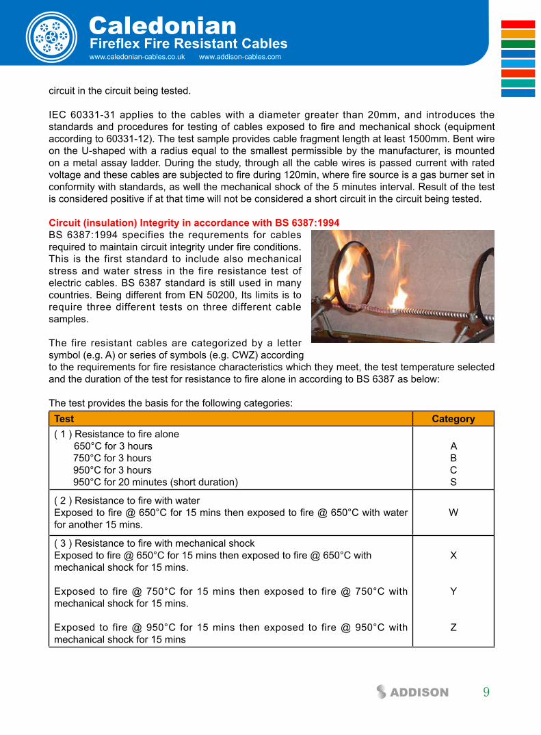
circuit (insulation) integrity in accordance with bs 6387:1994BS 6387:1994 specifies the requrements for cables required to maintain circuit integrity under fire conditions. This is the first standard to include also mechanical stress and water stress in the fire resistance test of electric cables. BS 6387 standard is still used in many countries. Being different from EN 50200, Its limits is to require three different tests on three different cable samples.
The fire resistant cables are categorized by a letter symbol (e.g. A) or series of symbols (e.g. CWZ) according to the requirements for fire resistance characteristics which they meet, the test temperature selected and the duration of the test for resistance to fire alone in according to BS 6387 as below:
The test provides the basis for the following categories:Test category( 1 ) Resistance to fire alone
650°C for 3 hours 750°C for 3 hours 950°C for 3 hours 950°C for 20 minutes (short duration)
ABCS
( 2 ) Resistance to fire with water Exposed to fire @ 650°C for 15 mins then exposed to fire @ 650°C with water for another 15 mins.
W
( 3 ) Resistance to fire with mechanical shockExposed to fire @ 650°C for 15 mins then exposed to fire @ 650°C with mechanical shock for 15 mins.
Exposed to fire @ 750°C for 15 mins then exposed to fire @ 750°C with mechanical shock for 15 mins.
Exposed to fire @ 950°C for 15 mins then exposed to fire @ 950°C with mechanical shock for 15 mins
X
Y
Z

ADDISON
Caledonian10
The most common test comprises the three categories C, W and Z.–Category C is a fire resistance test in which the cable is exposed to a fire at a temperature of 950°C with a duration of 3 hours. under realistic conditions.– Category W is a fire and water resistance test in which the cable is exposed to a fire at a temperature of 650°C and then for another 15 minutes to fire with water that is poured over the area around the cable. This simulates effect of water from a sprinkler that is activated during the fire. -Category Z is a fire and mechanical stroke test in which the cable is installed in a defined manner on a vertical wall with three cable clips and subject to heat from a gas burner; mechanical shock is simulated by striking the cable with a hammer. The cable is exposed to a fire at a temperature of 950°C and then for another 15 minutes to fire with mechanical shock at a frequency of 2 strikes per minute.
During testing in all three categories, the cable is connected to a 400V three-phase power supply protected with a 3 A fuse on each phase. The test is regarded as successful if none of the fuses blow during the test period.
circuit (insulation) integrity in accordance with en 50200:2006 EN 50200:2006 defines method of test for resistance to fire of unprotected small cables (up to 20mm) for use in emergency circuits. In the adapted chamber is mounted a cable sample with a length of 1200mm, to which wire cores during the test a nominal value voltage is applied, creating thereby a closed circuit. During the test the cable is subjected to actions of the fire at conventional temperature 842°C and mechanical stroke for a specified period of time. The measured time of proper functioning of the cable corresponds to the so-called cable fire resistance class PH, which is also mentioned in the standard PN-B-02851-1 - Fire resistance tests of elements of buildings (Test method for thin wires with an outside diameter not greater than 20mm).
The test duration is expressed in minutes and is recorded in the following classification: Test cattegoryFlame exposure for 15 minutes PH 15 Flame exposure for 30 minutes PH 30 Flame exposure for 60 minutes PH 60Flame exposure for 90 minutes PH 90Flame exposure for 120 minutes PH 120
EN 50200 annex E also foresees the water stress (fire, mechanical shock & water spray), as previously provided by BS 8434-1 standard. EN 50200 is similar to IEC 60331-2. Being different from BS 6387, EN 50200 test the same samples simultaneously stressed by the flame action, by the mechanical shock and by water spray.
circuit (insulation) integrity in accordance with en 50362:2003 EN 50362:2003 / BS EN 50362:2003 / DIN EN 50362:2003 / CEI EN 50362:2003 (CEI 20-36/5-0) defines method of test for resistance to fire of larger unprotected power and control cables for use in emergency circuits. This standard provides the same tests foreseen by IEC 60331-31 standards. (Flame Temperature of 830°C).
www.caledonian-cables.co.uk www.addison-cables.com
Caledonian
11ADDISON
Fireflex Fire Resistant Cables
circuit (insulation) integrity in accordance with bs 5839-1:2002The new edition of BS 5839-1:2002 (Fire detection and fire alarm systems for buildings. Code of practice for system design, installation, commissioning and maintenance) describes two level of fire performance for fire rated cabling for fire alarm system: Standard Grade and Enhanced Grade. In order to confirm the compliance of the cable to both categories, BS 5839-1 refers to EN 50200 and BS 8434-2003 Part 1 & 2. ( Method of tests for the assessmeent of fire integrity of electricity cables).These tests are carried out to verify the circuit integrity of small cables exposed to flame, mechanical shock and water in accordance with the new fire alarm code of practice.
Standard Grade clause 26.2dMaintenance of circuit integrity: BS 8434-1:2003 at 830°C for 30 minutes, 15 minutes with fire and mechanical shock plus15 minutes with fire, mechanical shock and water.BS EN 50200 PH3030 minutes at 830°C with fire and mechanical shock
Enhanced Standard Grade clause 26.2eMaintenance of circuit integrity: BS 8434-2:2003 at 930°C for 120 minutes, 60 minutes with fire and mechanical shock plus60 minutes with fire, mechanical shock and water.BS EN 50200 PH120 (improved)120 minutes at 830°C with fire and mechanical shock
circuit (insulation) integrity in accordance with bs 8434-1:2003 & bs 8434-2:2003 + a2:2009BS 8434- Methods of test for assessment of the fire integrity of electric cables Part1: Test for unprotected small cables for use in emergency circuits - BS EN 50200 with the addition of water spray. Part 2: Test for unprotected small cables for use in emergency circuits- BS EN 50200 with a 930°C flame and with water spray.
BS 8434-1:2003 defines test which is equivalent to BS EN 50200 with a 830°C flame and water spray. The cable is stressed by the flame at 830°C with mechanical shocks for 15 minutes and further 15 minutes with the addition of water spray. BS 8434-2:2003 defines test which is equivalent to BS EN 50200 with a 930°C flame and water spray. The cable is stressed by the flame at 930°C with mechanical shocks for 60 minutes and further 60 minutes with the addition of water spray. The tests for BS 8434-2 have not been covered in the BS EN 50200 standard yet and are still in force.
circuit (insulation) integrity in accordance with bs 8491:2008BS8491:2008 Method for assessment of fire integrity of large diameter power cables for use as components for smoke and heat control systems and certain other active fire safety systems. This standard is related to cables included in BS 7346-6 and certain other active fire safety systems. It is applicable to cables of rated voltage not exceeding 600/1000V and overall diameter greater than 20mm. The test method in BS 8491-2008 includes subjecting the cable under test to radiation via direct impingement corresponding to a constant temperature attack of 842°C, to direct mechanical impacts corresponding to a force of approximately 10N and to direct application of a water jet simulating a water fire fighting jet. The test method given in this standard includes three different test durations to allow testing of cables intended for different applications.

ADDISON
Caledonian12
circuit (insulation) integrity in accordance with Din VDe 0472-814 DIN VDE 0472-814:1991 - Testing of cables. wires and flexible cords; continuance of insulation effect under fire conditions.
A test fire is applied horizontally from a distance of 60cm to a single suspended cable during a specified time. The test is passed when there was continuous circuit integrity and no extremely increased attenuation values during and after the test respectively. For instance FE 90 cables can endure at least 90 minutes, „FE“ stands for flame exposure. The fire test with circuit integrity shows how many minutes a mechanically unstressed connection at a flame exposure of minimum 750°C keeps minimum insulation efficiency (circuit integrity) in a dry environment.Similar standard is IEC 60331 (FE) and BS 6387 Cat C. This is a fire test for insulation integrity without any mechanical and water stress.
circuit (insulation) integrity in accordance with nbn c 30-004 (cat. f3) NB N C 32 004 – Fire Resistance of electric cables. Classification and test method. The cable is stressed by the flame at 900°C with mechanical shocks every 30 seconds for a duration of 3 hours. The cable is deemed to pass the test if the current leakage does not exceed 1 amp per conductor. The test must be passed by 4 successive samples.
circuit (insulation) integrity in accordance with ss299-1 SS299-1 Fire resistant cables - Performance requirements for cables required to maintain circuit integrity under fire conditions.
circuit (insulation) integrity in accordance with cei 20-36/2-1CEI 20-36/2-1 Tests for electric cables under fire conditions-Circuit integrity - Part 21: Procedures and requirements- Cables of rated voltage up to and including 0.6/1KV.This is equivalent to IEC 60331-21.
circuit (insulation) integrity in accordance with cei 20-36/4-0CEI 20-36/4-0 Method of test for fire resistance of small cables unprotected for use in emergency circuits. This is equivalent to CEI EN 50200.
circuit (insulation) integrity in accordance with nf c32-070-2.3(cR1)The cable is installed in a stainless steel conduit and heated to 920°C ± 20°C according to a specified time curve. A voltage of 500 V AC or 1,000 V AC respectively is applied to the cable. To simulate mechanical shock, a small hammer strikes the pipe at a frequency of 2 strikes / min.
sysTeM ciRcUiT (fUncTiOnal) inTeGRiTy in accORDance WiTH DiffeRenT sTanDaRDs
system circuit (functional) integrity in accordance with Din 4102-12Maintaining the function of electrical cable during the fire, defined as the concept of cable system is characterized by the German DIN 4102, part 12. DIN 4101-12 is a testing for functional integrity of entire electrical cable systems together with fastener components and shall be considered as the most rigorous, but on the other hand, as most closely simulating the real fire conditions,
www.caledonian-cables.co.uk www.addison-cables.com
Caledonian
13ADDISON
Fireflex Fire Resistant Cables
DIN 4102-12 defines the requirements and testing method for fire resistance of electric cable system required to maintain circuit integrity. The standard defines testing for the functionality of so-called cable set, which consists of a group set of power cables, telecommunications, data cables etc. to be fixed to the support structure consisting of channels, ladders, cable tray ,items to hang, handles, etc. Cables attached to this structure are powered by their work voltage. Functional integrity will be tested for short-circuit of insulation or discontinuity of any wire core.
DIN 4102-12 is a realistic fire-chamber testing with minimum dimensions 2 x 3 x 2.5 m. (width/length/height). A complete cable installation is tested under realistic conditions. The effects of thermal expansion and mechanical load during a fire are taken into account. The temperature must follow the standard fire curve (ETK): At E 90, the system is tested for 90 minutes, with a flame temperatures reaching up to 1000°C during the test. The cable is installed in a furnace and mounted with cable trays and cable clips with guides. A voltage of 400 V AC is applied to the cable (or 110 V AC for telecommunications cables)There are three categories of function maintenance as follows: E30 - cable system function maintenance in case of fire for 30 minutesE60 - cable system function maintenance in case of fire for 60 minutesE90 - cable system function maintenance in case of fire for 90 minutesThe numbers in each case designate the period of time for which the integrity of the power circuit must be maintained.
It is worth noting that duration of the cable operation under test is determined not only by design and selection of used cable materials, but also and often primarily, the construction and selection of supporting structure materials, which is subject to deformation in high temperatures, and these deformations in turn tighten the cables attached to the structure.
system circuit (functional) integrity in accordance with nbn 713 020 The test specifies fire performance of building materials and products. The cables are installed in 3 x 3 testing room They are installed on cable trays and undergo the flame action up to 1000°C. The cables are then classified according to the maximum time for resistance to fire (denoted by Rf1, Rf 1 1/2, Rf2 in which the number represents the time duration).
flaMe ReTaRDance in accORDance WiTH DiffeRenT sTanDaRDs
The following standards specify a method for flame propagation test for single core cables. The single cable sample undergoes the flame action of a bunsen burner. The test only lasts few minutes.
The IEC 60332-1 standards are taken over as EN standards and transferred to national standards Example: IEC 60332-1 becomes EN 60332-1 and introduced in Germany as DIN EN 60332-1.
flame Retardance in accordance with en 60332:2004 EN 60332:2004 Tests on electrical and optical cables under fire conditions. The standard applies to single insulated wires (cables) and requires a vertical flame test with a maximum flame climb of 450mm. The test lasts between 1 and 8 minutes, depending on the cable diameter.
EN 60332-1-1:2004 / BS EN 60332-1-1:2004 / IEC 60332-1-1:2004 / DIN EN 60332-1-1:2004 / VDE 0482-1-1:2005-06 Test on electrical and optical cables under fire conditions. Test for a vertical flame propagation fo a single insulated wire or cables.

ADDISON
Caledonian14
EN 60332-1-2:2004 / BS EN 60332-1-2:2004 / IEC 60332-1-2:2004 / DIN EN 60332-1-2:2004 / VDE 0482-1-2:2005-06 / CEI 60332-1-2( CEI 20-35/1-2 ) Tests on electrical and optical fiber cables under fire conditions. Test for a vertical flame propagation for a single insulated wire or cable – Procedure for 1kW premixed flame.
This standard specifies a method of test for resistance to vertical flame propagation for a single insulated wire or cable. Part 1-1 specifies the test apparatus and Part 1-2 specifies the test procedure.
The cable sample is deemed to pass the test if the distance between the lower edge of the top support and the onset of charring is greater than 50mm. In addition, a failure shall be recorded if burning extends downward to a point greater than 540mm from the lower edge of the top support.
EN 60332-1-2:2004 specifies the use of 1kW premix flame and is for general use, except that the procedure may not be suitable for the testing of small insulated conductors or cables of less than 0.5mm sq cross section because the conductor melts before the test is completed, or for the testing of small optic fiber cables because the fiber will be broken before the test is completed. In this case, the procedure given by EN 60332-2-1/2 is recommended.
EN 60332-2-1:2004 / BS EN 60332-2-1:2004 / IEC 60332-2-1:2004 / DIN EN 60332-2-1:2004 / VDE 0482-2-1:2005-06 Tests on electrical and optical cables under fire conditions. Test for a vertical flame propagation for a single small insulated wire or cable.
EN 60332-2-2:2004 / BS EN 60332-2-2:2004 / IEC60332-2-2:2004 / DIN EN 60332-2-2:2004 / VDE 0482-2-2:2005-06 / CEI 60332-2-2 (CEI 20-35/2-2) Test on electric and optical fiber cables under fire conditions. Tests for vertical flame propagation for a single small insulated wire or cable. Procedure for diffusion flame.This test applies to small dimensions cables.
This standard specifies a method of test for resistance to vertical flame propagation for a single insulated wire or cable. Part 2-1 specifies the test apparatus and Part 2-2 specifies the test procedure.
flame Retardance in accordance with nf c32-070-2.1(c2) NF C32-070:2001 Insulated conductors and cables for installation - Classification tests on conductors and cables with regard to fire behavior.NF C32-070 2.1 Procedure for 1 kW pre-mixed flame.
The NF F 32070 2.1 (Category C2) and IEC 60332-1-2 are very similar. The sole difference is the time during which the flame is applied.
flame Retardance in accordance with en 50265-1:1999 (replaced by en 60332)EN 50265-1:1999 / BS EN 50265-1:1999 / DIN EN 50265-1:1999 / VDE 0482-265-1:1999-04– Common test methods for cables under fire conditions. Test for resistance to a vertical flame propagation for a single insulated conductor or cable. Apparatus (Replaced by EN 60332-1-1:2004 and EN 60332-2-1:2004).EN 50265-2-1:1999 / BS EN 50265-2-1:1999 / DIN EN 50265-2-1:1999 / VDE 0482-265-2-1:1999-04 – Common test methods for cables under fire conditions. Test for resistance to a vertical flame

www.caledonian-cables.co.uk www.addison-cables.com
Caledonian
15ADDISON
Fireflex Fire Resistant Cables
propagation for a single insulated conductor or cable. Part 2-1: Procedure 1kW pre-mixed flame (Replaced by EN 60332-1-2:2004).
EN 50265-2-2:1999 / BS EN 50265-2-2:1999 / DIN EN 50265-2-2:1999 / VDE 0482-265-2-2:1999-04 – Common test methods for cables under fire conditions. Test for resistance to a vertical flame propagation for a single insulated conductor or cable. Part 2-2: Procedure Diffusion flame (Replaced by EN 60332-2-2:2004).
flame Retardance in accordance with bs 4066 Part 1 & 2 (replaced by en 60332) BS 4066-2:1980 (superseded) – Tests on electic cables under fire conditions. Method of test on a single vertical insulated wire or cable.
This standard is no longer in force and is replaced by BS EN 50265-2-1 which was also superseded by BS EN 60332-1:2009.
flame Retardance in accordance with nbn c 30-004 (cat. f1) NBN C 32-004 specifies a method of test for measuring the vertical flame propagation characteristics of a single wire or cable. The cable specimen is deemed to have passed the test and categorized as F1 if after burning has ceased, the charred or affected portion does not reach within 50mm of the lower edge of the top clamp which is equivalent to 425mm above the point of flame application.
flame Retardance in accordance with ieee 383In the IEEE 383 test, cables are supported by a one foot wide vertical rack eight feet high. The cables are positioned in the centre six inches of the rack, spaced one-half diameter apart. The rack is centered in an eight foot enclosure. A ten inch ribbon burner ignites the cable with a 21 kW (70000 BTU). The burner is positioned 2 feet above the floor and 9 to 12 inches of cables are exposed to direct flames for 20 minutes. Cables on which flame extends above the top of the 8 foot rack fail the test.
ReDUceD fiRe PROPaGaTiOn in accORDance WiTH DiffeRenT sTanDaRDs
These standards specify a method for fire propagation test for vertically mounted bunched cables. These tests simulate the chimney effect in vertical installation of bunch of cables. A certain number of cable sections with a length of 3.5 m is fastened to a vertical ladder in an adapted chamber. The amount of combustible materials for cables and duration of flame application depends on the category the cable has to meet.
Resistance of the wires bundle arranged vertically to the spread of the flame should be such that after a certain time and stopping the source of ignition, flame is extinguished by itself and the length of charred fragments will not exceed 2.5 m in height measured above the lower edge of the burner.

ADDISON
Caledonian16
Reduced fire Propagation in accordance with iec 60332-3This test is the most common one to verify the behaviour of a cables for the fire propagation. The cables are installed on a bunch of vertical ladder inside a metal cabinet and undergo the action of a ribbon flame at 750°C.The standard is subdivided in several parts that differ one from the other for the quantity of cable to be installed, the installation mode and the flame application time.
EN 60332-3-10:2009 / BS EN 60332-3-10:2009 / IEC 60332-3-10 ed1.1 / DIN EN 60332-3-10:2009 / VDE 0482-332-3-10:2010-08 – Common test methods for cables under fire conditions. Tests on electric and optical fiber cables under fire conditions - Part 3-10: Test for vertical flame spread of vertically mounted bunched wires or cables.
EN 60332-3-21:2009 / BS EN 60332-3-21:2009 / IEC 60332-3-21 ed1.1 / DIN EN 60332-3-21 / VDE 0482-332-3-21:2010-08 / CEI EN 60332-3-21:2009 (CEI 20-22/3-1)– Procedures. Tests on electric and optical fiber cables under fire conditions - Part 3-21: Test for vertical flame spread of vertically-mounted bunched wires or cables - Category A . F/R-Installation In one layer (front). -Installation In two layers (front and rear)-The quantity of the Installed cable is equal to 7 litres/m of combustible materials for cables-The time of application of the flame is 40 minutes
EN 60332-3-22:2009 / BS EN 60332-3-22:2009 / IEC 60332-3-22 ed1.1 / DIN EN 60332-3-22:2009 /VDE 0482-332-3-22:2010-08 / CEI EN 60332-3-22:2009 (CEI 20-22/3-2)– Procedures. Tests on electric and optical fiber cables under fire conditions - Part 3-22: Test for vertical flame spread of vertically-mounted bunched wires or cable - Category A
-Installation In one layer (front). -The quantity of the installed cable is equal to 7 litres/m of combustible materials for cables-The time of application of the flame is 40 minutes
EN 60332-3-23:2009 / BS EN 60332-3-23:2009 / IEC 60332-3-23 ed1.1 / DIN EN 60332-3-23:2009 / VDE 0482-332-3-23:2010-08 / CEI EN 60332-3-23:2009 (CEI 20-22/3-3)– Procedures. Tests on electric and optical fiber cables under fire conditions - Part 3-23: Test for vertical flame spread of vertically-mounted bunched wires or cables - Category B
-Installation In one layer (front). -The quantity of the installed cable is equal to 3.5 litres/m of combustible materials for cables-The time of application of the flame is 40 minutes
EN 60332-3-24:2009 / BS EN 60332-3-24:2009 / IEC 60332-3-24 ed1.1 / DIN EN 60332-3-24:2009 / VDE 0482-332-3-24:2010-08 / CEI EN 60332-3-24:2009 (CEI 20-22/3-4) – Procedures. Tests on electric and optical fiber cables under fire conditions - Part 3-24: Test for vertical flame spread of vertically-mounted bunched wires or cables - Category C
-Installation In one layer (front). -The quantity of the installed cable is equal to 1.5 litres/m of combustible
www.caledonian-cables.co.uk www.addison-cables.com
Caledonian
17ADDISON
Fireflex Fire Resistant Cables
materials for cables-The time of application of the flame is 20 minutes
EN 60332-3-25:2009 / BS EN 60332-3-25:2009 / IEC 60332-3-25 ed1.1 / DIN EN 60332-3-25: 2009 / VDE 0482-332-3-25:2010-08 / CEI EN 60332-3-25:2009 (CEI 20-22/3-5)– Procedures. Tests on electric and optical fiber cables under fire conditions - Part 3-25: Test for vertical flame spread of vertically-mounted bunched wires or cables - Category D-Installation In one layer (front). -The quantity of the installed cable is equal to 0.5 litres/m of combustible materials for cables-The time of application of the flame is 20 minutes.
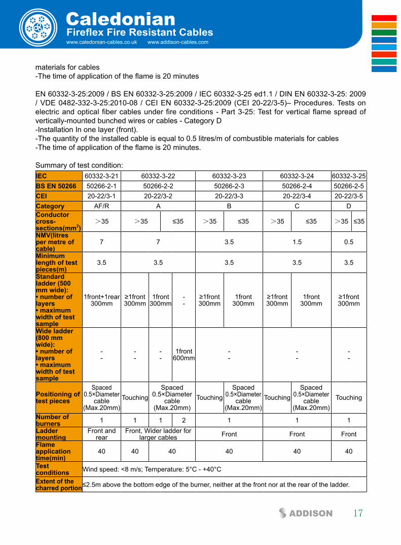
Summary of test condition:iec 60332-3-21 60332-3-22 60332-3-23 60332-3-24 60332-3-25bs en 50266 50266-2-1 50266-2-2 50266-2-3 50266-2-4 50266-2-5cei 20-22/3-1 20-22/3-2 20-22/3-3 20-22/3-4 20-22/3-5category AF/R A B C Dconductor cross-sections(mm2)
>35 >35 ≤35 >35 ≤35 >35 ≤35 >35 ≤35
nMV(iitres per metre of cable)
7 7 3.5 1.5 0.5
Minimum length of test pieces(m)
3.5 3.5 3.5 3.5 3.5
standard ladder (500 mm wide):• number of layers• maximum width of test sampie
1front+1rear300mm
≥1front300mm
1front300mm
--
≥1front300mm
1front300mm
≥1front300mm
1front300mm
≥1front300mm
Wide ladder (800 mm wide):• number of layers• maximum width of test sampie
--
--
--
1front600mm
--
--
--
Positioning of test pieces
Spaced 0.5×Diameter
cable(Max.20mm)
TouchingSpaced
0.5×Diameter cable
(Max.20mm)Touching
Spaced 0.5×Diameter
cable(Max.20mm)
TouchingSpaced
0.5×Diameter cable
(Max.20mm)Touching
number of burners 1 1 1 2 1 1 1ladder mounting
Front and rear
Front, Wider ladder forlarger cables Front Front Front
flame application time(min)
40 40 40 40 40 40
Testconditions Wind speed: <8 m/s; Ternperature: 5°C - +40°C
Extent of the charred portion≤2.5m above the bottom edge of the burner, neither at the front nor at the rear of the ladder.
ADDISON
Caledonian18
Reduced fire propagation in accordance with NF C32-070-2.2(C1)NF C32-070 :2001 Insulated conductors and cables for installation.-Classification tests on conductors and cables with regard to fire behavior.
A 1600mm vertically installed bundled of cable is exposed to the effects of a radiating oven (approx 830°C) and forced ventilation. Pilot flames arranged above the oven burn off the emitted gases. The test duration is 30 minutes, with the ventilation stopped for every 10 minutes during the flame application period. The cable sample is classified under Category C1 according to NF F 32070-2.2 if the carbonised part of the cable sample does not extend more than 0.8m above the upper base of the oven.
Depending on the damaged length, they can be further classified into 4 classes A, B, C and D according to NF F 16-101 as follows:category Test ResultA No damaged length from top of the oven in upper position.B Damaged length from top of oven in upper position not extending more than 50mm.C Damaged length from top of oven in upper position not extending more than 300mm
D Damaged length from top of oven in upper position not extending above the top of the chimney
Reduced fire Propagation in accordance to en 50266-1, en 50266-2-2, en 50266-2-3, en 50266-2-4. EN 50266-1:2001 / BS EN 50266-1:2001 / DIN EN 50266-1:2001 / VDE 0482-266-1:2001-09– Common test methods for cables under fire conditions. Test for vertical flame spread of vertically mounted bunched wires or cables - Part 1: Apparatus (Replaced by EN 60332-3-10:2009)
EN 50266-2-1:2001 / BS EN 50266-2-1:2001 / DIN EN 50266-2-1:2001 / VDE 0482-266-2-1:2001-09 / CEI EN 50266-2-1– Common test methods for cables under fire conditions. Test for vertical flame spread of vertically mounted bunched wires or cables - Part 2-1 : Procedures. Category A F/R (Replaced by EN 60332-3-21:2009)
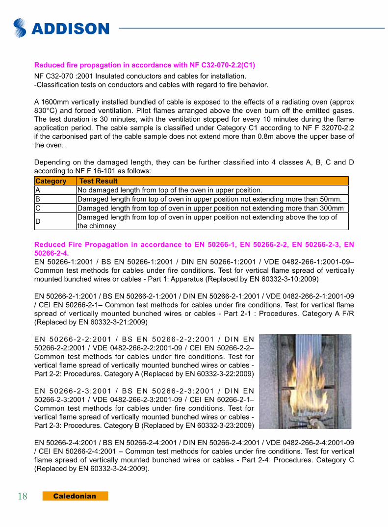
EN 50266-2-2 :2001 / BS EN 50266-2-2 :2001 / D IN EN 50266-2-2:2001 / VDE 0482-266-2-2:2001-09 / CEI EN 50266-2-2– Common test methods for cables under fire conditions. Test for vertical flame spread of vertically mounted bunched wires or cables - Part 2-2: Procedures. Category A (Replaced by EN 60332-3-22:2009)
EN 50266-2-3 :2001 / BS EN 50266-2-3 :2001 / D IN EN 50266-2-3:2001 / VDE 0482-266-2-3:2001-09 / CEI EN 50266-2-1– Common test methods for cables under fire conditions. Test for vertical flame spread of vertically mounted bunched wires or cables - Part 2-3: Procedures. Category B (Replaced by EN 60332-3-23:2009)
EN 50266-2-4:2001 / BS EN 50266-2-4:2001 / DIN EN 50266-2-4:2001 / VDE 0482-266-2-4:2001-09 / CEI EN 50266-2-4:2001 – Common test methods for cables under fire conditions. Test for vertical flame spread of vertically mounted bunched wires or cables - Part 2-4: Procedures. Category C (Replaced by EN 60332-3-24:2009).
www.caledonian-cables.co.uk www.addison-cables.com
Caledonian
19ADDISON
Fireflex Fire Resistant Cables
Reduced fire Propagation in accordance with bs 4066-3BS 4066-3:1994 (superseded) – Tests on electic cables under fire conditions. Tests on bunched wires or cables. This standard is no longer in force and is replaced by the BS EN 50266-1:2001
Reduced fire Propagation in accordance with nbn c 32-004 (f2)NBN C 32-004 specifies a method of test for measuring the vertical flame propagation characteristics of a bunch of cables. The cable specimen is deemed to have passed the test and categorized as F2 if after burning has ceased, the extent of charred or affected portion does not reach a height exceeding 2.5m above the bottom edge of the burner.
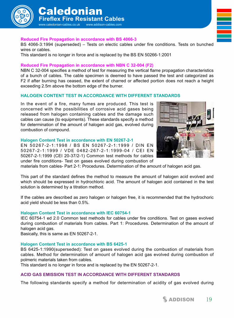
HalOGen cOnTenT TesT in accORDance WiTH DiffeRenT sTanDaRDs
In the event of a fire, many fumes are produced. This test is concerned with the possibilities of corrosive acid gases being released from halogen containing cables and the damage such cables can cause (to equipments). These standards specify a method for determination of the amount of halogen acid gas, evolved during combustion of compound.
Halogen content Test in accordance with en 50267-2-1EN 50267-2-1 :1998 / BS EN 50267-2-1 :1999 / D IN EN 50267-2-1 :1999 / VDE 0482-267-2-1 :1999-04 / CEI EN 50267-2-1:1999 (CEI 20-37/2-1) Common test methods for cables under fire conditions- Test on gases evolved during combustion of materials from cables- Part 2-1: Procedures. Determination of the amount of halogen acid gas.
This part of the standard defines the method to measure the amount of halogen acid evolved and which should be expressed in hydrochloric acid. The amount of halogen acid contained in the test solution is determined by a titration method.
If the cables are described as zero halogen or halogen free, it is recommended that the hydrochoric acid yield should be less than 0.5%.
Halogen content Test in accordance with iec 60754-1IEC 60754-1 ed 2.0 Common test methods for cables under fire conditions. Test on gases evolved during combustion of materials from cables. Part 1: Procedures. Determination of the amount of halogen acid gas. Basically, this is same as EN 50267-2-1.
Halogen content Test in accordance with bs 6425-1BS 6425-1:1990(superseded): Test on gases evolved during the combustion of materials from cables. Method for determination of amount of halogen acid gas evolved during combustion of polmeric materials taken from cables. This standard is no longer in force and is replaced by the EN 50267-2-1.
aciD Gas eMissiOn TesT in accORDance WiTH DiffeRenT sTanDaRDs
The following standards specify a method for determination of acidity of gas evolved during

ADDISON
Caledonian20
combustion of cables by measuring PH and conductivity. This test allows to determine the corrosivity of the acid gases generally halogens, that develop during the electric cable combustion.
acid Gas emission Test in accordance with en 50267-2-2EN 50267-2-2:1999 / BS EN 50267-2-2:1999 / DIN EN 50267-2-2:1999 / VDE 0482-267-2-2:1999-04 / CEI EN 50267-2-2:1999 (CEI 20-37/2-2). Common test methods for cables under fire conditions- Test on gases evolved during combustion of materials from cables- Part 2-2: Procedures. Determination of degree of acidity of gases for materials by measuring PH and conductivity. The standard states that the pH and the conductivity of a test solution should be measured, using calibrated PH and conductivity meters.
If the cables are described as zero halogen or halogen free, it is recommended that at least both of the following requirements should be met for each of the individual materials of a cable:
-The PH value should not be less than 4.3 when related to 1 litre of water -The conductivity should not be less than 10us/mm when related to 1 litre of water
EN 50267-2-3:1999 / BS EN 50267-2-3:1999 / DIN EN 50267-2-3:1999 / VDE 0482-267-2-3:1999-04 / CEI EN 50267-2-3:1999 (CEI 20-37/2-3). Common test methods for cables under fire conditions- Test on gases evolved during combustion of materials from cables- Part 2-3:Procedures. Determination of degree of acidity of gases for cables by determination of the weighted average of pH and conductivity.
The standard states that the pH and the conductivity of a test solution should be measured, using calibrated pH and conductivity meters. The results from the different components of the cable are then weighted.
acid Gas emission Test in accordance with iec 60754-2IEC 60754-2 ed1.0 Test on gases evolved during combustion of electric cables - Part 2 : Determination of degree of acidity of gases evolved during combustion of materials taken from electric cables by measuring pH and conductivity.
acid Gas emission Test in accordance with nf c32-074NF C32-074 Common test methods for cables under fire conditions - Test on gases evolved during combustion of materials from cables. This standard is equivalent to IEC 60754-2
acid Gas emission Test in accordance with bs 6425-2BS 6425-2:1993 (superseded) Test on gases evolved during the combusion of materials from cables. Determination of degree of acidity (corrosivity) of gases by measuring pH and conductivity.
This standard is no longer in force and is replaced by the EN 50267-2-2:1999.
acid Gas emission Test in accordance with Din VDe 0472-813 / VDe 0472-813:1994 DIN VDE 0472-813 / VDE 0472-813:1994 Corrosivity of combustion gases.

www.caledonian-cables.co.uk www.addison-cables.com
Caledonian
21ADDISON
Fireflex Fire Resistant Cables
The standards are no longer in force and are replaced by the EN 50267-2-2 & VDE 0482-267-2-2.
sMOKe DensiTy TesT in accORDance WiTH DiffeRenT sTanDaRDs
The smoke density measurement taken from a material under fire conditions gives an indication of the visibility through the smoke. This is important as reduced visibility in a real fire situation makes it more difficult to escape from the fire thus increasing the threat to human life from the toxic gas, fumes and heat. The following standards specify the method for measuring the generation of smoke from cables during fire.
smoke Density Test in accordance with iec 61034-1 & iec 61034-2IEC 61034-1:2005 / EN 61034-1:2005 / BS EN 61034-1:2005 / DIN EN 61034-1:2006 / VDE 0482-1034-1:2006 Measurement of smoke density of cables burning under defined conditions. Part 1: Test apparatus
IEC 61034-2:2005 / EN 61034-2:2005 / BS EN 61034-2:2005 / DIN EN 61034-2:2006 / VDE 0482-1034-2:2006 / CEI EN 61034-2:2006 (CEI 20-37/3-1) Measurement of smoke density of cables burning under defined conditions. Part 2: Test procedure and requirements.
The standard specifies a method of measurement of smoke density of cables. Part 1 specifies the test apparatus and Part 2 specifies the test procedure.
The test is usually performed inside a chamber of 3m x3m x3m and the test is sometimes described as 3 metre cube test. The test is performed by monitoring the tranmittance reduction of a white light beam, running from one side of the chamber to the other, at a set height, thus monitoring the build up of smoke inside the chamber. The minimum percentage of light transmittance is often used to determine if the cable has passed or failed the test , often a minimum light transmittance of 60% is applied in order to classify a cable as low smoke.
smoke Density Test in accordance with nf c32- 073NF C32 073 Common test methods for cables under fire conditions. - Measurement of smoke density of cables burning under defined conditions. This standard is equivalent to IEC 61034-2
smoke Density Test in accordance with bs 7622-1 & bs 7622-2BS 7622-1:1993 (superseded) – Measurement of smoke density of electric cables burning under defined condiitions. Test apparatus. BS 7622-2:1993 (superseded) – Measurement of smoke density of electric cables burning under defined condiitions. Test procedure and requirements.
The standards are no longer in force and were replaced by the EN 50268-1:2000 and EN 50268-2:2000 even though they too were superseded by EN 61034-1:2005 and EN 61034-2:2005.

ADDISON
Caledonian22
smoke Density Test in accordance with en 50268-1 & en 50268-2EN 50268-1:2000 / BS EN 50268-1:2000 / DIN EN 50268-1:2000 / VDE 0482-268-1:2000 (superseded) – Common test methods for cables under fire conditions. Measurement of smoke density of cable burning under defined conditions. Part 1: ApparatusEN 50268-2:2000 / BS EN 50268-2:2000 / DIN EN 50268-2:2000 / VDE 0482-268-2:2000 (superseded) – Common test methods for cables under fire conditions. Measurement of smoke density of cable burning under defined conditions. Part 2: Procedure.The standards are no longer in force and are replaced by the EN 61034-1:2005 and EN 61034-2:2005. Although these standards have been withdrawn, they are still called upon in some specification documents such as in the London Underground specification 1-085.
smoke Density Test in accordance with Din VDe 0472-816 / VDe 0472-816:1994DIN VDE 0472-816/VDE 0472-816:1994 Testing of cables, wires and flexible cords. Smoke Density.
The standards are no longer in force and are replaced by the EN 50268-1, VDE 0482-268-1, EN 50268-2 & VDE 0482-268-2 which are also replaced by the EN 61034-1:2005 and EN 61034-2:2005.
OxyGen inDex TesT in accORDance WiTH DiffeRenT sTanDaRDs
The oxygen index is defined as the minimum concentration of oxygen, expressed as volume percentage, in a mixture of oxygen and nitrogen that will just support combustion of a material initially at room temperature under specified test conditions.
Oxygen Index Test in accordance with ASTM D 2863ASTM D 2863-10 Measuring the minimum oxygen concentration to support candle-like combustion of plastics (Oxygen Index).
The test is performed in accordance with the procedure specified in ASTM 2863-95 using test piece cut from the outer sheath of the cable. The apparatus holds a small specimen which is clamped vertically in a tube in an atmosphere where the relative concentration of oxygen and nitrogen can be changed. The aim is to test the flammability of the sample with a small pilot flame to find the minimum oxygen concentration required to just sustain combustion of the sample.
Oxygen Index Test in accordance with ISO 4589-2ISO4589-2:1996 Determination of burning behaviour by oxygen index Part 2: Ambient temperature test. Specimens measuring 100mm long by 6mm wide are used for testing. The test is performed in accordance with the procedure specified in the standard.
TeMPeRaTURe inDex TesT in accORDance WiTH DiffeRenT sTanDaRDs
This is a test for assessing the performance of a material when it is tested in accordance with BS2782: Part 1: Method 143a and 143b. The oxygen index of a material will drop when the temperature rises. When the temperature rises and the oxygen index drops to 21%, the material will burn

www.caledonian-cables.co.uk www.addison-cables.com
Caledonian
23ADDISON
Fireflex Fire Resistant Cables
automatically. This temperature is defined as temperature index. For example, the oxygen index of the coal at room temperature is 50% and when the temperature climbs to 150°C, it’s oxygen index drops to 21°C and the coal will burn by itself automatically. The temperature index of the coal is defined as 150°C. In general, the temperature index of fire retardant cable exceeds 250°C.
Temperature Index Test in accordance with BS 2782BS 2782: Part 1:1989 Method 143a and 143b Temperature of materials. Determination of flammability.Specimens measuring nominally 100mm long by 6.5mm wide by 3mm thick are used for testing. The specimens are then tested in accordance with the test procedure specified in the standard.
Temperature Index Test in accordance with ISO 4589-3ISO4589-3:1996 Determination of burning behaviour by oxygen index Part 3: Elevated temperature test.Specimens measuring 100mm long by 6mm wide are used for testing. The test is performed in accordance with the procedure specified in the standard.
TOxiciTy TesT in accORDance WiTH different standards
Toxicity test in accordance with NES 02-713Measuring a fume from a material exposed to a controlled fire conditions gives an indication of the fumes which may be produced in a real fire situation. A standard method of test for determining the toxicity of materials under fire condition is Defense Standard NES 02-713- Toxicity. This method gives the level of toxicity of the fumes produced from the material under test. During the test, the test specimen is heated via direct flame application at 1150°C.
The flame is applied via a bunsen burner with a flame height of between 100m and 125mm formed with a methane gas and an external supply of compressed air. The specimen toxicity is determined from accurate pre-analysis weight (4pp) colorimetric tubes and ion chromatography.
The test may determine the following species: Hydrogen Bromide, Hydrochloric Acid, Hydrogen Fluoride, Formaldehyde, Nitrous gases, Carbon Monoxide, Carbon Dioxide, Acrylonitrile, Phenol, Hydrogen Sulphide, Sulphur Dioxide, Hydrocyanic Acid, Ammonia. The concentration in ppm for each gas detected are provided. The toxicity index of the speciments summates the toxic gases, taking into account of their level of danger to humans. The smaller the toxicity index, the better the product. A limit of 5 is often applicable.
Toxicity test in accordance with NF C 20-454NF C 20-454 base environmental testing procedures. Fire behaviour. Analysis and titration of gases evolved during pyrolysis or combustion of materials used in electrotechnics. Exposure to abnormal heat or fire. Tube furnace method.
The test defined by this standard serves to define the conventional toxicity index (cti) of the gases emitted by the insulating or sleeving materials during combustion at 800°C.

ADDISON
Caledonian24
Toxicity test in accordance with NF X 70-100NF X 70-100 Fire Tests; Analysis of gaseous effluents.
The test is conducted within a tube furnace where the temperature is set at either 400°C, 600°C, 800°C (commonly 600°C is used for most of the materials or 800°C for some electrical products) for 40 minutes throughout the test by analysis of the toxicity index of the gases including CO, CO2, HCL, HBr, HCN, HF and SO2.
www.caledonian-cables.co.uk www.addison-cables.com
Caledonian
25ADDISON
fire Resistant Power & control cables
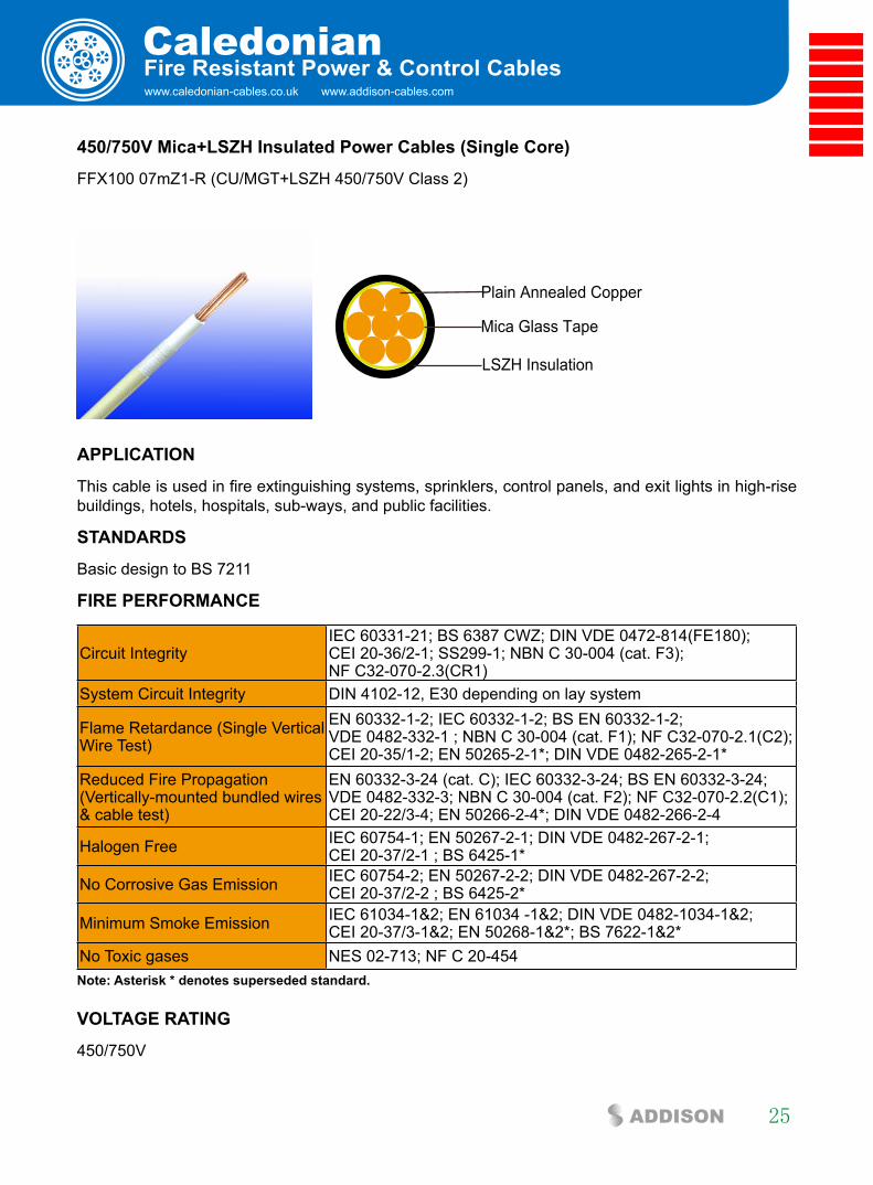
450/750V Mica+lsZH insulated Power cables (single core)
FFX100 07mZ1-R (CU/MGT+LSZH 450/750V Class 2)
Mica Glass Tape
Plain Annealed Copper
LSZH Insulation
aPPlicaTiOn
This cable is used in fire extinguishing systems, sprinklers, control panels, and exit lights in high-rise buildings, hotels, hospitals, sub-ways, and public facilities.
sTanDaRDs
Basic design to BS 7211
fiRe PeRfORMance
Circuit IntegrityIEC 60331-21; BS 6387 CWZ; DIN VDE 0472-814(FE180); CEI 20-36/2-1; SS299-1; NBN C 30-004 (cat. F3); NF C32-070-2.3(CR1)
System Circuit Integrity DIN 4102-12, E30 depending on lay system
Flame Retardance (Single Vertical Wire Test)
EN 60332-1-2; IEC 60332-1-2; BS EN 60332-1-2; VDE 0482-332-1 ; NBN C 30-004 (cat. F1); NF C32-070-2.1(C2); CEI 20-35/1-2; EN 50265-2-1*; DIN VDE 0482-265-2-1*
Reduced Fire Propagation (Vertically-mounted bundled wires & cable test)
EN 60332-3-24 (cat. C); IEC 60332-3-24; BS EN 60332-3-24; VDE 0482-332-3; NBN C 30-004 (cat. F2); NF C32-070-2.2(C1); CEI 20-22/3-4; EN 50266-2-4*; DIN VDE 0482-266-2-4
Halogen Free IEC 60754-1; EN 50267-2-1; DIN VDE 0482-267-2-1; CEI 20-37/2-1 ; BS 6425-1*
No Corrosive Gas Emission IEC 60754-2; EN 50267-2-2; DIN VDE 0482-267-2-2; CEI 20-37/2-2 ; BS 6425-2*
Minimum Smoke Emission IEC 61034-1&2; EN 61034 -1&2; DIN VDE 0482-1034-1&2; CEI 20-37/3-1&2; EN 50268-1&2*; BS 7622-1&2*
No Toxic gases NES 02-713; NF C 20-454note: asterisk * denotes superseded standard.
VOlTaGe RaTinG
450/750V
ADDISON
Caledonian26
cable cOnsTRUcTiOn conductor: Plain annealed copper wire, stranded according to IEC 60228 class 2 fire barrier: Mica glass tapeinsulation: Thermoplastic LSZH compound type LTS3 as per BS 7655-6.1 (Thermosetting LSZH compound type SW2-SW4 as per BS 7655-2.6 can be offered.). UV resistance, hydrocarbon resistance, oil resistance, anti rodent and anti termite properties can be offered as option.
cOlOUR cODe
insulation colour as per bs7671
With Earth Conductor Without Earth Conductor
2Cores - Brown, Blue
3Cores Yellow/Green, Brown, Blue Brown, Gray, Black
4Cores Yellow/Green, Brown, Gray, Black Brown, Gray, Black, Blue5Cores Yellow/Green, Brown, Gray, Black, Blue Brown, Gray, Black, Blue, Blackabove 5 Cores Yellow/Green, Black Numbered Black Numberedsheath colour: Black (other colors upon request)
PHysical anD THeRMal PROPeRTies
Temperature range during operation (fixed state): -30°C – +90°C Temperature range during installation (mobile state): -20°C – +50°C Minimum bending radius: 6 x Overall Diameter
elecTRical PROPeRTies
Dielectric test: 450/750V: 2500 V r.m.s. x 5’ (core/core)
Insulation resistance 20 MΩ x km (at 20°C)Short circuit temperature 250°C
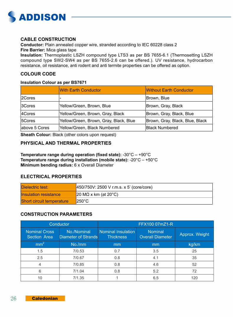
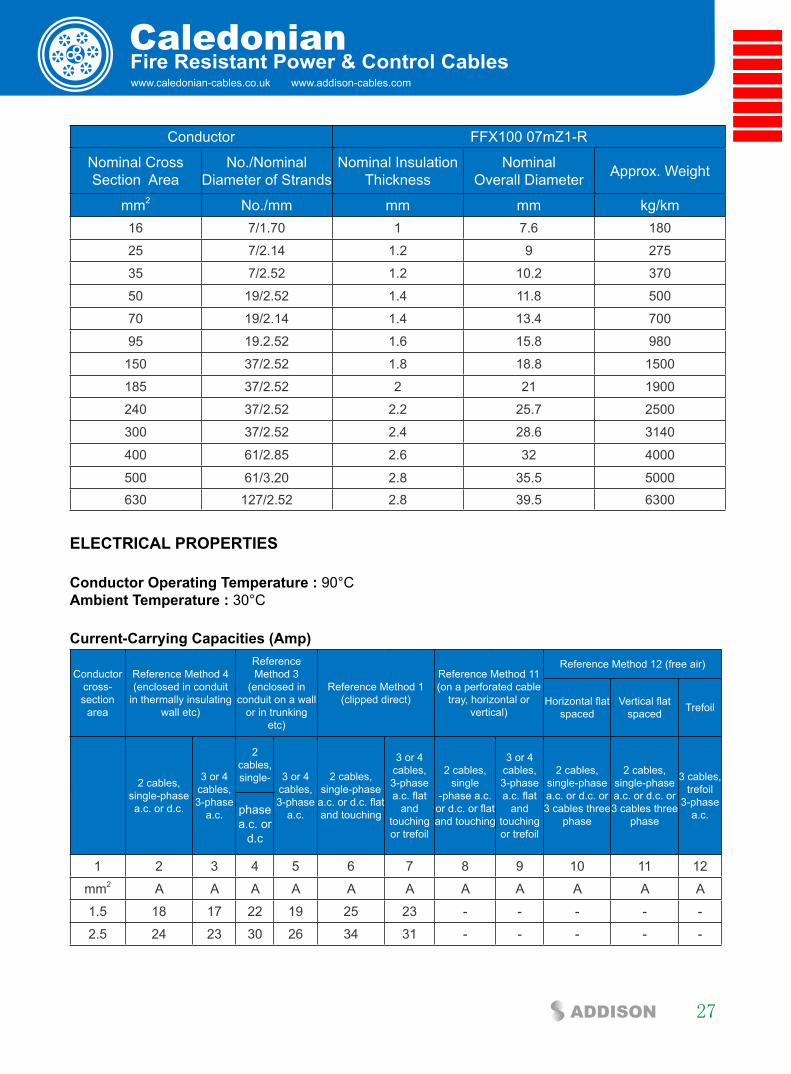
cOnsTRUcTiOn PaRaMeTeRs
Conductor FFX100 07mZ1-R
Nominal CrossSection Area
No./Nominal Diameter of Strands
Nominal Insulation Thickness
Nominal Overall Diameter Approx. Weight
mm2 No./mm mm mm kg/km1.5 7/0.53 0.7 3.5 25
2.5 7/0.67 0.8 4.1 35
4 7/0.85 0.8 4.6 52
6 7/1.04 0.8 5.2 72
10 7/1.35 1 6.5 120
www.caledonian-cables.co.uk www.addison-cables.com
Caledonian
27ADDISON
fire Resistant Power & control cables
Conductor FFX100 07mZ1-R
Nominal CrossSection Area
No./Nominal Diameter of Strands
Nominal Insulation Thickness
Nominal Overall Diameter Approx. Weight
mm2 No./mm mm mm kg/km16 7/1.70 1 7.6 180
25 7/2.14 1.2 9 275
35 7/2.52 1.2 10.2 370
50 19/2.52 1.4 11.8 500
70 19/2.14 1.4 13.4 700
95 19.2.52 1.6 15.8 980
150 37/2.52 1.8 18.8 1500
185 37/2.52 2 21 1900
240 37/2.52 2.2 25.7 2500
300 37/2.52 2.4 28.6 3140
400 61/2.85 2.6 32 4000
500 61/3.20 2.8 35.5 5000630 127/2.52 2.8 39.5 6300
elecTRical PROPeRTies
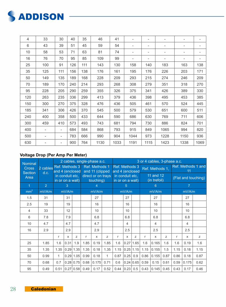
conductor Operating Temperature : 90°C ambient Temperature : 30°C
current-carrying capacities (amp)
Conductor cross-section
area
Reference Method 4 (enclosed in conduit
in thermally insulating wall etc)
Reference Method 3
(enclosed in conduit on a wall
or in trunking etc)
Reference Method 1 (clipped direct)
Reference Method 11 (on a perforated cable
tray, horizontal or vertical)
Reference Method 12 (free air)
Horizontal flat spaced
Vertical flat spaced Trefoil
2 cables, single-phase a.c. or d.c.
3 or 4 cables, 3-phase
a.c.
2 cables, single- 3 or 4
cables, 3-phase
a.c.
2 cables, single-phase
a.c. or d.c. flat and touching
3 or 4 cables, 3-phase a.c. flat
and touching or trefoil
2 cables, single
-phase a.c. or d.c. or flat and touching
3 or 4 cables, 3-phase a.c. flat
and touching or trefoil
2 cables, single-phase a.c. or d.c. or 3 cables three
phase
2 cables, single-phase a.c. or d.c. or 3 cables three
phase
3 cables, trefoil
3-phase a.c.phase
a.c. or d.c
1 2 3 4 5 6 7 8 9 10 11 12
mm2 A A A A A A A A A A A
1.5 18 17 22 19 25 23 - - - - -
2.5 24 23 30 26 34 31 - - - - -
ADDISON
Caledonian28
4 33 30 40 35 46 41 - - - - -
6 43 39 51 45 59 54 - - - - -
10 58 53 71 63 81 74 - - - - -
16 76 70 95 85 109 99 - - - - -
25 100 91 126 111 143 130 158 140 183 163 138
35 125 111 156 138 176 161 195 176 226 203 171
50 149 135 189 168 228 209 293 215 274 246 209
70 189 170 240 214 293 268 308 279 351 318 270
95 228 205 290 259 355 326 375 341 426 389 330
120 263 235 336 299 413 379 436 398 495 453 385
150 300 270 375 328 476 436 505 461 570 524 445
185 341 306 426 370 545 500 579 530 651 600 511
240 400 358 500 433 644 590 686 630 769 711 606
300 459 410 573 493 743 681 794 730 886 824 701
400 - - 684 584 868 793 915 849 1065 994 820
500 - - 783 666 990 904 1044 973 1228 1150 936
630 - - 900 764 1130 1033 1191 1115 1423 1338 1069
Voltage Drop (Per amp Per Meter)
Nominal Cross
Section Area
2 cables d.c.
2 cables, single-phase a.c. 3 or 4 cables, 3-phase a.c.Ref. Methods 3 and 4 (enclosed in conduit etc, in or on a wall)
Ref. Methods 1 and 11 (clipped
direct or on trays touching)
Ref. Methods 3 and 4 (enclosed in conduit etc, in or on a wall)
Ref. Methods 1, Ref. Methods 1 and 11
11 and 12 (in trefoil) (Flat and touching)
1 2 3 4 5 6 7
mm2 mV/A/m mV/A/m mV/A/m mV/A/m mV/A/m mV/A/m
1.5 31 31 27 27 27 27
2.5 19 19 16 16 16 16
4 33 12 10 10 10 10
6 7.8 7.9 6.8 6.8 6.8 6.8
10 4.7 4.7 4.7 4 4 4
16 2.9 2.9 2.9 2.5 2.5 2.5
r x z r x z r x z r x z r x z
25 1.85 1.6 0.31 1.9 1.85 0.19 1.85 1.6 0.27 1.65 1.6 0.165 1.6 1.6 0.19 1.6
35 1.35 1.35 0.29 1.35 1.35 0.18 1.35 1.15 0.25 1.15 1.15 0.155 1.5 1.15 0.18 1.15
50 0.99 1 0.29 1.05 0.99 0.18 1 0.87 0.25 0.9 0.86 0.155 0.87 0.86 0.18 0.87
70 0.68 0.7 0.28 0.75 0.68 0.175 0.71 0.6 0.24 0.65 0.59 0.15 0.61 0.59 0.175 0.62
95 0.49 0.51 0.27 0.58 0.49 0.17 0.52 0.44 0.23 0.5 0.43 0.145 0.45 0.43 0.17 0.46
www.caledonian-cables.co.uk www.addison-cables.com
Caledonian
29ADDISON
fire Resistant Power & control cables
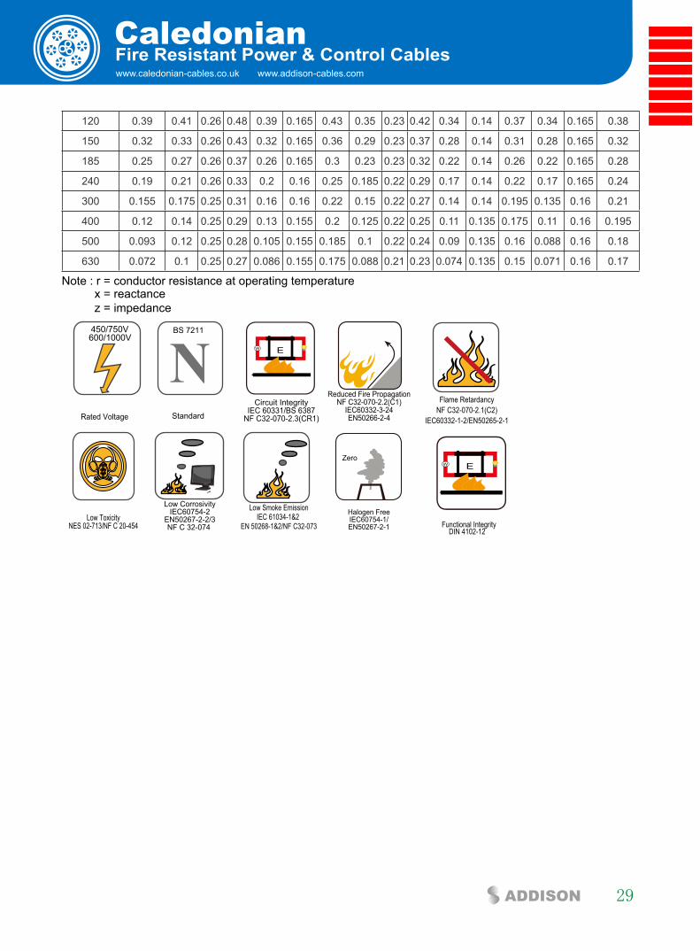
120 0.39 0.41 0.26 0.48 0.39 0.165 0.43 0.35 0.23 0.42 0.34 0.14 0.37 0.34 0.165 0.38
150 0.32 0.33 0.26 0.43 0.32 0.165 0.36 0.29 0.23 0.37 0.28 0.14 0.31 0.28 0.165 0.32
185 0.25 0.27 0.26 0.37 0.26 0.165 0.3 0.23 0.23 0.32 0.22 0.14 0.26 0.22 0.165 0.28
240 0.19 0.21 0.26 0.33 0.2 0.16 0.25 0.185 0.22 0.29 0.17 0.14 0.22 0.17 0.165 0.24
300 0.155 0.175 0.25 0.31 0.16 0.16 0.22 0.15 0.22 0.27 0.14 0.14 0.195 0.135 0.16 0.21
400 0.12 0.14 0.25 0.29 0.13 0.155 0.2 0.125 0.22 0.25 0.11 0.135 0.175 0.11 0.16 0.195
500 0.093 0.12 0.25 0.28 0.105 0.155 0.185 0.1 0.22 0.24 0.09 0.135 0.16 0.088 0.16 0.18
630 0.072 0.1 0.25 0.27 0.086 0.155 0.175 0.088 0.21 0.23 0.074 0.135 0.15 0.071 0.16 0.17
Note : r = conductor resistance at operating temperature x = reactance z = impedance
Rated Voltage
450/750V600/1000V
NStandard
BS 7211
Circuit IntegrityIEC 60331/BS 6387
NF C32-070-2.3(CR1)
W E
Reduced Fire PropagationNF C32-070-2.2(C1)
IEC60332-3-24EN50266-2-4
Flame RetardancyNF C32-070-2.1(C2)
IEC60332-1-2/EN50265-2-1
Low ToxicityNES 02-713/NF C 20-454
Low CorrosivityIEC60754-2
EN50267-2-2/3NF C 32-074
Low Smoke EmissionIEC 61034-1&2
EN 50268-1&2/NF C32-073
Zero
Halogen FreeIEC60754-1/EN50267-2-1
W E
DIN 4102-12Functional Integrity

ADDISON
Caledonian30
600/1000V Mica+lsZH insulated Power cables (single core)
FFX100 1mZ1-R (CU/MGT+LSZH 600/1000V Class 2)
Mica Glass Tape
Plain Annealed Copper
LSZH Insulation
aPPlicaTiOn
This cable is used in fire extinguishing systems, sprinklers, control panels, and exit lights in high-rise buildings, hotels, hospitals, sub-ways, and public facilities.
sTanDaRDs
Basic design to BS 7211
fiRe PeRfORMance
Circuit IntegrityIEC 60331-21; BS 6387 CWZ; DIN VDE 0472-814(FE180); CEI 20-36/2-1; SS299-1; NBN C 30-004 (cat. F3); NF C32-070-2.3(CR1)
System Circuit Integrity DIN 4102-12, E30 depending on lay system
Flame Retardance (Single Vertical Wire Test)
EN 60332-1-2; IEC 60332-1-2; BS EN 60332-1-2; VDE 0482-332-1 ; NBN C 30-004 (cat. F1); NF C32-070-2.1(C2); CEI 20-35/1-2; EN 50265-2-1*; DIN VDE 0482-265-2-1*
Reduced Fire Propagation (Vertically-mounted bundled wires & cable test)
EN 60332-3-24 (cat. C); IEC 60332-3-24; BS EN 60332-3-24; VDE 0482-332-3; NBN C 30-004 (cat. F2); NF C32-070-2.2(C1); CEI 20-22/3-4; EN 50266-2-4*; DIN VDE 0482-266-2-4
Halogen Free IEC 60754-1; EN 50267-2-1; DIN VDE 0482-267-2-1; CEI 20-37/2-1 ; BS 6425-1*
No Corrosive Gas Emission IEC 60754-2; EN 50267-2-2; DIN VDE 0482-267-2-2; CEI 20-37/2-2 ; BS 6425-2*
Minimum Smoke Emission IEC 61034-1&2; EN 61034 -1&2; DIN VDE 0482-1034-1&2; CEI 20-37/3-1&2; EN 50268-1&2*; BS 7622-1&2*
No Toxic gases NES 02-713; NF C 20-454note: asterisk * denotes superseded standard.
VOlTaGe RaTinG
600/1000V

www.caledonian-cables.co.uk www.addison-cables.com
Caledonian
31ADDISON
fire Resistant Power & control cables
cable cOnsTRUcTiOn
conductor: Plain annealed copper wire, stranded according to IEC 60228 class 2 fire barrier: Mica glass tapeinsulation: Thermoplastic LSZH compound type LTS3 as per BS 7655-6.1 (Thermosetting LSZH compound type SW2-SW4 as per BS 7655-2.6 can be offered.). UV resistance, hydrocarbon resistance, oil resistance, anti rodent and anti termite properties can be offered as option.
cOlOUR cODe
insulation colour as per bs7671
With Earth Conductor Without Earth Conductor
2Cores - Brown, Blue
3Cores Yellow/Green, Brown, Blue Brown, Gray, Black
4Cores Yellow/Green, Brown, Gray, Black Brown, Gray, Black, Blue5Cores Yellow/Green, Brown, Gray, Black, Blue Brown, Gray, Black, Blue, Blackabove 5 Cores Yellow/Green, Black Numbered Black Numberedsheath colour: Black (other colors upon request)
PHysical anD THeRMal PROPeRTies
Temperature range during operation (fixed state): -30°C – +90°C Temperature range during installation (mobile state): -20°C – +50°C Minimum bending radius: 6 x Overall Diameter
elecTRical PROPeRTies
Dielectric test: 600/1000V: 3500 V r.m.s. x 5’ (core/core); Insulation resistance 20 MΩ x km (at 20°C)Short circuit temperature 250°C
cOnsTRUcTiOn PaRaMeTeRs
Conductor FFX100 1mZ1-R
Nominal CrossSection Area
No./Nominal Diameter of Strands
Nominal Insulation Thickness
Nominal Overall Diameter Approx. Weight
mm2 No./mm mm mm kg/km1.5 7/0.53 0.8 3.8 30
2.5 7/0.67 0.8 4.2 40
4 7/0.85 1 5.3 70
6 7/1.04 1 6 96
10 7/1.35 1 6.6 130

ADDISON
Caledonian32
Conductor FFX100 1mZ1-R
Nominal CrossSection Area
No./Nominal Diameter of Strands
Nominal Insulation Thickness
Nominal Overall Diameter Approx. Weight
mm2 No./mm mm mm kg/km16 7/1.70 1 7.7 200
25 7/2.14 1.2 9.1 290
35 7/2.52 1.2 10.3 390
50 19/2.52 1.4 11.9 520
70 19/2.14 1.4 13.5 730
95 19.2.52 1.6 15.9 990
150 37/2.52 1.8 18.9 1520
185 37/2.52 2 21.2 1900
240 37/2.52 2.2 25.8 2550
300 37/2.52 2.4 28.8 3150
400 61/2.85 2.6 32.2 4000
500 61/3.20 2.8 35.7 5000630 127/2.52 2.8 39.7 6360
elecTRical PROPeRTies
conductor Operating Temperature : 90°C ambient Temperature : 30°C
current-carrying capacities (amp)
Conductor cross-section
area
Reference Method 4 (enclosed in conduit
in thermally insulating wall etc)
Reference Method 3
(enclosed in conduit on a wall
or in trunking etc)
Reference Method 1 (clipped direct)
Reference Method 11 (on a perforated cable
tray, horizontal or vertical)
Reference Method 12 (free air)
Horizontal flat spaced
Vertical flat spaced Trefoil
2 cables, single-phase a.c. or d.c.
3 or 4 cables, 3-phase
a.c.
2 cables, single- 3 or 4
cables, 3-phase
a.c.
2 cables, single-phase
a.c. or d.c. flat and touching
3 or 4 cables, 3-phase a.c. flat
and touching or trefoil
2 cables, single
-phase a.c. or d.c. or flat and touching
3 or 4 cables, 3-phase a.c. flat
and touching or trefoil
2 cables, single-phase a.c. or d.c. or 3 cables three
phase
2 cables, single-phase a.c. or d.c. or 3 cables three
phase
3 cables, trefoil
3-phase a.c.phase
a.c. or d.c
1 2 3 4 5 6 7 8 9 10 11 12
mm2 A A A A A A A A A A A
1.5 18 17 22 19 25 23 - - - - -
2.5 24 23 30 26 34 31 - - - - -
4 33 30 40 35 46 41 - - - - -

www.caledonian-cables.co.uk www.addison-cables.com
Caledonian
33ADDISON
fire Resistant Power & control cables
6 43 39 51 45 59 54 - - - - -
10 58 53 71 63 81 74 - - - - -
16 76 70 95 85 109 99 - - - - -
25 100 91 126 111 143 130 158 140 183 163 138
35 125 111 156 138 176 161 195 176 226 203 171
50 149 135 189 168 228 209 293 215 274 246 209
70 189 170 240 214 293 268 308 279 351 318 270
95 228 205 290 259 355 326 375 341 426 389 330
120 263 235 336 299 413 379 436 398 495 453 385
150 300 270 375 328 476 436 505 461 570 524 445
185 341 306 426 370 545 500 579 530 651 600 511
240 400 358 500 433 644 590 686 630 769 711 606
300 459 410 573 493 743 681 794 730 886 824 701
400 - - 684 584 868 793 915 849 1065 994 820
500 - - 783 666 990 904 1044 973 1228 1150 936
630 - - 900 764 1130 1033 1191 1115 1423 1338 1069
Voltage Drop (Per amp Per Meter)
Nominal Cross
Section Area
2 cables d.c.
2 cables, single-phase a.c. 3 or 4 cables, 3-phase a.c.Ref. Methods 3 and 4 (enclosed in conduit etc, in or on a wall)
Ref. Methods 1 and 11 (clipped
direct or on trays touching)
Ref. Methods 3 and 4 (enclosed in conduit etc, in or on a wall)
Ref. Methods 1, Ref. Methods 1 and 11
11 and 12 (in trefoil) (Flat and touching)
1 2 3 4 5 6 7
mm2 mV/A/m mV/A/m mV/A/m mV/A/m mV/A/m mV/A/m
1.5 31 31 27 27 27 27
2.5 19 19 16 16 16 16
4 33 12 10 10 10 10
6 7.8 7.9 6.8 6.8 6.8 6.8
10 4.7 4.7 4.7 4 4 4
16 2.9 2.9 2.9 2.5 2.5 2.5
r x z r x z r x z r x z r x z
25 1.85 1.6 0.31 1.9 1.85 0.19 1.85 1.6 0.27 1.65 1.6 0.165 1.6 1.6 0.19 1.6
35 1.35 1.35 0.29 1.35 1.35 0.18 1.35 1.15 0.25 1.15 1.15 0.155 1.5 1.15 0.18 1.15
50 0.99 1 0.29 1.05 0.99 0.18 1 0.87 0.25 0.9 0.86 0.155 0.87 0.86 0.18 0.87
70 0.68 0.7 0.28 0.75 0.68 0.175 0.71 0.6 0.24 0.65 0.59 0.15 0.61 0.59 0.175 0.62
95 0.49 0.51 0.27 0.58 0.49 0.17 0.52 0.44 0.23 0.5 0.43 0.145 0.45 0.43 0.17 0.46
120 0.39 0.41 0.26 0.48 0.39 0.165 0.43 0.35 0.23 0.42 0.34 0.14 0.37 0.34 0.165 0.38
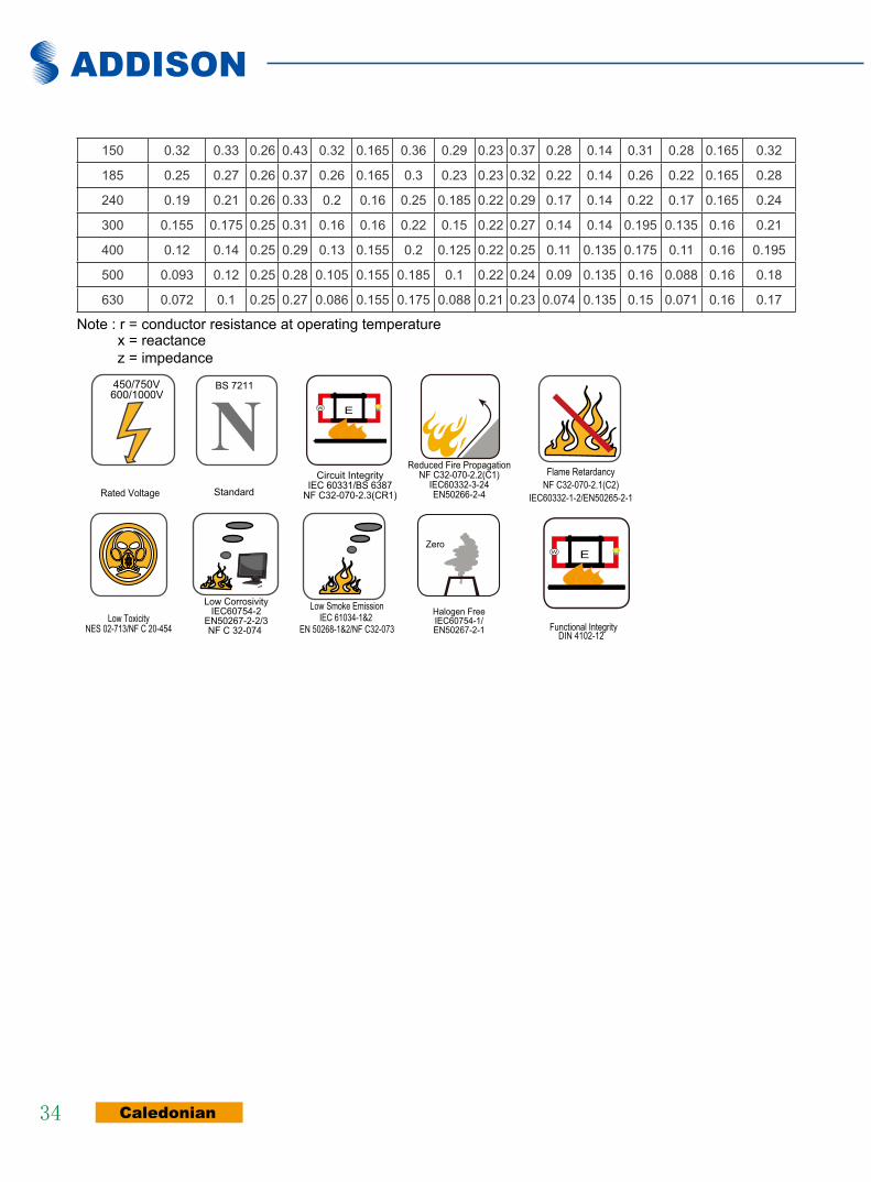
ADDISON
Caledonian34
150 0.32 0.33 0.26 0.43 0.32 0.165 0.36 0.29 0.23 0.37 0.28 0.14 0.31 0.28 0.165 0.32
185 0.25 0.27 0.26 0.37 0.26 0.165 0.3 0.23 0.23 0.32 0.22 0.14 0.26 0.22 0.165 0.28
240 0.19 0.21 0.26 0.33 0.2 0.16 0.25 0.185 0.22 0.29 0.17 0.14 0.22 0.17 0.165 0.24
300 0.155 0.175 0.25 0.31 0.16 0.16 0.22 0.15 0.22 0.27 0.14 0.14 0.195 0.135 0.16 0.21
400 0.12 0.14 0.25 0.29 0.13 0.155 0.2 0.125 0.22 0.25 0.11 0.135 0.175 0.11 0.16 0.195
500 0.093 0.12 0.25 0.28 0.105 0.155 0.185 0.1 0.22 0.24 0.09 0.135 0.16 0.088 0.16 0.18
630 0.072 0.1 0.25 0.27 0.086 0.155 0.175 0.088 0.21 0.23 0.074 0.135 0.15 0.071 0.16 0.17
Note : r = conductor resistance at operating temperature x = reactance z = impedance
Rated Voltage
450/750V600/1000V
NStandard
BS 7211
Circuit IntegrityIEC 60331/BS 6387
NF C32-070-2.3(CR1)
W E
Reduced Fire PropagationNF C32-070-2.2(C1)
IEC60332-3-24EN50266-2-4
Flame RetardancyNF C32-070-2.1(C2)
IEC60332-1-2/EN50265-2-1
Low ToxicityNES 02-713/NF C 20-454
Low CorrosivityIEC60754-2
EN50267-2-2/3NF C 32-074
Low Smoke EmissionIEC 61034-1&2
EN 50268-1&2/NF C32-073
Zero
Halogen FreeIEC60754-1/EN50267-2-1
W E
DIN 4102-12Functional Integrity

www.caledonian-cables.co.uk www.addison-cables.com
Caledonian
35ADDISON
fire Resistant Power & control cables
300/500V Mica+xlPe insulated, lsZH sheathed Power cables (single core)
FFX300 05mRZ1-R (CU/MGT+XLPE/LSZH 300/500V Class 2)
Mica Glass Tape
Plain Annealed Copper
XLPE Insulation
LSZH Outer Sheath
aPPlicaTiOn
The cables are designed for areas where the integrity of the electrical circuit is critical in maintaining power supply. Applications can be found in emergency lightings, control and power circuits, power stations, fire alarm systems, underground tunnels, lifts, escalators, and high-rise buildings.
sTanDaRDs
Basic design to IEC 60502-1
fiRe PeRfORMance
Circuit IntegrityIEC 60331-21; BS 6387 CWZ; DIN VDE 0472-814(FE180); CEI 20-36/2-1; SS299-1; NBN C 30-004 (cat. F3); NF C32-070-2.3(CR1)
System Circuit Integrity DIN 4102-12, E30 depending on lay system
Flame Retardance (Single Vertical Wire Test)
EN 60332-1-2; IEC 60332-1-2; BS EN 60332-1-2; VDE 0482-332-1 ; NBN C 30-004 (cat. F1); NF C32-070-2.1(C2); CEI 20-35/1-2; EN 50265-2-1*; DIN VDE 0482-265-2-1*
Reduced Fire Propagation (Vertically-mounted bundled wires & cable test)
EN 60332-3-24 (cat. C); IEC 60332-3-24; BS EN 60332-3-24; VDE 0482-332-3; NBN C 30-004 (cat. F2); NF C32-070-2.2(C1); CEI 20-22/3-4; EN 50266-2-4*; DIN VDE 0482-266-2-4
Halogen Free IEC 60754-1; EN 50267-2-1; DIN VDE 0482-267-2-1; CEI 20-37/2-1 ; BS 6425-1*
No Corrosive Gas Emission IEC 60754-2; EN 50267-2-2; DIN VDE 0482-267-2-2; CEI 20-37/2-2 ; BS 6425-2*
Minimum Smoke Emission IEC 61034-1&2; EN 61034 -1&2; DIN VDE 0482-1034-1&2; CEI 20-37/3-1&2; EN 50268-1&2*; BS 7622-1&2*
No Toxic gases NES 02-713; NF C 20-454note: asterisk * denotes superseded standard.
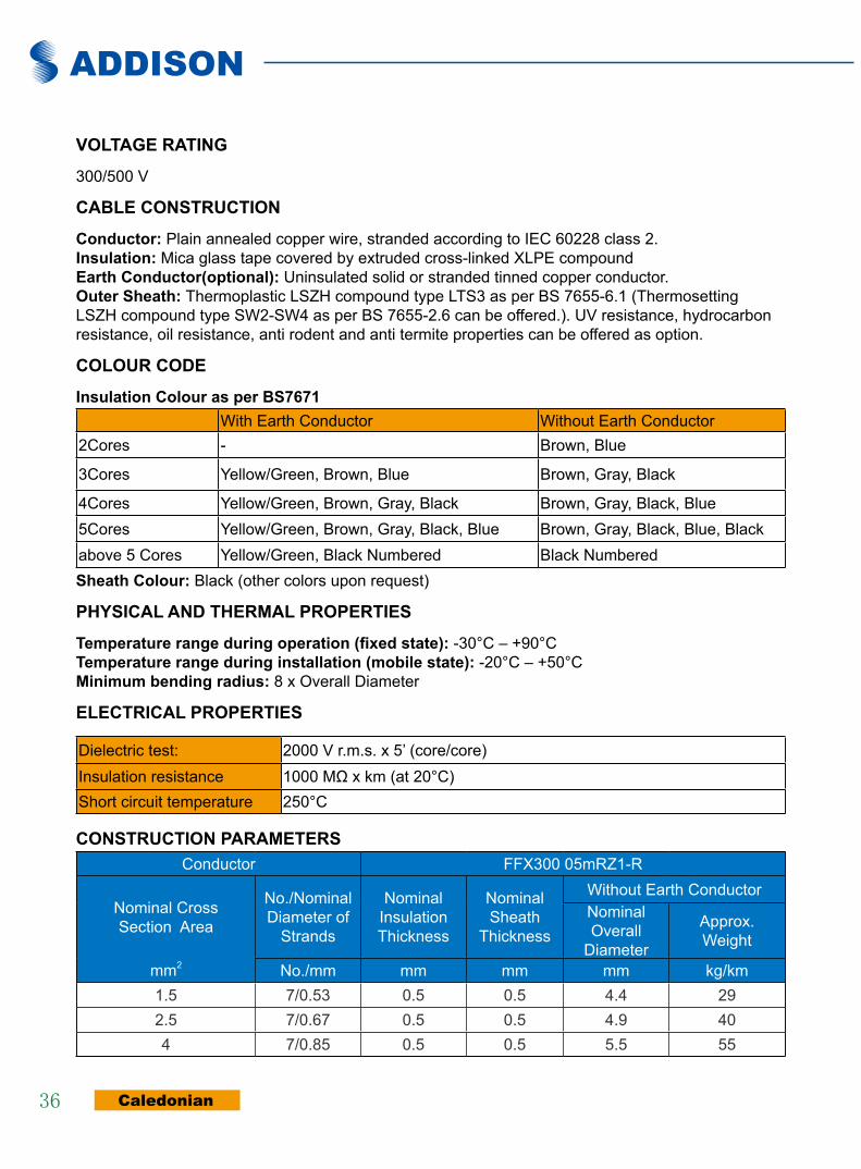
ADDISON
Caledonian36
VOlTaGe RaTinG
300/500 V
cable cOnsTRUcTiOn
conductor: Plain annealed copper wire, stranded according to IEC 60228 class 2.insulation: Mica glass tape covered by extruded cross-linked XLPE compoundearth conductor(optional): Uninsulated solid or stranded tinned copper conductor.Outer sheath: Thermoplastic LSZH compound type LTS3 as per BS 7655-6.1 (Thermosetting LSZH compound type SW2-SW4 as per BS 7655-2.6 can be offered.). UV resistance, hydrocarbon resistance, oil resistance, anti rodent and anti termite properties can be offered as option.
cOlOUR cODe
insulation colour as per bs7671With Earth Conductor Without Earth Conductor
2Cores - Brown, Blue
3Cores Yellow/Green, Brown, Blue Brown, Gray, Black
4Cores Yellow/Green, Brown, Gray, Black Brown, Gray, Black, Blue5Cores Yellow/Green, Brown, Gray, Black, Blue Brown, Gray, Black, Blue, Blackabove 5 Cores Yellow/Green, Black Numbered Black Numberedsheath colour: Black (other colors upon request)
PHysical anD THeRMal PROPeRTies
Temperature range during operation (fixed state): -30°C – +90°C Temperature range during installation (mobile state): -20°C – +50°C Minimum bending radius: 8 x Overall Diameter
elecTRical PROPeRTies
Dielectric test: 2000 V r.m.s. x 5’ (core/core)Insulation resistance 1000 MΩ x km (at 20°C)Short circuit temperature 250°C
cOnsTRUcTiOn PaRaMeTeRsConductor FFX300 05mRZ1-R
Nominal CrossSection Area
No./Nominal Diameter of
Strands
Nominal Insulation Thickness
Nominal Sheath
Thickness
Without Earth ConductorNominal Overall
Diameter
Approx. Weight
mm2 No./mm mm mm mm kg/km1.5 7/0.53 0.5 0.5 4.4 292.5 7/0.67 0.5 0.5 4.9 404 7/0.85 0.5 0.5 5.5 55
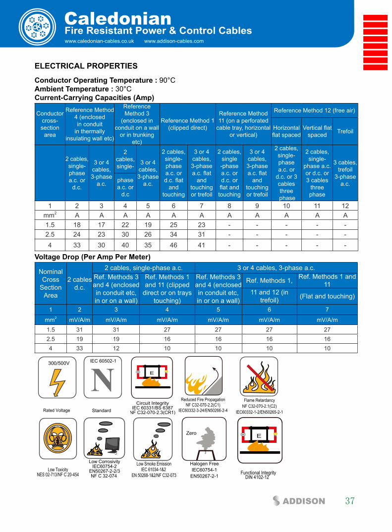
www.caledonian-cables.co.uk www.addison-cables.com
Caledonian
37ADDISON
fire Resistant Power & control cables
elecTRical PROPeRTies
conductor Operating Temperature : 90°C ambient Temperature : 30°C current-carrying capacities (amp)
Conductor cross-section
area
Reference Method 4 (enclosed in conduit
in thermally insulating wall etc)
Reference Method 3
(enclosed in conduit on a wall
or in trunking etc)
Reference Method 1 (clipped direct)
Reference Method 11 (on a perforated
cable tray, horizontal or vertical)
Reference Method 12 (free air)
Horizontal flat spaced
Vertical flat spaced Trefoil
2 cables, single-phase a.c. or
d.c.
3 or 4 cables, 3-phase
a.c.
2 cables, single- 3 or 4
cables, 3-phase
a.c.
2 cables, single-phase a.c. or d.c. flat
and touching
3 or 4 cables, 3-phase a.c. flat
and touching or trefoil
2 cables, single-phase a.c. or d.c. or flat and touching
3 or 4 cables, 3-phase a.c. flat
and touching or trefoil
2 cables, single-phase a.c. or
d.c. or 3 cables three
phase
2 cables, single-
phase a.c. or d.c. or 3 cables
three phase
3 cables, trefoil
3-phase a.c.phase
a.c. or d.c
1 2 3 4 5 6 7 8 9 10 11 12mm2 A A A A A A A A A A A1.5 18 17 22 19 25 23 - - - - -2.5 24 23 30 26 34 31 - - - - -4 33 30 40 35 46 41 - - - - -
Voltage Drop (Per amp Per Meter)
Nominal Cross
Section Area
2 cables d.c.
2 cables, single-phase a.c. 3 or 4 cables, 3-phase a.c.Ref. Methods 3 and 4 (enclosed in conduit etc, in or on a wall)
Ref. Methods 1 and 11 (clipped
direct or on trays touching)
Ref. Methods 3 and 4 (enclosed in conduit etc, in or on a wall)
Ref. Methods 1, Ref. Methods 1 and 11
11 and 12 (in trefoil) (Flat and touching)
1 2 3 4 5 6 7
mm2 mV/A/m mV/A/m mV/A/m mV/A/m mV/A/m mV/A/m1.5 31 31 27 27 27 272.5 19 19 16 16 16 164 33 12 10 10 10 10
Rated Voltage
300/500V
NStandard
IEC 60502-1
Circuit IntegrityIEC 60331/BS 6387
NF C32-070-2.3(CR1)
W E
Reduced Fire PropagationNF C32-070-2.2(C1)
IEC60332-3-24/EN50266-2-4
Flame RetardancyNF C32-070-2.1(C2)
IEC60332-1-2/EN50265-2-1
Low ToxicityNES 02-713/NF C 20-454
Low CorrosivityIEC60754-2
EN50267-2-2/3NF C 32-074
Low Smoke EmissionIEC 61034-1&2
EN 50268-1&2/NF C32-073
Zero
Halogen FreeIEC60754-1
EN50267-2-1
W E
DIN 4102-12Functional Integrity
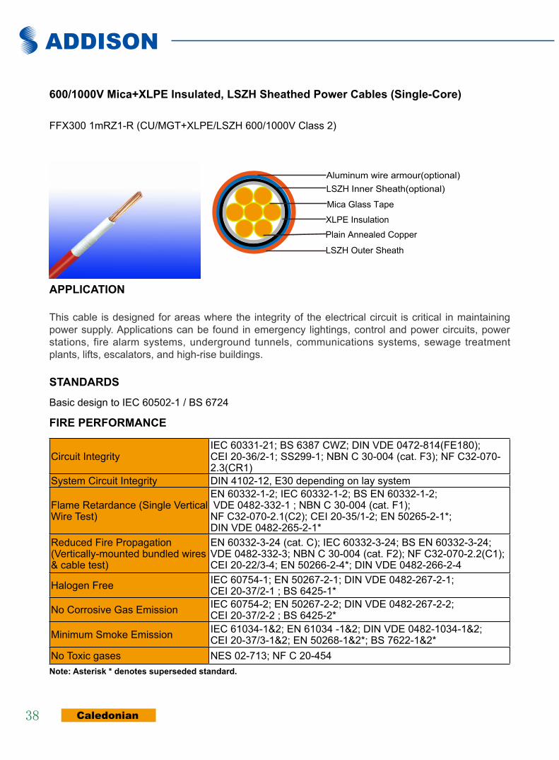
ADDISON
Caledonian38
600/1000V Mica+xlPe insulated, lsZH sheathed Power cables (single-core)
FFX300 1mRZ1-R (CU/MGT+XLPE/LSZH 600/1000V Class 2)
Mica Glass Tape
Plain Annealed Copper
XLPE Insulation
LSZH Outer Sheath
Aluminum wire armour(optional)LSZH Inner Sheath(optional)
aPPlicaTiOn
This cable is designed for areas where the integrity of the electrical circuit is critical in maintaining power supply. Applications can be found in emergency lightings, control and power circuits, power stations, fire alarm systems, underground tunnels, communications systems, sewage treatment plants, lifts, escalators, and high-rise buildings.
sTanDaRDs
Basic design to IEC 60502-1 / BS 6724
fiRe PeRfORMance
Circuit IntegrityIEC 60331-21; BS 6387 CWZ; DIN VDE 0472-814(FE180); CEI 20-36/2-1; SS299-1; NBN C 30-004 (cat. F3); NF C32-070-2.3(CR1)
System Circuit Integrity DIN 4102-12, E30 depending on lay system
Flame Retardance (Single Vertical Wire Test)
EN 60332-1-2; IEC 60332-1-2; BS EN 60332-1-2; VDE 0482-332-1 ; NBN C 30-004 (cat. F1); NF C32-070-2.1(C2); CEI 20-35/1-2; EN 50265-2-1*; DIN VDE 0482-265-2-1*
Reduced Fire Propagation (Vertically-mounted bundled wires & cable test)
EN 60332-3-24 (cat. C); IEC 60332-3-24; BS EN 60332-3-24; VDE 0482-332-3; NBN C 30-004 (cat. F2); NF C32-070-2.2(C1); CEI 20-22/3-4; EN 50266-2-4*; DIN VDE 0482-266-2-4
Halogen Free IEC 60754-1; EN 50267-2-1; DIN VDE 0482-267-2-1; CEI 20-37/2-1 ; BS 6425-1*
No Corrosive Gas Emission IEC 60754-2; EN 50267-2-2; DIN VDE 0482-267-2-2; CEI 20-37/2-2 ; BS 6425-2*
Minimum Smoke Emission IEC 61034-1&2; EN 61034 -1&2; DIN VDE 0482-1034-1&2; CEI 20-37/3-1&2; EN 50268-1&2*; BS 7622-1&2*
No Toxic gases NES 02-713; NF C 20-454note: asterisk * denotes superseded standard.

www.caledonian-cables.co.uk www.addison-cables.com
Caledonian
39ADDISON
fire Resistant Power & control cables
VOlTaGe RaTinG
600/1000 V
cable cOnsTRUcTiOn
conductor: Plain annealed copper wire, stranded according to IEC 60228 class 2.insulation: Mica glass tape covered by extruded cross-linked XLPE compoundOuter sheath:Thermoplastic LSZH compound type LTS3 as per BS 7655-6.1 (Thermosetting LSZH compound type SW2-SW4 as per BS 7655-2.6 can be offered.). UV resistance, hydrocarbon resistance, oil resistance, anti rodent and anti termite properties can be offered as option.
cOlOUR cODe
insulation colour: Natural (other colors upon request)sheath colour: Black (other colors upon request)
PHysical anD THeRMal PROPeRTies
Temperature range during operation (fixed state): -30°C – +90°C Temperature range during installation (mobile state): -20°C – +50°C Minimum bending radius: 8 x Overall Diameter (unarmoured cable) 10 x Overall Diameter (armoured cable)
elecTRical PROPeRTies
Dielectric test: 3500 V r.m.s. x 5’ (core/core)Insulation resistance 1000 MΩ x km (at 20°C)Short circuit temperature 250°C
cOnsTRUcTiOn PaRaMeTeRs
Conductor FFX300 1mRZ1-RNominal Cross
Section Area
No./Nominal Diameter of
Strands
Dia. of Conductor
Nominal Insulation Thickness
Approx. Overall
Diameter
Approx. Weight
mm2 No./mm mm mm mm kg/km1.5 7/0.53 1.59 0.7 6.5 542.5 7/0.67 2.01 0.7 6.8 674 7/0.85 2.55 0.7 7.5 866 7/1.04 3.12 0.7 8.1 11010 7/1.35 4.05 0.7 9.2 15516 7/1.70 5.1 0.7 10.2 22025 7/2.14 6.42 0.9 11.9 32535 19/1.53 7.65 0.9 13.2 42550 19/1.78 8.9 1 14.6 60070 19/2.14 10.7 1.1 16.6 82095 19/2.52 12.6 1.1 18.7 1100

ADDISON
Caledonian40
Conductor FFX300 1mRZ1-RNominal Cross
Section Area
No./Nominal Diameter of
Strands
Dia. of Conductor
Nominal Insulation Thickness
Approx. Overall
Diameter
Approx. Weight
mm2 No./mm mm mm mm kg/km120 37/2.03 14.21 1.2 20.5 1350150 37/2.25 15.75 1.4 22.7 1640185 37.2.52 17.64 1.6 25.5 2040240 61/2.25 20.25 1.7 28.5 2650300 61/2.52 22.68 1.8 31.5 3260400 65/2.85 25.65 2 35.4 4130500 61/3.20 28.8 2.2 39 5200630 127/2.52 32.76 2.4 43.5 6600800 127/2.85 37.05 2.6 48.5 83001000 127/3.20 41.6 2.8 53.5 10000
elecTRical PROPeRTies
conductor Operating Temperature : 90°C ambient Temperature : 30°C
current-carrying capacities (amp)
Conductor cross-section
area
Reference Method 4 (enclosed in conduit
in thermally insulating wall
etc)
Reference Method 3
(enclosed in conduit on a wall
or in trunking etc)
Reference Method 1 (clipped direct)
Reference Method 11 (on a perforated cable tray, horizontal or
vertical)
Reference Method 12 (free air)
Horizontal flat spaced
Vertical flat spaced Trefoil
2 cables, single-phase a.c. or
d.c.
3 or 4 cables, 3-phase
a.c.
2 cables, single-phase a.c. or
d.c
3 or 4 cables, 3-phase
a.c.
2 cables, single-
phase a.c. or d.c. flat and touching
3 or 4 cables, 3-phase a.c. flat
and touching or trefoil
2 cables, single-
phase a.c. or d.c. or flat and touching
3 or 4 cables, 3-phase a.c. flat
and touching or trefoil
2 cables, single-
phase a.c. or d.c. or 3 cables
three phase
2 cables, single-
phase a.c. or d.c. or 3
cables three phase
3 cables, trefoil
3-phase a.c.
1 2 3 4 5 6 7 8 9 10 11 12
mm2 A A A A A A A A A A A
1.5 18 17 22 19 25 23 - - - - -
2.5 24 23 30 26 34 31 - - - - -
4 33 30 40 35 46 41 - - - - -
6 43 39 51 45 59 54 - - - - -
10 58 53 71 63 81 74 - - - - -
16 76 70 95 85 109 99 - - - - -
25 100 91 126 111 143 130 158 140 183 163 138
35 125 111 156 138 176 161 195 176 226 203 171
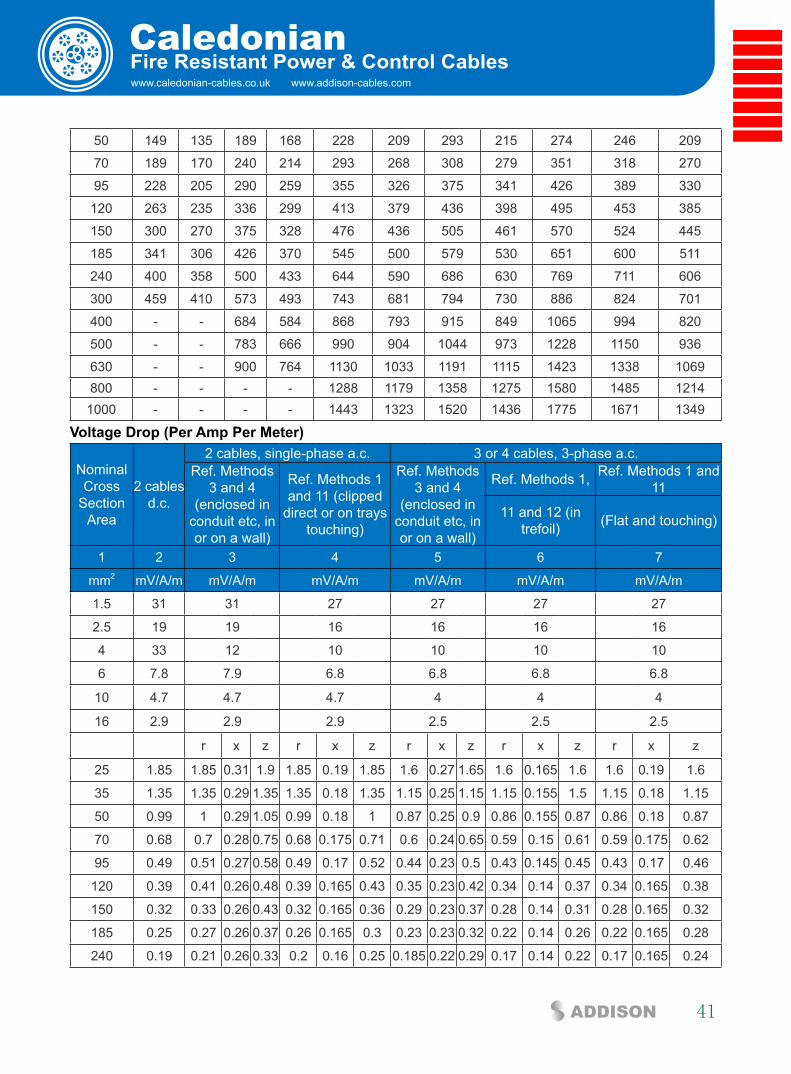
www.caledonian-cables.co.uk www.addison-cables.com
Caledonian
41ADDISON
fire Resistant Power & control cables
50 149 135 189 168 228 209 293 215 274 246 209
70 189 170 240 214 293 268 308 279 351 318 270
95 228 205 290 259 355 326 375 341 426 389 330
120 263 235 336 299 413 379 436 398 495 453 385
150 300 270 375 328 476 436 505 461 570 524 445
185 341 306 426 370 545 500 579 530 651 600 511
240 400 358 500 433 644 590 686 630 769 711 606
300 459 410 573 493 743 681 794 730 886 824 701
400 - - 684 584 868 793 915 849 1065 994 820
500 - - 783 666 990 904 1044 973 1228 1150 936
630 - - 900 764 1130 1033 1191 1115 1423 1338 1069800 - - - - 1288 1179 1358 1275 1580 1485 12141000 - - - - 1443 1323 1520 1436 1775 1671 1349
Voltage Drop (Per amp Per Meter)
Nominal Cross
Section Area
2 cables d.c.
2 cables, single-phase a.c. 3 or 4 cables, 3-phase a.c.Ref. Methods
3 and 4 (enclosed in
conduit etc, in or on a wall)
Ref. Methods 1 and 11 (clipped
direct or on trays touching)
Ref. Methods 3 and 4
(enclosed in conduit etc, in or on a wall)
Ref. Methods 1, Ref. Methods 1 and 11
11 and 12 (in trefoil) (Flat and touching)
1 2 3 4 5 6 7
mm2 mV/A/m mV/A/m mV/A/m mV/A/m mV/A/m mV/A/m
1.5 31 31 27 27 27 27
2.5 19 19 16 16 16 16
4 33 12 10 10 10 10
6 7.8 7.9 6.8 6.8 6.8 6.8
10 4.7 4.7 4.7 4 4 4
16 2.9 2.9 2.9 2.5 2.5 2.5
r x z r x z r x z r x z r x z
25 1.85 1.85 0.31 1.9 1.85 0.19 1.85 1.6 0.27 1.65 1.6 0.165 1.6 1.6 0.19 1.6
35 1.35 1.35 0.29 1.35 1.35 0.18 1.35 1.15 0.25 1.15 1.15 0.155 1.5 1.15 0.18 1.15
50 0.99 1 0.29 1.05 0.99 0.18 1 0.87 0.25 0.9 0.86 0.155 0.87 0.86 0.18 0.87
70 0.68 0.7 0.28 0.75 0.68 0.175 0.71 0.6 0.24 0.65 0.59 0.15 0.61 0.59 0.175 0.62
95 0.49 0.51 0.27 0.58 0.49 0.17 0.52 0.44 0.23 0.5 0.43 0.145 0.45 0.43 0.17 0.46
120 0.39 0.41 0.26 0.48 0.39 0.165 0.43 0.35 0.23 0.42 0.34 0.14 0.37 0.34 0.165 0.38
150 0.32 0.33 0.26 0.43 0.32 0.165 0.36 0.29 0.23 0.37 0.28 0.14 0.31 0.28 0.165 0.32
185 0.25 0.27 0.26 0.37 0.26 0.165 0.3 0.23 0.23 0.32 0.22 0.14 0.26 0.22 0.165 0.28
240 0.19 0.21 0.26 0.33 0.2 0.16 0.25 0.185 0.22 0.29 0.17 0.14 0.22 0.17 0.165 0.24
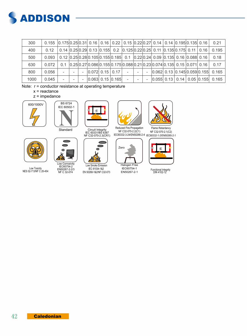
ADDISON
Caledonian42
300 0.155 0.175 0.25 0.31 0.16 0.16 0.22 0.15 0.22 0.27 0.14 0.14 0.195 0.135 0.16 0.21
400 0.12 0.14 0.25 0.29 0.13 0.155 0.2 0.125 0.22 0.25 0.11 0.135 0.175 0.11 0.16 0.195
500 0.093 0.12 0.25 0.28 0.105 0.155 0.185 0.1 0.22 0.24 0.09 0.135 0.16 0.088 0.16 0.18
630 0.072 0.1 0.25 0.27 0.086 0.155 0.175 0.088 0.21 0.23 0.074 0.135 0.15 0.071 0.16 0.17
800 0.056 - - - 0.072 0.15 0.17 - - - 0.062 0.13 0.145 0.059 0.155 0.165
1000 0.045 - - - 0.063 0.15 0.165 - - - 0.055 0.13 0.14 0.05 0.155 0.165
Note: r = conductor resistance at operating temperature x = reactance z = impedance
Rated Voltage
600/1000V
NStandard
BS 6724IEC 60502-1
Circuit IntegrityIEC 60331/BS 6387
NF C32-070-2.3(CR1)
W E
Reduced Fire PropagationNF C32-070-2.2(C1)
IEC60332-3-24/EN50266-2-4
Flame RetardancyNF C32-070-2.1(C2)
IEC60332-1-2/EN50265-2-1
Low ToxicityNES 02-713/NF C 20-454
Low CorrosivityIEC60754-2
EN50267-2-2/3NF C 32-074
Low Smoke EmissionIEC 61034-1&2
EN 50268-1&2/NF C32-073
Zero
Halogen FreeIEC60754-1
EN50267-2-1
W E
DIN 4102-12Functional Integrity
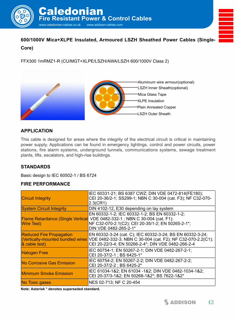
www.caledonian-cables.co.uk www.addison-cables.com
Caledonian
43ADDISON
fire Resistant Power & control cables
600/1000V Mica+xlPe insulated, armoured lsZH sheathed Power cables (single-core)
FFX300 1mRMZ1-R (CU/MGT+XLPE/LSZH/AWA/LSZH 600/1000V Class 2)
Mica Glass Tape
Plain Annealed Copper
XLPE Insulation
LSZH Outer Sheath
Aluminum wire armour(optional)LSZH Inner Sheath(optional)
aPPlicaTiOn
This cable is designed for areas where the integrity of the electrical circuit is critical in maintaining power supply. Applications can be found in emergency lightings, control and power circuits, power stations, fire alarm systems, underground tunnels, communications systems, sewage treatment plants, lifts, escalators, and high-rise buildings.
sTanDaRDs
Basic design to IEC 60502-1 / BS 6724
fiRe PeRfORMance
Circuit IntegrityIEC 60331-21; BS 6387 CWZ; DIN VDE 0472-814(FE180); CEI 20-36/2-1; SS299-1; NBN C 30-004 (cat. F3); NF C32-070-2.3(CR1)
System Circuit Integrity DIN 4102-12, E30 depending on lay system
Flame Retardance (Single Vertical Wire Test)
EN 60332-1-2; IEC 60332-1-2; BS EN 60332-1-2; VDE 0482-332-1 ; NBN C 30-004 (cat. F1); NF C32-070-2.1(C2); CEI 20-35/1-2; EN 50265-2-1*; DIN VDE 0482-265-2-1*
Reduced Fire Propagation (Vertically-mounted bundled wires & cable test)
EN 60332-3-24 (cat. C); IEC 60332-3-24; BS EN 60332-3-24; VDE 0482-332-3; NBN C 30-004 (cat. F2); NF C32-070-2.2(C1); CEI 20-22/3-4; EN 50266-2-4*; DIN VDE 0482-266-2-4
Halogen Free IEC 60754-1; EN 50267-2-1; DIN VDE 0482-267-2-1; CEI 20-37/2-1 ; BS 6425-1*
No Corrosive Gas Emission IEC 60754-2; EN 50267-2-2; DIN VDE 0482-267-2-2; CEI 20-37/2-2 ; BS 6425-2*
Minimum Smoke Emission IEC 61034-1&2; EN 61034 -1&2; DIN VDE 0482-1034-1&2; CEI 20-37/3-1&2; EN 50268-1&2*; BS 7622-1&2*
No Toxic gases NES 02-713; NF C 20-454note: asterisk * denotes superseded standard.
ADDISON
Caledonian44
VOlTaGe RaTinG
600/1000 V
cable cOnsTRUcTiOn
conductor: Plain annealed copper wire, stranded according to IEC 60228 class 2.insulation: Mica glass tape covered by extruded cross-linked XLPE compoundinner sheath (optional):Thermoplastic LSZH compound type LTS3 as per BS 7655-6.1 armouring (optional): Aluminum wire armourOuter sheath:Thermoplastic LSZH compound type LTS3 as per BS 7655-6.1 (Thermosetting LSZH compound type SW2-SW4 as per BS 7655-2.6 can be offered.). UV resistance, hydrocarbon resistance, oil resistance, anti rodent and anti termite properties can be offered as option.
cOlOUR cODe
insulation colour: Natural (other colors upon request)sheath colour: Black (other colors upon request)
PHysical anD THeRMal PROPeRTies
Temperature range during operation (fixed state): -30°C – +90°C Temperature range during installation (mobile state): -20°C – +50°C Minimum bending radius: 8 x Overall Diameter (unarmoured cable) 10 x Overall Diameter (armoured cable)
elecTRical PROPeRTies
Dielectric test: 3500 V r.m.s. x 5’ (core/core)Insulation resistance 1000 MΩ x km (at 20°C)Short circuit temperature 250°C
cOnsTRUcTiOn PaRaMeTeRs
Conductor FFX300 1mRMZ1-RNominal Cross
Section Area
No./Nominal Diameter of
Strands
Dia. of Conductor
Nominal Insulation Thickness
Approx. Overall
Diameter
Approx. Weight
mm2 No./mm mm mm mm kg/km50 19/1.78 8.9 1 18.5 78070 19/2.14 10.7 1.1 20.5 101095 19/2.52 12.6 1.1 23 1320120 37/2.03 14.21 1.2 24.5 1610150 37/2.25 15.75 1.4 27 2010185 37.2.52 17.64 1.6 29.5 2440240 61/2.25 20.25 1.7 34.5 3060300 61/2.52 22.68 1.8 36.9 3690400 65/2.85 25.65 2 41.5 4780
www.caledonian-cables.co.uk www.addison-cables.com
Caledonian
45ADDISON
fire Resistant Power & control cables
500 61/3.20 28.8 2.2 45.5 5970630 127/2.52 32.76 2.4 50.5 7530800 127/2.85 37.05 2.6 56.8 96801000 127/3.20 41.6 2.8 61.5 11980
elecTRical PROPeRTies
conductor Operating Temperature : 90°C ambient Temperature : 30°C
current-carrying capacities (amp)
Nominal Cross
Section Area
Reference Method 1(clipped direct)
Reference Method 11 (on
perforated cable tray)
ReferenceMethod 12(free air)
In single-way ducts Laid direct in ground
2 cablessinglephase
a.c.or d.c.flat andtouching
3 or 4cables
3-phasea.c. flat
andtouching
2 cablessinglephase
a.c.or d.c.flat andtouching
3 or 4cables
3-phasea.c. flat
andtouching
3 cables3-phase
a.c. trefoiltouching
2 cablessinglephase
a.c.or d.c. ducts
touching
3 cables3-phase
a.c. trefoiltouching
2 cablessinglephase
a.c.or d.c.
touching
3 cables3-phase
a.c. trefoiltouching
1 2 3 4 5 6 7 8 9 10
mm2 A A A A A A A A A
50 237 220 253 232 222 255 235 275 235
70 303 277 322 293 285 310 280 340 290
95 367 333 389 352 346 365 330 405 345
120 425 383 449 405 402 410 370 460 389
150 488 437 516 462 463 445 405 510 435
185 557 496 587 524 529 485 440 580 490
240 656 579 689 612 625 550 500 670 560
300 755 662 792 700 720 610 550 750 630
400 853 717 899 767 815 640 580 830 700
500 962 791 1016 851 918 690 620 910 770
630 1082 861 1146 935 1027 750 670 1000 840
800 1170 904 1246 987 1119 828 735 1117 931
1000 1261 961 1345 1055 1214 919 811 1254 1038
Voltage Drop (Per amp Per Meter) Nominal Cross
Section Area
2 cables
d.c.
2 cables single-phasea.c.
3 or 4 cables three-phase a.c.2 cables
singlephasea.c.
3 or 4 cables,3-phase a.c.
touching

ADDISON
Caledonian46
Reference Method 1 &
11 (touching)
Reference Method 1, 11
& 12 (in trefoil touching)
Reference Method 1 & 11(Flat touching)
Inducts
Inground
Inducts
Inground
1 2 3 4 5 6 7 8 9
mm2 mV/A/m mV/A/m mV/A/m mV/A/m mV/
A/mmV/A/
mmV/A/m
mV/A/m
r x z r x z r x z
50 0.98 0.99 0.21 1 0.86 0.18 0.87 0.84 0.25 0.88 1.1 0.99 0.93 0.8670 0.67 0.68 0.2 0.71 0.59 0.17 0.62 0.6 0.25 0.65 0.8 0.7 0.7 0.6195 0.49 0.51 0.195 0.55 0.44 0.17 0.47 0.46 0.24 0.52 0.65 0.53 0.56 0.46120 0.39 0.41 0.19 0.45 0.35 0.165 0.39 0.38 0.24 0.44 0.55 0.43 0.48 0.37150 0.31 0.33 0.185 0.38 0.29 0.16 0.33 0.31 0.23 0.39 0.5 0.37 0.43 0.32185 0.25 0.27 0.185 0.33 0.23 0.16 0.28 0.26 0.23 0.34 0.45 0.31 0.39 0.27240 0.195 0.21 0.18 0.28 0.18 0.155 0.24 0.21 0.22 0.3 0.4 0.26 0.35 0.23300 0.155 0.17 0.175 0.25 0.145 0.15 0.21 0.17 0.22 0.28 0.37 0.24 0.32 0.21400 0.115 0.145 0.17 0.22 0.125 0.15 0.195 0.16 0.21 0.27 0.35 0.21 0.3 0.19500 0.093 0.125 0.17 0.21 0.105 0.145 0.18 0.145 0.2 0.25 0.33 0.2 0.28 0.18630 0.073 0.105 0.165 0.195 0.092 0.145 0.17 0.135 0.1950.24 0.3 0.19 0.26 0.17800 0.056 0.09 0.16 0.19 0.086 0.14 0.165 0.13 0.18 0.23 0.28 0.18 0.24 0.161000 0.045 0.092 0.155 0.18 0.08 0.135 0.155 0.125 0.17 0.21 0.26 0.17 0.22 0.15
Note: r = conductor resistance at operating temperature x = reactance z = impedance
Rated Voltage
600/1000V
NStandard
BS 6724IEC 60502-1
Circuit IntegrityIEC 60331/BS 6387
NF C32-070-2.3(CR1)
W E
Reduced Fire PropagationNF C32-070-2.2(C1)
IEC60332-3-24/EN50266-2-4
Flame RetardancyNF C32-070-2.1(C2)
IEC60332-1-2/EN50265-2-1
Low ToxicityNES 02-713/NF C 20-454
Low CorrosivityIEC60754-2
EN50267-2-2/3NF C 32-074
Low Smoke EmissionIEC 61034-1&2
EN 50268-1&2/NF C32-073
Zero
Halogen FreeIEC60754-1
EN50267-2-1
W E
DIN 4102-12Functional Integrity
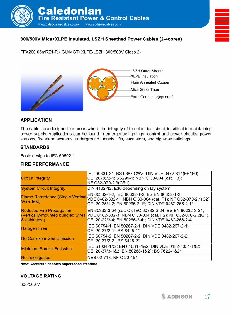
www.caledonian-cables.co.uk www.addison-cables.com
Caledonian
47ADDISON
fire Resistant Power & control cables
300/500V Mica+xlPe insulated, lsZH sheathed Power cables (2-4cores)
FFX200 05mRZ1-R ( CU/MGT+XLPE/LSZH 300/500V Class 2)
XLPE Insulation
Mica Glass Tape
Plain Annealed Copper
LSZH Outer Sheath
Earth Conductor(optional)
aPPlicaTiOn
The cables are designed for areas where the integrity of the electrical circuit is critical in maintaining power supply. Applications can be found in emergency lightings, control and power circuits, power stations, fire alarm systems, underground tunnels, lifts, escalators, and high-rise buildings.
sTanDaRDs
Basic design to IEC 60502-1
fiRe PeRfORMance
Circuit IntegrityIEC 60331-21; BS 6387 CWZ; DIN VDE 0472-814(FE180); CEI 20-36/2-1; SS299-1; NBN C 30-004 (cat. F3); NF C32-070-2.3(CR1)
System Circuit Integrity DIN 4102-12, E30 depending on lay system
Flame Retardance (Single Vertical Wire Test)
EN 60332-1-2; IEC 60332-1-2; BS EN 60332-1-2; VDE 0482-332-1 ; NBN C 30-004 (cat. F1); NF C32-070-2.1(C2); CEI 20-35/1-2; EN 50265-2-1*; DIN VDE 0482-265-2-1*
Reduced Fire Propagation (Vertically-mounted bundled wires & cable test)
EN 60332-3-24 (cat. C); IEC 60332-3-24; BS EN 60332-3-24; VDE 0482-332-3; NBN C 30-004 (cat. F2); NF C32-070-2.2(C1); CEI 20-22/3-4; EN 50266-2-4*; DIN VDE 0482-266-2-4
Halogen Free IEC 60754-1; EN 50267-2-1; DIN VDE 0482-267-2-1; CEI 20-37/2-1 ; BS 6425-1*
No Corrosive Gas Emission IEC 60754-2; EN 50267-2-2; DIN VDE 0482-267-2-2; CEI 20-37/2-2 ; BS 6425-2*
Minimum Smoke Emission IEC 61034-1&2; EN 61034 -1&2; DIN VDE 0482-1034-1&2; CEI 20-37/3-1&2; EN 50268-1&2*; BS 7622-1&2*
No Toxic gases NES 02-713; NF C 20-454note: asterisk * denotes superseded standard.
VOlTaGe RaTinG
300/500 V
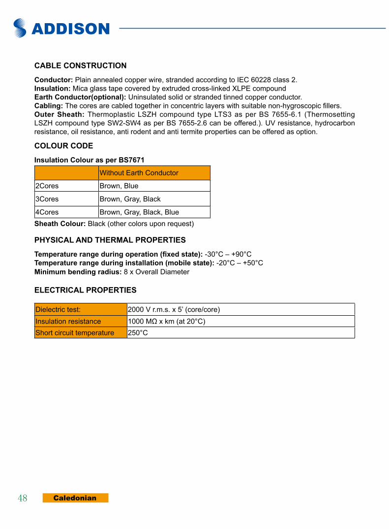
ADDISON
Caledonian48
cable cOnsTRUcTiOn
conductor: Plain annealed copper wire, stranded according to IEC 60228 class 2.insulation: Mica glass tape covered by extruded cross-linked XLPE compoundearth conductor(optional): Uninsulated solid or stranded tinned copper conductor.cabling: The cores are cabled together in concentric layers with suitable non-hygroscopic fillers.Outer sheath: Thermoplastic LSZH compound type LTS3 as per BS 7655-6.1 (Thermosetting LSZH compound type SW2-SW4 as per BS 7655-2.6 can be offered.). UV resistance, hydrocarbon resistance, oil resistance, anti rodent and anti termite properties can be offered as option.
cOlOUR cODe
insulation colour as per bs7671
Without Earth Conductor
2Cores Brown, Blue
3Cores Brown, Gray, Black
4Cores Brown, Gray, Black, Bluesheath colour: Black (other colors upon request)
PHysical anD THeRMal PROPeRTies
Temperature range during operation (fixed state): -30°C – +90°C Temperature range during installation (mobile state): -20°C – +50°C Minimum bending radius: 8 x Overall Diameter
elecTRical PROPeRTies
Dielectric test: 2000 V r.m.s. x 5’ (core/core)Insulation resistance 1000 MΩ x km (at 20°C)Short circuit temperature 250°C

www.caledonian-cables.co.uk www.addison-cables.com
Caledonian
49ADDISON
fire Resistant Power & control cables
cOnsTRUcTiOn PaRaMeTeRs
ConductorFFX200 05mRZ1-R
Without Earth Conductor
With Earth Conductor
No. of Core X Cross Section
No./Nominal Diameter of
Strands
Nominal Insulation Thickness
Nominal Sheath
Thickness
Nominal Overall
Diameter
Approx. Weight
Nominal Overall
Diameter
Approx. Weight
No*mm2 No./mm mm mm mm kg/km mm kg/km2 core
2x1.5 7/0.53 0.5 0.5 7.7 70 8.2 802x2.5 7/0.67 0.5 0.5 8.8 100 9.6 1202x4 7/0.85 0.5 0.5 9.8 140 10.5 170
3 core3x1.5 7/0.53 0.5 0.5 8.7 90 10.5 1003x2.5 7/0.67 0.5 0.5 9.5 125 10.7 1503x4 7/0.85 0.5 0.5 11.5 180 12.5 220
4 core4x1.5 7/0.53 0.5 0.5 10.3 105 12.2 1204x2.5 7/0.67 0.5 0.5 11 155 13 1904x4 7/0.85 0.5 0.5 12.5 255 13.5 270
elecTRical PROPeRTies
conductor Operating Temperature : 90°C ambient Temperature : 30°C current-carrying capacities (amp)
Nominalcross-section
area
Reference Method 4
(enclosed in an conduit
insulated wall etc)
Reference Method 3(enclosed in conduit on a wall or ceiling, or in
trunking)
Reference Method 1 (clipped direct)
Reference Method 11(on a perforated cable
tray), or Reference Method 13 (free air)
one 3-core cable or one 4-core cable 3-phase a.c.
one 2-core cable
singlephase a.c. or d.c.
one 3-core cable or one 4-core cable 3-phase a.c.
one 2-core cable
singlephase a.c. or d.c.
one 3-core cable or one 4-core cable 3-phase a.c.
one 2-corecable
singlephasea.c. or
d.c.
one 3-corecable or one4-core cable3-phase a.c.
1 2 3 4 5 6 7 8
mm2 A A A A A A A
1.5 16.5 22 19.5 24 22 26 23
2.5 22 30 26 33 30 36 32
4 30 40 35 45 40 49 42
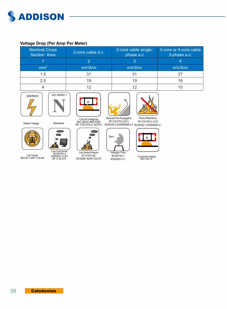
ADDISON
Caledonian50
Voltage Drop (Per amp Per Meter)Nominal CrossSection Area 2-core cable d.c. 2-core cable single-
phase a.c3-core or 4-core cable
3-phase a.c.1 2 3 4
mm2 mV/A/m mV/A/m mV/A/m1.5 31 31 272.5 19 19 164 12 12 10
Rated Voltage
300/500V
NStandard
IEC 60502-1
Circuit IntegrityIEC 60331/BS 6387
NF C32-070-2.3(CR1)
W E
Reduced Fire PropagationNF C32-070-2.2(C1)
IEC60332-3-24/EN50266-2-4
Flame RetardancyNF C32-070-2.1(C2)
IEC60332-1-2/EN50265-2-1
Low ToxicityNES 02-713/NF C 20-454
Low CorrosivityIEC60754-2
EN50267-2-2/3NF C 32-074
Low Smoke EmissionIEC 61034-1&2
EN 50268-1&2/NF C32-073
Zero
Halogen FreeIEC60754-1
EN50267-2-1
W E
DIN 4102-12Functional Integrity
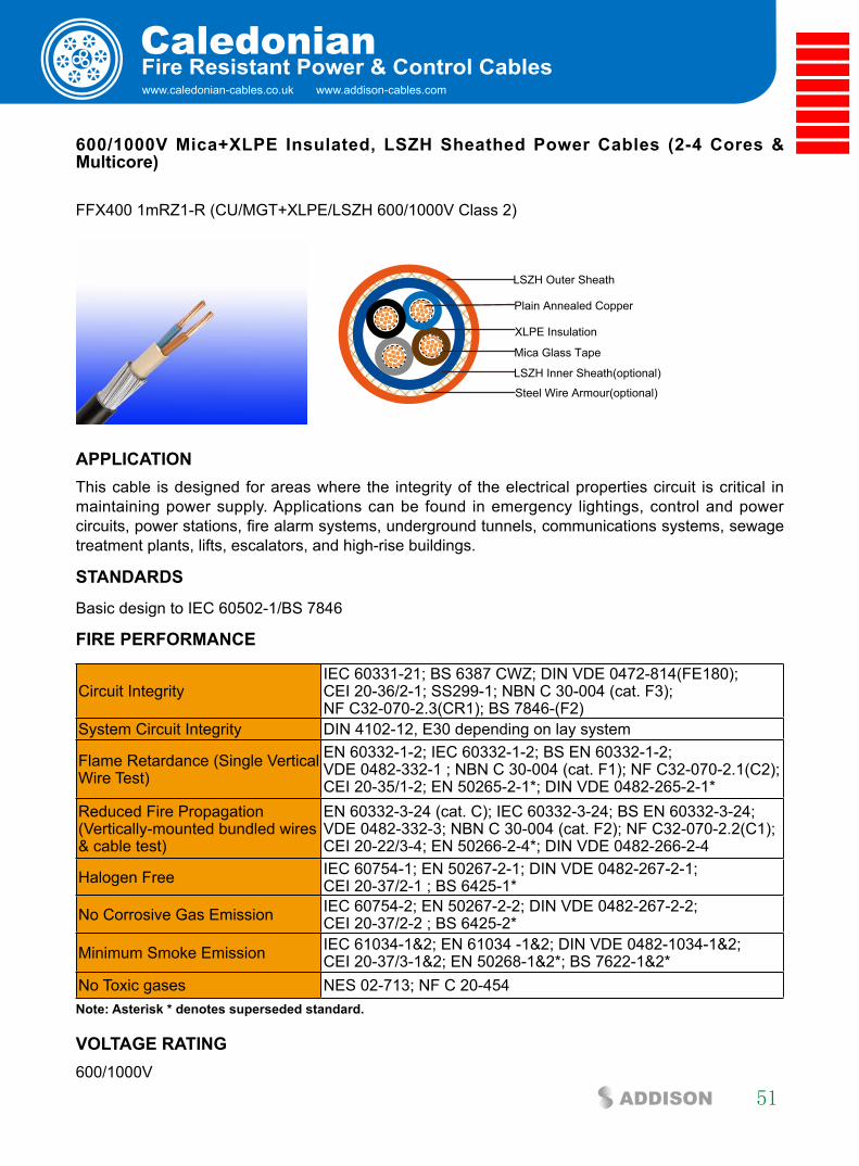
www.caledonian-cables.co.uk www.addison-cables.com
Caledonian
51ADDISON
fire Resistant Power & control cables
600/1000V Mica+xlPe insulated, lsZH sheathed Power cables (2-4 cores & Multicore)
FFX400 1mRZ1-R (CU/MGT+XLPE/LSZH 600/1000V Class 2)
LSZH Outer Sheath
Plain Annealed Copper
Mica Glass Tape
XLPE Insulation
Steel Wire Armour(optional)
LSZH Inner Sheath(optional)
aPPlicaTiOn This cable is designed for areas where the integrity of the electrical properties circuit is critical in maintaining power supply. Applications can be found in emergency lightings, control and power circuits, power stations, fire alarm systems, underground tunnels, communications systems, sewage treatment plants, lifts, escalators, and high-rise buildings.
sTanDaRDs
Basic design to IEC 60502-1/BS 7846
fiRe PeRfORMance
Circuit IntegrityIEC 60331-21; BS 6387 CWZ; DIN VDE 0472-814(FE180); CEI 20-36/2-1; SS299-1; NBN C 30-004 (cat. F3); NF C32-070-2.3(CR1); BS 7846-(F2)
System Circuit Integrity DIN 4102-12, E30 depending on lay system
Flame Retardance (Single Vertical Wire Test)
EN 60332-1-2; IEC 60332-1-2; BS EN 60332-1-2; VDE 0482-332-1 ; NBN C 30-004 (cat. F1); NF C32-070-2.1(C2); CEI 20-35/1-2; EN 50265-2-1*; DIN VDE 0482-265-2-1*
Reduced Fire Propagation (Vertically-mounted bundled wires & cable test)
EN 60332-3-24 (cat. C); IEC 60332-3-24; BS EN 60332-3-24; VDE 0482-332-3; NBN C 30-004 (cat. F2); NF C32-070-2.2(C1); CEI 20-22/3-4; EN 50266-2-4*; DIN VDE 0482-266-2-4
Halogen Free IEC 60754-1; EN 50267-2-1; DIN VDE 0482-267-2-1; CEI 20-37/2-1 ; BS 6425-1*
No Corrosive Gas Emission IEC 60754-2; EN 50267-2-2; DIN VDE 0482-267-2-2; CEI 20-37/2-2 ; BS 6425-2*
Minimum Smoke Emission IEC 61034-1&2; EN 61034 -1&2; DIN VDE 0482-1034-1&2; CEI 20-37/3-1&2; EN 50268-1&2*; BS 7622-1&2*
No Toxic gases NES 02-713; NF C 20-454note: asterisk * denotes superseded standard.
VOlTaGe RaTinG 600/1000V
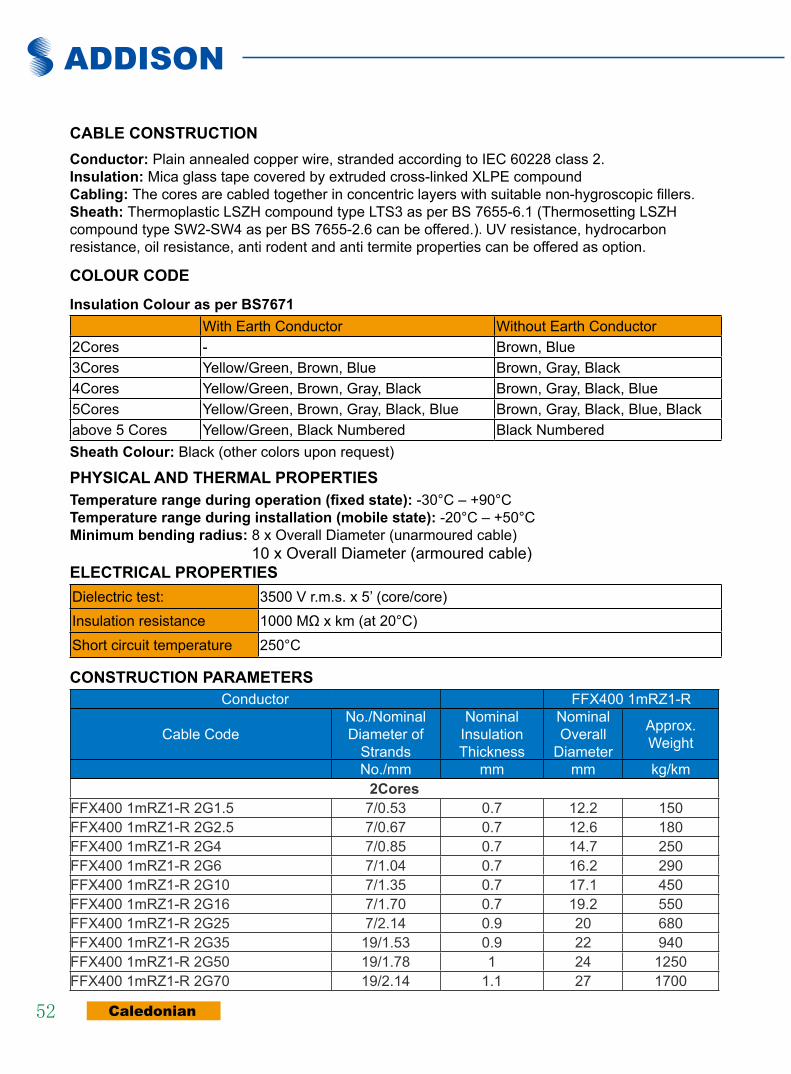
ADDISON
Caledonian52
cable cOnsTRUcTiOn conductor: Plain annealed copper wire, stranded according to IEC 60228 class 2.insulation: Mica glass tape covered by extruded cross-linked XLPE compoundcabling: The cores are cabled together in concentric layers with suitable non-hygroscopic fillers.sheath: Thermoplastic LSZH compound type LTS3 as per BS 7655-6.1 (Thermosetting LSZH compound type SW2-SW4 as per BS 7655-2.6 can be offered.). UV resistance, hydrocarbon resistance, oil resistance, anti rodent and anti termite properties can be offered as option.
cOlOUR cODe
insulation colour as per bs7671With Earth Conductor Without Earth Conductor
2Cores - Brown, Blue3Cores Yellow/Green, Brown, Blue Brown, Gray, Black4Cores Yellow/Green, Brown, Gray, Black Brown, Gray, Black, Blue5Cores Yellow/Green, Brown, Gray, Black, Blue Brown, Gray, Black, Blue, Blackabove 5 Cores Yellow/Green, Black Numbered Black Numberedsheath colour: Black (other colors upon request)
PHysical anD THeRMal PROPeRTiesTemperature range during operation (fixed state): -30°C – +90°C Temperature range during installation (mobile state): -20°C – +50°C Minimum bending radius: 8 x Overall Diameter (unarmoured cable) 10 x Overall Diameter (armoured cable)elecTRical PROPeRTiesDielectric test: 3500 V r.m.s. x 5’ (core/core)Insulation resistance 1000 MΩ x km (at 20°C)Short circuit temperature 250°C
cOnsTRUcTiOn PaRaMeTeRsConductor FFX400 1mRZ1-R
Cable CodeNo./Nominal Diameter of
Strands
Nominal Insulation Thickness
Nominal Overall
Diameter
Approx. Weight
No./mm mm mm kg/km2cores
FFX400 1mRZ1-R 2G1.5 7/0.53 0.7 12.2 150FFX400 1mRZ1-R 2G2.5 7/0.67 0.7 12.6 180FFX400 1mRZ1-R 2G4 7/0.85 0.7 14.7 250FFX400 1mRZ1-R 2G6 7/1.04 0.7 16.2 290FFX400 1mRZ1-R 2G10 7/1.35 0.7 17.1 450FFX400 1mRZ1-R 2G16 7/1.70 0.7 19.2 550FFX400 1mRZ1-R 2G25 7/2.14 0.9 20 680FFX400 1mRZ1-R 2G35 19/1.53 0.9 22 940FFX400 1mRZ1-R 2G50 19/1.78 1 24 1250FFX400 1mRZ1-R 2G70 19/2.14 1.1 27 1700

www.caledonian-cables.co.uk www.addison-cables.com
Caledonian
53ADDISON
fire Resistant Power & control cables
Conductor FFX400 1mRZ1-R
Cable CodeNo./Nominal Diameter of
Strands
Nominal Insulation Thickness
Nominal Overall
Diameter
Approx. Weight
No./mm mm mm kg/kmFFX400 1mRZ1-R 2G95 19/2.52 1.1 31 2300FFX400 1mRZ1-R 2G120 37/2.03 1.2 36 3150
3coresFFX400 1mRZ1-R 3G1.5 7/0.53 0.7 12.3 170FFX400 1mRZ1-R 3G2.5 7/0.67 0.7 13.8 200FFX400 1mRZ1-R 3G4 7/0.85 0.7 15.2 300FFX400 1mRZ1-R 3G6 7/1.04 0.7 16.8 380FFX400 1mRZ1-R 3G10 7/1.35 0.7 18 550FFX400 1mRZ1-R 3G16 1/1.70 0.7 21 760FFX400 1mRZ1-R 3G25 7/2.14 0.9 22 960FFX400 1mRZ1-R 3G35 19/1.53 0.9 24 1300FFX400 1mRZ1-R 3G50 19/1.78 1 28 1700FFX400 1mRZ1-R 3G70 19/2.14 1.1 31 2400FFX400 1mRZ1-R 3G95 19/2.52 1.1 36 3250FFX400 1mRZ1-R 3G120 37/2.03 1.2 38 4000FFX400 1mRZ1-R 3G150 37/2.25 1.4 42 5000FFX400 1mRZ1-R 3G185 37/2.52 1.6 47 6100FFX400 1mRZ1-R 3G240 61/2.25 1.7 52 8000FFX400 1mRZ1-R 3G300 61/2.52 1.8 59 9850FFX400 1mRZ1-R 3G400 61/2.85 2 63 13000
3cores+1core earth conductorFFX400 1mRZ1-R 3G10+6 7/1.35 0.7 18.6 580FFX400 1mRZ1-R 3G16+10 7/1.70 0.7 19.7 810FFX400 1mRZ1-R 3G25+10 7/2.14 0.9 22 1090FFX400 1mRZ1-R 3G25+16 7/2.14 0.9 23 1150FFX400 1mRZ1-R 3G35+16 19/1.53 0.9 26 1420FFX400 1mRZ1-R 3G35+25 19/1.53 0.9 27 1490FFX400 1mRZ1-R 3G50+16 19/1.78 1 29 1800FFX400 1mRZ1-R 3G50+25 19/1.78 1 30 1890FFX400 1mRZ1-R 3G50+35 19/1.78 1 31 1920FFX400 1mRZ1-R 3G70+16 19/2.14 1.1 32 2200FFX400 1mRZ1-R 3G70+25 19/2.14 1.1 33 2400FFX400 1mRZ1-R 3G70+35 19/2.14 1.1 35 2900FFX400 1mRZ1-R 3G70+50 19/2.14 1.1 36 3300FFX400 1mRZ1-R 3G95+16 19/2.52 1.1 37 3560FFX400 1mRZ1-R 3G95+25 19/2.52 1.1 38 3700FFX400 1mRZ1-R 3G95+35 19/2.52 1.1 39 3910FFX400 1mRZ1-R 3G95+50 19/2.52 1.1 40 4200FFX400 1mRZ1-R 3G120+35 37/2.03 1.2 40 4250
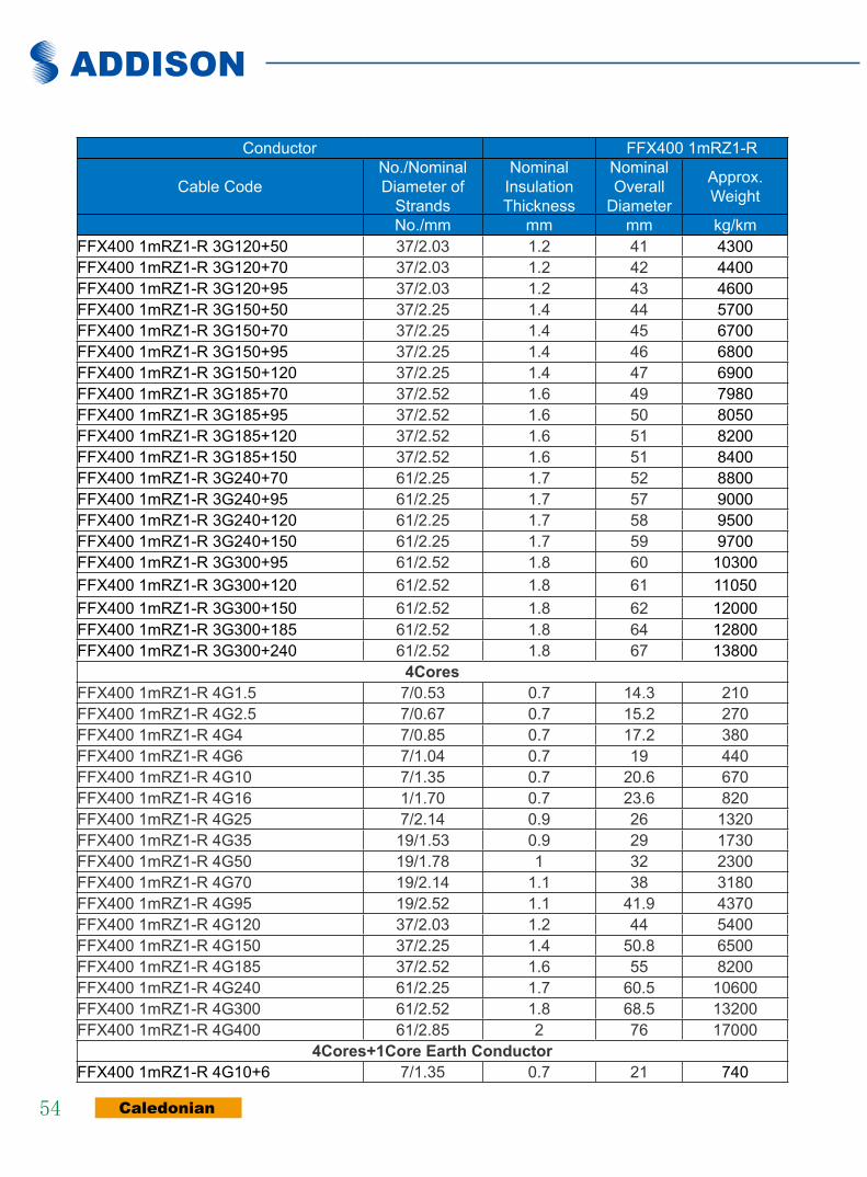
ADDISON
Caledonian54
Conductor FFX400 1mRZ1-R
Cable CodeNo./Nominal Diameter of
Strands
Nominal Insulation Thickness
Nominal Overall
Diameter
Approx. Weight
No./mm mm mm kg/kmFFX400 1mRZ1-R 3G120+50 37/2.03 1.2 41 4300FFX400 1mRZ1-R 3G120+70 37/2.03 1.2 42 4400FFX400 1mRZ1-R 3G120+95 37/2.03 1.2 43 4600FFX400 1mRZ1-R 3G150+50 37/2.25 1.4 44 5700FFX400 1mRZ1-R 3G150+70 37/2.25 1.4 45 6700FFX400 1mRZ1-R 3G150+95 37/2.25 1.4 46 6800FFX400 1mRZ1-R 3G150+120 37/2.25 1.4 47 6900FFX400 1mRZ1-R 3G185+70 37/2.52 1.6 49 7980FFX400 1mRZ1-R 3G185+95 37/2.52 1.6 50 8050FFX400 1mRZ1-R 3G185+120 37/2.52 1.6 51 8200FFX400 1mRZ1-R 3G185+150 37/2.52 1.6 51 8400FFX400 1mRZ1-R 3G240+70 61/2.25 1.7 52 8800FFX400 1mRZ1-R 3G240+95 61/2.25 1.7 57 9000FFX400 1mRZ1-R 3G240+120 61/2.25 1.7 58 9500FFX400 1mRZ1-R 3G240+150 61/2.25 1.7 59 9700FFX400 1mRZ1-R 3G300+95 61/2.52 1.8 60 10300FFX400 1mRZ1-R 3G300+120 61/2.52 1.8 61 11050FFX400 1mRZ1-R 3G300+150 61/2.52 1.8 62 12000FFX400 1mRZ1-R 3G300+185 61/2.52 1.8 64 12800FFX400 1mRZ1-R 3G300+240 61/2.52 1.8 67 13800
4coresFFX400 1mRZ1-R 4G1.5 7/0.53 0.7 14.3 210FFX400 1mRZ1-R 4G2.5 7/0.67 0.7 15.2 270FFX400 1mRZ1-R 4G4 7/0.85 0.7 17.2 380FFX400 1mRZ1-R 4G6 7/1.04 0.7 19 440FFX400 1mRZ1-R 4G10 7/1.35 0.7 20.6 670FFX400 1mRZ1-R 4G16 1/1.70 0.7 23.6 820FFX400 1mRZ1-R 4G25 7/2.14 0.9 26 1320FFX400 1mRZ1-R 4G35 19/1.53 0.9 29 1730FFX400 1mRZ1-R 4G50 19/1.78 1 32 2300FFX400 1mRZ1-R 4G70 19/2.14 1.1 38 3180FFX400 1mRZ1-R 4G95 19/2.52 1.1 41.9 4370FFX400 1mRZ1-R 4G120 37/2.03 1.2 44 5400FFX400 1mRZ1-R 4G150 37/2.25 1.4 50.8 6500FFX400 1mRZ1-R 4G185 37/2.52 1.6 55 8200FFX400 1mRZ1-R 4G240 61/2.25 1.7 60.5 10600FFX400 1mRZ1-R 4G300 61/2.52 1.8 68.5 13200FFX400 1mRZ1-R 4G400 61/2.85 2 76 17000
4cores+1core earth conductorFFX400 1mRZ1-R 4G10+6 7/1.35 0.7 21 740

www.caledonian-cables.co.uk www.addison-cables.com
Caledonian
55ADDISON
fire Resistant Power & control cables
Conductor FFX400 1mRZ1-R
Cable CodeNo./Nominal Diameter of
Strands
Nominal Insulation Thickness
Nominal Overall
Diameter
Approx. Weight
No./mm mm mm kg/kmFFX400 1mRZ1-R 4G16+10 7/1.70 0.7 22 900FFX400 1mRZ1-R 4G25+10 7/2.14 0.7 24 1200FFX400 1mRZ1-R 4G25+16 7/2.14 0.7 25 1450FFX400 1mRZ1-R 4G35+16 19/1.53 0.9 29.4 1800FFX400 1mRZ1-R 4G35+25 19/1.53 0.9 29.6 1890FFX400 1mRZ1-R 4G50+16 19/1.78 1 33 2400FFX400 1mRZ1-R 4G50+25 19/1.78 1 35.8 2560FFX400 1mRZ1-R 4G50+35 19/1.78 1 36.8 2730FFX400 1mRZ1-R 4G70+16 19/2.14 1.1 40 3350FFX400 1mRZ1-R 4G70+25 19/2.14 1.1 41 3500FFX400 1mRZ1-R 4G70+35 19/2.14 1.1 41.5 3800FFX400 1mRZ1-R 4G70+50 19/2.14 1.1 41.7 4600FFX400 1mRZ1-R 4G95+16 19/2.52 1.1 41.8 5300FFX400 1mRZ1-R 4G95+25 19/2.52 1.1 42.6 5700FFX400 1mRZ1-R 4G95+35 19/2.52 1.1 43.4 6390FFX400 1mRZ1-R 4G95+50 19/2.52 1.1 43.9 6600FFX400 1mRZ1-R 4G120+35 37/2.03 1.2 44 6400FFX400 1mRZ1-R 4G120+50 37/2.03 1.2 45 6500FFX400 1mRZ1-R 4G120+70 37/2.03 1.2 46 6600FFX400 1mRZ1-R 4G120+95 37/2.03 1.2 47 6700FFX400 1mRZ1-R 4G150+50 37/2.25 1.4 52 7600FFX400 1mRZ1-R 4G150+70 37/2.25 1.4 53 7800FFX400 1mRZ1-R 4G150+95 37/2.25 1.4 54 7900FFX400 1mRZ1-R 4G150+120 37/2.25 1.4 55 8100FFX400 1mRZ1-R 4G185+70 37/2.52 1.6 56 8400FFX400 1mRZ1-R 4G185+95 37/2.52 1.6 57 8800FFX400 1mRZ1-R 4G185+120 37/2.52 1.6 58 9200FFX400 1mRZ1-R 4G185+150 37/2.52 1.6 60 9700FFX400 1mRZ1-R 4G240+70 61/2.25 1.7 62 10800FFX400 1mRZ1-R 4G240+95 61/2.25 1.7 65 11400FFX400 1mRZ1-R 4G240+120 61/2.25 1.7 66 11900FFX400 1mRZ1-R 4G240+150 61/2.25 1.7 68 12400FFX400 1mRZ1-R 4G300+95 61/2.52 1.8 69 12800FFX400 1mRZ1-R 4G300+120 61/2.52 1.8 70 13400FFX400 1mRZ1-R 4G300+150 61/2.52 1.8 71 13900FFX400 1mRZ1-R 4G300+185 61/2.52 1.8 74 14800FFX400 1mRZ1-R 4G300+240 61/2.52 1.8 76 16200
5coresFFX400 1mRZ1-R 5G1.5 7/0.53 0.7 16.8 247 FFX400 1mRZ1-R 5G2.5 7/0.67 0.7 17.9 317

ADDISON
Caledonian56
Conductor FFX400 1mRZ1-R
Cable CodeNo./Nominal Diameter of
Strands
Nominal Insulation Thickness
Nominal Overall
Diameter
Approx. Weight
No./mm mm mm kg/kmFFX400 1mRZ1-R 5G4 7/0.85 0.7 20.2 447 FFX400 1mRZ1-R 5G6 7/1.04 0.7 22.3 517 FFX400 1mRZ1-R 5G10 7/1.35 0.7 24.2 787 FFX400 1mRZ1-R 5G16 1/1.70 0.7 27.7 964 FFX400 1mRZ1-R 5G25 7/2.14 0.9 30.6 1551 FFX400 1mRZ1-R 5G35 19/1.53 0.9 34.1 2033 FFX400 1mRZ1-R 5G50 19/1.78 1 37.6 2703 FFX400 1mRZ1-R 5G70 19/2.14 1.1 44.7 3737 FFX400 1mRZ1-R 5G95 19/2.52 1.1 49.2 5135 FFX400 1mRZ1-R 5G120 37/2.03 1.2 51.7 6345 FFX400 1mRZ1-R 5G150 37/2.25 1.4 59.7 7638 FFX400 1mRZ1-R 5G185 37/2.52 1.6 64.6 9635 FFX400 1mRZ1-R 5G240 61/2.25 1.7 71.1 12455 FFX400 1mRZ1-R 5G300 61/2.52 1.8 80.5 15510 FFX400 1mRZ1-R 5G400 61/2.85 2 89.3 19975 elecTRical PROPeRTies conductor Operating Temperature : 90°C ambient Temperature : 30°C current-carrying capacities (amp)
Nominal Cross
Section Area
Reference Method 4
(enclosed in an conduit
insulated wall etc)
Reference Method 3Reference Method 1
(clipped direct)
Reference Method 11
(enclosed in conduit on a wall or ceiling, or in trunking)
(on a perforated cable tray), or Reference Method 13
(free air)one 3-core
cable or one 4-core cable 3-phase a.c.
one 2-core cable singlephase a.c. or
d.c.
one 3-core cable or one 4-core cable 3-phase a.c.
one 2-core cable singlephase a.c. or
d.c.
one 3-core cable or one 4-core cable 3-phase a.c.
one 2-core one 3-corecable
singlephase cable or one
a.c. or 4-core cabled.c. 3-phase a.c.
1 2 3 4 5 6 7 8mm2 A A A A A A A1.5 16.5 22 19.5 24 22 26 232.5 22 30 26 33 30 36 324 30 40 35 45 40 49 426 38 51 44 58 52 63 54
10 51 69 60 80 71 86 7516 68 91 80 107 96 115 10025 89 119 105 138 119 149 12735 109 146 128 171 147 185 15850 130 175 154 209 179 225 19270 164 221 194 269 229 289 24695 197 265 233 328 278 352 298

www.caledonian-cables.co.uk www.addison-cables.com
Caledonian
57ADDISON
fire Resistant Power & control cables
120 227 305 268 382 322 410 346150 259 334 300 441 371 473 399185 295 384 340 506 424 542 456240 346 459 398 599 500 641 538300 396 532 455 693 576 741 621400 - 625 536 803 667 865 741
Voltage Drop (Per amp Per Meter) Nominal CrossSection Area
2-core cable d.c. 2-core cable single-phase a.c 3-core or 4-core cable 3-phase
a.c.1 2 3 4
mm2 mV/A/m mV/A/m mV/A/m1.5 31 31 272.5 19 19 164 12 12 106 7.9 7.9 6.8
10 4.7 4.7 416 2.9 2.9 2.5 r x z r x z25 1.85 1.85 0.16 1.9 1.6 0.14 1.6535 1.35 1.35 0.155 1.35 1.15 0.135 1.1550 0.98 0.99 0.155 1 0.86 0.135 0.8770 0.67 0.67 0.15 0.69 0.59 0.13 0.695 0.49 0.5 0.15 0.52 0.43 0.13 0.45
120 0.39 0.4 0.145 0.42 0.34 0.13 0.37150 0.31 0.32 0.145 0.35 0.28 0.125 0.3185 0.25 0.26 0.145 0.29 0.22 0.125 0.26240 0.195 0.2 0.14 0.24 0.175 0.125 0.21300 0.155 0.16 0.14 0.21 0.14 0.12 0.185400 0.12 0.13 0.14 0.19 0.115 0.12 0.165
Rated Voltage
600/1000V
NStandard
BS 7846IEC 60502-1
Circuit IntegrityIEC 60331/BS 6387
NF C32-070-2.3(CR1)
W E
Reduced Fire PropagationNF C32-070-2.2(C1)
IEC60332-3-24/EN50266-2-4
Flame RetardancyNF C32-070-2.1(C2)
IEC60332-1-2/EN50265-2-1
Low ToxicityNES 02-713/NF C 20-454
Low CorrosivityIEC60754-2
EN50267-2-2/3NF C 32-074
Low Smoke EmissionIEC 61034-1&2
EN 50268-1&2/NF C32-073
Zero
Halogen FreeIEC60754-1
EN50267-2-1
W E
DIN 4102-12Functional Integrity

ADDISON
Caledonian58
600/1000V Mica+xlPe insulated, lsZH sheathed Power cables (2-4 cores & Multicore)
FFX400 1mRZ1MZ1-R (CU/MGT+XLPE/LSZH/SWA/LSZH 600/1000V Class 2)
LSZH Outer Sheath
Plain Annealed Copper
Mica Glass Tape
XLPE Insulation
Steel Wire Armour(optional)
LSZH Inner Sheath(optional)
aPPlicaTiOn
This cable is designed for areas where the integrity of the electrical properties circuit is critical in maintaining power supply. Applications can be found in emergency lightings, control and power circuits, power stations, fire alarm systems, underground tunnels, communications systems, sewage treatment plants, lifts, escalators, and high-rise buildings.
sTanDaRDs
Basic design to IEC 60502-1/BS 7846
fiRe PeRfORMance
Circuit IntegrityIEC 60331-21; BS 6387 CWZ; DIN VDE 0472-814(FE180); CEI 20-36/2-1; SS299-1; NBN C 30-004 (cat. F3); NF C32-070-2.3(CR1); BS 7846-(F2)
System Circuit Integrity DIN 4102-12, E30 depending on lay system
Flame Retardance (Single Vertical Wire Test)
EN 60332-1-2; IEC 60332-1-2; BS EN 60332-1-2; VDE 0482-332-1 ; NBN C 30-004 (cat. F1); NF C32-070-2.1(C2); CEI 20-35/1-2; EN 50265-2-1*; DIN VDE 0482-265-2-1*
Reduced Fire Propagation (Vertically-mounted bundled wires & cable test)
EN 60332-3-24 (cat. C); IEC 60332-3-24; BS EN 60332-3-24; VDE 0482-332-3; NBN C 30-004 (cat. F2); NF C32-070-2.2(C1); CEI 20-22/3-4; EN 50266-2-4*; DIN VDE 0482-266-2-4
Halogen Free IEC 60754-1; EN 50267-2-1; DIN VDE 0482-267-2-1; CEI 20-37/2-1 ; BS 6425-1*
No Corrosive Gas Emission IEC 60754-2; EN 50267-2-2; DIN VDE 0482-267-2-2; CEI 20-37/2-2 ; BS 6425-2*
Minimum Smoke Emission IEC 61034-1&2; EN 61034 -1&2; DIN VDE 0482-1034-1&2; CEI 20-37/3-1&2; EN 50268-1&2*; BS 7622-1&2*
No Toxic gases NES 02-713; NF C 20-454note: asterisk * denotes superseded standard.
VOlTaGe RaTinG 600/1000V
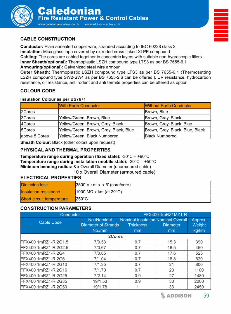
www.caledonian-cables.co.uk www.addison-cables.com
Caledonian
59ADDISON
fire Resistant Power & control cables
cable cOnsTRUcTiOn conductor: Plain annealed copper wire, stranded according to IEC 60228 class 2.insulation: Mica glass tape covered by extruded cross-linked XLPE compoundcabling: The cores are cabled together in concentric layers with suitable non-hygroscopic fillers.inner sheath(optional): Thermoplastic LSZH compound type LTS3 as per BS 7655-6.1 armouring(optional): Galvanized steel wire armourOuter sheath: Thermoplastic LSZH compound type LTS3 as per BS 7655-6.1 (Thermosetting LSZH compound type SW2-SW4 as per BS 7655-2.6 can be offered.). UV resistance, hydrocarbon resistance, oil resistance, anti rodent and anti termite properties can be offered as option.
cOlOUR cODe
insulation colour as per bs7671With Earth Conductor Without Earth Conductor
2Cores - Brown, Blue3Cores Yellow/Green, Brown, Blue Brown, Gray, Black4Cores Yellow/Green, Brown, Gray, Black Brown, Gray, Black, Blue5Cores Yellow/Green, Brown, Gray, Black, Blue Brown, Gray, Black, Blue, Blackabove 5 Cores Yellow/Green, Black Numbered Black Numberedsheath colour: Black (other colors upon request)
PHysical anD THeRMal PROPeRTiesTemperature range during operation (fixed state): -30°C – +90°C Temperature range during installation (mobile state): -20°C – +50°C Minimum bending radius: 8 x Overall Diameter (unarmoured cable) 10 x Overall Diameter (armoured cable)elecTRical PROPeRTiesDielectric test: 3500 V r.m.s. x 5’ (core/core)Insulation resistance 1000 MΩ x km (at 20°C)Short circuit temperature 250°C
cOnsTRUcTiOn PaRaMeTeRsConductor FFX400 1mRZ1MZ1-R
Cable Code No./Nominal Diameter of Strands
Nominal Insulation Thickness
Nominal Overall Diameter
Approx. Weight
No./mm mm mm kg/km2cores
FFX400 1mRZ1-R 2G1.5 7/0.53 0.7 15.3 390FFX400 1mRZ1-R 2G2.5 7/0.67 0.7 16.5 450FFX400 1mRZ1-R 2G4 7/0.85 0.7 17.6 525FFX400 1mRZ1-R 2G6 7/1.04 0.7 18.8 620FFX400 1mRZ1-R 2G10 7/1.35 0.7 21 800FFX400 1mRZ1-R 2G16 7/1.70 0.7 23 1100FFX400 1mRZ1-R 2G25 7/2.14 0.9 27 1480FFX400 1mRZ1-R 2G35 19/1.53 0.9 30 2000FFX400 1mRZ1-R 2G50 19/1.78 1 33 2450
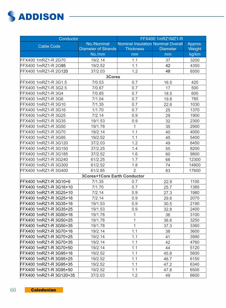
ADDISON
Caledonian60
Conductor FFX400 1mRZ1MZ1-R
Cable Code No./Nominal Diameter of Strands
Nominal Insulation Thickness
Nominal Overall Diameter
Approx. Weight
No./mm mm mm kg/kmFFX400 1mRZ1-R 2G70 19/2.14 1.1 37 3200FFX400 1mRZ1-R 2G95 19/2.52 1.1 42 4350FFX400 1mRZ1-R 2G120 37/2.03 1.2 48 6500
3coresFFX400 1mRZ1-R 3G1.5 7/0.53 0.7 16.5 420FFX400 1mRZ1-R 3G2.5 7/0.67 0.7 17 500FFX400 1mRZ1-R 3G4 7/0.85 0.7 18.5 600FFX400 1mRZ1-R 3G6 7/1.04 0.7 19.8 785FFX400 1mRZ1-R 3G10 7/1.35 0.7 22.6 1030FFX400 1mRZ1-R 3G16 1/1.70 0.7 25 1370FFX400 1mRZ1-R 3G25 7/2.14 0.9 29 1900FFX400 1mRZ1-R 3G35 19/1.53 0.9 32 2300FFX400 1mRZ1-R 3G50 19/1.78 1 35 2900FFX400 1mRZ1-R 3G70 19/2.14 1.1 40 4000FFX400 1mRZ1-R 3G95 19/2.52 1.1 45 5400FFX400 1mRZ1-R 3G120 37/2.03 1.2 49 6450FFX400 1mRZ1-R 3G150 37/2.25 1.4 55 8200FFX400 1mRZ1-R 3G185 37/2.52 1.6 60 9800FFX400 1mRZ1-R 3G240 61/2.25 1.7 68 12300FFX400 1mRZ1-R 3G300 61/2.52 1.8 74 14800FFX400 1mRZ1-R 3G400 61/2.85 2 83 17600
3cores+1core earth conductorFFX400 1mRZ1-R 3G10+6 7/1.35 0.7 22.9 1100FFX400 1mRZ1-R 3G16+10 7/1.70 0.7 25.7 1385FFX400 1mRZ1-R 3G25+10 7/2.14 0.9 27.3 1980FFX400 1mRZ1-R 3G25+16 7/2.14 0.9 29.8 2070FFX400 1mRZ1-R 3G35+16 19/1.53 0.9 30.5 2190FFX400 1mRZ1-R 3G35+25 19/1.53 0.9 32.8 2400FFX400 1mRZ1-R 3G50+16 19/1.78 1 36 3100FFX400 1mRZ1-R 3G50+25 19/1.78 1 36.6 3250FFX400 1mRZ1-R 3G50+35 19/1.78 1 37.3 3360FFX400 1mRZ1-R 3G70+16 19/2.14 1.1 38 3600FFX400 1mRZ1-R 3G70+25 19/2.14 1.1 41 3990FFX400 1mRZ1-R 3G70+35 19/2.14 1.1 42 4760FFX400 1mRZ1-R 3G70+50 19/2.14 1.1 44 5120FFX400 1mRZ1-R 3G95+16 19/2.52 1.1 45.8 5600FFX400 1mRZ1-R 3G95+25 19/2.52 1.1 46.7 6150FFX400 1mRZ1-R 3G95+35 19/2.52 1.1 47.2 6340FFX400 1mRZ1-R 3G95+50 19/2.52 1.1 47.8 6500FFX400 1mRZ1-R 3G120+35 37/2.03 1.2 49 6600

www.caledonian-cables.co.uk www.addison-cables.com
Caledonian
61ADDISON
fire Resistant Power & control cables
Conductor FFX400 1mRZ1MZ1-R
Cable Code No./Nominal Diameter of Strands
Nominal Insulation Thickness
Nominal Overall Diameter
Approx. Weight
No./mm mm mm kg/kmFFX400 1mRZ1-R 3G120+50 37/2.03 1.2 50.5 6990FFX400 1mRZ1-R 3G120+70 37/2.03 1.2 51 7200FFX400 1mRZ1-R 3G120+95 37/2.03 1.2 52.3 7600FFX400 1mRZ1-R 3G150+50 37/2.25 1.4 57 9000FFX400 1mRZ1-R 3G150+70 37/2.25 1.4 59 10600FFX400 1mRZ1-R 3G150+95 37/2.25 1.4 60 10900FFX400 1mRZ1-R 3G150+120 37/2.25 1.4 61 11100FFX400 1mRZ1-R 3G185+70 37/2.52 1.6 63 11650FFX400 1mRZ1-R 3G185+95 37/2.52 1.6 64 12000FFX400 1mRZ1-R 3G185+120 37/2.52 1.6 65 12300FFX400 1mRZ1-R 3G185+150 37/2.52 1.6 67 12700FFX400 1mRZ1-R 3G240+70 61/2.25 1.7 70 12900FFX400 1mRZ1-R 3G240+95 61/2.25 1.7 71 13500FFX400 1mRZ1-R 3G240+120 61/2.25 1.7 73 14000FFX400 1mRZ1-R 3G240+150 61/2.25 1.7 74 14700FFX400 1mRZ1-R 3G300+95 61/2.52 1.8 75 15600FFX400 1mRZ1-R 3G300+120 61/2.52 1.8 76 15720FFX400 1mRZ1-R 3G300+150 61/2.52 1.8 77 16000FFX400 1mRZ1-R 3G300+185 61/2.52 1.8 79 17560FFX400 1mRZ1-R 3G300+240 61/2.52 1.8 86 18900
4coresFFX400 1mRZ1-R 4G1.5 7/0.53 0.7 16 475FFX400 1mRZ1-R 4G2.5 7/0.67 0.7 17.8 570FFX400 1mRZ1-R 4G4 7/0.85 0.7 19.8 690FFX400 1mRZ1-R 4G6 7/1.04 0.7 21 940FFX400 1mRZ1-R 4G10 7/1.35 0.7 23.3 1200FFX400 1mRZ1-R 4G16 1/1.70 0.7 26.5 1400FFX400 1mRZ1-R 4G25 7/2.14 0.9 30.5 2400FFX400 1mRZ1-R 4G35 19/1.53 0.9 34 2800FFX400 1mRZ1-R 4G50 19/1.78 1 38 3500FFX400 1mRZ1-R 4G70 19/2.14 1.1 44 5300FFX400 1mRZ1-R 4G95 19/2.52 1.1 48.5 6700FFX400 1mRZ1-R 4G120 37/2.03 1.2 54 8500FFX400 1mRZ1-R 4G150 37/2.25 1.4 59 10000FFX400 1mRZ1-R 4G185 37/2.52 1.6 64.5 12200FFX400 1mRZ1-R 4G240 61/2.25 1.7 74 15400FFX400 1mRZ1-R 4G300 61/2.52 1.8 82 19500FFX400 1mRZ1-R 4G400 61/2.85 2 92 25500
4cores+1core earth conductor

ADDISON
Caledonian62
Conductor FFX400 1mRZ1MZ1-R
Cable Code No./Nominal Diameter of Strands
Nominal Insulation Thickness
Nominal Overall Diameter
Approx. Weight
No./mm mm mm kg/kmFFX400 1mRZ1-R 4G10+6 7/1.35 0.7 24 1300FFX400 1mRZ1-R 4G16+10 7/1.70 0.7 26 1600FFX400 1mRZ1-R 4G25+10 7/2.14 0.7 29 2015FFX400 1mRZ1-R 4G25+16 7/2.14 0.7 32 2540FFX400 1mRZ1-R 4G35+16 19/1.53 0.9 35 3000FFX400 1mRZ1-R 4G35+25 19/1.53 0.9 35.6 3170FFX400 1mRZ1-R 4G50+16 19/1.78 1 40 3800FFX400 1mRZ1-R 4G50+25 19/1.78 1 41.4 4100FFX400 1mRZ1-R 4G50+35 19/1.78 1 42.9 4350FFX400 1mRZ1-R 4G70+16 19/2.14 1.1 45 6270FFX400 1mRZ1-R 4G70+25 19/2.14 1.1 47 6900FFX400 1mRZ1-R 4G70+35 19/2.14 1.1 48 7200FFX400 1mRZ1-R 4G70+50 19/2.14 1.1 50 7600FFX400 1mRZ1-R 4G95+16 19/2.52 1.1 51 8000FFX400 1mRZ1-R 4G95+25 19/2.52 1.1 52 8100FFX400 1mRZ1-R 4G95+35 19/2.52 1.1 53 8250FFX400 1mRZ1-R 4G95+50 19/2.52 1.1 54 8390FFX400 1mRZ1-R 4G120+35 37/2.03 1.2 54 8600FFX400 1mRZ1-R 4G120+50 37/2.03 1.2 55 8800FFX400 1mRZ1-R 4G120+70 37/2.03 1.2 56 9100FFX400 1mRZ1-R 4G120+95 37/2.03 1.2 57 9400FFX400 1mRZ1-R 4G150+50 37/2.25 1.4 61 10800FFX400 1mRZ1-R 4G150+70 37/2.25 1.4 62 11100FFX400 1mRZ1-R 4G150+95 37/2.25 1.4 64 11500FFX400 1mRZ1-R 4G150+120 37/2.25 1.4 65 11900FFX400 1mRZ1-R 4G185+70 37/2.52 1.6 66 12900FFX400 1mRZ1-R 4G185+95 37/2.52 1.6 68 13600FFX400 1mRZ1-R 4G185+120 37/2.52 1.6 70 14700FFX400 1mRZ1-R 4G185+150 37/2.52 1.6 73 15500FFX400 1mRZ1-R 4G240+70 61/2.25 1.7 76 16000FFX400 1mRZ1-R 4G240+95 61/2.25 1.7 77 16900FFX400 1mRZ1-R 4G240+120 61/2.25 1.7 78 17600FFX400 1mRZ1-R 4G240+150 61/2.25 1.7 79 18200FFX400 1mRZ1-R 4G300+95 61/2.52 1.8 81 19700FFX400 1mRZ1-R 4G300+120 61/2.52 1.8 82 20700FFX400 1mRZ1-R 4G300+150 61/2.52 1.8 84 21060FFX400 1mRZ1-R 4G300+185 61/2.52 1.8 85 22170FFX400 1mRZ1-R 4G300+240 61/2.52 1.8 87 24500
5coresFFX400 1mRZ1-R 5G1.5 7/0.53 0.7 18.8 558 FFX400 1mRZ1-R 5G2.5 7/0.67 0.7 20.9 670
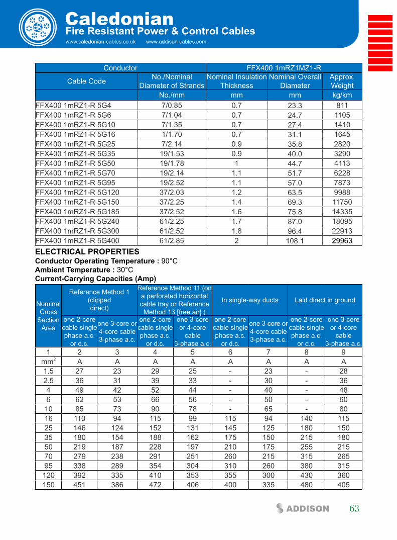
www.caledonian-cables.co.uk www.addison-cables.com
Caledonian
63ADDISON
fire Resistant Power & control cables
Conductor FFX400 1mRZ1MZ1-R
Cable Code No./Nominal Diameter of Strands
Nominal Insulation Thickness
Nominal Overall Diameter
Approx. Weight
No./mm mm mm kg/kmFFX400 1mRZ1-R 5G4 7/0.85 0.7 23.3 811 FFX400 1mRZ1-R 5G6 7/1.04 0.7 24.7 1105 FFX400 1mRZ1-R 5G10 7/1.35 0.7 27.4 1410 FFX400 1mRZ1-R 5G16 1/1.70 0.7 31.1 1645 FFX400 1mRZ1-R 5G25 7/2.14 0.9 35.8 2820 FFX400 1mRZ1-R 5G35 19/1.53 0.9 40.0 3290 FFX400 1mRZ1-R 5G50 19/1.78 1 44.7 4113 FFX400 1mRZ1-R 5G70 19/2.14 1.1 51.7 6228 FFX400 1mRZ1-R 5G95 19/2.52 1.1 57.0 7873 FFX400 1mRZ1-R 5G120 37/2.03 1.2 63.5 9988 FFX400 1mRZ1-R 5G150 37/2.25 1.4 69.3 11750 FFX400 1mRZ1-R 5G185 37/2.52 1.6 75.8 14335 FFX400 1mRZ1-R 5G240 61/2.25 1.7 87.0 18095 FFX400 1mRZ1-R 5G300 61/2.52 1.8 96.4 22913 FFX400 1mRZ1-R 5G400 61/2.85 2 108.1 29963 elecTRical PROPeRTies conductor Operating Temperature : 90°C ambient Temperature : 30°C current-carrying capacities (amp)
Nominal Cross
Section Area
Reference Method 1 (clippeddirect)
Reference Method 11 (on a perforated horizontal cable tray or Reference Method 13 [free air] )
In single-way ducts Laid direct in ground
one 2-core cable single phase a.c.
or d.c.
one 3-core or 4-core cable 3-phase a.c.
one 2-core cable single phase a.c.
or d.c.
one 3-core or 4-core
cable 3-phase a.c.
one 2-core cable single phase a.c.
or d.c.
one 3-core or 4-core cable 3-phase a.c.
one 2-core cable single phase a.c.
or d.c.
one 3-core or 4-core
cable 3-phase a.c.
1 2 3 4 5 6 7 8 9mm2 A A A A A A A A1.5 27 23 29 25 - 23 - 282.5 36 31 39 33 - 30 - 364 49 42 52 44 - 40 - 486 62 53 66 56 - 50 - 6010 85 73 90 78 - 65 - 8016 110 94 115 99 115 94 140 11525 146 124 152 131 145 125 180 15035 180 154 188 162 175 150 215 18050 219 187 228 197 210 175 255 21570 279 238 291 251 260 215 315 26595 338 289 354 304 310 260 380 315120 392 335 410 353 355 300 430 360150 451 386 472 406 400 335 480 405

ADDISON
Caledonian64
185 515 441 539 463 455 380 540 460240 607 520 636 546 520 440 630 530300 698 599 732 628 590 495 700 590400 787 673 847 728 660 560 790 670
Voltage Drop (Per amp Per Meter)Nominal Cross
Section Area
2-core cable d.c.
2 cables, single-phase a.c.
3 or 4 cables, 3-phase a.c.
2 cables,single-phase
a.c.
3 or 4 cables,3-phase a.c.
In ducts orin ground
In ducts orin ground
1 2 3 4 5 6mm2 mV/A/m mV/A/m mV/A/m mV/A/m mV/A/m1.5 31 31 27 31 252.5 19 19 16 19 154 12 12 10 12 9.76 7.9 7.9 6.8 7.9 6.510 4.7 4.7 4 4.7 3.916 2.9 2.9 2.5 2.9 2.6 r x z r x z
25 1.85 1.35 0.16 1.9 1.6 0.14 1.65 1.9 1.635 1.35 1.35 0.155 1.35 1.15 0.135 1.15 1.35 1.250 0.98 0.99 0.155 1 0.86 0.135 0.87 1 0.8770 0.67 0.67 0.15 0.69 0.59 0.13 0.6 0.69 0.6195 0.49 0.5 0.15 0.52 0.43 0.13 0.45 0.52 0.45120 0.39 0.4 0.145 0.42 0.34 0.13 0.37 0.42 0.36150 0.31 0.32 0.145 0.35 0.28 0.125 0.3 0.35 0.3185 0.25 0.26 0.145 0.29 0.22 0.125 0.26 0.29 0.25240 0.195 0.2 0.14 0.24 0.175 0.125 0.21 0.24 0.21300 0.155 0.16 0.14 0.21 0.14 0.12 0.185 0.21 0.19400 0.12 0.13 0.14 0.19 0.115 0.12 0.165 0.19 0.18
Note : r = conductor resistance at operating temperature x = reactance z = impedance
Rated Voltage
600/1000V
NStandard
BS 7846IEC 60502-1
Circuit IntegrityIEC 60331/BS 6387
NF C32-070-2.3(CR1)
W E
Reduced Fire PropagationNF C32-070-2.2(C1)
IEC60332-3-24/EN50266-2-4
Flame RetardancyNF C32-070-2.1(C2)
IEC60332-1-2/EN50265-2-1
Low ToxicityNES 02-713/NF C 20-454
Low CorrosivityIEC60754-2
EN50267-2-2/3NF C 32-074
Low Smoke EmissionIEC 61034-1&2
EN 50268-1&2/NF C32-073
Zero
Halogen FreeIEC60754-1
EN50267-2-1
W E
DIN 4102-12Functional Integrity

www.caledonian-cables.co.uk www.addison-cables.com
Caledonian
65ADDISON
fire Resistant Power & control cables
300/500V sR insulated control cables (2-4 cores) FFX200 05SZ1-U (PH60) (CU/SR/LSZH 300/500V Class 1)
LSZH Outer Sheath
Silicone Rubber Insulation
Plain Annealed Copper
aPPlicaTiOn
The cables are designed, for use as control cable for emergency services and fire circuit control.
sTanDaRDs
Basic design adapted from BS 7629-1
fiRe PeRfORMance
Circuit IntegrityIEC 60331-21; BS 6387 CWZ; DIN VDE 0472-814(FE180); BS 8434-1 (30mins); BS 5839-1 Clause 26 2d; CEI 20-36/2-1; SS299-1; NBN C 30-004 (cat. F3); NF C32-070-2.3(CR1)
Circuit Integrity with mechanical shock EN 50200(PH60); CEI 20-36/4-0
Circuit Integrity with mechanical shock & water spray EN 50200 annex E
System Circuit Integrity DIN 4102-12, E30 depending on lay system
Flame Retardance (Single Vertical Wire Test)
EN 60332-1-2; IEC 60332-1-2; BS EN 60332-1-2;VDE 0482-332-1 ; NBN C 30-004 (cat. F1); NF C32-070-2.1(C2); CEI 20-35/1-2; EN 50265-2-1*; DIN VDE 0482-265-2-1*
Reduced Fire Propagation (Vertically-mounted bundled wires & cable test)
EN 60332-3-24 (cat. C); IEC 60332-3-24; BS EN 60332-3-24; VDE 0482-332-3; NBN C 30-004 (cat. F2); NF C32-070-2.2(C1); CEI 20-22/3-4; EN 50266-2-4*; DIN VDE 0482-266-2-4
Halogen Free IEC 60754-1; EN 50267-2-1; DIN VDE 0482-267-2-1; CEI 20-37/2-1 ; BS 6425-1*
No Corrosive Gas Emission IEC 60754-2; EN 50267-2-2; DIN VDE 0482-267-2-2; CEI 20-37/2-2 ; BS 6425-2*
Minimum Smoke Emission IEC 61034-1&2; EN 61034 -1&2; DIN VDE 0482-1034-1&2; CEI 20-37/3-1&2; EN 50268-1&2*; BS 7622-1&2*
No Toxic gases NES 02-713; NF C 20-454note: asterisk * denotes superseded standard.

ADDISON
Caledonian66
VOlTaGe RaTinG
300/500 V
cable cOnsTRUcTiOn
conductors: Plain annealed copper wire, solid according to IEC 60228 class 1.insulation: Fire resistant silicone rubber compound type EI2 as per BS 7655-1.1.cabling: The cores are cabled together in concentric layers with suitable non-hygroscopic fillers.Outer sheath: Thermoplastic LSZH compound type LTS3 as per BS 7655-6.1 (Thermosetting LSZH compound type SW2-SW4 as per BS 7655-2.6 can be offered.). UV resistance, hydrocarbon resistance, oil resistance, anti rodent and anti termite properties can be offered as option.
cOlOUR cODeinsulation colour as per bs7671
Without Earth Conductor2Cores Brown, Blue3Cores Brown, Gray, Black4Cores Brown, Gray, Black, Bluesheath colour: Orange (other colors upon request)
PHysical anD THeRMal PROPeRTies
Temperature range during operation (fixed state): -30°C – +90°C Temperature range during installation (mobile state): -20°C – +50°C Minimum bending radius: 6 x Overall Diameter
elecTRical PROPeRTies
Dielectric test: 2000 V r.m.s. x 5’ (core/core)
Insulation resistance ≥300 MΩ x km (at 20°C)
Short circuit temperature 350°C
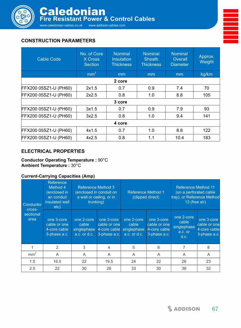
www.caledonian-cables.co.uk www.addison-cables.com
Caledonian
67ADDISON
fire Resistant Power & control cables
cOnsTRUcTiOn PaRaMeTeRs
Cable CodeNo. of Core
X Cross Section
NominalInsulationThickness
NominalSheath
Thickness
Nominal Overall
Diameter
Approx.Weight
mm2 mm mm mm kg/km2 core
FFX200 05SZ1-U (PH60) 2x1.5 0.7 0.9 7.4 70FFX200 05SZ1-U (PH60) 2x2.5 0.8 1.0 8.8 105
3 coreFFX200 05SZ1-U (PH60) 3x1.5 0.7 0.9 7.9 93FFX200 05SZ1-U (PH60) 3x2.5 0.8 1.0 9.4 141
4 core FFX200 05SZ1-U (PH60) 4x1.5 0.7 1.0 8.8 122FFX200 05SZ1-U (PH60) 4x2.5 0.8 1.1 10.4 183
elecTRical PROPeRTies
conductor Operating Temperature : 90°C ambient Temperature : 30°C current-carrying capacities (amp)
Conductor cross-
sectional area
Reference Method 4
(enclosed in an conduit
insulated wall etc)
Reference Method 3(enclosed in conduit on a wall or ceiling, or in
trunking)
Reference Method 1 (clipped direct)
Reference Method 11(on a perforated cable
tray), or Reference Method 13 (free air)
one 3-core cable or one 4-core cable 3-phase a.c.
one 2-core cable
singlephase a.c. or d.c.
one 3-core cable or one 4-core cable 3-phase a.c.
one 2-core cable
singlephase a.c. or d.c.
one 3-core cable or one 4-core cable 3-phase a.c.
one 2-corecable
singlephasea.c. or
d.c.
one 3-corecable or one4-core cable3-phase a.c.
1 2 3 4 5 6 7 8
mm2 A A A A A A A
1.5 16.5 22 19.5 24 22 26 23
2.5 22 30 26 33 30 36 32

ADDISON
Caledonian68
Voltage Drop (Per amp Per Meter)
Nominal CrossSection Area 2-core cable d.c. 2 cables, single-phase
a.c.3 or 4 cables, 3-phase
a.c.
1 2 3 4mm2 mV/A/m mV/A/m mV/A/m1.5 31 31 272.5 19 19 16
Rated Voltage
300/500V
NStandard
BS 7629-1
Circuit IntegrityIEC 60331/BS 6387
EN 50200NF C32-070-2.3(CR1)
W E
Reduced Fire PropagationNF C32-070-2.2(C1)
IEC60332-3-24/EN50266-2-4
Flame RetardancyNF C32-070-2.1(C2)
IEC60332-1-2/EN50265-2-1
Low ToxicityNES 02-713/NF C 20-454
Low CorrosivityIEC60754-2
EN50267-2-2/3NF C 32-074
Low Smoke EmissionIEC 61034-1&2
EN 50268-1&2/NF C32-073
Zero
Halogen FreeIEC60754-1
EN50267-2-1
W E
DIN 4102-12Functional Integrity

www.caledonian-cables.co.uk www.addison-cables.com
Caledonian
69ADDISON
fire Resistant Power & control cables
300/500V sR insulated & Overall screened control cables (2-4 cores & Multicore)
FFX200 05SOZ1-U (PH30/60) (CU/SR/OSCR/LSZH 300/500V Class 1) FFX200 05SOZ1-R (PH30/60) (CU/SR/OSCR/LSZH 300/500V Class 2)
Solid Copper Conductor
Silicone Rubber Insulation
LSZH Sheath
Aluminum/Polyester Tape with Tinned Copper Drain Wire
aPPlicaTiOnThe cables are primarily intended for use in the following applications:
BS 5266-1 for emergency lighting of premises BS 5839-1 for fire detection and fire alarm systems in and around building BS 5839-8 for voice alarm systems BS 5839-9 for emergency voice communication systems.
sTanDaRDs
Basic design to BS7629-1
fiRe PeRfORMance
Circuit IntegrityIEC 60331-21; BS 6387 CWZ; DIN VDE 0472-814(FE180); BS 8434-1 (30mins); BS 5839-1 Clause 26 2d; CEI 20-36/2-1; SS299-1; NBN C 30-004 (cat. F3); NF C32-070-2.3(CR1)
Circuit Integrity with mechanical shock EN 50200(PH30/60); CEI 20-36/4-0
Circuit Integrity with mechanical shock & water spray EN 50200 annex E
System Circuit Integrity DIN 4102-12, E30 depending on lay system
Flame Retardance (Single Vertical Wire Test)
EN 60332-1-2; IEC 60332-1-2; BS EN 60332-1-2; VDE 0482-332-1 ; NBN C 30-004 (cat. F1); NF C32-070-2.1(C2); CEI 20-35/1-2; EN 50265-2-1*; DIN VDE 0482-265-2-1*
Reduced Fire Propagation (Vertically-mounted bundled wires & cable test)
EN 60332-3-24 (cat. C); IEC 60332-3-24; BS EN 60332-3-24; VDE 0482-332-3; NBN C 30-004 (cat. F2); NF C32-070-2.2(C1); CEI 20-22/3-4; EN 50266-2-4*; DIN VDE 0482-266-2-4
Halogen Free IEC 60754-1; EN 50267-2-1; DIN VDE 0482-267-2-1; CEI 20-37/2-1 ; BS 6425-1*
No Corrosive Gas Emission IEC 60754-2; EN 50267-2-2; DIN VDE 0482-267-2-2; CEI 20-37/2-2 ; BS 6425-2*

ADDISON
Caledonian70
Minimum Smoke Emission IEC 61034-1&2; EN 61034 -1&2; DIN VDE 0482-1034-1&2; CEI 20-37/3-1&2; EN 50268-1&2*; BS 7622-1&2*
No Toxic gases NES 02-713; NF C 20-454note: asterisk * denotes superseded standard.
VOlTaGe RaTinG
300/500 V
cable cOnsTRUcTiOn
conductors: Plain annealed copper wire, solid according to IEC 60228 class 1, stranded according to IEC 60228 class 2.insulation: Fire resistant silicone rubber compound type EI2 as per BS 7655-1.1.cabling: The cores are cabled together in concentric layers with suitable non-hygroscopic fillers.Overall screen: Aluminum/polyester tape with tinned copper drain wire.circuit Protective conductor or Drain Wire: Uninsulated tinned copper conductor of the same section and class as the insulated conductors in the 2-, 3-and 4-core cables. Drain wire of 0.5mm2 tinned copper conductor is provided in cables of more than 4 conductors. Outer sheath: Thermoplastic LSZH compound type LTS3 as per BS 7655-6.1 (Thermosetting LSZH compound type SW2-SW4 as per BS 7655-2.6 can be offered.). UV resistance, hydrocarbon resistance, oil resistance, anti rodent and anti termite properties can be offered as option.
cOlOUR cODe
insulation colour:Without Earth Conductor
2Cores Brown, Blue3Cores Brown, Gray, Black4Cores Brown, Gray, Black, Blue7Cores Centre: Brown, 1st layer: Brown -Black -4 Cores White 12Cores Centre: Brown, Black -White 1st layer: Brown -Black -7 Cores White
19Cores Centre: Brown , 1st layer: Brown -Black -4 Cores White 2nd layer: Brown -black -10 Cores White
sheath colour: Orange (other colors upon request)
PHysical anD THeRMal PROPeRTies
Temperature range during operation (fixed state): -30°C – +90°CTemperature range during installation (mobile state): -20°C – +50°C Minimum bending radius: 6 x Overall Diameter
elecTRical PROPeRTies
Dielectric test: 2000 V r.m.s. x 5’ (core/core)
Insulation resistance ≥300 MΩ x km (at 20°C)Short circuit temperature 350°C
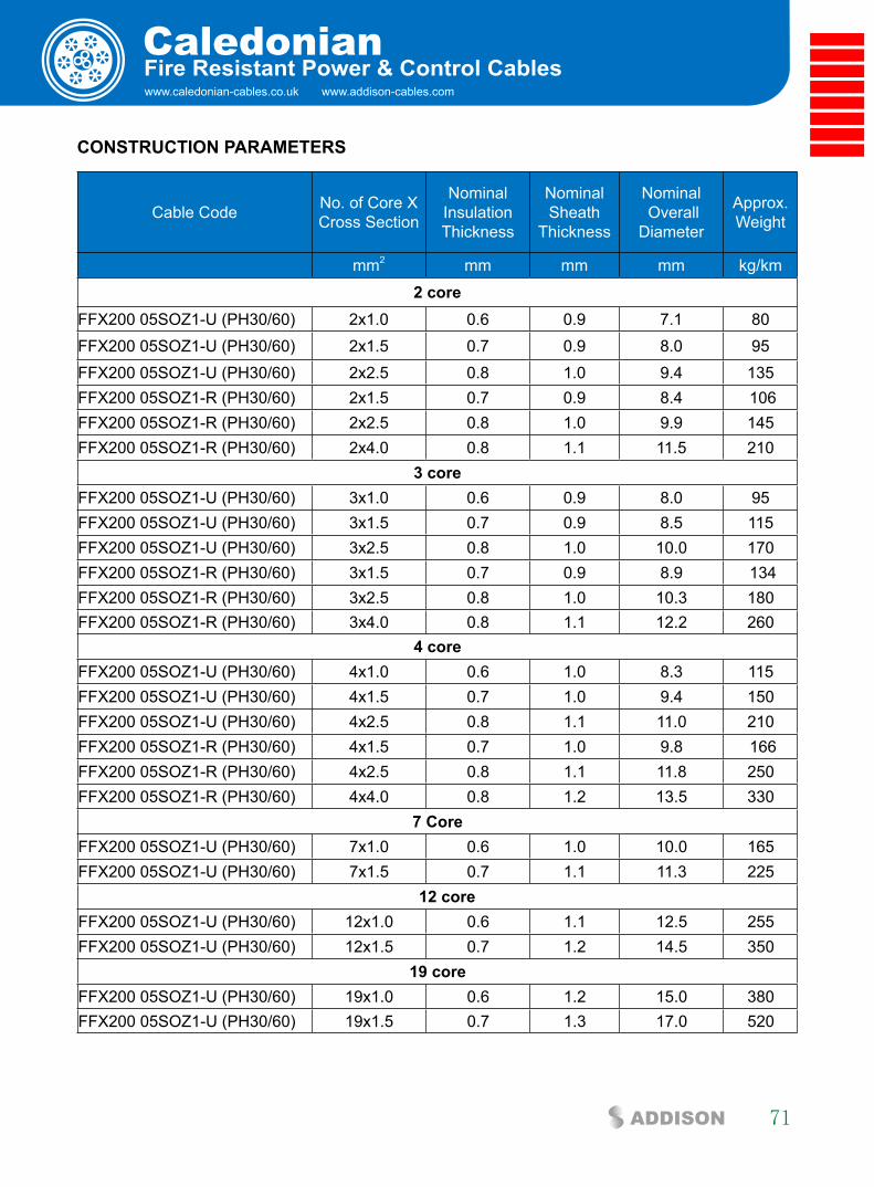
www.caledonian-cables.co.uk www.addison-cables.com
Caledonian
71ADDISON
fire Resistant Power & control cables
cOnsTRUcTiOn PaRaMeTeRs
Cable Code No. of Core X Cross Section
NominalInsulationThickness
NominalSheath
Thickness
Nominal Overall
Diameter
Approx.Weight
mm2 mm mm mm kg/km
2 core FFX200 05SOZ1-U (PH30/60) 2x1.0 0.6 0.9 7.1 80 FFX200 05SOZ1-U (PH30/60) 2x1.5 0.7 0.9 8.0 95 FFX200 05SOZ1-U (PH30/60) 2x2.5 0.8 1.0 9.4 135 FFX200 05SOZ1-R (PH30/60) 2x1.5 0.7 0.9 8.4 106FFX200 05SOZ1-R (PH30/60) 2x2.5 0.8 1.0 9.9 145 FFX200 05SOZ1-R (PH30/60) 2x4.0 0.8 1.1 11.5 210
3 coreFFX200 05SOZ1-U (PH30/60) 3x1.0 0.6 0.9 8.0 95FFX200 05SOZ1-U (PH30/60) 3x1.5 0.7 0.9 8.5 115 FFX200 05SOZ1-U (PH30/60) 3x2.5 0.8 1.0 10.0 170 FFX200 05SOZ1-R (PH30/60) 3x1.5 0.7 0.9 8.9 134 FFX200 05SOZ1-R (PH30/60) 3x2.5 0.8 1.0 10.3 180FFX200 05SOZ1-R (PH30/60) 3x4.0 0.8 1.1 12.2 260
4 coreFFX200 05SOZ1-U (PH30/60) 4x1.0 0.6 1.0 8.3 115FFX200 05SOZ1-U (PH30/60) 4x1.5 0.7 1.0 9.4 150 FFX200 05SOZ1-U (PH30/60) 4x2.5 0.8 1.1 11.0 210FFX200 05SOZ1-R (PH30/60) 4x1.5 0.7 1.0 9.8 166 FFX200 05SOZ1-R (PH30/60) 4x2.5 0.8 1.1 11.8 250 FFX200 05SOZ1-R (PH30/60) 4x4.0 0.8 1.2 13.5 330
7 coreFFX200 05SOZ1-U (PH30/60) 7x1.0 0.6 1.0 10.0 165 FFX200 05SOZ1-U (PH30/60) 7x1.5 0.7 1.1 11.3 225 12 coreFFX200 05SOZ1-U (PH30/60) 12x1.0 0.6 1.1 12.5 255 FFX200 05SOZ1-U (PH30/60) 12x1.5 0.7 1.2 14.5 350
19 coreFFX200 05SOZ1-U (PH30/60) 19x1.0 0.6 1.2 15.0 380 FFX200 05SOZ1-U (PH30/60) 19x1.5 0.7 1.3 17.0 520
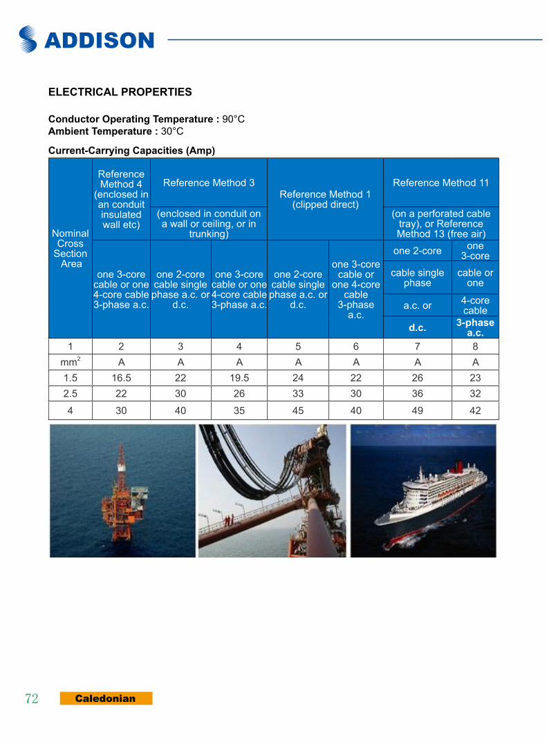
ADDISON
Caledonian72
elecTRical PROPeRTies
conductor Operating Temperature : 90°C ambient Temperature : 30°C
current-carrying capacities (amp)
Nominal Cross
Section Area
Reference Method 4
(enclosed in an conduit insulated wall etc)
Reference Method 3Reference Method 1
(clipped direct)
Reference Method 11
(enclosed in conduit on a wall or ceiling, or in
trunking)
(on a perforated cable tray), or Reference Method 13 (free air)
one 3-core cable or one 4-core cable 3-phase a.c.
one 2-core cable singlephase a.c. or
d.c.
one 3-core cable or one 4-core cable 3-phase a.c.
one 2-core cable singlephase a.c. or
d.c.
one 3-core cable or
one 4-core cable
3-phase a.c.
one 2-core one 3-core
cable single phase
cable or one
a.c. or 4-core cable
d.c. 3-phase a.c.
1 2 3 4 5 6 7 8mm2 A A A A A A A1.5 16.5 22 19.5 24 22 26 232.5 22 30 26 33 30 36 32
4 30 40 35 45 40 49 42

www.caledonian-cables.co.uk www.addison-cables.com
Caledonian
73ADDISON
fire Resistant Power & control cables
Voltage Drop (Per amp Per Meter)
Nominal CrossSection Area 2-core cable d.c. 2-core cable single-
phase a.c3-core or 4-core cable
3-phase a.c.
1 2 3 4mm2 mV/A/m mV/A/m mV/A/m1.5 31 31 272.5 19 19 164 12 12 10
Rated Voltage
300/500V
NStandard
BS 7629-1
Circuit IntegrityIEC 60331/BS 6387
EN 50200NF C32-070-2.3(CR1)
W E
Reduced Fire PropagationNF C32-070-2.2(C1)
IEC60332-3-24/EN50266-2-4
Flame RetardancyNF C32-070-2.1(C2)
IEC60332-1-2/EN50265-2-1
Low ToxicityNES 02-713/NF C 20-454
Low CorrosivityIEC60754-2
EN50267-2-2/3NF C 32-074
Low Smoke EmissionIEC 61034-1&2
EN 50268-1&2/NF C32-073
Zero
Halogen FreeIEC60754-1
EN50267-2-1
W E
DIN 4102-12Functional Integrity
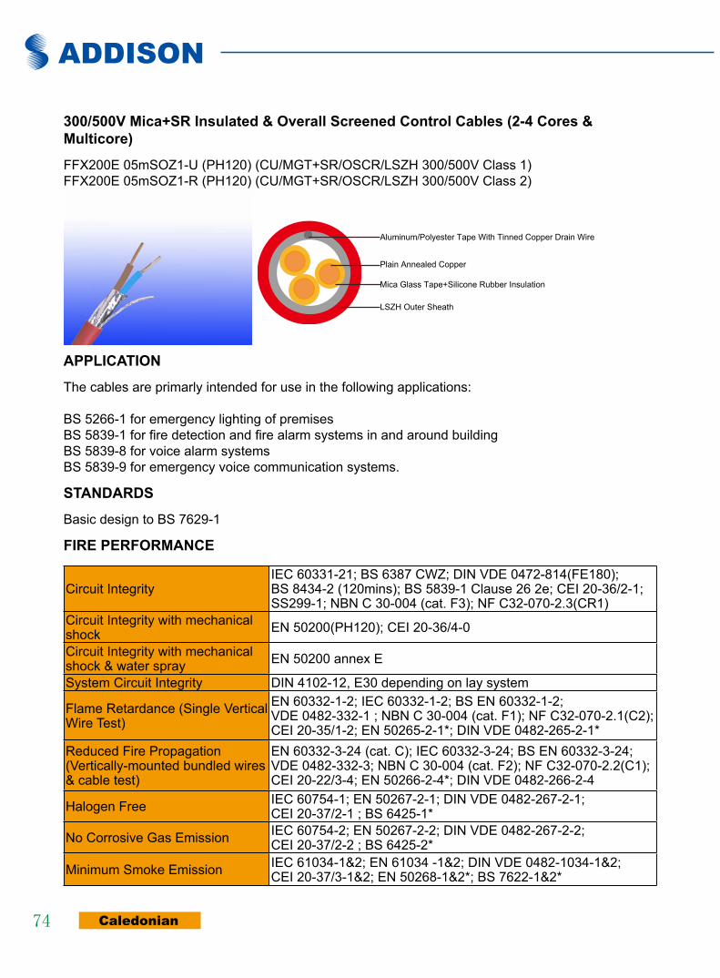
ADDISON
Caledonian74
300/500V Mica+sR insulated & Overall screened control cables (2-4 cores & Multicore)
FFX200E 05mSOZ1-U (PH120) (CU/MGT+SR/OSCR/LSZH 300/500V Class 1) FFX200E 05mSOZ1-R (PH120) (CU/MGT+SR/OSCR/LSZH 300/500V Class 2)
Mica Glass Tape+Silicone Rubber Insulation
Plain Annealed Copper
Aluminum/Polyester Tape With Tinned Copper Drain Wire
LSZH Outer Sheath
aPPlicaTiOn
The cables are primarly intended for use in the following applications:
BS 5266-1 for emergency lighting of premisesBS 5839-1 for fire detection and fire alarm systems in and around buildingBS 5839-8 for voice alarm systemsBS 5839-9 for emergency voice communication systems.
sTanDaRDs
Basic design to BS 7629-1
fiRe PeRfORMance
Circuit IntegrityIEC 60331-21; BS 6387 CWZ; DIN VDE 0472-814(FE180); BS 8434-2 (120mins); BS 5839-1 Clause 26 2e; CEI 20-36/2-1; SS299-1; NBN C 30-004 (cat. F3); NF C32-070-2.3(CR1)
Circuit Integrity with mechanical shock EN 50200(PH120); CEI 20-36/4-0
Circuit Integrity with mechanical shock & water spray EN 50200 annex E
System Circuit Integrity DIN 4102-12, E30 depending on lay system
Flame Retardance (Single Vertical Wire Test)
EN 60332-1-2; IEC 60332-1-2; BS EN 60332-1-2; VDE 0482-332-1 ; NBN C 30-004 (cat. F1); NF C32-070-2.1(C2); CEI 20-35/1-2; EN 50265-2-1*; DIN VDE 0482-265-2-1*
Reduced Fire Propagation (Vertically-mounted bundled wires & cable test)
EN 60332-3-24 (cat. C); IEC 60332-3-24; BS EN 60332-3-24; VDE 0482-332-3; NBN C 30-004 (cat. F2); NF C32-070-2.2(C1); CEI 20-22/3-4; EN 50266-2-4*; DIN VDE 0482-266-2-4
Halogen Free IEC 60754-1; EN 50267-2-1; DIN VDE 0482-267-2-1; CEI 20-37/2-1 ; BS 6425-1*
No Corrosive Gas Emission IEC 60754-2; EN 50267-2-2; DIN VDE 0482-267-2-2; CEI 20-37/2-2 ; BS 6425-2*
Minimum Smoke Emission IEC 61034-1&2; EN 61034 -1&2; DIN VDE 0482-1034-1&2; CEI 20-37/3-1&2; EN 50268-1&2*; BS 7622-1&2*

www.caledonian-cables.co.uk www.addison-cables.com
Caledonian
75ADDISON
fire Resistant Power & control cables
No Toxic gases NES 02-713; NF C 20-454note: asterisk * denotes superseded standard.
VOlTaGe RaTinG
300/500 V
cable cOnsTRUcTiOn conductors: Plain annealed copper wire, solid according to IEC 60228 class 1, stranded according to IEC 60228 class 2. insulation: Mica glass fire resistant tape covered by fire resistant silicone rubber compound type EI2 as per BS 7655-1.1.cabling: The cores are cabled together in concentric layers with suitable non-hygroscopic fillers.Overall screen: Aluminum/polyester tape with tinned copper drain wire. circuit Protective conductor: Uninsulated tinned copper conductor of the same section and class as the insulated conductors in the 2-, 3- and 4-core cables. Drain wire of 0.5mm2 tinned copper conductor is provided in cables of more than 4 conductors.Outer sheath: Thermoplastic LSZH compound type LTS3 as per BS 7655-6.1 (Thermosetting LSZH compound type SW2-SW4 as per BS 7655-2.6 can be offered.). UV resistance, hydrocarbon resistance, oil resistance, anti rodent and anti termite properties can be offered as option.
cOlOUR cODe insulation colour:
Without Earth Conductor2Cores Brown, Blue3Cores Brown, Gray, Black4Cores Brown, Gray, Black, Blue7Cores Centre: Brown, 1st layer: Brown -Black -4 Cores White 12Cores Centre: Brown, Black -White 1st layer: Brown -Black -7 Cores White
19Cores Centre: Brown , 1st layer: Brown -Black -4 Cores White 2nd layer: Brown -black -10 Cores White
sheath colour: Colour red or white (other colours on request)
PHysical anD THeRMal PROPeRTiesTemperature range during operation (fixed state): -30°C – +90°CTemperature range during installation (mobile state): -20°C – +50°CMinimum bending radius: 7.5 x Overall Diameter
elecTRical PROPeRTies
Dielectric test: 2000 V r.m.s. x 5’ (core/core)Insulation resistance ≥300 MΩ x km (at 20°C)Short circuit temperature 350°C
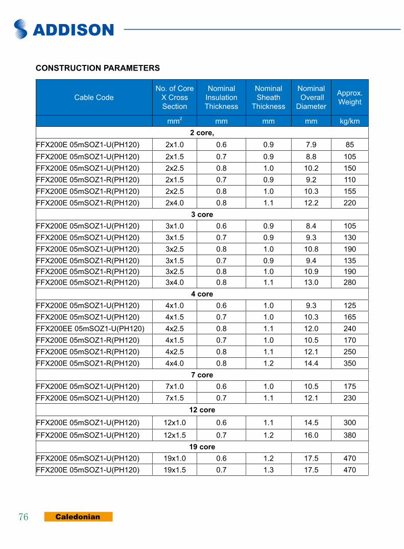
ADDISON
Caledonian76
cOnsTRUcTiOn PaRaMeTeRs
Cable CodeNo. of Core
X Cross Section
NominalInsulationThickness
NominalSheath
Thickness
Nominal Overall
Diameter
Approx.Weight
mm2 mm mm mm kg/km2 core,
FFX200E 05mSOZ1-U(PH120) 2x1.0 0.6 0.9 7.9 85FFX200E 05mSOZ1-U(PH120) 2x1.5 0.7 0.9 8.8 105FFX200E 05mSOZ1-U(PH120) 2x2.5 0.8 1.0 10.2 150FFX200E 05mSOZ1-R(PH120) 2x1.5 0.7 0.9 9.2 110FFX200E 05mSOZ1-R(PH120) 2x2.5 0.8 1.0 10.3 155FFX200E 05mSOZ1-R(PH120) 2x4.0 0.8 1.1 12.2 220
3 coreFFX200E 05mSOZ1-U(PH120) 3x1.0 0.6 0.9 8.4 105FFX200E 05mSOZ1-U(PH120) 3x1.5 0.7 0.9 9.3 130FFX200E 05mSOZ1-U(PH120) 3x2.5 0.8 1.0 10.8 190FFX200E 05mSOZ1-R(PH120) 3x1.5 0.7 0.9 9.4 135FFX200E 05mSOZ1-R(PH120) 3x2.5 0.8 1.0 10.9 190FFX200E 05mSOZ1-R(PH120) 3x4.0 0.8 1.1 13.0 280
4 coreFFX200E 05mSOZ1-U(PH120) 4x1.0 0.6 1.0 9.3 125FFX200E 05mSOZ1-U(PH120) 4x1.5 0.7 1.0 10.3 165FFX200EE 05mSOZ1-U(PH120) 4x2.5 0.8 1.1 12.0 240FFX200E 05mSOZ1-R(PH120) 4x1.5 0.7 1.0 10.5 170FFX200E 05mSOZ1-R(PH120) 4x2.5 0.8 1.1 12.1 250FFX200E 05mSOZ1-R(PH120) 4x4.0 0.8 1.2 14.4 350
7 coreFFX200E 05mSOZ1-U(PH120) 7x1.0 0.6 1.0 10.5 175FFX200E 05mSOZ1-U(PH120) 7x1.5 0.7 1.1 12.1 230
12 coreFFX200E 05mSOZ1-U(PH120) 12x1.0 0.6 1.1 14.5 300
FFX200E 05mSOZ1-U(PH120) 12x1.5 0.7 1.2 16.0 38019 core
FFX200E 05mSOZ1-U(PH120) 19x1.0 0.6 1.2 17.5 470FFX200E 05mSOZ1-U(PH120) 19x1.5 0.7 1.3 17.5 470
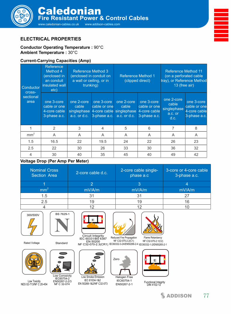
www.caledonian-cables.co.uk www.addison-cables.com
Caledonian
77ADDISON
fire Resistant Power & control cables
elecTRical PROPeRTies
conductor Operating Temperature : 90°C ambient Temperature : 30°C
current-carrying capacities (amp)
Conductor cross-
sectional area
Reference Method 4
(enclosed in an conduit
insulated wall etc)
Reference Method 3(enclosed in conduit on a wall or ceiling, or in
trunking)
Reference Method 1 (clipped direct)
Reference Method 11(on a perforated cable
tray), or Reference Method 13 (free air)
one 3-core cable or one 4-core cable 3-phase a.c.
one 2-core cable
singlephase a.c. or d.c.
one 3-core cable or one 4-core cable 3-phase a.c.
one 2-core cable
singlephase a.c. or d.c.
one 3-core cable or one 4-core cable 3-phase a.c.
one 2-corecable
singlephasea.c. or
d.c.
one 3-corecable or one4-core cable3-phase a.c.
1 2 3 4 5 6 7 8
mm2 A A A A A A A
1.5 16.5 22 19.5 24 22 26 23
2.5 22 30 26 33 30 36 324 30 40 35 45 40 49 42
Voltage Drop (Per amp Per Meter)
Nominal CrossSection Area 2-core cable d.c. 2-core cable single-
phase a.c3-core or 4-core cable
3-phase a.c.
1 2 3 4mm2 mV/A/m mV/A/m mV/A/m1.5 31 31 272.5 19 19 164 12 12 10
Rated Voltage
300/500V
NStandard
BS 7629-1
Circuit IntegrityIEC 60331/BS 6387
EN 50200NF C32-070-2.3(CR1)
W E
Reduced Fire PropagationNF C32-070-2.2(C1)
IEC60332-3-24/EN50266-2-4
Flame RetardancyNF C32-070-2.1(C2)
IEC60332-1-2/EN50265-2-1
Low ToxicityNES 02-713/NF C 20-454
Low CorrosivityIEC60754-2
EN50267-2-2/3NF C 32-074
Low Smoke EmissionIEC 61034-1&2
EN 50268-1&2/NF C32-073
Zero
Halogen FreeIEC60754-1
EN50267-2-1
W E
DIN 4102-12Functional Integrity
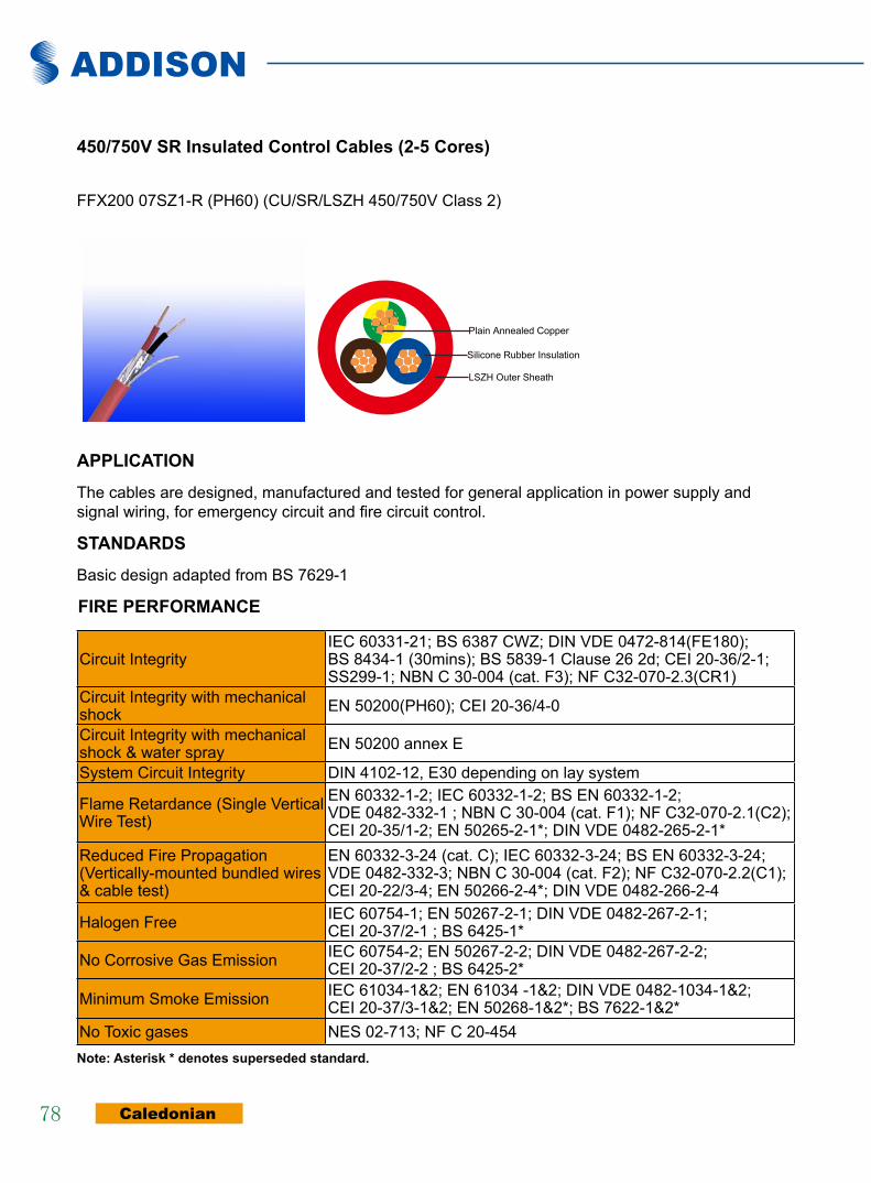
ADDISON
Caledonian78
450/750V sR insulated control cables (2-5 cores)
FFX200 07SZ1-R (PH60) (CU/SR/LSZH 450/750V Class 2)
Silicone Rubber Insulation
Plain Annealed Copper
LSZH Outer Sheath
aPPlicaTiOn
The cables are designed, manufactured and tested for general application in power supply and signal wiring, for emergency circuit and fire circuit control.
sTanDaRDs
Basic design adapted from BS 7629-1
fiRe PeRfORMance
Circuit IntegrityIEC 60331-21; BS 6387 CWZ; DIN VDE 0472-814(FE180); BS 8434-1 (30mins); BS 5839-1 Clause 26 2d; CEI 20-36/2-1; SS299-1; NBN C 30-004 (cat. F3); NF C32-070-2.3(CR1)
Circuit Integrity with mechanical shock EN 50200(PH60); CEI 20-36/4-0
Circuit Integrity with mechanical shock & water spray EN 50200 annex E
System Circuit Integrity DIN 4102-12, E30 depending on lay system
Flame Retardance (Single Vertical Wire Test)
EN 60332-1-2; IEC 60332-1-2; BS EN 60332-1-2; VDE 0482-332-1 ; NBN C 30-004 (cat. F1); NF C32-070-2.1(C2); CEI 20-35/1-2; EN 50265-2-1*; DIN VDE 0482-265-2-1*
Reduced Fire Propagation (Vertically-mounted bundled wires & cable test)
EN 60332-3-24 (cat. C); IEC 60332-3-24; BS EN 60332-3-24; VDE 0482-332-3; NBN C 30-004 (cat. F2); NF C32-070-2.2(C1); CEI 20-22/3-4; EN 50266-2-4*; DIN VDE 0482-266-2-4
Halogen Free IEC 60754-1; EN 50267-2-1; DIN VDE 0482-267-2-1; CEI 20-37/2-1 ; BS 6425-1*
No Corrosive Gas Emission IEC 60754-2; EN 50267-2-2; DIN VDE 0482-267-2-2; CEI 20-37/2-2 ; BS 6425-2*
Minimum Smoke Emission IEC 61034-1&2; EN 61034 -1&2; DIN VDE 0482-1034-1&2; CEI 20-37/3-1&2; EN 50268-1&2*; BS 7622-1&2*
No Toxic gases NES 02-713; NF C 20-454note: asterisk * denotes superseded standard.

www.caledonian-cables.co.uk www.addison-cables.com
Caledonian
79ADDISON
fire Resistant Power & control cables
VOlTaGe RaTinG
450/750 V
cable cOnsTRUcTiOn conductors: Plain annealed copper wire, stranded according to IEC 60228 class 2.insulation: Fire resistant silicone rubber compound type EI2 as per BS 7655-1.1.cabling: The cores are cabled together in concentric layers with suitable non-hygroscopic fillers.Outer sheath: Thermoplastic LSZH compound type LTS3 as per BS 7655-6.1 (Thermosetting LSZH compound type SW2-SW4 as per BS 7655-2.6 can be offered.). UV resistance, hydrocarbon resistance, oil resistance, anti rodent and anti termite properties can be offered as option.
cOlOUR cODe
insulation colour:Without Earth Conductor
2Cores Brown, Blue3Cores Brown, Gray, Black4Cores Brown, Gray, Black, Blue5Cores Brown, Gray, Black, Blue. Blacksheath colour: Colour red (other colours on request)
PHysical anD THeRMal PROPeRTies
Temperature range during operation (fixed state): -30°C – +90°CTemperature range during installation (mobile state): -20°C – +50°CMinimum bending radius: 7.5 x Overall Diameter
elecTRical PROPeRTies
Dielectric test: 2500 V r.m.s. x 5’ (core/core)Insulation resistance ≥300 MΩ x km (at 20°C)Short circuit temperature 350°C
cOnsTRUcTiOn PaRaMeTeRs
Cable Code No. of Core X Cross Section
NominalInsulationThickness
NominalSheath
Thickness
Nominal Overall
Diameter
Approx.Weight
mm2 mm mm mm kg/km2 core
FFX200 07SZ1-R (PH60) 2x1.5 0.8 1.0 7,8 96FFX200 07SZ1-R (PH60) 2x2.5 0.9 1.1 9,2 138FFX200 07SZ1-R (PH60) 2x4.0 0.9 1.2 10,5 189
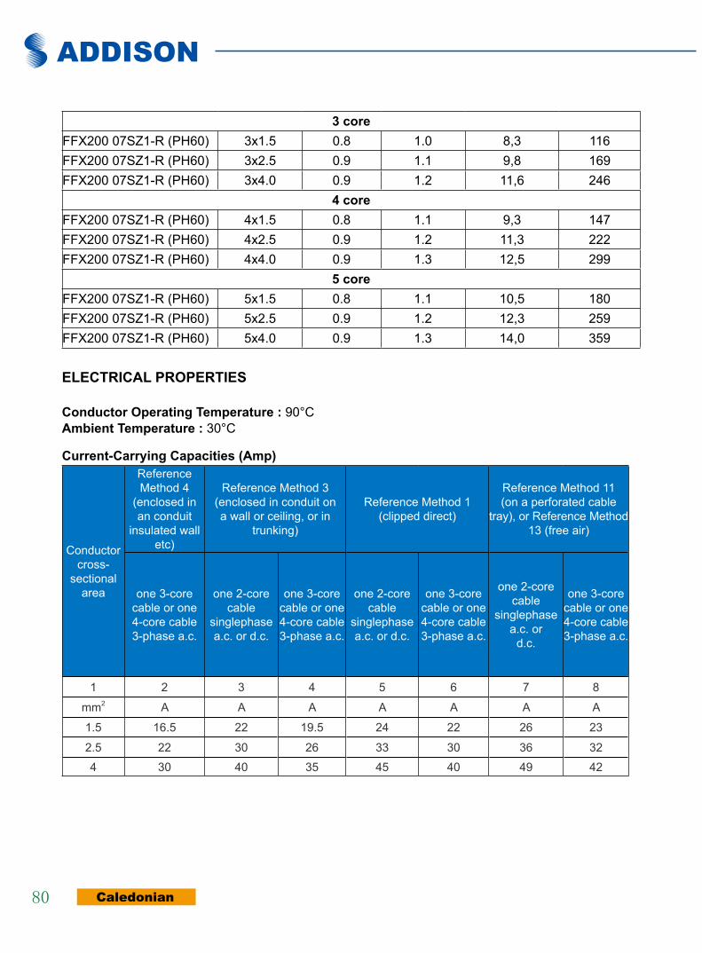
ADDISON
Caledonian80
3 coreFFX200 07SZ1-R (PH60) 3x1.5 0.8 1.0 8,3 116FFX200 07SZ1-R (PH60) 3x2.5 0.9 1.1 9,8 169FFX200 07SZ1-R (PH60) 3x4.0 0.9 1.2 11,6 246
4 coreFFX200 07SZ1-R (PH60) 4x1.5 0.8 1.1 9,3 147FFX200 07SZ1-R (PH60) 4x2.5 0.9 1.2 11,3 222FFX200 07SZ1-R (PH60) 4x4.0 0.9 1.3 12,5 299
5 coreFFX200 07SZ1-R (PH60) 5x1.5 0.8 1.1 10,5 180FFX200 07SZ1-R (PH60) 5x2.5 0.9 1.2 12,3 259FFX200 07SZ1-R (PH60) 5x4.0 0.9 1.3 14,0 359
elecTRical PROPeRTies
conductor Operating Temperature : 90°C ambient Temperature : 30°C
current-carrying capacities (amp)
Conductor cross-
sectional area
Reference Method 4
(enclosed in an conduit
insulated wall etc)
Reference Method 3(enclosed in conduit on a wall or ceiling, or in
trunking)
Reference Method 1 (clipped direct)
Reference Method 11(on a perforated cable
tray), or Reference Method 13 (free air)
one 3-core cable or one 4-core cable 3-phase a.c.
one 2-core cable
singlephase a.c. or d.c.
one 3-core cable or one 4-core cable 3-phase a.c.
one 2-core cable
singlephase a.c. or d.c.
one 3-core cable or one 4-core cable 3-phase a.c.
one 2-corecable
singlephasea.c. or
d.c.
one 3-corecable or one4-core cable3-phase a.c.
1 2 3 4 5 6 7 8
mm2 A A A A A A A
1.5 16.5 22 19.5 24 22 26 23
2.5 22 30 26 33 30 36 324 30 40 35 45 40 49 42
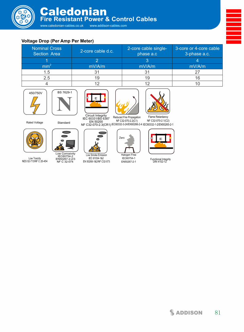
www.caledonian-cables.co.uk www.addison-cables.com
Caledonian
81ADDISON
fire Resistant Power & control cables
Voltage Drop (Per amp Per Meter)Nominal CrossSection Area 2-core cable d.c. 2-core cable single-
phase a.c3-core or 4-core cable
3-phase a.c.1 2 3 4
mm2 mV/A/m mV/A/m mV/A/m1.5 31 31 272.5 19 19 164 12 12 10
Rated Voltage
450/750V
NStandard
BS 7629-1
Circuit IntegrityIEC 60331/BS 6387
EN 50200NF C32-070-2.3(CR1)
W E
Reduced Fire PropagationNF C32-070-2.2(C1)
IEC60332-3-24/EN50266-2-4
Flame RetardancyNF C32-070-2.1(C2)
IEC60332-1-2/EN50265-2-1
Low ToxicityNES 02-713/NF C 20-454
Low CorrosivityIEC60754-2
EN50267-2-2/3NF C 32-074
Low Smoke EmissionIEC 61034-1&2
EN 50268-1&2/NF C32-073
Zero
Halogen FreeIEC60754-1
EN50267-2-1
W E
DIN 4102-12Functional Integrity
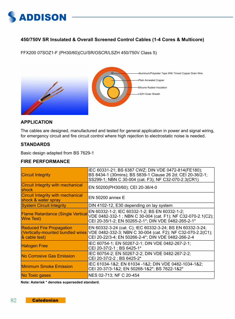
ADDISON
Caledonian82
450/750V sR insulated & Overall screened control cables (1-4 cores & Multicore)
FFX200 07SOZ1-F (PH30/60)(CU/SR/OSCR/LSZH 450/750V Class 5)
Silicone Rubber Insulation
Plain Annealed Copper
Aluminum/Polyester Tape With Tinned Copper Drain Wire
LSZH Outer Sheath
aPPlicaTiOn
The cables are designed, manufactured and tested for general application in power and signal wiring, for emergency circuit and fire circuit control where high rejection to electrostatic noise is needed.
sTanDaRDs
Basic design adapted from BS 7629-1
fiRe PeRfORMance
Circuit IntegrityIEC 60331-21; BS 6387 CWZ; DIN VDE 0472-814(FE180); BS 8434-1 (30mins); BS 5839-1 Clause 26 2d; CEI 20-36/2-1; SS299-1; NBN C 30-004 (cat. F3); NF C32-070-2.3(CR1)
Circuit Integrity with mechanical shock EN 50200(PH30/60); CEI 20-36/4-0
Circuit Integrity with mechanical shock & water spray EN 50200 annex E
System Circuit Integrity DIN 4102-12, E30 depending on lay system
Flame Retardance (Single Vertical Wire Test)
EN 60332-1-2; IEC 60332-1-2; BS EN 60332-1-2; VDE 0482-332-1 ; NBN C 30-004 (cat. F1); NF C32-070-2.1(C2); CEI 20-35/1-2; EN 50265-2-1*; DIN VDE 0482-265-2-1*
Reduced Fire Propagation (Vertically-mounted bundled wires & cable test)
EN 60332-3-24 (cat. C); IEC 60332-3-24; BS EN 60332-3-24; VDE 0482-332-3; NBN C 30-004 (cat. F2); NF C32-070-2.2(C1); CEI 20-22/3-4; EN 50266-2-4*; DIN VDE 0482-266-2-4
Halogen Free IEC 60754-1; EN 50267-2-1; DIN VDE 0482-267-2-1; CEI 20-37/2-1 ; BS 6425-1*
No Corrosive Gas Emission IEC 60754-2; EN 50267-2-2; DIN VDE 0482-267-2-2; CEI 20-37/2-2 ; BS 6425-2*
Minimum Smoke Emission IEC 61034-1&2; EN 61034 -1&2; DIN VDE 0482-1034-1&2; CEI 20-37/3-1&2; EN 50268-1&2*; BS 7622-1&2*
No Toxic gases NES 02-713; NF C 20-454note: asterisk * denotes superseded standard.

www.caledonian-cables.co.uk www.addison-cables.com
Caledonian
83ADDISON
fire Resistant Power & control cables
VOlTaGe RaTinG
450/750 V
cable cOnsTRUcTiOn
conductors: Plain annealed copper wire, flexible according to IEC 60228 class 5.insulation: Fire resistant silicone rubber compound type EI2 as per BS 7655-1.1.cabling: The cores are cabled together in concentric layers with suitable non-hygroscopic fillers.Overall screen: Aluminum/polyester tape with tinned copper drain wire. Outer sheath: Thermoplastic LSZH compound type LTS3 as per BS 7655-6.1 Thermosetting LSZH compound type SW2-SW4 as per BS 7655-2.6 can be offered.). UV resistance, hydrocarbon resistance, oil resistance, anti rodent and anti termite properties can be offered as option.
cOlOUR cODe
insulation colour:Without Earth Conductor
2Cores Brown, Blue3Cores Brown, Gray, Black4Cores Brown, Gray, Black, Blue7Cores Centre: Brown, 1st layer: Brown -Black -4 Cores White 12Cores Centre: Brown, Black -White 1st layer: Brown -Black -7 Cores White
19Cores Centre: Brown , 1st layer: Brown -Black -4 Cores White 2nd layer: Brown -black -10 Cores White
sheath colour: Colour red (other colours on request)
PHysical anD THeRMal PROPeRTies
Temperature range during operation (fixed state): -30°C – +90°CTemperature range during installation (mobile state): -20°C – +50°CMinimum bending radius: 7.5 x Overall Diameter
elecTRical PROPeRTies
Dielectric test: 2500 V r.m.s. x 5’ (core/core)Insulation Resistance ≥300 MΩ x km (at 20°C)Short circuit Temperature 350°C
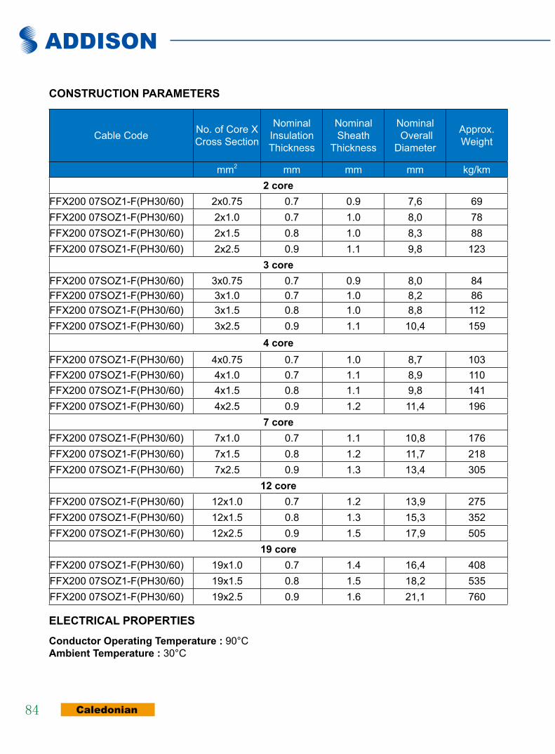
ADDISON
Caledonian84
cOnsTRUcTiOn PaRaMeTeRs
Cable Code No. of Core X Cross Section
NominalInsulationThickness
NominalSheath
Thickness
Nominal Overall
Diameter
Approx.Weight
mm2 mm mm mm kg/km2 core
FFX200 07SOZ1-F(PH30/60) 2x0.75 0.7 0.9 7,6 69FFX200 07SOZ1-F(PH30/60) 2x1.0 0.7 1.0 8,0 78FFX200 07SOZ1-F(PH30/60) 2x1.5 0.8 1.0 8,3 88FFX200 07SOZ1-F(PH30/60) 2x2.5 0.9 1.1 9,8 123
3 coreFFX200 07SOZ1-F(PH30/60) 3x0.75 0.7 0.9 8,0 84FFX200 07SOZ1-F(PH30/60) 3x1.0 0.7 1.0 8,2 86FFX200 07SOZ1-F(PH30/60) 3x1.5 0.8 1.0 8,8 112FFX200 07SOZ1-F(PH30/60) 3x2.5 0.9 1.1 10,4 159
4 coreFFX200 07SOZ1-F(PH30/60) 4x0.75 0.7 1.0 8,7 103FFX200 07SOZ1-F(PH30/60) 4x1.0 0.7 1.1 8,9 110FFX200 07SOZ1-F(PH30/60) 4x1.5 0.8 1.1 9,8 141FFX200 07SOZ1-F(PH30/60) 4x2.5 0.9 1.2 11,4 196
7 coreFFX200 07SOZ1-F(PH30/60) 7x1.0 0.7 1.1 10,8 176FFX200 07SOZ1-F(PH30/60) 7x1.5 0.8 1.2 11,7 218FFX200 07SOZ1-F(PH30/60) 7x2.5 0.9 1.3 13,4 305
12 coreFFX200 07SOZ1-F(PH30/60) 12x1.0 0.7 1.2 13,9 275FFX200 07SOZ1-F(PH30/60) 12x1.5 0.8 1.3 15,3 352FFX200 07SOZ1-F(PH30/60) 12x2.5 0.9 1.5 17,9 505
19 coreFFX200 07SOZ1-F(PH30/60) 19x1.0 0.7 1.4 16,4 408FFX200 07SOZ1-F(PH30/60) 19x1.5 0.8 1.5 18,2 535FFX200 07SOZ1-F(PH30/60) 19x2.5 0.9 1.6 21,1 760
elecTRical PROPeRTies
conductor Operating Temperature : 90°C ambient Temperature : 30°C
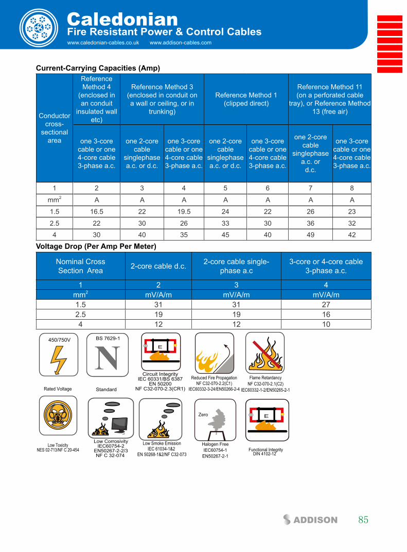
www.caledonian-cables.co.uk www.addison-cables.com
Caledonian
85ADDISON
fire Resistant Power & control cables
current-carrying capacities (amp)
Conductor cross-
sectional area
Reference Method 4
(enclosed in an conduit
insulated wall etc)
Reference Method 3(enclosed in conduit on a wall or ceiling, or in
trunking)
Reference Method 1 (clipped direct)
Reference Method 11(on a perforated cable
tray), or Reference Method 13 (free air)
one 3-core cable or one 4-core cable 3-phase a.c.
one 2-core cable
singlephase a.c. or d.c.
one 3-core cable or one 4-core cable 3-phase a.c.
one 2-core cable
singlephase a.c. or d.c.
one 3-core cable or one 4-core cable 3-phase a.c.
one 2-corecable
singlephasea.c. or
d.c.
one 3-corecable or one4-core cable3-phase a.c.
1 2 3 4 5 6 7 8
mm2 A A A A A A A
1.5 16.5 22 19.5 24 22 26 23
2.5 22 30 26 33 30 36 32
4 30 40 35 45 40 49 42
Voltage Drop (Per amp Per Meter)
Nominal CrossSection Area 2-core cable d.c. 2-core cable single-
phase a.c3-core or 4-core cable
3-phase a.c.
1 2 3 4mm2 mV/A/m mV/A/m mV/A/m1.5 31 31 272.5 19 19 164 12 12 10
Rated Voltage
450/750V
NStandard
BS 7629-1
Circuit IntegrityIEC 60331/BS 6387
EN 50200NF C32-070-2.3(CR1)
W E
Reduced Fire PropagationNF C32-070-2.2(C1)
IEC60332-3-24/EN50266-2-4
Flame RetardancyNF C32-070-2.1(C2)
IEC60332-1-2/EN50265-2-1
Low ToxicityNES 02-713/NF C 20-454
Low CorrosivityIEC60754-2
EN50267-2-2/3NF C 32-074
Low Smoke EmissionIEC 61034-1&2
EN 50268-1&2/NF C32-073
Zero
Halogen FreeIEC60754-1
EN50267-2-1
W E
DIN 4102-12Functional Integrity

ADDISON
Caledonian86
600/1000V SR Insulated Flexibles Control Cables (2-4 Cores & Multicore)
FFX400 1SZ1-R(PH60)(CU/SR/LSZH 600/1000V Class 2) FFX400 1SZ1-F(PH60)(CU/SR/LSZH 600/1000V Class 5)
Silicone Rubber InsulationPlain Annealed Copper
LSZH Outer Sheath
aPPlicaTiOnThe cables are designed for power supply and signals trasmission, indoor or outdoor even wet environment. They are designed for fixed laying in free air, in pipe or conduit, on masonry and metal structures or suspended in places where in case of fire people are exposed to serious risks for emission of smoke, toxic and corrosive gases and where you want to avoid damage to facilities, equipment, goods. They are primarily intended for feeding of: emergency exits, alarm signals, warning of smoke or gas, escalators.
sTanDaRDs
Basic design adapted from BS 7629-1
fiRe PeRfORMance
Circuit IntegrityIEC 60331-21; BS 6387 CWZ; DIN VDE 0472-814(FE180); BS 8434-1 (30mins); BS 5839-1 Clause 26 2d; CEI 20-36/2-1; SS299-1; NBN C 30-004 (cat. F3); NF C32-070-2.3(CR1)
Circuit Integrity with mechanical shock EN 50200(PH60); CEI 20-36/4-0
Circuit Integrity with mechanical shock & water spray EN 50200 annex E
System Circuit Integrity DIN 4102-12, E30 depending on lay system
Flame Retardance (Single Vertical Wire Test)
EN 60332-1-2; IEC 60332-1-2; BS EN 60332-1-2; VDE 0482-332-1 ; NBN C 30-004 (cat. F1); NF C32-070-2.1(C2); CEI 20-35/1-2; EN 50265-2-1*; DIN VDE 0482-265-2-1*
Reduced Fire Propagation (Vertically-mounted bundled wires & cable test)
EN 60332-3-24 (cat. C); IEC 60332-3-24; BS EN 60332-3-24; VDE 0482-332-3; NBN C 30-004 (cat. F2); NF C32-070-2.2(C1); CEI 20-22/3-4; EN 50266-2-4*; DIN VDE 0482-266-2-4
Halogen Free IEC 60754-1; EN 50267-2-1; DIN VDE 0482-267-2-1; CEI 20-37/2-1 ; BS 6425-1*
No Corrosive Gas Emission IEC 60754-2; EN 50267-2-2; DIN VDE 0482-267-2-2; CEI 20-37/2-2 ; BS 6425-2*

www.caledonian-cables.co.uk www.addison-cables.com
Caledonian
87ADDISON
fire Resistant Power & control cables
Minimum Smoke Emission IEC 61034-1&2; EN 61034 -1&2; DIN VDE 0482-1034-1&2; CEI 20-37/3-1&2; EN 50268-1&2*; BS 7622-1&2*
No Toxic gases NES 02-713; NF C 20-454note: asterisk * denotes superseded standard.
VOlTaGe RaTinG
600/1000 V
cable cOnsTRUcTiOn
conductors:Plain annealed copper wire, stranded for section up to 10mm2 according to IEC 60228 class 2 or flexible for section above 10mm2 according to IEC 60228 class 5.insulation: Fire resistant silicone rubber compound type EI2 as per BS 7655-1.1.cabling: The cores are cabled together in concentric layers with suitable non-hygroscopic fillers.Outer sheath: Thermoplastic LSZH compound type LTS3 as per BS 7655-6.1 (Thermosetting LSZH compound type SW2-SW4 as per BS 7655-2.6 can be offered.). UV resistance, hydrocarbon resistance, oil resistance, anti rodent and anti termite properties can be offered as option.
cOlOUR cODe
insulation colour:Without Earth Conductor
2Cores Brown, Blue3Cores Brown, Gray, Black4Cores Brown, Gray, Black, Blue5Cores Brown, Gray, Black, Blue,Blacksheath colour: Colour red or white (other colours on request)
PHysical anD THeRMal PROPeRTies
Temperature range during operation (fixed state): -30°C – +90°CTemperature range during installation (mobile state): -20°C – +50°CMinimum bending radius: 6 x Overall Diameter
elecTRical PROPeRTies
Dielectric test: 3500 V r.m.s. x 5’ (core/core)Insulation Resistance ≥300 MΩ x km (at 20°C)Short circuit Temperature 350°C

ADDISON
Caledonian88
cOnsTRUcTiOn PaRaMeTeRs
Cable Code No. of Core X Cross Section
NominalInsulationThickness
NominalSheath
Thickness
Nominal Overall
Diameter
Approx.Weight
mm2 mm mm mm kg/km2 core
FFX400 1SZ1-R(PH60) 2x1.5 1.0 1.2 9,2 124FFX400 1SZ1-R(PH60) 2x2.5 1.1 1.3 10,0 155FFX400 1SZ1-R(PH60) 2x4.0 1.1 1.4 11,2 207FFX400 1SZ1-R(PH60) 2x6.0 1.1 1.5 13,1 298FFX400 1SZ1-F(PH60) 2x10 1.1 1.6 15,9 441FFX400 1SZ1-F(PH60) 2x16 1.1 1.7 17,4 602
3 coreFFX400 1SZ1-F(PH60) 3x1.5 1.0 1.2 9,8 148FFX400 1SZ1-F(PH60) 3x2.5 1.1 1.3 10,6 188FFX400 1SZ1-F(PH60) 3x4.0 1.1 1.4 12,1 263FFX400 1SZ1-F(PH60) 3x6.0 1.1 1.5 14,4 372FFX400 1SZ1-F(PH60) 3x10 1.1 1.6 16,8 541FFX400 1SZ1-F(PH60) 3x16 1.1 1.7 19,4 777
4 coreFFX400 1SZ1-F(PH60) 4x1.5 1.0 1.3 10,6 176FFX400 1SZ1-F(PH60) 4x2.5 1.1 1.4 11,5 228FFX400 1SZ1-F(PH60) 4x4.0 1.1 1.5 13,6 332FFX400 1SZ1-F(PH60) 4x6.0 1.1 1.6 11,5 214FFX400 1SZ1-F(PH60) 4x10 1.1 1.7 18,5 680FFX400 1SZ1-F(PH60) 4x16 1.1 1.8 21,2 973
5 coreFFX400 1SZ1-F(PH60) 5x2.5 1.1 1.4 12,6 266
FFX400 1SZ1-F(PH60) 5x4.0 1.1 1.5 14,5 399FFX400 1SZ1-F(PH60) 5x6.0 1.1 1.6 17,6 576FFX400 1SZ1-F(PH60) 5x10 1.1 1.7 20,5 850FFX400 1SZ1-F(PH60) 5x16 1.1 1.8 23,3 1202
elecTRical PROPeRTies
conductor Operating Temperature : 90°C ambient Temperature : 30°C current-carrying capacities (amp)
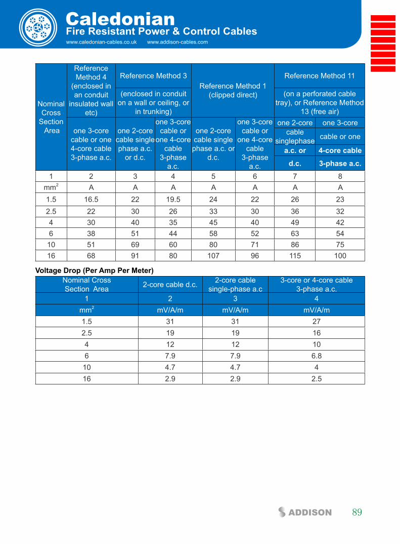
www.caledonian-cables.co.uk www.addison-cables.com
Caledonian
89ADDISON
fire Resistant Power & control cables
Nominal Cross
Section Area
Reference Method 4
(enclosed in an conduit
insulated wall etc)
Reference Method 3Reference Method 1
(clipped direct)
Reference Method 11
(enclosed in conduit on a wall or ceiling, or
in trunking)
(on a perforated cable tray), or Reference Method
13 (free air)
one 3-core cable or one 4-core cable 3-phase a.c.
one 2-core cable singlephase a.c.
or d.c.
one 3-core cable or
one 4-core cable
3-phase a.c.
one 2-core cable singlephase a.c. or
d.c.
one 3-core cable or
one 4-core cable
3-phase a.c.
one 2-core one 3-corecable
singlephase cable or one
a.c. or 4-core cable
d.c. 3-phase a.c.
1 2 3 4 5 6 7 8mm2 A A A A A A A1.5 16.5 22 19.5 24 22 26 232.5 22 30 26 33 30 36 324 30 40 35 45 40 49 426 38 51 44 58 52 63 54
10 51 69 60 80 71 86 7516 68 91 80 107 96 115 100
Voltage Drop (Per amp Per Meter) Nominal Cross Section Area 2-core cable d.c. 2-core cable
single-phase a.c3-core or 4-core cable
3-phase a.c.1 2 3 4
mm2 mV/A/m mV/A/m mV/A/m1.5 31 31 272.5 19 19 164 12 12 106 7.9 7.9 6.8
10 4.7 4.7 416 2.9 2.9 2.5
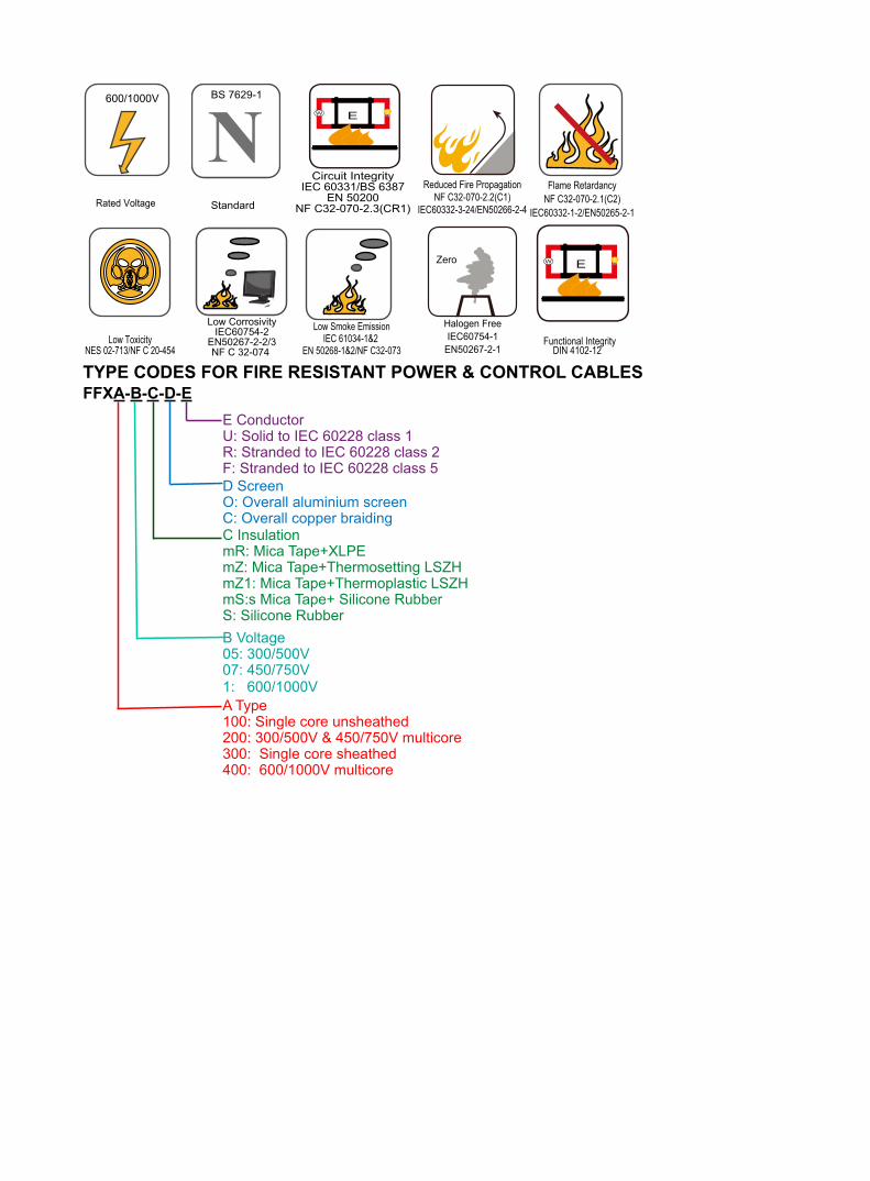
Rated Voltage
600/1000V
NStandard
BS 7629-1
Circuit IntegrityIEC 60331/BS 6387
EN 50200NF C32-070-2.3(CR1)
W E
Reduced Fire PropagationNF C32-070-2.2(C1)
IEC60332-3-24/EN50266-2-4
Flame RetardancyNF C32-070-2.1(C2)
IEC60332-1-2/EN50265-2-1
Low ToxicityNES 02-713/NF C 20-454
Low CorrosivityIEC60754-2
EN50267-2-2/3NF C 32-074
Low Smoke EmissionIEC 61034-1&2
EN 50268-1&2/NF C32-073
Zero
Halogen FreeIEC60754-1
EN50267-2-1
W E
DIN 4102-12Functional Integrity
TyPe cODes fOR fiRe ResisTanT POWeR & cOnTROl cablesffxa-b-c-D-e
B Voltage05: 300/500V07: 450/750V1: 600/1000V
C InsulationmR: Mica Tape+XLPEmZ: Mica Tape+Thermosetting LSZHmZ1: Mica Tape+Thermoplastic LSZHmS:s Mica Tape+ Silicone Rubber S: Silicone Rubber
D ScreenO: Overall aluminium screenC: Overall copper braiding
A Type100: Single core unsheathed200: 300/500V & 450/750V multicore300: Single core sheathed400: 600/1000V multicore
E ConductorU: Solid to IEC 60228 class 1R: Stranded to IEC 60228 class 2F: Stranded to IEC 60228 class 5

Address:
Marchants Industrial Centre, Mill Lane, Laughton, Lewes,
East Sussex, BN8 6AJ, UK
Tel: 44(0) 207 4195087
Fax: 44(0) 207 831 9489
E-mail:[email protected]
www.caledonian-cables.com
FireflexFire Resistant Cable
CaledonianAddress:
Marchants Industrial Centre, Mill Lane, Laughton, Lewes,
East Sussex, BN8 6AJ, UK
Tel: 44(0) 207 4195087
Fax: 44(0) 207 8319489
E-mail:[email protected]
www.caledonian-cables.co.uk
Address:
Marchahahahahahahahaahahahahahahahaahahahahahahahaahahaahahahahahaaaahaaaahaaaahaaaaaaaahaaahaaahaaahaahaahahaaaahahahahaaaaaaaaahahaaaaaaaaaaaaaaaaaahaaaaaaaaaaahaaaaaahhaaaaaaaaahaahhaaaaaaahhaahahhhaaaahhhhaaaaahhhhaaahhhhaaaaahhhhhhhhaahhhhhhaaaaahhhhhaaahhhhhaannntntntttntntntntnnttnttntnttntntnnntntntntntntntntnnntntntntntntntnnntntntntnnnnnntntnnntttntntntnnnttnnntntnntnttntnnnnnntttntttnnttntnnntntnntttnttntttnnntnnttnntnntn ssssssss s sssssssssssssssssssss IIInIInInInInnInIInInInInnInInInInInnInnnnnnnnnnnnnddddddddddududududududududddudududddudduddududdudddduuuuusstststsstststssststststtststs riririririririririr aaalllalalalalalaalallalaalalaalalallalalaaallalall CCCCCCCCCCCCCCCCCCCCCCC CC CCCC CCCCCCCCCCCCCCCCCCCCCCCCCCCCCCCCCCCeeeeeeeeeeneeeeeeeeeeeeeeeeeeeee tre, MMMMMMMMMMMMMilililililillilililllllliililllilllllililiiilllliliiliiiiliiiiiiiliiiliiiliilliilllllllllllllllllllllllllllllllllllllllllllllllllllllllll
EaEEaEaEEaaEEaEaEaEaaEaEaEaEaEaEaEaEaEaEaEaEaEaEaEaEaEaEaEaEaEaaEaEaaEaEaEaaEaEaEaEaEaEaEaEaaaaEaEaEaaEEaEaaEaEaEaEaEaEaaEaaaaEEaEaEaEaEEaaaaEaEaEEaaaaEEEEaaaaEaEaEEEaaaaEEaaEEEEEaaaEaEaEEEEaEaEEEEEEaEaEaEEEaaaEEEEEaEEEEEaaaEEEaEaaaaaEEEEEEEEaEaaaaEEEEaaaEEEaaEEEEEEaaaEEEEEEEaEaaaEEEEEEEaaaaEEEEEaaEEEEEaaEEEaaEEEaaaaEaaaaEaaaaaEEaaaaaaassssstststtstststsstststsststtststtssttttststsststsstststststststststststttssssststsstsssstsststssttsttsstssttsstststssstsssssstttttst S SS S SSSSSSSSSS S S SSSSSSSSSSSSSuuuuuusususususususususuuuusususuusuussuussussussussssssseesesesesssesseseseeeeexxxxxxx,xxx,x,x,x,,,, BBBBBBBB BBBBBBBBBBBBBBBBBBBBBBBBBBBBBBBNNNNNNNNNN8NN8N8N8N88N8N8N8N8N8N8N8N8N8NN8N8N88N8N888N8NN8NNNNN8N8NNNNN8N8NNNNNNN8NN 666 666AJ, UKKUKUKUKKUKKKKKKKUKUKKKKKKKKKKUKKKKKKKKKKKKKKKKKKKKKKKUKKKKKKKKKKKKKKKKKKKKKKKKKKKKKKKKKKKKKKKKKKKKKKKKKKKKKKKUKKUKKKKKKKUKKKKKKKKKKKUKKKUKKKKKKKKKKKKUUKKUKKKKKKKUKUKKUUKKKKUUUKKKKKKKKKKKKKKKKKKKKKUUKKKKKKKKKKKKUUUKKKKKKKKKKKKKKKKKKKKKU
TTTTTTeTeTeTeTeTeTeTTeTTTeTTeTeTeTTeTTTeTeTeTeTeeTeTeTeTeeTeeeeeTTeeeeeelllllll:l:l:l:ll:l:llll:l::ll:ll:llll:l:: 4444444444 4 44444444444(4(4(4(4(4(4((44(4(4(4(4((((((000000)0)0)0)0)0)0)0)00)0)0)0)0)0)0)0)0)0)0)0))))0)0))0)0))0))))))))))) 222222222222222222222222 222 2 2222222222222222222200000000000000070707070707070007707000000000 41950505050500500005000000050000500000000000000000000500000000000000000000000000005000888887878787878787878787787787778878787787888777787778788878787787878788888878787878787888888778787878888787888887878888777788887788888877887878888787878887787888888787788788888787878777787778778777788778787788888778787788878
FFFFFFaFaFaFaFaFaFaFaaaFaaaaaaaaaxxxxxx:x:x:x:x:x:x:x::xx:xx:x:xxx:x:x:xxx:x:x:x::xx:xxxx::x::x:::x:: 4444444444444444444444 4444444 444444444444444444444444(4444444 0) 2077777777777777777777777777777777777777 88888888888888888888888888888888888888 88888888888888888888888888888888888888888888888888888888888833333333333313131331313131333331313131313333333313333131313331333331313313133113133313133333333113333313333131133133313333333333333 999999999999 99999444848484848488484888484 999999999999999999
EEEEEEEEEEEEEE-EE-EEEEEEEEEEEEEEEEEE mail:ssssssssssssssssssssssssssssssssssssalalalalalalallallllllalalllllalalllalalaallallalallalaallaaalaaaalalaaalalalalallalalaallaaalalaaaalalalalaalalalaaaaalllalallaaalllaalllllalallllllaaallaallaaa eeeeeeeeeeeeeesesesesesseseseseeeeeeeseseeeeeeeseseseseeeeeeesseeeeeeeeeeseeeeeeeeeseeesesssees@c@c@@@@@@@c@c@@@@@@@@@@c@@c@@@@c@cc@ccaaaalalalalalalalalalalaleededededededededededededdeddde ooooononononononnnnnnnnnnnnonnnonnnniiiiaaaaaaiaiaiiaiaiaaiaaiaiaiaaiiaiiaiaiiaaiaiaiaaiaiaiaaaaiaiiaaiaaaiiaaaaaaaaaaaaaaaaaaaaaaaaaaaaaaaaaaaaaaaaaaaaaaaaiaaaaaaaaaaannnnnnnnnnnn-n-nnnnnnnnnnnnnnnnnnnnnnnnnnnnnnnnnnnnnnnnnnnnnnnnnnnnnnnnnnnnnnnnnnnnnn cablesessessssesssssssssssesssssessesssssssessssesesssssesesessesessssesssessseeessee
wwwwwwwwwwwwwwwwwwwwwwwwwwwwwwwwwwwwwwwwwwwwwwwwwwwwwwwwwwwwwwwwwwwwwwwwwwwwwwwwwwwwwwwwwwwwwwwwwwwwwwwwwwwwwwwwwwwwwwwwwwwwwwwwwww.wwwwwwwwwwwww.wwwwww.wwwwwwww.w.wwwww.wwwwww.wwwww.www.wwwww.www.www.www.wwwww.wwwwwwww.wwww ccccacaccaccacacacccacacallleleleleleleeeedddddododododododododooooodoooooooonnnnnininininnnininnninininiaaaaananananannnnnnnnaannnnnnannnnnn-c-cc-cc-c-c-c-ccc-c-c-c-ccc-cc-c-cc-cccc-c-cccc-ccccccccccccccccccccccccccccccccccccccccccccccccccccccccccccccccaabaaabaaababababababababababababaabababababbaaababaababbbababababbbababbbbbabbbbbbabbbbbabbabbbabbbaababaaaaaaaaaaaaaaaaaaaaaaaaaaaaaaaaaaaaaa les.cocoocoococoocooocoooocooooooooooocooooooooooooooocooooooooommmmmmmmmmmmmmmmmmmmmmmmmmmmmmmmmmmmmmmmmmmmmmmmmmmmmmmmmmmmmmmm