fire station design - home | fire and emergency new … design manual for fire stations this...
TRANSCRIPT

Design manual (fire) 1
Fire Station Design Design manual (fire)
Version 3.0 (26 February, 2016)

Fire Design Manual for Fire Stations
This document Fire Station Design Manual (Fire) Version: 3 Date: 26 February 2016 is issued as guidance under Section 175 of the Building Act 2004. While the New Zealand Fire Service (NZFS) has taken care in preparing this document, and MBIE has reviewed it, it is only a guide and does not relieve any person of the obligation to consider any matter to which that information relates, according to the circumstances of the case.
Introduction
Fire stations are specialist buildings that have features and operational requirements that are not reflected in the Acceptable Solutions and Verification Methods, used to demonstrate compliance with the Building Code Clauses, C1 to C6 Protection from Fire.
New Zealand places high expectations on the functioning of fire stations given their importance to society. As such the NZFS requires that fire design of fire stations needs to consider issues in addition to meeting the requirements of the Building Code for their operational requirements.
The Fire Station Design Manual (Fire) Version: 3 Date: 26 February 2016 (the design manual) has been produced by NZFS specifically for fire design of fire stations.
The NZFS operates out of approximately 440 fire stations around New Zealand. In addition to being significant community assets, these buildings are critical to maintaining the emergency response capability of the NZFS and are required to remain operational following a natural disaster.
Fire Station Design Manual (Fire)
The design manual takes a risk based approach towards fire protection with increased protection for those stations that are critical to maintaining the operational network of fire stations. The design manual is to be specifically used for NZFS Fire Stations.
The design manual has been verified and independently reviewed. MBIE is satisfied that fire designs complying with the methodology in the design manual will meet the performance criteria of the Building Code.

Who the design manual is for
The design manual is intended to be used by:
Design professionals involved in the fire design of fire stations.
Building Consent Authorities (BCAs) to assist in deciding if the proposed building work meets the Building Code.
NZFS to understand benchmark for fire designs for these buildings. It is recommended that BCAs use the design manual when considering whether to issue a building consent for a fire station.
Fire designs that follow the design manual are considered to achieve the performance requirements of Building Code Clauses C1 to C6 Protection from Fire.
Design considerations
The following is a description of the fire design and consenting process for fire stations using the design manual:
The designer will develop fire designs based on the design manual and submit a building consent application to the BCA as means of complying with the Building Code
A Fire Engineering Brief (FEB) and Peer Review are not required for fire designs that are based on the design manual, fire designs based on the design manual have been independently verified on behalf of MBIE to comply with the Building Code
Under Section 46 of the Building Act applications for building consents using this manual shall be provided to the NZFS, to enable the NZFS to comment on the provisions for the means of escape from fire, and the needs of persons authorized by law to enter buildings to undertake fire-fighting.
Alterations to Existing Buildings Under Section 112 of the Building Act, a BCA must not grant a building consent to alter all or part of an existing building unless it is satisfied that, after the alteration, the building will (among other things) comply as nearly as is reasonably practicable (ANARP) with the Building Code provisions relating to means of escape from fire.
When designers and BCAs are considering existing buildings and s112 and s115 upgrading requirements for means of escape, the design manual can be used as the basis of compliance with the Building Code “as nearly as is reasonably practicable”.
MBIE Guidance: ‘Requesting information about means of escape from fire for existing buildings’ can be used to assist in gathering the information required about buildings. The minimum level of assessment would usually be expected to be a ‘gap assessment’ which should be assessed against the requirements of the design manual.
Any proposed alterations to existing fire stations other than minor works must also be
provided to the NZFS for comment as stipulated in Section 46 of the Building Act.

Design manual (fire) 3
Table of contents
1. General ..................................................................................................................................................... 16
1.1. Introduction and scope ................................................................................................................ 16
1.2. Using this design manual ............................................................................................................. 17
1.3. Calculating occupant load ............................................................................................................ 18
2. Firecells, fire safety systems and fire resistance ratings .......................................................................... 20
2.1. Provision of firecells ..................................................................................................................... 20
2.2. Fire safety systems ...................................................................................................................... 20
2.3. Fire resistance ratings ................................................................................................................. 21
3. Means of escape ...................................................................................................................................... 23
3.1. General principles ........................................................................................................................ 23
3.2. Number of escape routes ............................................................................................................ 24
3.3. Height and width of escape routes .............................................................................................. 24
3.4. Length of escape routes .............................................................................................................. 27
3.5. Escape from basements .............................................................................................................. 30
3.6. Open paths .................................................................................................................................. 30
3.7. Special cases for open paths ....................................................................................................... 31
3.8. Dead ends .................................................................................................................................... 33
3.9. Exitways ....................................................................................................................................... 33
3.10. Control of exitway activities ......................................................................................................... 34
3.11. External escape routes ................................................................................................................ 35
3.12. Final exits ..................................................................................................................................... 38
3.13. Single escape routes ................................................................................................................... 38
3.14. Doors subdividing escape routes................................................................................................. 38
3.15. Signs ............................................................................................................................................ 42
4. Control of internal fire and smoke spread ................................................................................................ 43
4.1. Firecells ........................................................................................................................................ 43
4.2. Glazing in fire and smoke separations ........................................................................................ 43
4.3. Structural stability during fire ....................................................................................................... 43
4.4. Fire stopping ................................................................................................................................ 45
4.5. Firecell construction ..................................................................................................................... 45
4.6. Specific requirements for sleeping area firecells ......................................................................... 47
4.7. Exitways ....................................................................................................................................... 47
4.8. Intermittent activities .................................................................................................................... 48
4.9. Protected shafts ........................................................................................................................... 49
4.10. Long corridor subdivision ............................................................................................................. 50
4.11. Floors ........................................................................................................................................... 51

Design manual (fire) 4
4.12. Subfloor spaces ........................................................................................................................... 51
4.13. Concealed spaces ....................................................................................................................... 52
4.14. Closures in fire and smoke separations ...................................................................................... 55
4.15. Interior surface finishes, floor coverings and suspended flexible fabrics .................................... 60
4.16. Building services plant ................................................................................................................. 62
5. Control of external fire spread .................................................................................................................. 63
5.1. Fire separation for buildings with more than one title .................................................................. 63
5.2. Horizontal fire spread from external walls ................................................................................... 63
5.3. FRRs for external walls ................................................................................................................ 64
5.4. Method 1 - Small openings and fire resisting glazing .................................................................. 65
5.5. Method 2: Enclosing rectangles – parallel boundary ................................................................... 67
5.6. Method 3: Enclosing rectangles – irregular buildings and non-parallel boundaries .................... 72
5.7. Method 4: Return walls and wing walls ....................................................................................... 73
5.8. Horizontal fire spread from roofs and open sided buildings ........................................................ 77
5.9. Vertical fire spread ....................................................................................................................... 79
5.10. Exterior surface finishes .............................................................................................................. 84
6. Firefighting ................................................................................................................................................ 85
6.1. Fire Service vehicular access ...................................................................................................... 85
6.2. Information for firefighters ............................................................................................................ 85
6.3. Firefighting facilities ..................................................................................................................... 85
7. Prevention of fire occurring ...................................................................................................................... 86
7.1. Solid fuel appliances .................................................................................................................... 86
7.2. Gas-burning appliances ............................................................................................................... 86
7.3. Oil-fired appliances ...................................................................................................................... 87
7.4. Downlights ................................................................................................................................... 87
7.5. Open fires .................................................................................................................................... 87
A1.1 Fire alarm and sprinkler systems ................................................................................................ 88
A1.2 Requirements common to alarm systems .................................................................................. 88
A2.1 Fire safety system descriptions ................................................................................................... 88
B1.1 Introduction .................................................................................................................................. 89
B2.1 Automatic fire sprinkler systems .................................................................................................. 89
C1.1 General ........................................................................................................................................ 90
C2.1 Flammability of floor coverings .................................................................................................... 90
C3.1 Flammability of suspended flexible fabrics and membrane structures ........................................ 90
C4.1 Properties of lining materials ....................................................................................................... 90
C5.1 Fire resistance ............................................................................................................................. 90
C6.1 Fire doors and smoke control doors ............................................................................................ 90
C7.1 Fire properties of external wall cladding systems ........................................................................ 91
D1.0 Determining a Group Number for some surface finishes ............................................................ 93
D2.0 Critical radiant flux values for some flooring materials ................................................................ 93

Design manual (fire) 5
Acknowledgments
The New Zealand Fire Service (NZFS) acknowledges the contributions provided by MBIE and BRANZ towards the development of this manual.
Note: Text and figures used with permission of MBIE.
Revision history
Revision Date Description
1.0 July 2014 Initial issue
2.0 October 2015 Revised due to stakeholder feedback
3.0 February 2016 Revised due to stakeholder feedback
Purpose of this manual
This manual is provided by the New Zealand Fire Service (NZFS) in consultation with the Ministry of Business, Innovation and Employment (MBIE). Its purpose is to assist Building Consent Authorities, building owners, designers and persons who carry out building work.
The information contained describes how the NZFS applies the requirements of the Building Act 2004 and the Building Code to achieve a specific design (an Alternative Solution) for fire station facilities. Using the manual will reduce the time and cost to develop fire designs, will ensure fire designs are prepared that are compliant with the Building Code and improve the quality of designs.

Design manual (fire) 6
Definitions
The following definitions include a number of NZFS-specific terms. A full list of definitions are available in the handbook to the New Zealand Building Code.
Term Definition
access route A continuous route that permits people and goods to move between the apron or construction edge of the building to spaces within a building, and between spaces within a building.
accessible Having features that enable use by a person with a disability.
accessible route An access route usable by a person with a disability. It shall be a continuous route that can be negotiated unaided by a wheelchair user. The route shall extend from street boundary or car parking area to those spaces within the building required to be accessible to enable a person with a disability to carry out normal activities and processes within the building.
adjacent building A nearby building, including an adjoining building, whether or not erected on other property
aerial appliance This type of fire appliance includes a basket and extendable boom to provide an aerial platform for firefighting and rescue activities.
appliance Any vehicle used to respond to fires. They are typically referred to by a type to denote their performance and capabilities.
appliance bay This is the single level portion of the station where operational vehicles and equipment are kept in a ready state to respond to incidents. The appliance bay ‘block’ may include direct supporting spaces such as lockers, toilets and decontamination facilities.
BA compressor room
This refers to the Breathing Apparatus cleaning room, which normally contains a compressor used to refill air cylinders.
basement Any firecell or part of a firecell situated below the level of the lowest final exit.
COMMENT: Because fire safety systems are increased with increases in escape height, the precautions for basements increase with basement depth. Thus a single floor building with one basement level is treated as a two floor building, and a single floor building with three basement levels as a four floor building.
boundary Means any boundary which is shown on a survey plan approved by the Surveyor-General and which is deposited in the Registrar General of Land, whether or not a new title has been issued.
brigade facilities This refers to associated crew areas such as offices, mess area, training rooms etc.
building Has the meaning ascribed to it by sections 8 and 9 of the Building Act 2004. Refers to the structures defined in sections 8 and 9 of the Building Act 2004.
COMMENT: Notwithstanding the definition of building a number of separated buildings cannot be taken as a single firecell for the purposes of this Acceptable Solution.
Building Act 2004 (the Building Act
Means the principle legislation dealing with building controls in New Zealand.
building code Means the regulations made under section 400 of the Building Act 2004.

Design manual (fire) 7
building consent Means consent to carry out building work granted by a building consent authority under Section 49 of the Building Act 2004.
building consent authority Has the meaning ascribed to it by Section 7 of the Building Act 2004.
building element Any structural and non-structural component or assembly incorporated into or associated with a building. Included are fixtures, services, drains, permanent mechanical installations for access, glazing, partitions, ceilings and temporary supports.
building height The vertical distance between the floor level of the lowest occupied space above the ground and the top of the highest occupied floor, but not including spaces located within or on the roof that enclose stairways, lift shafts or machinery rooms.
cavity barrier A construction provided to close openings within a concealed space against the passage of fire, or to restrict the spread of fire within such spaces.
combustible See non-combustible.
concealed space Any part of the space within a building that cannot be seen from an occupied space.
COMMENT: This term includes any ceiling space, roof space, space under a raised floor (such as computer rooms, floors, or stages), plenums, spaces under a tiered floor, “left-over spaces” created when some structural element or the like has been covered in small service or duct spaces within the volume of a firecell and the like. It does not include a protected shaft.
construct In relation to a building, includes to design, build, erect, prefabricate, and relocate the building. It has the same meaning as construction.
dead end The part of an open path where escape is possible in only one direction.
COMMENT: A dead end ceases to exist where the escape route reaches a point in the open path which offers alternative directions of travel, or at a final exit or an exitway.
doorset A complete assembly comprising a door leaf or leaves including any glazed or solid panels adjacent to or over the leaves within the door frame. It includes hardware or other inbuilt features, a door frame, if any, with its fixings to the wall and, for a sliding or tilting door, all guides and their respective fixings to the lintel, wall or sill.
escape height The height between the floor level in the firecell being considered and the floor level of the required final exit which is the greatest vertical distance above or below that firecell.
COMMENT: 1. It is necessary only to use the greatest height to the exits required for the firecell being considered, even though the building may have other final exits at lower or higher levels. 2. Where the firecell contains intermediate floors, or upper floors within household units the escape height shall be measured from the floor having the greatest vertical separation from the final exit.
escape route A continuous unobstructed route from any occupied space in a building to a final exit to enable occupants to reach a safe place that comprises of one or more open path or safe path.
COMMENT: Doors are not obstructions in an escape route provided they comply with this design manual and either D1/AS1 or NZS 4121.

Design manual (fire) 8
exitway All parts of an escape route protected by fire or smoke separations, or by distance when exposed to open air and terminating at a final exit.
external wall Any exterior face of a building within 30° of vertical, consisting of primary and/or secondary elements intended to provide protection against the outdoor environment, but which may also contain unprotected areas.
COMMENT: A roof is an external wall if within 30° of the vertical.
final exit The point at which an escape route terminates by giving direct access to a safe place.
COMMENT: Final exits are commonly the external doors from a ground floor, but this applies only if such doors open directly onto a safe place. If a safe place can be reached only by passing down an alley, or across a bridge, then the final exit is not reached until the end of such an alley or bridge. Final exits, therefore, should be seen strictly as a point of arrival, rather than as any particular element of a building. They are determined entirely by the definition of safe place.
fire The state of combustion during which flammable materials burn producing heat, toxic gases, or smoke or flame or any combination of these.
firecell Any space including a group of contiguous spaces on the same or different levels within a building, which is enclosed by any combination of fire separations, external walls, roofs, and floors.
COMMENT: Floors, in this context includes ground floors, and those in which the underside is exposed to the external environment (e.g. when cantilevered). Note also that internal floors between firecells are fire separations.
fire damper A device with a specified FRR complete with fixings and operating mechanism for automatically closing off an airway where it passes through a fire separation.
COMMENT: An airway may be a duct, plenum, ceiling space, roof space or similar construction used for the passage of ventilating air.
fire door A doorset, single or multi-leaf, having a specific fire resistance rating, and in certain situations a smoke control capability, and forming part of a fire separation. The door, in the event of fire, if not already closed, will close automatically and be self-latching.
fire hazard The term used to describe the danger of potential harm and degree of exposure arising from:
a) the start and spread of fire; and
b) the smoke and gases that are generated by the start and spread of fire.
fire load The sum of the net calorific values of the combustible contents which can reasonably be expected to burn within a firecell, including furnishings, built-in and removable materials, and building elements. The calorific values shall be determined at the ambient moisture content or humidity. (The unit of measurement is MJ.)
fire resistance rating (FRR)
The term used to describe the minimum fire resistance required of primary and secondary elements as determined in the standard test for fire resistance, or in accordance with a specific calculation method verified by experimental data from standard fire resistance tests. It comprises three numbers giving the time in minutes for which each of the criteria structural adequacy, integrity and insulation are satisfied, and is presented always in that order.
Design manual (fire) 9
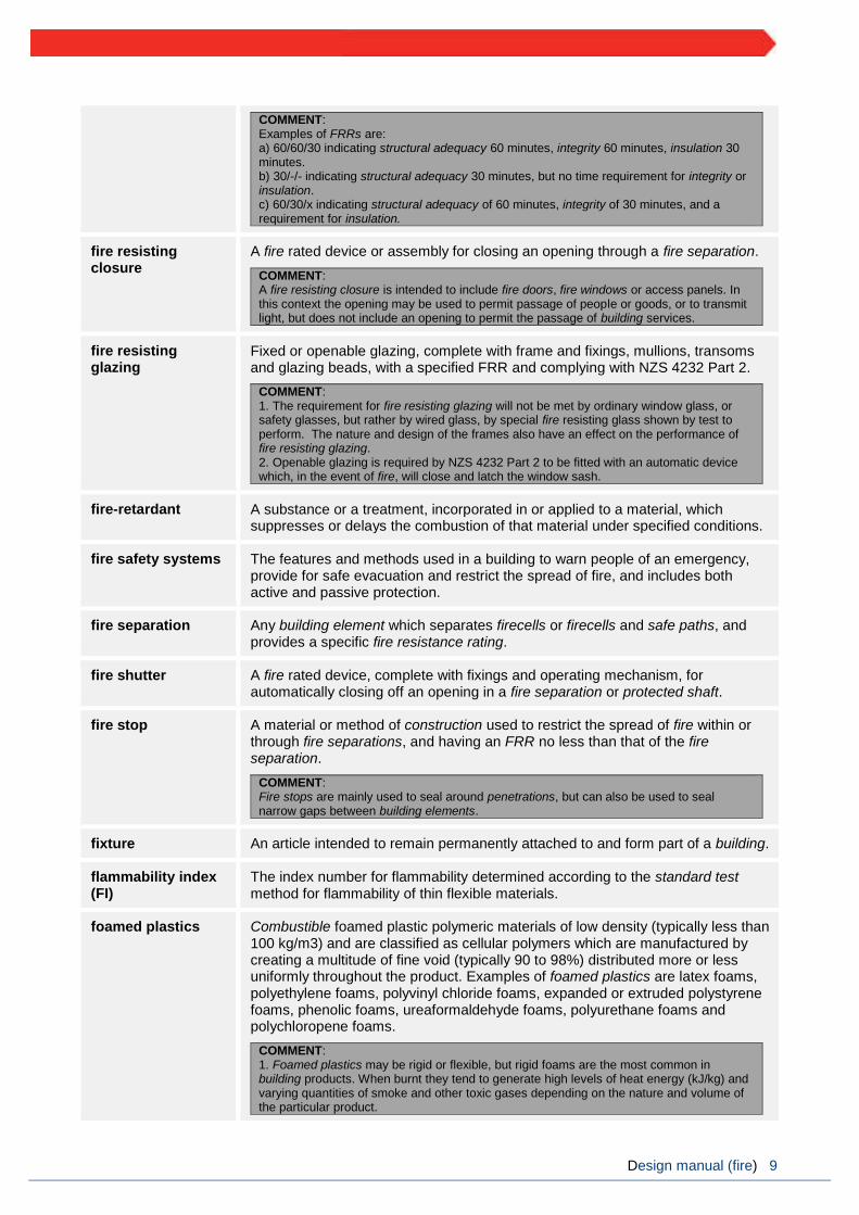
COMMENT: Examples of FRRs are: a) 60/60/30 indicating structural adequacy 60 minutes, integrity 60 minutes, insulation 30 minutes. b) 30/-/- indicating structural adequacy 30 minutes, but no time requirement for integrity or insulation. c) 60/30/x indicating structural adequacy of 60 minutes, integrity of 30 minutes, and a requirement for insulation.
fire resisting closure
A fire rated device or assembly for closing an opening through a fire separation.
COMMENT: A fire resisting closure is intended to include fire doors, fire windows or access panels. In this context the opening may be used to permit passage of people or goods, or to transmit light, but does not include an opening to permit the passage of building services.
fire resisting glazing
Fixed or openable glazing, complete with frame and fixings, mullions, transoms and glazing beads, with a specified FRR and complying with NZS 4232 Part 2.
COMMENT: 1. The requirement for fire resisting glazing will not be met by ordinary window glass, or safety glasses, but rather by wired glass, by special fire resisting glass shown by test to perform. The nature and design of the frames also have an effect on the performance of fire resisting glazing. 2. Openable glazing is required by NZS 4232 Part 2 to be fitted with an automatic device which, in the event of fire, will close and latch the window sash.
fire-retardant A substance or a treatment, incorporated in or applied to a material, which suppresses or delays the combustion of that material under specified conditions.
fire safety systems The features and methods used in a building to warn people of an emergency, provide for safe evacuation and restrict the spread of fire, and includes both active and passive protection.
fire separation Any building element which separates firecells or firecells and safe paths, and provides a specific fire resistance rating.
fire shutter A fire rated device, complete with fixings and operating mechanism, for automatically closing off an opening in a fire separation or protected shaft.
fire stop A material or method of construction used to restrict the spread of fire within or through fire separations, and having an FRR no less than that of the fire separation.
COMMENT: Fire stops are mainly used to seal around penetrations, but can also be used to seal narrow gaps between building elements.
fixture An article intended to remain permanently attached to and form part of a building.
flammability index (FI)
The index number for flammability determined according to the standard test method for flammability of thin flexible materials.
foamed plastics Combustible foamed plastic polymeric materials of low density (typically less than 100 kg/m3) and are classified as cellular polymers which are manufactured by creating a multitude of fine void (typically 90 to 98%) distributed more or less uniformly throughout the product. Examples of foamed plastics are latex foams, polyethylene foams, polyvinyl chloride foams, expanded or extruded polystyrene foams, phenolic foams, ureaformaldehyde foams, polyurethane foams and polychloropene foams.
COMMENT: 1. Foamed plastics may be rigid or flexible, but rigid foams are the most common in building products. When burnt they tend to generate high levels of heat energy (kJ/kg) and varying quantities of smoke and other toxic gases depending on the nature and volume of the particular product.

Design manual (fire) 10
2. Where doubt exists as to whether building materials are foamed plastics, an opinion should be sought from a person or organisation with appropriate skill and experience in fire engineering. That opinion should be included with the building consent application to the building consent authority.
Group Number The classification number for a material used as a finish, surface, lining, or attachment to a wall or ceiling within an occupied space and determined according to the standard test methods for measuring the properties of lining materials.
COMMENT: The method for determining or predicting a Group Number is described in Appendix D of this manual.
handrail A rail to provide support to or assist with the movement of a person.
hazardous Creating an unreasonable risk to people of bodily injury or deterioration of health.
hazardous substance
This term has the meaning ascribed to it by Section 2 Fire Service Act 1975 and Section 2 of the Hazardous Substances and New Organisms Act 1996.
hold-open device A device which holds a smoke control door or fire door open during normal use but is released by deactivating the device by an automatic fire detection system allowing the door to close automatically under the action of a self-closing device.
HVAC An abbreviation for heating, ventilating and air conditioning.
insulating material A material that has a thermal conductivity of less than 0.07 W/m K.
insulation In the context of fire protection, the time in minutes for which a prototype specimen of a fire separation when subjected to the standard test for fire resistance, has limited the transmission of heat through the specimen.
integrity In the context of fire protection, the time in minutes for which a prototype specimen, of a fire separation when subjected to the standard test for fire resistance, has prevented the passage of flame or hot gases.
COMMENT: The precise meaning of integrity depends on the type of building elements being treated and how it is defined in the standard test being used.
intended use In relation to a building, this:
a) includes any or all of the following:
i. any reasonably foreseeable occasional use that is not incompatible with the intended use
ii. normal maintenance, and
iii. activities undertaken in response to fire or any other reasonably foreseeable emergency, but
b) does not include any other maintenance and repairs or rebuilding.
intermediate floor Any upper floor within a firecell which because of its configuration provides an opening allowing smoke or fire to spread from a lower to an upper level within the firecell.
COMMENT: 1. An intermediate floor may be open to the firecell or enclosed with non-fire rated construction. If enclosed with fire rated walls another firecell is created.3. 2. This design manual allows limited area intermediate floors of 20% or 40% of the floor area depending on other fire safety requirements. In other situations C/VM2 is to be used.
life rating The fire resistance rating to be applied to elements of construction that allows movement of people from their location in a building to a safe place.

Design manual (fire) 11
means of escape from fire
In relation to a building that has a floor area, this:
a) means continuous unobstructed routes of travel from any part of the floor area of that building to a place of safety; and
b) includes all active and passive protection features required to warn people of fire and to assist in protecting people from the effects of fire in the course of their escape from the fire.
muster bay Area within the station where attending employees assemble to gather appropriate Personal Protective Equipment (PPE) prior to attending an incident. (E.g. a locker bay where PPE is kept).
non-combustible Materials classified not combustible when tested to AS 1530 Part 1.
notional boundary The boundary which, for fire safety purposes, is assumed to exist between two buildings on the same property under a single land title.
COMMENT: A notional boundary may be located anywhere between the two buildings on the same property using the following rules: 1. The notional boundary is assumed to exist in the space between the buildings and is positioned so that one of the buildings would comply with the provisions for space separation having regard to the amount of its unprotected area. In practice, if one of the buildings is existing, the position of the boundary will be set by the space separation factors for that building. 2. The siting of the new building, or the second building if both are new, can then be checked to see that it also complies, using the notional boundary as the relevant boundary for the second building. (Once the notional boundary is set for the first building, it becomes the relevant boundary for the second (new) building and does not move).
occupant load The greatest number of people likely to occupy a particular space within a building. It is determined by:
a) multiplying the number of people per m2 (occupant density) for the activity being undertaken, by the total floor area, or
b) for sleeping, care and detention areas, counting the number of resting spaces provided, or
COMMENT: See comment in paragraph 1.3.3 for counting resting spaces.
c) for fixed seating areas, counting the number of seats.
occupied space Any space within a building in which a person will be present from time to time during the intended use of the building.
open path That part of an escape route (including dead ends) within a firecell where occupants may be exposed to fire or smoke while making their escape.
open space This includes land on which there is and will be no buildings and which has no roof over any part of it other than overhanging eaves.
other property Any land or buildings, or part of any land or buildings, that are:
a) not held under the same allotment; or
b) not held under the same ownership; and includes a road.
owner In relation to any land and any buildings on that land, this:
a) means the person who:
i. is entitled to the rack rent from the land
ii. would be so entitled if the land were let to a tenant at a rack rent, and

Design manual (fire) 12
b) includes:
i. the owner of the fee simple of the land, and
ii. any person who has agreed in writing, whether conditionally or unconditionally, to purchase the land or any leasehold estate or interest in the land, or to take a lease of the land and is bound by the agreement because the agreement is still in force.
penetration A pipe, cable or duct passing through an opening in a fire separation.
person with a disability
A person who has an impairment or a combination of impairments that limits the extent to which the person can engage in the activities, pursuits, and processes of everyday life, including, without limitation, either or both of the following:
a) a physical, sensory, neurological, or intellectual impairment
b) a mental illness.
pitch line The line joining the leading edge or nosing (if any) of successive stair treads within a single flight of a stairway.
place of safety Means either:
a) a safe place; or
b) a place that is inside a building and meets the following requirements:
i. the place is constructed with fire separations that have fire resistance sufficient to withstand burnout at the point of the fire source; and
ii. the place is in a building that is protected by an automatic fire sprinkler system that complies with NZS 4541 or NZS 4515 as appropriate to the building’s use; and
iii. the place is designed to accommodate the intended number of users; and
iv. the place is provided with sufficient means of escape to enable the intended number of users to escape to a safe place that is outside a building.
primary element A building element providing the basic loadbearing capacity to the structure, and which if affected by fire may initiate instability or premature structural collapse.
COMMENT: Suspended floors in multi-storey buildings are primary elements.
property rating The fire resistance rating to be applied to elements of construction that allows for protection of other property.
protected shaft A space, other than a safe path, enclosed by fire separations or external walls used to house building services, lifts, or conveyors which pass from one firecell to another.
railway line This term has the meaning ascribed to it by Section 4 of the Railways Act 2005.
relevant boundary The boundary of an allotment which is other property in relation to the building
concerned and from which is measured the separation between the building and
that other property. For the external wall of any building, the relevant boundary
shall be the nearest of the following boundaries:
a) A boundary of a freehold allotment, except that where the other property is a road, railway line or public open space the relevant boundary is the boundary on the far side of that other property.
b) A boundary of a cross lease or of a company lease or licence, except that where the other property is open space to which the lessee or licensee of

Design manual (fire) 13
the building concerned has an exclusive right of access and occupation or to which two or more occupiers have rights of access and occupation the relevant boundary is the boundary on the far side of that other property.
c) A boundary shown on a unit plan excluding a boundary between a principal unit and its accessory unit, except that where the other property is open space which is common property, the relevant boundary is the boundary on the far side of that other property.
COMMENT: 1. Where an easement, such as a right of way, occurs within an allotment, the relevant boundary shall remain the same as if the easement did not exist. 2. Boundaries within a cross-lease or company lease or licence are shown on a survey plan. In some cases the boundary is the external wall or roof of a building. 3. The unit title boundaries of principal units, accessory units, and common property are shown in the unit plan. A boundary is frequently an internal or external wall, an upper floor, or the roof of a building. 4. A wall along a boundary between two allotments is called a “party wall” when the owners of the allotments each have legal rights in respect of that wall registered by way of easements on one or both titles. An internal wall between cross-leases, company leases, or unit titles, or between one of them and common property, is not generally called a party wall but in that case also the lessees, unit title holders, or corporate body concerned each have legal rights in respect of that wall. Such a wall separates areas which are other property in relation to each other, but the wall itself is part of each property. The fire protection consequence of that legal concept is that such a wall can be regarded as a fire separation providing protection against horizontal fire spread in each direction. In other words, that wall may provide the appropriate FRR instead of each property having its own wall of that FRR.
road This term has the meaning ascribed to it by Section 315 of the Local Government Act 1974 and includes a public place and also a motorway.
safe path That part of an exitway which is protected from the effects of fire by fire separations, external walls, or by distance when exposed to open air.
safe place A place, outside and in the vicinity of a single building unit, from which people may safely disperse after escaping the effects of a fire. It may be a place such as a street, open space, public space or an adjacent building unit.
COMMENT: The Fire Safety and Evacuation of Buildings Regulations 2006 use the term place of safety and allows the place of safety to be within the building provided that it is protected with a sprinkler system. This design manual does not include consideration of a place of safety inside the building.
secondary element A building element not providing load bearing capacity to the structure and if affected by fire, instability or collapse of the building structure will not occur.
smokecell A space within a building which is enclosed by an envelope of smoke separations, or external walls, roofs, and floors.
smoke control door A doorset that complies with Appendix C, C6.1.2 of this design manual.
smoke extinction area A smoke parameter determined by testing to ISO 5660-2.
smoke lobby That portion of an escape route within a firecell that precedes a safe path or an escape route through an adjoining building and which is protected from the effects of smoke by smoke separations.
smoke separation Any building element able to prevent the passage of smoke between two spaces. Smoke separations shall:
a) be a smoke barrier complying with BS EN 12101 Part 1, or
b) consist of rigid building elements capable of resisting without collapse:

Design manual (fire) 14
i. a pressure of 0.1 kPa applied from either side, and
ii. self-weight plus the intended vertically applied live loads, and
c) form an imperforate barrier to the spread of smoke, and
d) be of non-combustible construction or achieve a FRR of 10/10/-, except that non-fire resisting glazing may be used if it is toughened or laminated
safety glass.
COMMENT: The pressure requirement is to ensure rigidity and is not a smoke leakage requirement. Walls and floors, whether constructed of sheet linings fixed to studs or joists, or of concrete, glazing, metal or fired clay, need only be inspected by someone experienced in building construction to judge whether the construction is tight enough to inhibit the passage of smoke. Item d) is intended to ensure that the smoke separation will continue to perform as an effective barrier when exposed to fire or smoke for a short period during fire development. There is no requirement for smoke control doors or other closures in smoke separations to meet the provisions of item d).
stability In the context of fire protection, is the support provided to a building element having an FRR, intended to avoid premature failure due to structural collapse as a result of applied load, dead and live loads or as a result of any additional loads caused by fire.
stairway A series of steps or stairways with or without landings, including all necessary handrails and giving access between two different levels.
standard test A test method which is recognised as being appropriate for the fire protection properties being assessed.
COMMENT: A list of standard test methods is given in Appendix C.
structural adequacy In the context of the standard test for fire resistance, this is the time in minutes for which a prototype specimen has continued to carry its applied load within defined deflection limits.
COMMENT: The fire design load should be as specified in B1/VM1.
suite A firecell providing residential accommodation for the exclusive use of one person or of several people known to one another. It comprises one or more rooms for sleeping and may include spaces used for associated domestic activities such as hygiene and cooking.
COMMENT: Bed numbers are limited to twelve in this design manual.
surface finish The combination of a surface coating and substrate material on surfaces of building elements exposed to view. It can be an applied decorative coating or the uncoated building element itself. For interior surfaces the requirements are evaluated in terms of a Group Number. For exterior surfaces, the requirements are evaluated in terms of rate of heat release as determined by Appendix C, paragraph C7.1.
travel distance The length of the escape route as a whole or the individual lengths of its parts, namely:
a) open paths, and
b) safe paths.
unprotected area In relation to an external wall of a building, this means:

Design manual (fire) 15
a) any part of the external wall which is not fire rated or has less than the required FRR, and
b) any part of the external wall which has combustible material more than 1.0 mm thick attached or applied to its external face, whether for cladding or any other purpose.
COMMENT: Unprotected area includes non-fire rated windows, doors, or other openings, and non-fire rated external wall construction.
watch room This refers to the operational office, in volunteer stations this typically contains the IT equipment where the alarm and turnout information is received and dispatched from within the station. This room may be occupied in a full time station but will be intermittently occupied in a volunteer station.

Design manual (fire) 16
1. General
1.1. Introduction and scope
This manual is to be used for the fire safety design of New Zealand Fire Service (NZFS) fire stations to satisfy the requirements of clauses C1 – C6 of the NZ Building Code.
Within New Zealand, the NZFS operates out of the following types of fire station:
a) Career Stations. These are typically located within urban area and fire fighters are stationed there on a full time basis. These sites will include sleeping facilities.
b) Composite stations. These stations comprise both career and volunteer fire fighters and are typically provided in larger towns or on the perimeter of cities. These sites may include sleeping facilities.
c) Volunteer stations. Within the majority of rural towns the NZFS operate through volunteer brigades whereby the local residents respond to incidents within their local area. As the volunteers respond from their place of work or home, these sites rarely include sleeping facilities.
As fire fighters are required to quickly respond to fire incidents elsewhere in the community, the appliance bay must be located so that it has ready access to the street. The balance of an operational station must also be in close proximity to the appliance bay so the escape height for fire stations is inherently limited to satisfy this operational requirement. Escape heights are therefore not a significant determinant of the fire
safety systems required within fire stations.
Notes shown under ‘Comment’, occurring throughout this design manual, are for guidance purposes only and do not form part of prescriptive requirements of this manual. Words in italic are defined in this document (Definitions) or the Building Code Handbook.
With regards to the fire design, the key element that impacts on the fire design is the presence of sleeping facilities for fire fighters. While the architectural detail of each station will be different, the fundamental configuration of a fire station consists of a number of ‘blocks’. The fire design philosophy is that where the building contains one or more sleeping blocks, these will be fire separated from the balance of the station with a fire protected egress route (i.e. either egress directly to a safe place or via a safe path). Whether or not sleeping facilities are provided, the appliance bay block is to be smoke separated from the brigade facilities block. This is shown in the diagram below.
Volunteer station typical layout. Full-time station typical layout.
Figure 1.1: General fire engineering layout for fire stations
While Figure 1.1 shows separate egress doors from each block, egress from multiple blocks may also use a common safe path. The underlying logic is that the preferred design solution does not require occupants of each block egress through an adjacent block. Refer to paragraph 3.7.4 where escape via an adjacent firecell is required to occur.

Design manual (fire) 17
1.1.1 This design manual is restricted to fire stations operated by the NZFS. This covers buildings, or parts of buildings, where the NZFS operates and responds from. This includes:
a) Full-time fire stations.
b) Composite fire stations
c) Volunteer fire stations
As this manual incorporates many of the requirements of risk groups SM, WB and VP (C/AS2, 5 and 7 respectively), it is not necessary to refer to these acceptable solutions when designing NZFS operated fire stations.
Note that to satisfy the operational response times of the NZFS fire stations must be located close to street level. On this basis, this design manual assumes a maximum escape height from the operational areas of 10 m.
Comment:
Other facilities not involved in frontline operational response such as area offices and training facilities are not included
in the scope of this document. These spaces would be designed to the relevant document and would be either fire
separated or a separate building.
Outside the scope of this document
1.1.2 Buildings or parts of buildings other than fire stations are outside the scope of this manual. Fire stations that include any of the following features are outside the scope of this design manual (fire):
a) Atriums.
b) Intermediate floors, other than limited area intermediate floors.
c) Other emergency service providers, unless shared NZFS sites e.g. Police stations and Ambulance)
d) Urban Search and Rescue (USAR) base buildings.
e) Firefighting brigades not operated by the NZFS (such as industrial, airport brigades and rural fire stations).
f) Any other building or part of a building, on a Fire Service site, that does not provide a direct operational response.
Hazardous substances are not covered by this manual
1.1.3 This manual does not cover the storage or processing of hazardous substances. Fe stations may tore limited quantities of fuel, however the quantities stored are typically below the hazardous substances threshold. Stations must comply with NZBC F3 and the Hazardous Substances and New Organisms Act 1996 in addition to the requirements of this manual.
1.2. Using this design manual
1.2.1 The process for using this manual shall be as follows:
Step 1: Determine the input parameters
a) Establish the relevant building measurements (these will include building height, floor plans, wall openings and distances to relevant boundaries).
b) Work out the occupant loads for the relevant building spaces (refer to Section 1.3).
Comment:
Applying the manual depends largely on the basic building measurements as above. Therefore, determine them
as accurately as possible before using this document.
Step 2: Satisfy the fire safety requirements Satisfy the fire safety requirements of this manual (refer to Parts 2-7), based on the occupant loads and on the building’s dimensions and features where required.

Design manual (fire) 18
1.3. Calculating occupant load
Occupant load
1.3.1 The occupant load shall be determined from the number of people in each space of the building. The occupant load may need to be evaluated not only for each block within the building but also for:
a) a space or open floor area that involves one or more activities, and
b) a single firecell, and
c) each floor within a firecell.
Comment:
Notwithstanding the definition of building a number of separated buildings cannot be taken as a single firecell
for the purposes of this Acceptable Solution.
1.3.2 Occupant load calculations use the occupant densities given in Table 1.1, based on the floor area of the part of the building housing the activity. The floor area to be used is the total floor area (except where paragraph 1.3.4 applies) including that occupied by internal partitions and permanent fixtures and if a building space has alternative activity uses, the activity having the greatest occupant density shall be used. If an activity is not specifically described in Table 1.1, the nearest reasonable description shall be used.
Comment:
When using Table 1.1 to calculate the occupant load, note that the part of the building housing the activity the
occupant densities in Table 1.1 already allow for a proportion of the floor area appropriate to the activity being
occupied by furniture, partitions, fixtures and associated equipment.
Sleeping accommodation firecells
1.3.3 The occupant load of sleeping area firecells shall be taken as the number of bed spaces.
Comment:
1. In this manual, the term ‘beds’ is used to denote the number of people expected to be sleeping in the firecell.
Therefore, a double bed counts as two beds, a tier of three single bunks (one above another) counts as three
beds and four reclining chairs count as four beds.
2. The number of beds depends on the individual layout in every case. Clearly dormitories will have a far greater
number of beds within any given area than single bedrooms.
1.3.4 Duplication shall be avoided by:
a) While the occupant load of sleeping area firecells is required to be determined to assess the means of escape from the sleeping area firecell, these occupants are the same as those in the operational area of the station. Therefore they should not be counted twice when determining the total occupant load of the building. and
b) Not including an occupant load for areas such as exitways, lift lobbies or sanitary facilities that
are used intermittently by people already counted elsewhere in the building.
Room/Activity Occupant density (m²/person)
Meeting room 2.5
Office space 10
Kitchen 10
Reception area 10
Workrooms and workshops 5.0
Loose seating and table areas 1.1
Boiler and plant rooms 30
Parking buildings and garages 50
Table 1.1: Occupant density for fire stations

Design manual (fire) 19
Justification for exceptions
1.3.5 If, in a particular situation, the occupant load derived from Table 1.1 is less than that which will occur, the basis of any proposal for a lesser occupant load shall be substantiated to the building consent authority. 1.3.6 If the maximum occupant load is greater than that calculated from Table 1.1, the higher number shall be used as the basis for the fire safety design and will need to be justified to the building consent authority. To satisfy brigade training requirements the minimum design occupancy for the appliance bay and brigade facilities blocks are to be 50 persons. These would not be expected to be occupied to this level simultaneously.

Design manual (fire) 20
2. Firecells, fire safety systems and fire resistance ratings
2.1. Provision of firecells
Firecell floor area limits
2.1.1 When less than 15 m from a relevant boundary, the floor area of an unsprinklered firecell shall not exceed 5,000 m2. 2.1.2 If a firecell is 15 m or more from a relevant boundary or it is sprinkler protected, except when risk groups require subdivision or other area limitations are imposed by this design manual (fire), the firecell floor area may be unlimited.
2.2. Fire safety systems
Fire safety system risk groups and types 2.2.1 The fire safety systems for firecells required for this risk group shall be as follows. Fire safety system types shall be as defined in Table 2.1. For buildings including sleeping accommodation:
a) Type 6 alarm system with supplementary smoke detection in exitways, sleeping areas and offices.
b) Type 18 building fire hydrant system, unless the Fire Service hose run distance from Fire Service vehicular access to any point on any floor is less than 75 m.
For buildings operating without sleeping accommodation:
a) Type 3 alarm system. A direct connection to the Fire Service is required in all buildings.
b) Type 18 building fire hydrant system, unless the Fire Service hose run distance from Fire Service
vehicular access to any point on any floor is less than 75 m.
Comment:
The direct connection to the Fire Service may be either via a fire alarm monitoring company or via an alternative
approved means.
In addition to the above fire safety systems, where the site water supply is by the reticulated water network, a
minimum of one in ground fire hydrant is required within the site for training purposes.
For buildings with an escape height exceeding 4m:
In addition to the above requirements, the following is required:
a) Type 9 smoke control in air handling systems.
Comment:
For buildings not including sleeping accommodation, a Type 6 sprinkler system may be substituted for the Type
3 system where property protection may be wanted.
2.2.2 The alarm systems required in a fire station shall be interconnected to alert all building occupants in the event of fire.

Design manual (fire) 21
Type of system
System description Relevant standards for installation
3 Heat detection with manual call points NZS 4512
4 Smoke detection and alarm system with manual call points
NZS 4512
6 Automatic fire sprinkler system (Appendix B
modified) NZS 4541
7 Automatic fire sprinkler system with smoke detection and alarm system
NZS 4541, NZS 4512
9 Smoke control in air handling system AS/NZS 1668.1
18 Building fire hydrant system NZS 4510
Table 2.1: Fire safety systems specified in this manual
2.3. Fire resistance ratings FRR values 2.3.1 Unless explicitly stated otherwise in this manual, the fire resistance ratings (FRRs) that apply to fire stations shall be as follows:
Life rating = 60 minutes. This applies to fire rating requirements in Part 3: Means of escape and Part 4: Control of internal fire and smoke spread.
Property rating = 60 minutes for single level buildings and 90 minutes for firecells in multilevel buildings (including firecells with intermediate floors). This applies to fire rating requirements in Part
5: Control of external fire spread.
Comment:
Throughout this manual, minimum FRRs are specified for particular situations. It is therefore essential to check
for specific requirements.
Structural elements in a single storey building need not be fire rated if FRRs are not required for any other reason.
2.3.2 If a fire sprinkler system is provided, the FRRs that apply to fire stations shall be:
Life rating = 30 minutes, and
Property rating = 30 minutes for single level buildings and 60 minutes for firecells in multilevel buildings (including firecells with intermediate floors)
General requirements for FRRs
2.3.3 FRRs shall apply to the faces of primary and secondary elements which are exposed to fire.
2.3.4 When different FRRs apply on each side of a fire separation, being a wall, the higher rating shall
apply to both sides.
2.3.5 Floors shall have an FRR for exposure from the underside.
2.3.6 The FRR of a primary element integral with a fire separation shall be no less than that of the fire separation.
2.3.7 Except as required by paragraph 4.3.3, areas of external wall not permitted to be unprotected areas shall be rated for fire exposure from within a firecell.
2.3.8 Areas of external wall not permitted to be unprotected areas shall be rated for fire exposure from
both sides equally where:
a) Walls are within 1.0 m of the relevant boundary, or
b) The building height is more than 10 m.
c) The final exit is two or more floor levels below in any building with sleeping areas.

Design manual (fire) 22
2.3.9 Building elements shall have an FRR of no less than that of any building element to which they provide support within the firecell or in any adjacent firecell.
2.3.10 Structural framing members connected to building elements with an FRR shall be rated at no less than the elements to which they are connected, or alternatively their connections and supports shall be designed so that their collapse during fire will not cause collapse of the fire rated elements.
Applying insulation component in FRR 2.3.11 Insulation ratings shall apply to:
a) all fire separations, except as noted in paragraph 2.3.12, and
b) parts of external walls which are not permitted to be unprotected areas, and
c) parts of external walls which are within 2.0 m of an external exitway where it is a single means of escape from fire (see paragraph 3.11.2).
2.3.12 Insulation ratings are not required to be applied to:
a) glazing installed in accordance with paragraph 4.2, or
b) where sprinklers are installed throughout the building in accordance with NZS 4541 as appropriate, or
c) fire stops in accordance with paragraph 4.4, or
d) fire resisting glazing in accordance with paragraph 5.4.3.

Design manual (fire) 23
3. Means of escape
3.1. General principles
3.1.1 All buildings shall have means of escape from fire which include escape routes. An escape route (see Figure 3.1) shall provide protection to any occupant escaping to a safe place from a fire within a building. 3.1.2 The components of an escape route, in ascending order of protection, are the open paths, exitways (these may comprise smoke lobbies and safe paths) and final exits (see Figure 3.1). Two or more of these components will be necessary, depending on the total travel distance. An escape route shall not pass from a higher to lower level of protection in the direction of escape.
3.1.3 Provided the allowable lengths of open paths are not exceeded, an escape route may comprise only an open path and final exit.
3.1.4 Escape routes shall comply with NZBC D1. Ramps, stairways, ladders, landings, handrails, doors, vision panels and openings shall comply with Acceptable Solution D1/AS1 or NZS 4121.
Figure 3.1: Egress routes

Design manual (fire) 24
3.2. Number of escape routes
3.2.1 Except where paragraph 3.13 allows the use of single escape routes, every occupied space in a building shall be served by two or more escape routes in accordance with paragraph 3.2.2 (see Figure 3.2). 3.2.2 The minimum number of escape routes from a firecell or floor level, except in those situations where single escape routes are permitted (see paragraph 3.13), shall be two.
Figure 3.2: Minimum number of escape routes
3.3. Height and width of escape routes
Height
3.3.1 Height requirements within escape routes shall be as follows:
a) The clear height shall be no less than 2,100 mm across the full width, except that isolated ceiling fittings not exceeding 200 mm in diameter may project downwards to reduce this clearance by no more than 100 mm, and
b) Any door opening within, or giving access to, any escape route shall have a clear height of no less
than 1,955 mm for the required width of the opening.
Width
3.3.2 Width requirements within escape routes shall be as follows:
a) Width of all available escape routes: the total combined width of all available escape routes shall allow 7 mm/person for horizontal travel and 9 mm/person for vertical travel.
b) Not an accessible route or accessible stairway: For all new buildings, if the escape route is not an accessible route or accessible stairs, it shall have a minimum width of 850 mm for horizontal
travel and 1,000 mm for vertical travel.
Comment:
For existing buildings, if the escape route is not an accessible route or accessible stairways, if the occupant
load is less than 50 and the escape route is within an open path, the width may be reduced to 700 mm for
horizontal travel and 850 mm for vertical travel.

Design manual (fire) 25
c) Accessible routes and accessible stairways: if the escape route is an accessible route or accessible stairs, it shall have a minimum width of 1,200 mm for horizontal travel and 1,100 mm for vertical travel.
Comment:
See paragraph 3.14.4 for allowable widths of doors.
d) Provision for unusable escape routes: except where dead ends and single escape routes are permitted, the total required width in unsprinklered firecells shall still be available should the widest of the escape routes be unusable due to the location of the fire or any other reason (see Figure 3.3).
Comment:
Requirement d) may be achieved either by providing additional escape routes or by making the minimum
required number wider.
e) Sprinkler concession: if the firecell is sprinklered, requirement d) does not apply (i.e., it is not necessary to provide extra width to allow for the possibility of one escape route being unusable).
f) Horizontal escape route with two directions of escape: this shall have sufficient width for the full length of the route to allow for the occupant load from all contributing occupied spaces. However, this shall not apply if the requirements of paragraph 3.7.4 e) are met for escape through adjacent firecells.
g) Intermediate floors: for firecells containing an intermediate floor, both the vertical and horizontal parts of the open path escape route shall be wide enough to take the full occupant load from all contributing occupied spaces.
Figure 3.3: Exitway widths in unsprinklered firecells

Design manual (fire) 26
Figure 3.4: Escape routes from lower and upper floors.
h) Vertical safe paths serving firecells at more than one level: these shall have minimum widths at any point determined only by the largest total occupant load from any level passing that point in the direction of escape.
Comment:
In vertical safe paths it is not necessary to provide for cumulative occupant load as the escape route passes
each floor level.
i) Basements: if an escape route from upper floors is joined at the level of a final exit by an escape route from a basement or lower floors, the escape route width at the point they combine shall be increased to accommodate the occupant loads from both directions (see Figure 3.4).
j) Ladders: the width requirements of paragraph 3.3.2 b) do not apply to ladders where their use is permitted in this manual.
Handrails and limitations to stairway widths
3.3.3 For safe evacuation on stairways, all stairways shall have at least one handrail. Also:
a) stairways in escape routes wider than 1,500 mm shall have handrails on both sides, and
b) stairways in escape routes wider than 2,000 mm (see Figure 3.5) shall also be provided with intermediate handrails which are equally spaced and which provide a width not greater than 1,500 mm for each section of the stairway.
Comment:
Acceptable solution D1/AS1 requires all stairways to have at least one handrail and also requires accessible
stairs to have handrails on both sides.
Curved and spiral stairways
3.3.4 If curved or spiral stairways form part of an escape route, the required width shall be that described as ‘walking area’ in Acceptable Solution D1/AS1.

Design manual (fire) 27
Figure 3.5: Limitations to stairway width.
Obstructions
3.3.5 Except as permitted by paragraph 3.14.6, escape routes shall not be obstructed by access control systems such as automatic sliding doors, chains, turnstiles, sliding bars, crowd control barriers or similar devices.
The following minor obstructions are acceptable within the width of an escape route.
a) Minor projections complying with the requirements of Acceptable Solution D1/AS1 such as signs,
switches, alarm sounders and similar projections.
b) Handrails complying with Acceptable Solution D1/AS1, projecting no more than 100 mm into the width, and handrails subdividing wide stairways that reduce the width by no more than 100 mm (see paragraph 3.3.3), and
c) Door assemblies which reduce the width of an exitway by no more than 125 mm when the door is fully open.
Comment:
The 125 mm obstruction allows for projecting parts of the door frame assembly, the thickness of the door when
open and similar acceptable obstructions.
3.4. Length of escape routes
3.4.1 An escape route may be any length but:
a) The lengths of dead ends and total open paths shall not exceed the distances given in Table 3.2, adjusted as necessary for:
i. reductions on intermediate floors (see paragraph 3.4.3), and
ii. reductions on stairways and ladders (see paragraph 3.4.4), and
b) If the distance to the final exit exceeds the allowable length for the total open path, the remainder of the escape route shall be a safe path. (See paragraph 3.9.7 for safe path length restrictions within a
single floor level.)
Type of path Type 3 system Type 6 or greater system
Dead end open path 35 m 40 m
Total open path 75 m 100 m
Table 3.2: Travel distance on escape routes
Design manual (fire) 28
Open paths
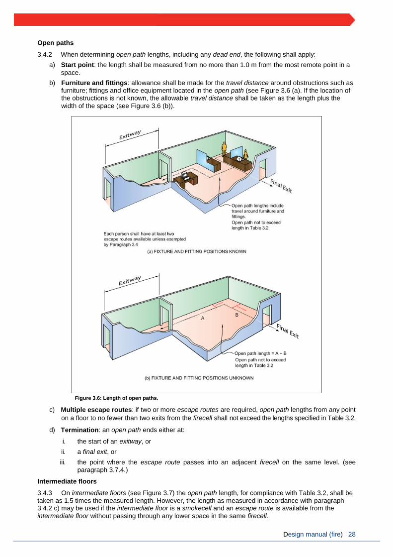
3.4.2 When determining open path lengths, including any dead end, the following shall apply:
a) Start point: the length shall be measured from no more than 1.0 m from the most remote point in a
space.
b) Furniture and fittings: allowance shall be made for the travel distance around obstructions such as furniture; fittings and office equipment located in the open path (see Figure 3.6 (a). If the location of the obstructions is not known, the allowable travel distance shall be taken as the length plus the
width of the space (see Figure 3.6 (b)).
Figure 3.6: Length of open paths.
c) Multiple escape routes: if two or more escape routes are required, open path lengths from any point
on a floor to no fewer than two exits from the firecell shall not exceed the lengths specified in Table 3.2.
d) Termination: an open path ends either at:
i. the start of an exitway, or
ii. a final exit, or
iii. the point where the escape route passes into an adjacent firecell on the same level. (see paragraph 3.7.4.)
Intermediate floors
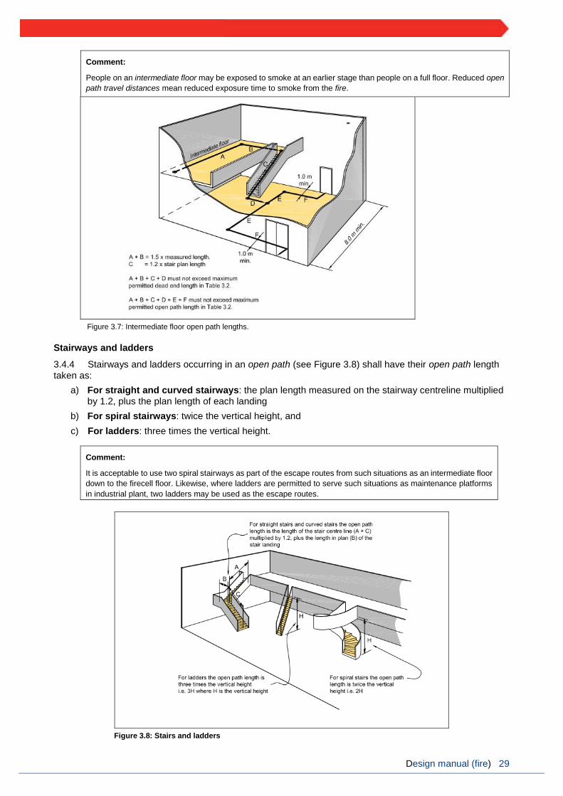
3.4.3 On intermediate floors (see Figure 3.7) the open path length, for compliance with Table 3.2, shall be taken as 1.5 times the measured length. However, the length as measured in accordance with paragraph 3.4.2 c) may be used if the intermediate floor is a smokecell and an escape route is available from the intermediate floor without passing through any lower space in the same firecell.
Design manual (fire) 29
Comment:
People on an intermediate floor may be exposed to smoke at an earlier stage than people on a full floor. Reduced open
path travel distances mean reduced exposure time to smoke from the fire.
Figure 3.7: Intermediate floor open path lengths.
Stairways and ladders
3.4.4 Stairways and ladders occurring in an open path (see Figure 3.8) shall have their open path length
taken as:
a) For straight and curved stairways: the plan length measured on the stairway centreline multiplied
by 1.2, plus the plan length of each landing
b) For spiral stairways: twice the vertical height, and
c) For ladders: three times the vertical height.
Comment:
It is acceptable to use two spiral stairways as part of the escape routes from such situations as an intermediate floor
down to the firecell floor. Likewise, where ladders are permitted to serve such situations as maintenance platforms
in industrial plant, two ladders may be used as the escape routes.
Figure 3.8: Stairs and ladders

Design manual (fire) 30
Escape through adjoining building
3.4.5 Due to the requirement to remain operational following a disaster, escape via an adjacent building is not allowed for.
3.5. Escape from basements
3.5.1 Except in cases where there are two or more escape routes serving only the basement firecells, and each escape route terminates in a safe place, safe paths serving basement firecells shall be preceded by a smoke lobby that shall have a plan area in accordance with paragraph 3.9.2.
Single escape routes
3.5.2 A single escape route and final exit is acceptable from basements (see Figure 3.9) where, in addition to the requirements of paragraph 3.13.1 and the smoke lobby requirements of paragraph 3.5.1, there are no more than two basement floor levels.
Comment:
Because fire safety systems are increased with increases in escape height, the precautions for basements increase
with basement depth. Thus a single floor building with one basement level is treated as a two floor building and a
single floor building with three basement levels as a four floor building.
Figure 3.9: Single escape routes from basement levels
3.6. Open paths
Number and size
3.6.1 Open paths shall satisfy the specific requirements of paragraphs 3.6.2 to 3.7 where they apply to a particular building.
Open path separation
3.6.2 If two or more open paths are required, they shall be separated from each other, and remain separated until reaching an exitway or final exit (see Figure 3.10). Separation shall be achieved by diverging (from the point where two escape routes are required), at an angle of no less than 90° until separated by:

Design manual (fire) 31
a) a distance of at least 8.0 m, or
b) smoke separations and smoke control doors.
Comment:
If this separation or protection is not provided, the length of the open path is limited to that of a dead end. This is
critical in planning single stairway buildings, as the stairway must be positioned within the dead end travel distance
limits.
Figure 3.10: Open path separation
3.7. Special cases for open paths
Ramps
3.7.1 Where stairways are not used, changes in level on an escape route shall be formed as ramps and
shall comply with Acceptable Solution D1/AS1 or NZS 4121.
Separate tenancy
3.7.2 This design manual does not allow for escape via a separate tenancy.
Open paths via unenclosed stairways.
3.7.3 Unenclosed stairways (stairways which are not smoke or fire separated from other spaces) in escape routes, shall not exceed a height of 4.0 m within the firecell. Where the height exceeds 4.0 m, the escape route from that level shall be a safe path until it reaches a final exit

Design manual (fire) 32
Passing into an adjacent firecell
3.7.4 An open path may pass into an adjacent firecell on the same level (see Figure 3.11) and recommence as a new open path provided that:
a) all firecells on the escape route have no fewer than two directions of escape, separated as required
by paragraph 3.6.2, and
b) adjacent firecells into which evacuation may take place have a floor area sufficient to accommodate
not only their own occupants but also the occupants from the adjacent firecell. This shall be
calculated on the basis of the occupant load of the two firecells, and
c) each firecell has at least one other escape route independent of the route into the adjacent firecell.
This other route may be by way of a final exit or using a third firecell provided that the exit from the
third firecell is independent of exits from the other two firecells, and
d) the escape route does not pass through more than three fire separations before entering an exitway
or final exit, and
e) the escape route width meets the requirements of paragraph 3.3.2 for the firecell on the escape
route that has the greatest occupant load.
Comment:
Open path lengths in each firecell are controlled by the requirements of paragraph 3.4.2 for that firecell.
Refer to paragraph 3.14.3 to determine if doors between firecells need to swing both ways to allow for
escape in both directions and paragraph 3.14.8 for hold-open device requirements.
Figure 3.11: Open path passing into an adjacent firecell.
Escape via an intermediate floor
3.7.5 An open path may pass from a firecell to an intermediate floor and recommence as an open path provided that:
a) where two or more escape routes are required from that firecell, only one escape route shall be via the intermediate floor, and
b) the intermediate floor is served by at least two escape routes, separated as required by paragraph
3.6.2 and terminates at separate firecells, exitways or final exits at the same level as the
intermediate floor, and
c) the intermediate floor open path lengths shall not exceed the requirements of paragraph 3.4.

Design manual (fire) 33
3.8. Dead ends
No more than 50 occupants
3.8.1 A dead end shall not serve an occupant load greater than 50.
Ladders
3.8.2 The escape route from a dead end may be a ladder complying with Acceptable Solution D1/AS1 if it serves only a support function or provides the same function in support of other risk groups and only if the occupant load does not normally exceed four. Ladders are not permitted as escape routes in any other circumstances (see also paragraph 3.4.4).
3.9. Exitways
3.9.1 Exitways consist of smoke lobbies and safe paths.
Smoke lobby floor area
3.9.2 If a smoke lobby is required to precede a vertical safe path (see paragraph 3.5.1 and Figure 3.12), its floor area shall be calculated for the occupant load for that smoke lobby by assuming that:
a) part of the occupant load will be accommodated in the stairway vertical safe path between the level being considered and the next level in the direction of escape, with the remaining occupants accommodated in the smoke lobby, and
b) the occupant density used to calculate the required holding area is 0.25 m2 per person in the stairway. The floor area shall include the area of the first landing, the plan area of the flights of stairs between the two floor levels, and the area of any intermediate landings. Additional space shall be provided for door swings.
Comment:
This paragraph does not include a requirement for a smoke lobby but if required by other parts of this design
manual, this paragraph states how smoke lobbies are to be sized.
Figure 3.12: Sizing of smoke lobbies
Safe paths
3.9.3 Except where the conditions for escape via successive open paths (see paragraph 3.7.4) apply escape routes from firecells shall enter directly into an exitway or final exit.
3.9.4 Safe paths shall be separated from each other and from all spaces by:

Design manual (fire) 34
a) fire separations, or
b) distance or appropriate construction if they are external to the building (see paragraph 3.11).
3.9.5 Except where the conditions for escape using an external escape route (see paragraph 3.11) or successive open paths (see paragraph 3.7.4) apply, exit doors from sleeping area firecells shall open directly onto:
a) a horizontal safe path, or
b) a final exit.
Safe path length restrictions
3.9.6 There is no limit on the length of a vertical safe path. Horizontal safe paths shall be no longer than specified in Table 3.4.
Safe path termination
3.9.7 Horizontal safe paths shall terminate at any of the following:
a) The entrance to an internal stairway which is a separate safe path, or
b) An external balcony leading to either an open or enclosed stairway, or
c) An opening in an external wall which enters on to a bridge leading to an open or enclosed stairway,
or
d) A final exit.
Comment:
Long safe path corridors may be required to be subdivided by smoke separations (see paragraph 4.10).
Number of directions Type 3 system Type 6 or 7 system
Single 35 m 40 m
Two or more 180 m Unlimited
Table 3.4: Travel distance on horizontal safe paths
Safe path separation and glazing
3.9.8 The vertical and horizontal portions of internal safe paths shall be separated at every floor level by fire separations and fire doors with smoke control capability.
3.9.9 Glazing in safe paths shall comply with the requirements of paragraph 4.2.
3.10. Control of exitway activities
3.10.1 Exitways shall not be used for:
a) storage of goods, solid waste or solid waste containers, or
b) entry points to solid waste chutes, or
c) the location of furniture or other combustibles, or
d) storage of clothing or linen, or
e) a cleaner’s cupboard not fire separated from the exitway, or
f) the location of an electrical switchboard or similar, or
g) any activity (other than as permitted by paragraph 3.10.2).
3.10.2 Some activities are permitted in an exitway if:
a) an alternative escape route is available from all firecells served by the safe path in which the
activities occur, and
b) the escape route is not impeded by the activity or the occupants involved in that activity, and

Design manual (fire) 35
c) those activities:
i. are visible to users of the exitway, except in the case of sanitary fixtures
ii. exist only to provide support functions to the activities of the risk group served by the exitway,
and
iii. include, but are not limited to, a reception counter and toilet facilities.
Lifts
3.10.3 A passenger lift but not a goods lift may be located in a vertical safe path containing a stairway provided the following conditions are satisfied:
a) the lift shaft and all its openings are located entirely within a single firecell containing the vertical safe path, and
b) passenger access into and from the lift takes place entirely within the safe path, and
c) no other activity occurs within the vertical safe path, and
d) the lift machine room is a separate firecell and the openings for lift ropes through the fire separation are as small as practicable and any penetrations, such as for electrical cables, are fire stopped. (See paragraph 4.4 for more information about fire stopping.)
Lift landings located in open paths
3.10.4 Lift landings located in open paths (see Figure 3.13) shall either be within a smokecell separated from all other areas or have lift landing doors with smoke control capability. This requirement does not apply if the firecell is protected with a Type 6 with supplementary smoke detection throughout or the lift shaft has a pressurisation system designed in accordance with AS 1668.1. Lift doors shall be as specified in paragraphs 4.14.3 and 4.14.11.
Figure 3.13: Lifts and smoke lobby on open paths.
3.11. External escape routes
3.11.1 Where an escape route enters a space exposed to the open air (e.g. an open stairway, a balcony, across a roof or a ground level path), it shall meet the requirements for a safe path between that point and the final exit. Safe path separation requirements shall be achieved by providing either distance or fire rated construction between the escape route and adjacent firecells, as specified in paragraphs 3.11.2 to 3.11.5.
Comment:
Balconies with one direction of escape comply with the requirements of a safe path if the external wall beside the
balcony has no unprotected areas or the balcony is large enough to allow separation by distance from the external
wall (see paragraph 3.11.2). Balconies with two directions of escape from all firecell exits are also considered to
be safe paths even if the adjacent external wall has 100% unprotected area.

Design manual (fire) 36
Separation by distance
3.11.2 Separation by distance shall be achieved by:
a) If there is only one direction of escape, roofs and external walls with no unprotected areas closer to an external escape route than:
i. 2.0 m if unsprinklered (see Figure 3.14), or
ii. 1.0 m if all firecells passed by the external escape route are sprinklered, or
Comment:
This provision is to limit the occupants’ exposure to radiant heat if they have only one direction of escape. The
separation distances shall be applied horizontally to both sides of the escape route.
b) positioning the escape route to ensure it diverges from external walls (see paragraph 3.11.4 a)), or
c) providing alternative directions of escape from the point where the escape route passes through an external wall and becomes an external escape route (see paragraph 3.11.4 b)).
Figure 3.14: External escape routes
3.11.3 If the distance separating external walls or roofs from an external dead end escape route is less than permitted by paragraph 3.11.2, those walls and roofs shall comply with the FRR requirements of paragraphs 5.3 and 5.7.3 to 5.7.5. Glazing shall comply with section 4.2.
3.11.4 For an escape route that passes through an opening in an external wall, the external wall does not have to be fire rated if:
a) the direction of escape to a single final exit diverges from the external wall at an angle of no less than 45° in plan, or
b) the directions of escape to alternative final exits diverge from each other at an angle of no less than 90° in plan and those directions of escape do not travel past any firecell for a distance of more than 5.0 m.

Design manual (fire) 37
Separation by fire rated construction
3.11.5 Except where the requirements for separation distances in paragraph 3.11.2 are achieved:
a) external walls and roofs adjacent to external escape routes shall comply with the FRR requirements in paragraphs 5.3 and 5.7 and shall have no unprotected areas except that glazing for safe paths
that complies with paragraph 4.2 is permitted, and
b) if the escape route is a balcony with a single direction of escape and the vertical distance between the underside of the balcony and the closest unprotected area in the external wall below is less than 5.0 m (see Figure 3.15), balcony barriers shall:
i. have no openings, and
ii. be protected with a material having a Group Number of no greater than 2, and
Comment:
See Appendix D for the method to assign a Group Number.
c) if the vertical separation between the undersides of an external escape route and unprotected areas in the external wall below is less than 5.0 m:
i. the floor of an external escape route closer to an external wall than required by paragraph
3.11.2 shall have an FRR of no less than required by paragraph 2.3, and
Comment:
If the escape route is a balcony with two directions of escape, the external wall need not be a fire separation and
the requirements for the floor of the balcony c) i) and the balcony b) do not apply.
ii. treads and risers of stairways on external escape routes shall either be constructed from a
material with a critical radiant flux of no less than 2.2 kW/m² or shall be protected on the
underside with a material having a Group Number of no greater than 2, and
d) If the escape route comprises external horizontal and internal vertical safe paths, a smoke separation
shall be provided between them.
Ventilation openings
3.11.6 The open area of a balcony or bridge shall be no less than 50% of the balcony floor area, and shall be evenly distributed along the open sides and any approach ramp (see Figure 3.15). Where an escape route on a balcony is served by an open stairway, similar ventilation shall be provided on the stairway. Open sides shall not be enclosed above a height of 1,100 mm from the floor, except that a fixed open grille may be used if it provides the required free air space.
Barriers
3.11.7 Changes in exitway floor level other than in the direction of travel shall have barriers that comply with Acceptable Solution F4/AS1.
Figure 3.15: Open balconies

Design manual (fire) 38
3.12. Final exits
3.12.1 Final exits which open onto the same safe place shall be spaced no closer than 5.0 m centre to centre. This applies to both internal and external exitways.
Comment:
This provision allows quick dispersal and reduces the risk of a crowd blocking a final exit.
3.13. Single escape routes
3.13.1 Single escape routes shall only be permitted if:
a) the open path length does not exceed the limits specified in Table 3.2, and
b) the total occupant load from all firecells on each level served by the escape route is no greater than 50, and
c) the escape height is no greater than:
i. 10 m if unsprinklered, or
ii. 25 m if sprinklered, and
d) unless the building is sprinklered and consists of two levels only, the vertical safe path is preceded by a smoke lobby on all floors except the topmost floor (refer to paragraph 3.9.2 for the sizing of the smoke lobby), and
e) there are no more than two basement levels below ground and the vertical safe path from the basement levels is preceded by a smoke lobby (see Figure 3.9).
3.13.2 A single escape route from sleeping area firecells is permitted provided that, in addition to the requirements of paragraph 3.13.1,:
a) the escape route within a sleeping area in each firecell terminates at a final exit or opens onto a safe path that complies with the requirements of paragraphs 3.9.4 to 3.9.11, and
b) the particular requirements for stairways, balconies and split level exitways, given in paragraphs 3.7.3 and 3.13.3, are satisfied, and
c) the length of any safe path on a floor does not exceed the maximum dead end length specified in Table 3.2Balconies, bridges and external stairways
3.13.3 Balconies, bridges and external stairways may be part of a single external escape route where:
a) the escape height is no greater than 16 m if unsprinklered or 25 m if sprinklered, and
b) the escape route on the balcony, bridge or stairway meets the requirements of paragraph 3.11 for protection, construction and ventilation, and
c) the length of any bridge between the external wall and stairway is no less than 3.0 m.
3.14. Doors subdividing escape routes
3.14.1 Except as permitted by paragraph 3.14.6 (automatic doors and access control systems), doors on escape routes shall satisfy the following requirements:
a) They shall be hinged or pivoted on one vertical edge only, except that sliding doors may be used where the space, including an exitway, has an occupant load of less than 20. Roller shutter doors or tilt doors shall not be used as an escape route except in an intermittently occupied space where the roller shutter door is the only access route and is open at all times the space is occupied, and
b) Fire and smoke control doors shall be self-closing and the self-closing device shall either be:
i. active at all times, or
ii. activated by releasing a hold-open device in response to operation of a smoke detector (see
paragraph 3.14.9), or
iii. a self-closer that is activated by operation of a smoke detector but allows the door to swing freely at other times. The smoke detector requirements shall be the same as for a hold-open device (see paragraph 3.14.9), and
c) If such doors are required to be secure, they shall be fitted with simple fastenings that are readily operated from the direction of approach used by people making an escape to comply with paragraph 3.14.11, and
d) They shall not be fitted with any locking devices unless they comply with paragraph 3.14.2, and

Design manual (fire) 39
e) They shall have door handles that satisfy the requirements of Acceptable Solution D1/AS1 or NZS 4121 for use by people with disabilities, and
f) They shall be constructed to ensure that the forces required to open these doors do not exceed those able to be applied:
i. with a single hand to release the latch (where fitted), and
ii. using two hands to set the door in motion, and
iii. using a single hand to open the door to the minimum required width.
Comment:
These requirements are based on the force requirements of Appendix C C6.1.3.
Locking devices
3.14.2 If the building is occupied, locking devices shall:
a) be clearly visible, located where such a device would be normally expected and, in the event of fire, designed to be easily operated without a key or other security device and allow the door to open in the normal manner.
b) If the operation of a locking device is unusual, such as the pressing of a button adjacent to the door, it shall have signage that complies with NZBC F8.3.1, and
Comment:
Examples of unacceptable locking or security devices are card access and keypad locks that are not interfaced
with the fire alarm and detection systems.
c) if they are of an electromechanical type, they shall, in the event of a power failure or door malfunction be readily opened by a method satisfying the requirements of paragraph 3.14.2 a), and
d) not prevent people in vertical safe paths from entering other floors.
Comment:
One way to comply with paragraph 3.14.2 is to develop a building management plan.
A building management plan procedure must be approved by the building consent authority and should include a
provision to ensure that all escape route doors are unlocked when anybody is lawfully in the building.
This design manual does not prevent the NZFS, for security purposes, from locking escape route doors when the
building is unoccupied.
People escaping down a stairway have to be able to move from one stairway to another using a horizontal safe
path corridor so that, if one stairway becomes smoke-logged or unusable for any reason, people can continue their
escape using an alternative route. If the stairway is a single means of escape, people will still need to move out of
the stairway and wait for rescue by emergency services within a floor.
Direction of opening
3.14.3 Doors on escape routes shall be hung to open in the direction of escape. However, this is not required if there is not more than 50 occupants using the door for egress. If escape can be in either direction, doors shall swing both ways. For manual sliding doors, see paragraph 3.14.1.
Degree and width of opening
3.14.4 Doors on escape routes (see Figure 3.16) shall satisfy the following requirements:
a) in open paths, provide an unobstructed opening width of no less than 760 mm and if multi-leaf, have no single leaf width of less than 500 mm, and
b) within exitways (including entry and final exit doors), reduce the minimum exitway width required by paragraph 3.3 by no more than the 125 mm allowed in paragraph 3.3.5 c) to 875 mm, and
c) open no less than 90°, and
d) open onto a floor area which:
i. extends for a distance of no less than the arc of the door swing, and
ii. is at the same level on both sides of the door for the full width of the escape route, and

Design manual (fire) 40
Comment:
A 20 mm threshold weather-stop is acceptable on external doors (see Acceptable Solution D1/AS1).
Figure 3.16: Degree and width of openings
e) when opened, not cause the door swing to obstruct the minimum required width of any escape route.
For example, doors which open onto a corridor used as an escape route shall not obstruct the minimum
required width of that escape route (see Figure 3.17).
Figure 3.17: Door opening

Design manual (fire) 41
Vision panels
3.14.5 Vision panels shall be provided on doors which:
a) are hung to swing both ways, or
b) lead into or are within exitways that swing in the direction of escape, or
c) subdivide corridors used as escape routes.
Automatic doors
3.14.6 Automatic doors (of all types) shall:
a) not be allowed across an escape route at any point leading into or within an exitway, but
b) be allowed in an open path or at a final exit, provided that in the event of a power failure or malfunction, the doors continue to provide a safe means of escape from fire without reducing the
required width by:
i. automatically opening and remaining open, or
ii. being readily pushed to the outward open position by the building occupants in an
emergency (refer to Figure 3.18).
Comment:
Revolving doors and access control systems will not normally be present in fire stations.
The requirements in ii) are based on the force requirements specified in Appendix C C6.1.3.
Figure 3.18: Automatic sliding doors
3.14.7 Paragraph 3.14.6 b) need not apply if alternative swing doors of the required width are provided immediately adjacent to the revolving or sliding doors. See paragraph 3.15 for signage requirements.
Hold-open devices
3.14.8 Detector activated hold-open devices shall be fitted to fire doors or smoke control doors required:
a) between open paths and exitways if the occupant load is greater than 1,000, and
b) for subdividing long corridors (see paragraph 4.10), and

Design manual (fire) 42
c) in fire separations where an escape route passes into an adjacent firecell (see paragraph 3.7.4), and
Comment:
An example of c) would be between a horizontal safe path or smoke lobby and a vertical safe path.
d) In some locations due to the type or volume of occupant traffic using the doors, the doors may be kept open by unauthorised means.
Comment:
Hold-open devices are used where it is not practical to assume that fire doors and smoke control doors will remain
closed because of the type or volume of occupant traffic using these doors. The devices should eliminate the
unsafe practice of wedging or otherwise keeping self-closing doors open.
For the convenience of building occupants, it is often useful to provide a clearly-labelled push-button release
adjacent to doors that have hold-open devices.
3.14.9 Detectors for releasing hold-open devices shall be smoke detectors which are:
a) Integral with the hold-open device and comply with Appendix C, or
b) Located on the ceiling adjacent to the doorset on both sides of the doorset, or
c) Part of an automatic smoke detection system on both sides of the doorset.
Delayed action unlocking devices and access control systems
3.14.10 This design manual does not allow for delayed action unlocking devices and access control systems.
Simple fastenings
3.14.11 Doors on escape routes (whether or not the doors are fire doors) shall be fitted with simple fastenings that can be easily operated from the direction from which people approach when making their escape.
Comment:
This generally excludes the use of keyed locks and bolt fastenings. See paragraph 3.14.2 for security and safety.
3.15. Signs
3.15.1 All escape routes, fire doors and smoke control doors shall have signs complying with NZBC F8.

Design manual (fire) 43
4. Control of internal fire and smoke spread
4.1. Firecells
4.1.1 Firecells shall be fire separated from each other by the life rating specified in paragraph 2.3 of this manual (60 minutes for unsprinklered buildings and 30 minutes for sprinklered buildings).
The appliance bay and supporting spaces shall be a separate smokecell. Supporting activities include all spaces providing direct support to the operational response. These include the watch room, muster bays and BA compressor rooms where required.
Refer to paragraph 4.6 for the requirements of sleeping accommodation areas.
Comment:
In some existing stations this may also include some offices or meeting rooms.
4.2. Glazing in fire and smoke separations
4.2.1 Glazing in fire separations shall be fixed fire resisting glazing having the same FRR values for integrity and insulation as the fire separation. This does not apply where uninsulated glazing is permitted within vision panels and for sprinklered buildings. 4.2.2 Uninsulated fire resisting glazing that has the same integrity value as the fire separation is permitted in fire separations in sprinklered buildings and in external walls in accordance with paragraph 5.4. 4.2.3 There is no restriction on the area of glazing in smoke separations (including smoke lobbies). Non-fire resisting glazing may be used if it is toughened or laminated safety glass. Glazing shall have at least the same smoke-stopping ability as the smoke separation.
Fire doors and smoke control doors
4.2.4 Glazing in fire doors shall be fire resisting glazing having the same integrity value as the door. If the door requires an insulation value, an uninsulated vision panel may be used without downgrading the insulation value of the door. Vision panels shall comply with NZS 4520. 4.2.5 Glazing in smoke control doors shall meet the requirements for smoke separations.
4.3. Structural stability during fire
Stability of building elements that have an FRR
4.3.1 To avoid premature failure, this manual requires the structural stability of primary building elements, with an FRR to be retained for the duration of that FRR. Primary elements located entirely within a firecell and providing support to fire separations may need to be simultaneously evaluated for fire exposure from
multiple sides.
Comment:
This situation arises when a primary element, such as a column or wall, located entirely within a firecell provides
lateral support to a firecell boundary wall or vertical support to the firecell floor or ceiling. Results against the
standard furnace tests for fire resistance may not be suitable as they commonly relate to exposure from one side
only. Separate evaluation is required to assess the performance of primary elements when simultaneously
exposed to fire from more relevant sides.
4.3.2 During a fire, primary elements shall resist collapse under:
a) the design dead and live loads required by NZBC B1, and
b) any additional loads caused by the fire.

Design manual (fire) 44
Comment:
NZBC B1.3.3 (c) and (i) requires that structural stability accounts for vertical and horizontal loads, temperature
and fire effects.
Additional loadings can arise from changes in length or other deformations in building elements as a result of
high temperatures.
Yield strength of most materials generally reduces with temperature increase so that strength reduction is related
to the time for which the primary element is exposed to fire. Factors which need to be taken into account include
the maximum temperature attained, the capacity of the element to absorb heat, potential loss of section, the
degree of exposure, whether any applied coating is used to protect the element from the effects of fire, and the
degree of restraint provided by the surrounding structure.
Unrated primary elements
4.3.3 In many cases, primary elements are rated for structural adequacy and sometimes for integrity and insulation. However, primary elements need not have an FRR where any of the following circumstances
exist:
a) They are located outside an external wall which is 2.0 m or more from the relevant boundary, and are shielded from the effects of fire by protected areas of the wall (see Figure 4.1).
b) They are added to strengthen an existing building and are required only to carry horizontal loads induced by wind or earthquake.
Providing vertical stability
4.3.4 Building elements that require an FRR shall have their vertical stability provided in one or more of
the following ways:
a) Primary elements in a vertical orientation (e.g., walls and columns) shall be rated for structural adequacy.
b) Primary elements in a horizontal orientation (e.g., floors and beams) shall be supported by primary elements with at least an equivalent structural adequacy rating.
Providing horizontal stability
4.3.5 Building elements that require an FRR shall have their horizontal stability provided in one or more of
the following ways:
a) Be cantilevered from a structural base having an FRR of no less than that of the building element
concerned.
b) Be supported within the firecell by other building elements having an FRR no less than that required for the element being supported. The structural adequacy and diaphragm action of supporting building elements located entirely within a single firecell must be assessed when exposed to fire from
all relevant sides simultaneously.
c) Be supported by primary elements outside the firecell.
Figure 4.1: Permissible positioning of unrated primary elements

Design manual (fire) 45
Comment:
It is assumed that fire will be restricted to the firecell of origin at least for the time required by the property rating
of the primary element concerned.
The stability of a beam or fire separation may, for example, be provided by beam or diaphragm action of a floor
or wall which is rated only for structural adequacy.
A standard test for fire resistance commonly exposes fire separations from one side only and may not be a
suitable measure for determining the structural adequacy of a building element when simultaneously exposed
to fire from more than one side.
4.4. Fire stopping
Introduction
4.4.1 The continuity and effectiveness of fire separations shall be maintained around penetrations and in gaps between or within building elements, by the use of fire stops. 4.4.2 Fire stops shall have an FRR of no less than that required for the fire separation within which they are installed, and shall be tested in accordance with Appendix C 5.1. 4.4.3 Fire stops and methods of installation shall be identical to those of the prototype used in tests to establish their FRR.
4.4.4 The material selected for use as fire stops shall have been tested for the type and size of the gap or penetration, and for the type of material and construction used in the fire separation.
Comment:
There are many types of fire stops (e.g., mastics, collars, or pillows) that are designed to suit specific situations.
A fire stop is appropriate for a particular application if it passes the test criteria when installed as specified.
4.4.5 A fire stop for a penetration is not required to have an insulation rating if a method is used to prevent ignition by keeping combustible materials at least 300 mm away from the penetration and fire stop.
4.5. Firecell construction
4.5.1 Each of the building elements enclosing a firecell is permitted to have a different FRR, as this rating will depend on the characteristics of the firecell, the reason for the FRR and the risk groups contained on either side of any fire separation.
Comment:
An FRR of zero may apply to some walls and most roofs.
4.5.2 Except where intermediate floors are permitted, each floor in a multi-storey building shall be a fire separation.
4.5.3 Fire and smoke separations shall have no openings other than:
a) for closures such as doorsets, and
b) penetrations that comply with paragraph 4.4, and
c) for glazing permitted by paragraph 4.2.
4.5.4 Firecell and smokecell effectiveness shall be maintained by ensuring continuity of fire and smoke separations at separation junctions and around joints where closures, protected shafts and penetrations
occur.
Fire separation junctions
4.5.5 Where fire separations meet other fire separations or fire rated parts of external walls, they shall either be bonded together or have the junction fire stopped over its full length (see Figures 4.2 and 4.3)

Design manual (fire) 46
4.5.6 Where one fire separation is a wall and the other a floor, the wall or floor junction shall be constructed with the FRR required for the higher rated element.
Roof junctions
4.5.7 Vertical fire separations and external walls shall either:
a) terminate as close as possible to the external roof cladding and primary elements providing roof support and ensure all gaps are fully fire stopped (see Figures 4.2 and 4.3), or
b) extend not less than 450 mm above the roof to form a parapet.
c)
Figure 4.2: Fire separation junctions -1

Design manual (fire) 47
Figure 4.3: Fire separation junctions -2
Ceiling space firecells
4.5.8 Large roof or ceiling spaces may be constructed as separate firecells above more than one occupied firecell provided that the ceiling is a fire separation rated from below. In this situation, vertical fire separations in the firecell below need terminate only at the ceiling.
Sealing of gaps
4.5.9 To avoid the passage of smoke through fire and smoke separations, gaps shall be sealed with fire
resistant materials complying with AS 1530.4 in their intended application if they are located:
a) in smoke separations, and between smoke and fire separations
b) around glazing in smoke separations
c) between fire or smoke separations and unrated parts of external walls.
4.5.10 Gaps around penetrations shall be fire stopped (see section 4.4).
4.6. Specific requirements for sleeping area firecells
4.6.1 A sleeping area may be subdivided into separate suites. Each suite shall be a separate firecell and contain no more than 12 beds. Fire separations between adjacent suites on the same floor level shall have an FRR in accordance with paragraph 2.3. 4.6.2 Intermittently occupied spaces, such as tea bays and sanitary facilities, which provide direct support functions to the sleeping area may be included in a sleeping area firecell.
4.6.3 Spaces such as storerooms, laundry facilities, communal kitchens, dining rooms, lounges and meeting spaces shall be separated from sleeping area firecells with fire separations having an FRR in accordance with paragraph 2.3. It is acceptable for these non-sleeping areas to share a common firecell.
4.7. Exitways
4.7.1 Exitways, unless external and separated by distance, shall comprise smoke lobbies in accordance with paragraph 3.9.2 and/or safe paths which are firecells.
4.7.2 The safe path shall be separated from all adjoining firecells by fire separations with an FRR in accordance with paragraph 2.3 throughout its length. If the escape height is greater than 10 m, the fire separation shall have an FRR that meets the property rating.

Design manual (fire) 48
4.7.3 Safe paths which are stairways leading from lower floors or basements and which continue to floors above the level of the final exit, shall have the lower levels fire separated from the final exit level. The fire separation shall have an FRR in accordance with paragraph 2.3 or that required for the lower level, whichever is the greater.
4.7.4 Safe paths which are long corridors, shall be subdivided by smoke separations in accordance with paragraph 4.10.
4.7.5 Air ducts passing through exitways shall not include combustible materials.
4.8. Intermittent activities
Support activities
4.8.1 Intermittent activities providing direct support to the operational response (such as the BA compressor room, lockers and decontamination areas) do not require fire or smoke separation, unless they are provided for enclosed waste storage or car parking. The fire safety systems required for the station shall also apply throughout these spaces. If these spaces are required to be separate firecells, they shall have fire separations with FRRs in accordance with paragraph 2.3.
Solid waste storage
4.8.2 Solid waste storage areas shall be enclosed when located adjacent to occupied spaces. In other situations, these areas may be unenclosed. Enclosed solid waste storage areas within any firecell shall themselves be a separate firecell separated from adjacent firecells by fire separations having an FRR of no
less than 60 minutes (see paragraph 4.9.5 for waste chutes).
Plant, boiler and incinerator rooms
4.8.3 Any space within a building (see Figure 4.4) containing an incinerator, plant, boiler or machinery which uses solid fuel, gas or petroleum products as the energy source (but excluding space and local water heating appliances) shall be a separate firecell with an FRR of no less than 90 minutes, and shall have:
a) at least one external wall
b) external access from any floor level including the roof. Where alternative internal access is provided,
it shall be via a smoke lobby that is protected with a heat detector connected to a Type 2, 3 or 4 alarm
system, and
c) a floor level no lower than the ground level outside the external wall if gas is the energy source.
4.8.4 If a building has a sole purpose of containing plant and the building is separated by 3.0 m or more from any adjacent building, only paragraph 4.8.3 c) shall apply.
Figure 4.4: Plant, boiler and incinerator rooms

Design manual (fire) 49
4.9. Protected shafts
Lifts, conveyors and services
4.9.1 Lifts, conveyors and services which pass from one firecell to another shall be enclosed within protected shafts.
Comment:
Paragraph 3.10.3 describes the requirements for the installation of a passenger lift in a vertical safe path
containing a stairway. Paragraph 3.10.3 requires the vertical safe path to be a single firecell.
Fire separation
4.9.2 Every protected shaft shall be a separate firecell within the firecell or firecells in which it is located (see Figure 4.5). The shaft walls between each floor shall have an FRR of no less than that required by the life rating of the risk group for that level.
Comment:
The FRR of the shaft wall applies to both sides equally, except in the case of lift landing doors (see paragraph
4.14.11).
4.9.3 Protected shafts which do not extend through the roof or lowest floor shall be enclosed at the top and bottom by construction that satisfies the relevant requirements of paragraph 4.4 for fire stopping (see Figure 4.5).
Openings in protected shafts
4.9.4 There shall be no openings in protected shafts except for:
a) access panels that have an FRR of no less than that required for the shaft
b) doorsets that provide access to lifts and comply with smoke control requirements
c) openings for lift ropes passing into a lift motor room which shall be as small as practicable.
d) fire dampers serving a ventilation duct and complying with requirements for fire resisting closures.
e) penetrations which satisfy the fire stopping requirements contained in paragraph 4.4, or
f) fittings with a FRR of no less than that required for the protected shaft.
Figure 4.5: Protected shafts

Design manual (fire) 50
Solid waste and linen chutes
4.9.5 Solid waste and linen chutes which pass from one firecell to another shall be protected shafts or contained within a protected shaft. If the building is unsprinklered, each chute shall be equipped with automatic sprinkler heads connected to any water supply pipe capable of meeting the minimum design criteria for the selected sprinkler head. These sprinklers shall be installed at the top of each chute and in the space into which the chute discharges.
The minimum residual pressure in the water supply pipe shall be 50 kPa with two sprinkler heads operating.
Comment:
The minimum residual pressure requirement for any operating sprinkler ensures that sufficient flow rate and area
coverage is provided to control a fire.
4.9.6 Solid waste and linen chutes shall have no inlet or discharge openings within an exitway.
4.10. Long corridor subdivision
4.10.1 Long corridors shall be subdivided by smoke separations and smoke control doors (see Figure 4.6)
which shall be evenly spaced along the corridor and no further apart than:
a) 40 m within open paths, or
b) 80 m within safe paths.
These lengths may be increased by 50% if the building is sprinklered.
Comment:
The smoke control doors are to swing both ways if required by paragraph 3.14.3.
Hold-open devices are required by paragraph 3.14.8 to allow the doors to remain open during normal use of the
building but to close automatically in the event of a fire.
Figure 4.6: Long corridor subdivision.

Design manual (fire) 51
4.11. Floors
4.11.1 Floors in buildings shall be fire separations (see Figure 4.6) except if any of the following conditions
are satisfied:
a) the floor is an intermediate floor within a firecell (see paragraph 4.11.3 for the FRR requirement), or
b) the floor is the lowest floor above an unoccupied subfloor space, and complies with paragraph 4.12.1.
4.11.2 Floors only need to be rated from the underside (see Figure 4.6). The FRR of a floor shall have a rating applicable to the firecell directly below the floor.
Intermediate floors
4.11.3 Intermediate floors and stairways used as access and their supporting primary elements within the firecell shall have FRRs of at least 30 minutes. 4.11.4 Intermediate floors shall satisfy the following conditions:
a) if there are two or more separate intermediate floors, the levels of those floors above the firecell floor must not differ by more than 1.0 m, and
b) the total combined occupant load on the intermediate floors is not greater than 100, and
c) the total combined area of the intermediate floors is no greater than specified in paragraph 4.11.5
4.11.5 The total combined area of the intermediate floors within the firecell shall be the lowest of:
a) 20% of the area of the firecell floor, not including the area of the intermediate floors if the intermediate floors are enclosed or partitioned or
b) 40% of the area of the firecell floor, not including the area of the intermediate floors if the intermediate floors:
i. are completely open, or ii. if enclosed or partitioned, a Type 4 system is installed, or
c) the area that allows up to 100 occupants on the intermediate floors based upon the occupant
density of the space in accordance with paragraph 1.3.
Comment:
The smaller (20%) floor area is a concession for spaces used essentially for storage with a low occupant density.
Firecells containing intermediate floors require the same fire safety precautions as single level firecells having
the same total occupant load and escape height. As 100 occupants is the maximum occupant load of an
intermediate floor (depending on the activity on that floor), the area of that floor cannot exceed that necessary
to accommodate 100 persons.
Basement floors
4.11.6 Basement firecells shall be separated from one another, and from the lowest firecell above ground level, by fire separations having FRRs in accordance with paragraph 2.3.
4.12. Subfloor spaces
4.12.1 In buildings with an unoccupied subfloor space between the ground and lowest floor (see Figure 4.7), the FRR of that floor shall be in accordance with paragraph 2.3, except that no FRR is required if the
following conditions are satisfied:
a) vertical fire separations and external walls extend down to ground level and enclose the space, and
b) access is available only for intermittent servicing of plumbing, drainage or other static services, and
c) the space is not used for storage and does not contain any installation such as machinery or heating appliances which could create a fire hazard, except if it is fire separated from the rest of the subfloor
space.

Design manual (fire) 52
Figure 4.7: Subfloor spaces
4.13. Concealed spaces
4.13.1 The spread of fire in concealed spaces and cavities shall be avoided by ensuring that extensive voids do not pass from one firecell to another. Also, smaller voids must be blocked off using cavity barriers or, where appropriate, fire stops. See paragraph 4.4.
Comment:
This manual directs design solutions towards enclosing spaces with fire and smoke separations as a method of
controlling fire and smoke spread. However, if fire separations are internal walls, it is essential that those walls
enclose any upper concealed space by extending beyond the ceiling to the floor or roof above.
Smoke detection and alarm systems are often relied on to provide building occupants, particularly sleeping risk
groups, with early warning in the event of fire. However, where the smoke detectors are located only in occupied
spaces, smoke and fire can travel unobserved in upper concealed spaces that have not been fire or smoke
separated. See paragraph 4.13.2 for subdivision requirements for concealed spaces.
Concealed spaces within firecells
4.13.2 An upper concealed space may be used as an air handling plenum (see Figure 4.8) if the following
requirements are satisfied:
a) the upper concealed space does not extend into another firecell, and
b) the ceiling and its supports and surfaces within the concealed space are non-combustible, and
c) electrical wiring is supported clear of the ceiling members and other equipment, and
d) any material used, such as pipe insulation or acoustic insulation, complies with the requirements of Table 4.1, and
e) where the air handling plenum is used as an air supply path, detector activation causes the
ventilation system to switch from circulation to extract as required by paragraph 4.16.2.
Comment:
Paragraph 4.13.2 e) does not apply when the air handling plenum is used as an air exhaust path with a separate
ducted air supply to the firecell.

Design manual (fire) 53
Notes:
1. Type 4 system is required
2. If the plenum is used as an air supply path see paragraphs 4.13.2(e) and (f) for automatic fire detection
and alarm requirements.
3. If the firecell is required to have smoke control in the air handling system (FSP Type 9), see Appendix A
paragraph A2.1.2 for necessary fire detection and alarm systems.
Figure 4.8: Concealed spaces within firecells
Cavity barriers in walls and floors
4.13.3 Any concealed space which may be a path for fire spread within internal walls or floors which are fire separations, or within external walls, shall have cavity barriers or be fire stopped (see paragraph 4.4), at all
common junctions (see Figures 4.9 and 4.10).
Comment:
In multi-storey buildings, it is essential to avoid rapid vertical fire spread between floors. Paragraph 5.9.14 deals
with the particular requirement for external walls, where ‘curtain wall’ type construction may create extensive
cavities.
Exceptions to cavity barrier requirements
4.13.4 Cavity barriers are not required in the following circumstances:
a) Below a floor next to the ground if the concealed space is:
i. less than 1.0 m in height, or
ii. not normally accessed and has no openings through which rubbish can accumulate, or
b) If the concealed space results from the over-cladding of an existing external wall or roof, provided
that the existing cladding is non-combustible, or
c) In a wall or roof panel system encapsulated with a material having a Group Number no greater
than 2.

Design manual (fire) 54
Figure 4.9: Curtain wall.
Figure 4.10: Hollow construction.
Comment:
See Appendix D of this design manual for the method for assigning Group Numbers to materials.
Cavity barrier construction
4.13.5 Cavity barriers shall:
a) not reduce the FRR required for the element within which they are installed.

Design manual (fire) 55
b) where practical, be tightly fitted and mechanically fixed to rigid construction but if this is not possible gaps shall be fire stopped, and
c) be fixed in a way that avoids impairment of their fire separation function as a result of:
i. building movement due to subsidence, shrinkage or thermal change, or
ii. collapse or failure of their components or fixings, or of abutting materials and any penetrations during a fire.
4.14. Closures in fire and smoke separations
Introduction
4.14.1 If activities within a building require openings in fire or smoke separations (e.g., for the passage of people, goods or services, or light), closures to those openings shall have the fire resistance and smoke control performance as follows:
a) an FRR of -/60/30 sm if unsprinklered (except as permitted by paragraphs 4.14.11 and 4.14.12) or
b) An FRR of -/30/- sm if sprinklered.
Comment:
sm indicates that the closure performs as part of a smoke separation. See paragraph 4.14.2 b) for doors
in smoke separations and paragraph 4.14.10 for access panels.
4.14.2 Doorsets which are required to be:
a) fire doors shall comply with Appendix C C6.1.1
b) smoke control doors shall, except as allowed by paragraph 4.14.3, comply with Appendix C
C6.1.2, and
c) fire doors with smoke control capability shall comply with both a) and b).
Comment:
Smoke seals may be of the brush type and need not incorporate intumescent material. However, intumescent seals
may be required if the door is also a fire door.
4.14.3 Doorsets installed in fire separations between firecells and vertical safe paths or protected shafts
shall have smoke seals on all edges, except that smoke seals may be omitted:
a) at the sill of doorsets, and
b) for lifts, if either:
i. the firecell is sprinklered and has an automatic smoke detection system, or
ii. a smokecell is placed between the doors and the rest of the firecell, other than when the lift shaft is permitted to be in the vertical safe path.
Fire door and smoke control door installation
4.14.4 Fire doors and smoke control doors shall be installed in accordance with paragraph 3.14.
Doorset markings
4.14.5 Doorsets shall be clearly marked to show their FRR and, if required, to show their smoke stopping capability. Other signage requirements shall be as specified in paragraph 3.15. 4.14.6 Markings and labelling shall, in all other respects, comply with NZS 4520.

Design manual (fire) 56
Glazing in doors
4.14.7 Glazing in fire doors and smoke control doors shall comply with paragraph 4.2.
Smoke control doors
4.14.8 Smoke control doors complying with paragraphs 4.14.2 to 4.14.7 shall be provided:
a) at smoke control separations in vertical safe paths
b) where a corridor or an escape route passes through a smoke separation (see Figure 4.11 and
for long corridors Figure 4.6), and
c) between an open path and a smoke lobby (see Figures 4.12 and 4.13).
Figure 4.11: Smoke control doors.

Design manual (fire) 57
Figure 4.12: Smoke control doors in smoke lobbies.
Figure 4.13: Fire doors and smoke control lobbies.

Design manual (fire) 58
Fire doors
4.14.9 Fire doors shall be provided:
a) between an open path and a safe path (see Figures 3.12 and 4.14)
b) between a smoke lobby and a safe path (see Figure 4.13)
c) where the escape route passes through a fire separation (see Figure 4.14)
d) where the escape route passes through a fire separation which isolates the safe path from levels below the final exit (see Figure 4.14), and
e) in fire separations between vertical and horizontal portions of internal safe paths.
Comment:
Doors at final exits are not required to be fire rated.
Fire doors in exitways protect occupants from the effects of fire during evacuation. Fire doors at the head of
stairways to basements, as required by paragraph 4.7.3, isolate the basement section of the vertical safe path.
Protected shaft access panels
4.14.10 Access panels to protected shafts shall have the fire resistance performance as required by
paragraph 4.13.2 and shall:
a) be capable of being opened only with a special tool, and
b) if smoke seals cannot be provided, be tight-fitting with a maximum total gap of 8 mm around the
panel (see Figure 4.16).
Figure 4.14: Fire doors

Design manual (fire) 59
Figure 4.15: Fire doors to separate floors above and below final exit level.
Lift landing doors
4.14.11 Other than where paragraph 3.10.3 for a passenger lift within a vertical safe path applies, doorsets for lift landing doors opening into lift shafts are protected shafts that shall be fire doors. These fire doors shall comply with paragraphs 4.14.1 to 4.14.3 except that an insulation rating is not required. Lift landing doors need not be fire rated from the shaft side.

Design manual (fire) 60
Figure 4.16: Access panels
Fire dampers
4.14.12 Any duct (unless fully enclosed by construction with an FRR no less than required for the fire separation) that passes through a fire separation shall not reduce the fire resistance of the construction (excluding external walls and roofs through which the duct passes.
Where a fire damper is used to maintain the required fire resistance it shall:
a) comply with AS/NZS 1668.1, and
b) have a fire integrity and insulation rating no less than that of the fire separation, except that the damper
blade is not required to have an insulation rating if the building is sprinkler protected or means are
provided to prevent combustible materials being placed closer than 300mm to the fire damper and air
duct.
The fire damper shall be capable of being readily accessed for servicing.
Fire shutters
4.14.13 If a floor has a service opening (e.g., for stairways, a conveyor, forklift access or similar installation) which is not used as part of an escape route and which is fitted with a fire shutter, the floor may be treated as a fire separation.
4.14.14 The fire shutter shall be automatically activated by a signal from a smoke detector.
4.14.15 A fire shutter shall include a device to retard the rate of closing to no more than 150 mm/second.
4.15. Interior surface finishes, floor coverings and suspended flexible fabrics
Surface finish requirements for walls, ceilings, ducts and insulation
4.15.1 Surface finish requirements shall be as specified in Table 4.1.

Design manual (fire) 61
Maximum permitted Group Number
System type Exitways (all occupied spaces)
Ducts for HVAC systems: internal surfaces
Ducts for HVAC systems: external surfaces
Acoustic treatment and pipe insulation within air handling plenum
Unsprinklered 1S 1S 3 3
Sprinklered 2 2 3 3
Table 4.1: Surface finish requirements
Comment: The method for assigning the Group Number to a material and for establishing the smoke production rate is specified in Appendix D. This may also be used when assessing existing buildings. Particular note should be made of the requirements for ducts. There are also instances of certain surface finishes being assigned Group Numbers without evaluation e.g. films and paint coatings.
Foamed plastics and exposed combustible insulating materials
4.15.2 If foamed plastics building materials or exposed combustible insulating materials form part of a wall, ceiling or roof system, the complete system shall achieve a Group Number as specified in Table 4.1. The foamed plastics shall comply with the flame propagation criteria as specified in AS 1366 for the material being used. This requirement does not apply to the building elements listed in paragraph 4.15.6.
Comment:
The completed system may or may not include a surface lining product enclosing any insulation material from any
adjacent occupied space. If a surface lining is not included, then the foamed plastics or combustible insulating
materials when tested alone shall achieve a Group Number of 3. Otherwise a surface lining is also required such
that the completed system achieves a Group Number of 3. This paragraph applies to foamed plastics building
materials whether exposed to view from the occupied space or enclosed.
Flooring
4.15.3 Flooring shall be either non-combustible or, when tested to IS0 9239-1, shall have a critical radiant flux of not less than that specified in Table 4.2. 4.15.4 Paragraph 4.15.3 shall apply to flexible finishes such as carpets, vinyl sheet or tiles and to finished or unfinished floor surfaces.
Wood and wood products in floors
4.15.5 In any firecell which has a firecell below, the flooring may be of wood products (wood products include boards manufactured from wood fibres or chips bound by an adhesive). Also, the floor must have either a thickness of no less than 20 mm or the floor assembly has an FRR of -/30/30 when exposed to fire from the flooring side.
Area of building
Minimum critical radiant flux when tested to ISO 9239-1
Fire sprinkler system not installed
Fire sprinkler system installed
Exitways in all buildings 2.2 kW/m² 2.2 kW/m²
Firecells accommodating more than 50 people
2.2 kW/m² 1.2 kW/m²
All other occupied spaces 1.2 kW/m² 1.2 kW/m²
Table 4.2: Critical radiant flux requirements for flooring

Design manual (fire) 62
Exceptions to surface finish requirement
4.15.6 Surface finish requirements do not apply to:
a) small areas of non-conforming product within a firecell with a total aggregate surface area of not
more than 5.0 m2.
b) electrical switches, outlets, cover plates and similar small discontinuous areas
c) pipes and cables used to distribute power or services
d) handrails and general decorative trim of any material such as architraves, skirting and window components, including reveals, provided these do not exceed 5% of the surface area of the wall or ceiling they are part of
e) damp-proof courses, seals, caulking, flashings, thermal breaks and ground moisture barriers
f) timber joinery and structural timber building elements constructed from solid wood, glulam or laminated veneer lumber. This includes heavy timber columns, beams, portals and shear walls not more than 3.0 m wide but does not include exposed timber panels or permanent formwork on the underside of floor/ceiling systems
g) individual doorsets, and
h) continuous areas of permanently installed openable wall partitions having a surface area of not more than 25% of the divided room floor area or 5.0 m2, whichever is less.
Suspended flexible fabrics
4.15.7 When tested to AS 1530 Part 2, suspended flexible fabrics shall, within all occupied spaces including exitways:
a) have a flammability index of no greater than 12, and
b) when used as underlay to roofing (whether or not the space is sprinklered) or exterior cladding that is exposed to view, have a flammability index of no greater than 5.
Membrane structures
4.15.8 The fabric of structures such as canopies shall be tested to AS 1530 Part 2 and shall achieve a flammability index of no greater than 12.
Air ducts
4.15.9 Where air ducts are contained wholly within a protected shaft, provided the shaft does not also contain lifts, only the interior surface finish of the air duct is required to comply with Table 4.1.
4.16. Building services plant
Automatic activation
4.16.1 When any smoke detection system is activated, it shall automatically turn off all air-conditioning and mechanical ventilation plant which is not required or designed for fire safety.
Air handling systems
4.16.2 Where smoke control in air handling systems is required to prevent the recirculation of smoke through an air handling system to other firecells in a building, these systems shall be as specified in Appendix A,
A2.1.

Design manual (fire) 63
5. Control of external fire spread
5.1. Fire separation for buildings with more than one title
5.1.1 When a building is subdivided so that the building straddles more than one title, each part of the building located on a separate title, other than titles comprising vehicle parking areas, shall be separated from:
a) The part of the building on an adjacent title, by fire separations having an FRR meeting the property rating in accordance with paragraph 2.3, and
b) Any external area in common (unless paragraph 5.1.2 applies), by external walls complying with paragraph 5.3, except that, if roofed, the area in common shall be a firecell, separated from adjacent titles by fire separations meeting the property rating in accordance with paragraph 2.3.
Comment:
In a) above, vertical fire separations provide fire ratings between titles. Floors between titles are also fire
separations and provide the horizontal separation.
In b) above, a notional boundary is established between the titles, and the permitted unprotected area in the external walls of both titles is determined with respect to that notional boundary. When the area in common is roofed, the danger to life and adjacent property is increased; hence the need for greater precautions.
5.1.2 If a building is subdivided (as in paragraph 5.1.1 a)) and all titles and common areas are sprinklered throughout, the requirements for fire separations in paragraph 5.1.1 b) need not apply. However, the requirements for fire separation of safe paths in paragraphs 4.7.2 and 4.7.3 shall still apply.
Comment: It is unlikely that a fire station will be subdivided across more than one title, however this section has been included for completeness.
5.2. Horizontal fire spread from external walls
5.2.1 Specific separation requirements for unprotected areas in external walls shall be applied in the
following circumstances:
a) If, due to the configuration of a single building or the siting of other buildings on the same property, external walls of adjacent firecells are exposed to each other at an angle of 135° or less, and one or both firecells contain sleeping risk groups or exitways, or
b) If there are unprotected areas in external walls facing a relevant boundary to other property at an angle
of 135° or less.
Comment: When the vertical planes of two external walls of separate firecells or of an external wall and a relevant boundary of other property (where the wall faces that boundary), intersect at an angle of 135° or less, there is potential danger of fire spread between firecells or to other property.
5.2.2 Protection shall be achieved by using one or more of the following approaches:
a) Providing a sprinkler system with a water supply complying with NZS 4541 and consisting of two independent supplies one of which is not dependent on town mains
b) Distance separation (see sections 5.5 and 5.6)
c) Limiting unprotected areas in external walls (see sections 5.5 and 5.6)
d) Using fire resisting glazing (see section 5.4).
5.2.3 Where the intersection angle of the building and the relevant boundary is greater than 135°, there are no requirements and an unprotected area of 100% is permitted for the external wall.
5.2.4 Regardless of the method adopted, all parts of an external wall other than allowable unprotected areas, shall have the appropriate FRR as specified by the relevant parts of this design manual.

Design manual (fire) 64
Analysis required for all external walls
5.2.5 The analysis shall be done for all external walls of the building to check the permitted unprotected area in each wall.
Notional boundary – firecells on the same property
5.2.6 For firecells under common ownership in the same building or in separate buildings on the same
property, a notional boundary shall be used instead of the relevant boundary.
In such cases, when applying Tables 5.1, 5.2 and 5.3, the words relevant boundary shall be interpreted as
notional boundary.
5.2.7 Where one or both firecells on the same property contain sleeping accommodation or exitways, analysis shall be done separately for each firecell with respect to the same notional boundary.
5.3. FRRs for external walls
5.3.1 Building elements which are part of an external wall and not permitted to be unprotected shall be fire rated as required by paragraph 2.3. 5.3.2 When the unprotected area of an external wall is permitted to be 100%, but the primary elements in the line of that wall are required to be fire rated, the rating of those primary elements shall be no less than the life rating in accordance with paragraph 2.3.
Comment Primary elements are required to be fire rated in buildings with an escape height of greater than 25 m and where they support, or are an integral part of, other fire rated building elements.
5.3.3 Intersection Angle. The intersection angle is the angle produced between two horizontal lines, one being the line projected along the exterior face of a space bounded by separating elements and the other being the relevant boundary (see Figure 5.1). For example, where external walls are parallel to one another or to a relevant boundary, the intersection angle is zero degrees.
The following methods shall apply depending on the intersection angle:
a) angles of 10° or less, apply Methods 1 or 2
b) angles between 10° and 80°, apply Method 3
c) angles from 80° to 135°, apply Method 4.

Design manual (fire) 65
Wall A: Intersection angle of 10° or less (shown as 8° in above example). If any part of the wall is within
1.0 m of the relevant boundary use Method 1. If the wall is 1.0 m or more from the boundary use Method 2.
This example illustrates the situation where methods 1, 2, 3 and 4 are used to restrict the size and/or location
of unprotected areas in external walls close to the relevant boundary with other property.
Wall B: Intersection angle between 10° and 80° (shown as 62° in above example). Use Method 3 applying
the case for buildings which are irregular or non-parallel to the boundary.
Wall C: Intersection angle from 80° to 135° (shown as 98° in above example). Use Method 4 for return
walls and wing walls.
Figure 5.1: Permitted unprotected areas in external
5.4. Method 1 - Small openings and fire resisting glazing
5.4.1 External wall construction shall meet the following requirements:
a) Unprotected areas (referred to as Type A areas) and areas of fire resisting glazing (referred to as Type B areas) shall be located to comply with Figure 5.1, and
b) The remainder of the wall shall be fire rated equally for exposure to fire on both sides.
Size and spacing of Type A and Type B areas
5.4.2 Type A areas shall be no greater than 0.1 m2. Type B areas shall be no greater than permitted by Table 5.1 according to the distance from the relevant boundary.

Design manual (fire) 66
5.4.3 The fire resisting glazing shall be rated for integrity and the FRR of both the glazing and the external wall shall be in accordance with paragraph 2.3.
5.4.4 There is no limitation on the spacing between adjacent Type A and Type B areas which occur in
different firecells. Within a firecell the following requirements shall apply:
a) Type A areas shall be no closer, both vertically and horizontally, than 1.5 m to another Type A or
Type B area
b) Type B areas shall be no closer to one another, vertically or horizontally, than the dimensions X
or Y shown in Figure 5.2, and
c) Where Type B areas are staggered, rather than being aligned vertically or horizontally, the
shortest distance, in any direction, between adjacent areas shall be no less than the greater of
the X and Y measurements.
Figure 5.2: Method 1 – Permitted small unprotected areas and fire resisting glazing

Design manual (fire) 67
Glazing area (m²) Minimum distance to relevant boundary for unsprinklered firecells(m)
1.0 or less 0.0
1.5 0.6
2.0 0.7
2.5 0.8
3.0 0.9
3.5 0.9
4.0 1.0
4.5 1.0
5.0 1.1
6.0 1.2
7.0 1.3
8.0 1.4
9.0 1.5
10.0 1.7
11.0 1.8
12.0 1.9
13.0 2.0
14.0 2.2
15.0 2.3
Note: For sprinklered firecells the area of fire resisting glazing is unlimited and may be any distance from the relevant boundary.
Table 5.1: Permitted areas of fire resistant glazing in unsprinklered firecells.
5.5. Method 2: Enclosing rectangles – parallel boundary
5.5.1 This method is applied to external walls of buildings which are parallel to or angled at no more than
10º to the relevant boundary. The method is used to calculate the percentage of unprotected area in the
external wall of each space bounded by separating elements and allows the acceptable distance to the relevant
boundary, to be read from Table 5.2. The calculation steps are:
Step 1 Determine the location of the relevant boundary or, for buildings on the same property, the notional boundary.
Step 2 For the external wall of each space bounded by separating elements, draw a rectangle enclosing all unprotected areas (and the protected areas between them). Determine the dimensions of the rectangle and refer to Table 5.2. See Figure 5.3.
Step 3 Select the page of Table 5.2 that includes the applicable rectangle height.

Design manual (fire) 68
Step 4 Select the panel in the table for the height of the enclosure being considered.
Step 5 Within that panel select the column for the appropriate rectangle width
Step 6 From the left hand column, select the distance from the external wall to the relevant boundary. For walls not parallel to the relevant boundary, the shortest distance between the relevant boundary and the closest unprotected area in the external wall shall be used.
Step 7 From the intersection point of the column chosen in Step 5 and the row chosen in Step 6, read the permitted percentage of unprotected area. If the row at the intersection point does not contain a number, the permitted unprotected area is 100%.
Step 8 Where the enclosure is sprinklered, the unprotected areas may be doubled.
Step 9 Identify the largest single unprotected area and treat it as an enclosing rectangle on its own (with 100% unprotected area). Check from Table 5.2 that the minimum permitted distance from the boundary to this unprotected area is no greater than identified Steps 5 and 8 above.
Comment:
1. The enclosing rectangle method assumes that unprotected areas will be fairly uniformly distributed openings
over the total external wall of the firecell. Step 9 is a safety check for situations where a large unprotected area is
concentrated in a single location.
Heat radiation in most cases is more intense from a single opening than from several openings with the same total
area.
2. The areas provided in Table 5.2 are based on a 20 m limit to the area of enclosure that is subjected to the fire’s full intensity at any one time.
5.5.2 In this method it is assumed that the external wall is parallel to the relevant boundary. Where the wall is not parallel to the relevant boundary, the enclosing rectangle is projected onto a reference plane, at right angles to that plane and the width dimension for applying Table 5.2 is reduced.
5.5.3 Table 5.2 may also be used to determine the required distance from the relevant boundary where the
percentage of unprotected area has previously been determined. After Step 4 select the appropriate
percentage (under the rectangle width column) and read the permitted distance to the relevant boundary from
the left hand column of the table.
5.5.4 Where Table 5.2 does not contain the exact measurements for the enclosure being considered, use
the next highest value (for rectangle height, width or boundary distance).

Design manual (fire) 69
Figure 5.3: Method 2 Enclosing rectangles (unprotected area).
5.5.5 Using additional firecells provides some advantages. For a given percentage of unprotected area in
an external wall, the acceptable distance between wall and relevant boundary may be reduced by introducing
additional separating elements. Alternatively, the introduction of additional separating elements allows an
increase in unprotected area for a given distance to the relevant boundary.
Comment:
In most situations each floor of a multi-storey building is required to be a fire separation. Where this is not essential,
there may still be advantages close to a boundary in having the space on each floor level as a space bounded by
separating elements. The enclosing rectangle is further reduced by subdividing each floor level into a space
bounded by separating elements.
Rectangle heights greater than 8 m require calculation by an engineer.

Design manual (fire) 70
Distance to relevant boundary (m)
Permitted Unprotected Area (%)
Enclosed rectangle height = 1 m Width of enclosing rectangle (m)
Enclosed rectangle height = 2 m Width of enclosing rectangle (m)
Enclosed rectangle height = 3 m Width of enclosing rectangle (m)
2 3 4 6 8 10 15 20 2 3 4 6 8 10 15 20 2 3 4 6 8 10 15 20
1.0 81 71 68 66 66 65 65 64 53 46 43 38 36 36 35 35 46 38 33 29 27 27 26 26
1.1 91 79 75 72 70 69 68 67 57 49 46 40 38 37 36 36 49 40 34 30 28 28 27 27
1.2 100 87 81 78 74 72 71 70 63 53 48 42 40 39 38 38 53 42 36 31 29 29 28 28
1.3 95 88 82 78 76 74 73 69 57 51 44 41 40 39 39 57 45 38 32 30 30 29 29
1.4 100 96 87 81 79 77 77 75 61 54 46 43 42 41 41 61 47 40 34 32 31 30 26
1.5 100 91 85 83 80 80 81 66 57 48 45 44 42 42 66 50 42 35 33 32 31 30
1.6 96 89 86 84 83 89 71 60 51 47 45 44 44 71 53 44 37 34 33 32 31
1.7 100 93 90 87 86 96 76 64 53 49 47 46 45 76 56 46 38 35 34 33 32
1.8 97 93 90 89 100 81 67 55 51 49 47 47 81 59 48 40 36 35 34 33
1.9 100 97 93 92 86 71 58 53 51 49 48 86 62 51 41 38 36 35 34
2.0 100 97 95 90 74 60 55 53 50 50 90 65 53 43 39 37 36 35
2.1 100 99 95 78 63 57 54 52 51 95 68 56 45 41 39 37 36
2.2 100 100 82 66 59 56 54 53 100 72 58 47 42 40 38 37
2.3 86 69 62 58 55 54 75 61 48 43 41 39 38
2.4 90 71 64 60 57 56 79 64 50 45 42 40 39
2.5 94 74 66 62 59 57 83 66 52 46 44 41 40
2.6 99 77 69 64 60 59 86 69 54 48 45 42 41
2.7 100 80 71 66 62 61 90 72 56 50 46 43 42
2.8 84 73 69 64 62 94 75 58 51 48 44 43
2.9 84 76 71 66 64 99 79 60 53 49 45 44
3.0 90 79 73 67 66 100 82 63 55 51 47 45
4.0 100 100 97 86 83 100 87 74 66 59 56
5.0 100 100 100 100 96 85 73 68
6.0 100 100 89 82
7.0 100 96
8.0 100
9.0
10.0
Table 5.2/1: Percentage of unprotected areas

Design manual (fire) 71
Distance to relevant boundary (m)
Permitted Unprotected Area (%)
Enclosed rectangle height = 4 m Width of enclosing rectangle (m)
Enclosed rectangle height = 6 m Width of enclosing rectangle (m)
Enclosed rectangle height = 8 m Width of enclosing rectangle (m)
2 3 4 6 8 10 15 20 2 3 4 6 8 10 15 20 2 3 4 6 8 10 15 20
1.0 43 33 28 23 23 23 22 22 38 29 24 21 20 19 19 19 36 27 23 20 19 18 18 17
1.1 46 34 29 25 24 23 23 23 40 30 25 22 20 20 19 19 38 28 24 20 19 18 18 18
1.2 48 36 31 26 25 24 23 23 42 31 26 22 21 20 20 19 40 29 25 21 19 19 18 18
1.3 51 38 32 27 25 25 24 24 44 32 27 23 21 21 20 20 41 30 25 21 20 19 18 18
1.4 54 40 33 28 26 25 25 24 46 34 28 24 22 21 20 20 43 32 26 22 20 19 19 19
1.5 57 42 35 29 27 26 25 25 48 35 29 24 22 21 21 20 45 33 27 22 20 20 19 19
1.6 60 44 37 30 28 27 26 26 51 37 30 25 23 22 21 21 47 34 28 23 21 20 19 19
1.7 64 46 38 31 29 28 27 26 56 38 31 26 23 22 21 21 49 35 29 23 21 20 19 19
1.8 67 48 40 33 30 29 27 27 55 40 33 26 24 23 22 22 51 36 30 24 22 21 20 19
1.9 71 51 42 34 31 29 28 28 58 41 34 27 25 23 22 22 53 38 31 25 22 21 20 19
2.0 74 53 43 35 32 30 29 28 60 43 35 28 25 24 23 22 55 39 32 25 23 21 20 20
2.1 78 56 45 36 33 31 30 29 63 45 36 29 26 24 23 23 57 41 33 26 23 22 20 20
2.2 82 58 47 38 34 32 30 30 66 47 38 30 27 25 24 23 59 42 34 27 24 22 21 20
2.3 86 61 49 39 35 33 31 30 69 48 39 31 27 26 24 24 62 43 35 27 24 23 21 21
2.4 90 64 51 40 36 34 32 31 71 50 40 32 28 26 24 24 64 45 36 28 25 23 21 21
2.5 94 66 53 42 37 35 33 32 74 52 42 32 29 27 25 24 66 46 37 29 25 23 22 21
2.6 99 69 56 43 38 36 33 33 77 54 43 33 29 27 25 25 69 48 38 29 26 24 22 21
2.7 100 72 58 45 39 37 34 33 80 56 45 34 30 28 26 25 71 50 39 30 26 24 22 22
2.8 75 60 46 41 38 35 34 84 58 46 36 31 29 26 26 73 51 41 31 27 25 23 22
2.9 79 62 48 42 39 36 35 87 60 48 37 32 29 27 26 76 53 42 32 27 25 23 22
3.0 82 65 50 43 40 37 36 90 63 50 38 33 30 27 27 79 55 43 33 28 26 23 23
4.0 100 92 68 57 52 46 44 100 87 68 50 42 38 33 32 100 74 57 42 35 31 27 26
5.0 100 90 74 66 56 53 100 90 65 53 47 40 37 96 74 53 43 38 32 30
6.0 100 94 82 68 62 100 83 66 58 47 44 100 94 66 53 46 38 35
7.0 100 100 81 73 100 82 70 56 51 100 82 65 55 44 40
8.0 95 84 99 84 66 58 99 78 66 51 45
9.0 100 97 100 99 76 66 100 92 77 59 52
10.0 100 100 88 75 100 90 68 58
11.0 100 85 100 77 66
12.0 96 88 73
13.0 100 100 91
14.0 100
15.0
Table 5.2/2: Percentage of unprotected areas

Design manual (fire) 72
5.6. Method 3: Enclosing rectangles – irregular buildings and non-parallel boundaries
5.6.1 This method applies where the building is of irregular shape or the intersection angle between the external wall and relevant boundary is between 10° and 80°.
5.6.2 Method 3 is a variation of Method 2 and evaluates the enclosing rectangle on an assumed reference plane.
Comment: The greatest advantage is obtained by locating the reference plane to achieve the maximum separation distance over the part of the wall with the largest unprotected area. In general, the most convenient location of the reference plane will be parallel to the relevant boundary.
Figure 5.4: Method 3 Enclosing rectangles (irregular shaped buildings and non-parallel boundaries).
5.6.3 The reference plane shall be vertical, touch at least one point on the external wall and not cross the relevant boundary within the length of the enclosure. The plane shall not pass through the enclosure but may pass through projections such as balconies or copings.
5.6.4 The enclosing rectangle is determined by projecting the unprotected areas onto the reference plane at right angles to the plane. The distance to the relevant boundary used in the calculations shall be the shortest distance between that boundary and the closest projected unprotected area on the reference plane.

Design manual (fire) 73
Unprotected areas which are more than 80° to the reference plane are not included.
5.6.5 Once the enclosing rectangle is determined, follow Steps 3 to 9 above.
5.7. Method 4: Return walls and wing walls
5.7.1 For Method 4 there are two tables. Table 5.3 applies to the requirements for separation from the relevant boundary with other property. Table 5.4 applies to the separation requirements on the same property where either one or both firecells being considered contains a sleeping activity or is a safe path. When using Table 5.4, separation distances are measured between unprotected areas in the firecells being considered and the notional boundary coinciding with the external wall of the other firecell.
5.7.2 For intersection angles from 80º to 90º, minimum separation distances can be read directly from the tables. For intersection angles between 90º and 135º (see Figure 5.5), the values read from the tables can be reduced as described in paragraph 5.7.7.
Return walls
5.7.3 Return wall requirements are determined using the formula:
Lr = DB – DS
where:
Lr is the return wall length,
DB is the minimum permitted distance between unprotected areas in the external wall being considered and the relevant boundary
DS is the shortest distance between the external wall being considered and the relevant boundary
Lr, DB and DS are measured at right angles to the relevant boundary (see Figure 5.5).
Wing walls
5.7.4 Wing wall lengths are determined from the formula:
Lw = LB x Lr /DB
where:
Lw is the wing wall length,
LB is the wing wall length (from Table 5.3 or 5.4) if that wall is located on the relevant boundary,
Lr is the alternative return wall length as determined in paragraph 5.7.3,
DB is the minimum separation distance between unprotected areas, and the relevant boundary in the external wall being considered, if a return wall is used. (See Table 5.3 or 5.4.)
Comment: It is more economical to use a return wall in the firecell of fi re origin than to use a wing wall as a shield between that firecell and the property being protected.

Design manual (fire) 74
Key
DS = The shortest distance between the external wall being considered and the relevant
boundary.
DB = Minimum permitted distance between unprotected areas in a wall and the relevant
boundary as determined from Table 5.3 for plan (a) , or the notional boundary as
determined from Table 5.4 for plan (b).
Lr = The required return wall length measured at right angles to the relevant boundary or
notional boundary as applicable.
Figure 5.5: Method 4 – Return walls on external walls having an intersection angle of between 80º and 135º with the relevant boundary or notional boundary.
5.7.5 Using tables 5.3 and 5.4
The calculation steps are:

Design manual (fire) 75
Step 1 Determine the shortest distance Ds between the relevant boundary and the nearest part of the external wall of the firecell being considered. (See Figure 5.5.)
Step 2 On the external wall, draw a rectangle enclosing all of the unprotected areas located within 20 m measured at right angles to the relevant boundary. The height of this rectangle is the equivalent opening height heq.
Comment: It is assumed that unprotected areas further than 20 m from the relevant boundary are not at risk from heat radiation.
Step 3 Calculate the sum of the individual unprotected areas within the enclosing rectangle. This is the equivalent opening area Ao.
Step 4 Divide Ao by heq to obtain the equivalent opening width Weq
Comment: Figures used in Table 5.3 and Table 5.4 are based on the assumption that the equivalent opening area is located at the end of the wall nearest the relevant boundary. This is a conservative but safe simplification for determining the most severe thermal radiation likely to be emitted from a fire within the space bounded by separating elements.
Step 5 Choose either the return wall or wing wall section of the tables (according to the construction method proposed) and identify the row for the equivalent opening height heq.
Step 6 From the top row of the table, select the column for the equivalent opening width Weq.
Step 7 At the intersection point of the row (from Step 5) and the column (from Step 6), read off the separation distance DB for return walls, or the length LB for wing walls.
Step 8 For return walls, determine the return wall length Lr from the formula Lr = DB – DS.
For wing walls, determine the wing wall length from the formula:
Lw = LB x Lr/ DB
On the relevant boundary, DS = 0 and therefore for a return wall Lr = DB and for a wing wall Lw = LB.
If DB is equal to or greater than DS, the formula produces a zero or negative result and there is no requirement for a return wall or wing wall.
Sprinklered Firecells
5.7.6 Wing walls and return walls are not required where the enclosure is sprinklered.

Design manual (fire) 76
Equivalent opening height
heq (m)
Return walls
Equivalent opening height
heq (m)
Wing walls
Minimum separation distance between unprotected areas and notional boundary Ds (m)
Minimum length of wing wall if located on the relevant boundary Ls (m)
1 2 3 4 6 8 10 20 1 2 3 4 6 8 10 20
1 0.2 0.2 0.2 0.2 0.2 0.2 0.2 0.2 1 0.4 0.4 0.4 0.4 0.4 0.4 0.4 0.4
2 0.2 0.2 0.2 0.2 0.2 0.2 0.2 0.2 2 0.4 0.6 0.7 0.7 0.8 0.8 0.8 0.8
3 0.2 0.2 0.2 0.2 0.2 0.2 0.2 0.2 3 0.5 0.7 0.9 1.0 1.1 1.1 1.1 1.2
4 0.2 0.2 0.2 0.2 0.2 0.2 0.2 0.2 4 0.5 0.8 1.0 1.2 1.3 1.4 1.5 1.5
6 0.2 0.2 0.2 0.2 0.2 0.2 0.2 0.2 6 0.5 0.9 1.2 1.4 1.8 1.9 2.0 2.2
8 0.2 0.2 0.2 0.2 0.2 0.2 0.2 0.2 8 0.5 0.9 1.3 1.6 2.0 2.3 2.5 2.9
10 0.2 0.2 0.2 0.2 0.2 0.2 0.2 0.2 10 0.5 0.9 1.3 1.7 2.2 2.6 2.9 3.5
Table 5.3: Method 4 – Return walls and wing walls for unsprinklered firecells (protection of other property)
Equivalent opening height
heq (m)
Return walls
Equivalent opening height
heq (m)
Wing walls
Minimum separation distance between unprotected areas
and notional boundary Ds (m)
Minimum length of wing wall if located on the relevant boundary Ls (m)
1 2 3 4 6 8 10 20 1 2 3 4 6 8 10 20
1 0.2 0.2 0.2 0.2 0.2 0.2 0.2 0.2 1 0.6 0.7 0.8 0.8 0.9 0.9 0.9 0.9
2 0.2 0.2 0.2 0.2 0.2 0.2 0.2 0.2 2 0.8 1.1 1.4 1.5 1.6 1.7 1.7 1.7
3 0.2 0.2 0.3 0.3 0.3 0.3 0.4 0.4 3 0.8 1.4 1.7 1.9 2.2 2.3 2.4 2.5
4 0.2 0.2 0.3 0.4 0.4 0.4 0.5 0.5 4 0.9 1.5 2.0 2.3 2.7 2.9 3.1 3.3
6 0.2 0.3 0.4 0.5 0.5 0.6 0.6 0.7 6 0.9 1.7 2.3 2.7 3.4 3.8 4.2 4.8
8 0.2 0.3 0.4 0.5 0.6 0.7 0.8 0.9 8 0.9 1.7 2.4 3.0 3.9 4.5 5.0 6.2
10 0.2 0.3 0.4 0.5 0.6 0.8 0.9 1.1 10 0.9 1.8 2.5 3.2 4.2 5.0 5.6 7.2
Table 5.4: Method 4 – Return walls and wing walls for unsprinklered firecells (protection of sleeping occupancies or safe paths on the same property)

Design manual (fire) 77
Intersection angles of between 90° and 135°
5.7.7 As the intersection angle increases beyond 90°, the return wall length and wing wall length can be
reduced linearly to give shorter return walls or wing walls by applying the formula:
Where θ is the intersection angle. The reduction in the values of DB and LB for sprinklers (see paragraph 5.7.6) may be applied.
Note that the formula does not apply to intersection angles of less than 90°.
Comment: As an example of using the reduction formula, if the intersection angle is 112º (which is halfway between 90º and 135º), the value taken from Table 5.3 or Table 5.4 may be halved.
5.8. Horizontal fire spread from roofs and open sided buildings
5.8.1 In buildings other than offices and laboratories where the roof of an unsprinklered firecell is within 1.0 m of a relevant boundary, horizontal fire spread shall be resisted by either:
a) Fire rating (for fire exposure from below) that part of the roof within 1.0 m of the relevant boundary. The FRR shall be based on the property rating for the firecell, except that insulation is not required, or
b) Extending the wall, being a fire separation along or adjacent to the relevant boundary, no less than
450 mm above the roof to form a parapet.
Roof projections
5.8.2 If the external wall is required to have an FRR, the eaves projection shall be constructed with the same
FRR as the external wall. Alternatively, the external wall shall be extended to the underside of the roof and the
eaves need not be fire rated (see Figure 5.6).
5.8.3 If the external wall is not required to have an FRR, roof eaves projecting from that wall need not be
rated provided that no part of the eaves construction is closer than 650 mm to the relevant boundary.
5.8.4 If the external wall on its own is not required to have an FRR, but roof eaves extend to within 650 mm
of the relevant boundary, the total eaves construction and the external wall from which they project shall have
an FRR in accordance with paragraph 2.3 (see Figure 5.6).
Comment: Eaves construction includes the guttering or spouting and any other projections from the eaves, although guttering or spouting need not be fire rated.

Design manual (fire) 78
Figure 5.6: Eaves projection
Open sided buildings
5.8.5 An open sided building may be either a detached building or be connected to another building (see Figure 5.7). For the open sided building to be deemed ‘detached’, the horizontal distance between the other building and the roof of the open sided building shall be no less than:
a) 1.0 m for a roof area exceeding 40 m2, and
b) 0.3 m for a roof area no greater than 40 m2.
5.8.6 A building having only a single floor level may be constructed with walls and roof having 100% unprotected area provided that:
a) At least two sides of the perimeter wall are completely open to the environment, and
b) If attached to another building, both buildings are under the control of the same occupancy, and
c) For unlimited roof plan areas, no part of the roof is closer than 3.0 m to a relevant boundary, and
d) For roof plan areas of no greater than 40 m2, no part of the roof is closer than 0.3 m to a relevant boundary.
Comment: An example of an open sided building with a roof area that exceeds 40 m2 is a loading canopy. An example of a roof area of less than 40 m2 is a lean-to structure.

Design manual (fire) 79
Figure 5.7: Open sided buildings – distance and FRR requirements.
5.9. Vertical fire spread
Roofs
5.9.1 Sleeping risk groups, other property and external exitways shall be protected against vertical fire
spread from roofs.
5.9.2 Protection against fire spread shall be achieved using one or more of the following methods:
a) Separation by distance
b) Fire rating the adjoining external wall
c) Fire rating all or part of the roof against the threat of fire from the underside
d) Installing sprinklers in the firecell below the roof.

Design manual (fire) 80
External exitways over roofs
5.9.3 Subject to paragraph 3.11.3, when an external exitway crosses a roof or is above or adjacent to a roof on the same or another building, the roof within 3.0 m of any part of the exitway, and all supporting elements, shall have an FRR in accordance with paragraph 2.3.
Primary elements
5.9.4 Primary elements providing support to an area of fire rated roof shall have an FRR of no less than that of the roof.
5.9.5 When supporting an unrated roof:
a) Primary elements such as columns or walls which are required to be fire rated shall be rated from
floor level to the underside of the roof framing members, and
b) Any roof framing members connected to these fire rated columns or walls shall also be rated if their collapse in fire would cause the consequential collapse of the rated columns or walls.
Fire spread from an adjacent lower roof
5.9.6 Fire spread from a roof close to and lower than an external wall shall be avoided by compliance with paragraph 5.9.7 where firecells behind the wall contain other property, sleeping spaces (including risk groups SI and SM) or exitways and are located in the same building (as the lower roof) or in an adjacent building on the same title.
5.9.7 Where the distance between any part of an external wall and a lower roof is less than 9.0 m vertically or 5.0 m horizontally (see Figure 5.8), protective measures shall be applied either to the roof as specified in paragraph 5.9.8 or to the wall as specified in paragraph 5.9.9.
5.9.8 Roof protection shall be achieved by:
a) providing sprinklers throughout the building, or
b) constructing that part of the roof within 5.0 m horizontally of the wall, with an FRR in accordance with paragraph 2.3 of the firecell below the roof.
5.9.9 External wall protection above an adjacent lower roof shall be provided by constructing the critical part of the wall (closer to the roof than 9.0 m vertically or 5.0 m horizontally (see Figure 5.8) with an FRR in accordance with paragraph 2.3. External fire spread between different levels of the same building 5.9.10 Except where firecells are sprinklered, unprotected areas in external walls shall be protected against vertical fire spread where any of the following conditions occur:
a) firecells containing sleeping risk groups or exitways have an escape height of 10 m or more, or
b) firecells containing other property are located one above the other.
5.9.11 If the conditions of paragraph 5.9.10 occur, unprotected areas in the external walls of the firecells (see Figure 5.9) shall be separated by no less than:
a) 1.5 m where any parts of the unprotected areas are vertically aligned above one another, or
b) 900 mm where the unprotected areas on one level are horizontally offset from those on the other level (see Comment below paragraph 5.9.13).

Design manual (fire) 81
Figure 5.8: External walls and roof, vertical fire spread.
Spandrels and apron projections
5.9.12 Spandrels may be omitted where an apron, projecting no less than 0.6 m is constructed. Table 5.5 provides acceptable combinations of apron projection and spandrel height. 5.9.13 Aprons shall extend horizontally beyond the outer corners of the unprotected area by no less than the apron projection distance. Aprons and spandrels shall have FRRs of no less than that of the floor separating the upper and lower firecells. Spandrels shall be rated from both sides. Aprons need only be rated from the underside.
Comment:
The arrangement of windows in each external wall is crucial to the prevention of spread of fire from floor to floor vertically
due to flame projection. The requirements of paragraph 5.9.11 allow a ‘chess board’ arrangement, vertical spacing of 1.5
m, or aprons.
See also section 5.3 for application of FRRs to external walls.
Apron projection (m) Spandrel height (m)
0.0 1.5
0.3 1.0
0.45 0.5
0.6 0.0
Table 5.5: Apron and spandrel combinations

Design manual (fire) 82
Figure 5.9: Separation of unprotected areas.
5.9.14 If there is a gap between an external wall and a fire separation which together enclose a firecell, the space between the fire separation and the external wall shall be no greater than 50 mm and shall be fire stopped (see paragraphs 4.13.3 to 4.13.5 and Figure 4.10).
5.9.15 Eaves and floors that overhang an external wall shall be protected as required by paragraphs 5.8.3 to 5.8.5.
Roof storage
5.9.16 Storage of combustible materials on a roof is not permitted within 1.5 m of a higher external wall if the adjacent building above contains sleeping risk groups.
External thermal insulation on walls in multi-storey buildings
5.9.17 Buildings of three or more floors with an external wall cladding system incorporating an externally applied combustible insulant shall have horizontal fire stop barriers installed in the cladding system at intervals of not more than two floors. For framed wall systems, a barrier shall be constructed within the framed cavity, and a fire stop barrier shall be constructed at the same level within the cladding system. An acceptable detail for barriers is shown in Figure 5.10. This requirement does not apply to combustible insulant positioned between studs and dwangs/nogs in a conventional framed wall system.

Design manual (fire) 83
Figure 5.10: Barriers to vertical fire spread in foamed plastics external insulation systems.
5.9.18 Paragraph 5.9.17 applies where the floors are fire separations between firecells. It does not apply to any external wall satisfying the test requirements of paragraph 5.10.2 b).
Comment:
1. Horizontal fire stop barriers are needed to prevent progressive involvement of insulants in fire by restricting hot gases
or flames from travelling upwards within the insulation layer. In practice, it may be necessary to specify movement
joints to control cracking of the render or surface coating. These may be conveniently incorporated within barriers.
Further guidance and suitable fire barrier details may be found in BRE Defect Action Sheet DAS 131 with additional
information provided in BRE Report 135.
2. Combustible insulants may include expanded polystyrene (EPS), polyisocyanurate, or polyurethane. The insulants may be covered on the exterior side with a sheet material or with a thin rendered cementitious or polymeric coating. However, paragraph 5.9.17 still applies.

Design manual (fire) 84
5.10. Exterior surface finishes
External walls
5.10.1 The external wall cladding system shall be tested in accordance with the relevant standard test in Appendix C C7.1 and shall satisfy the following requirements:
a) if the distance to the relevant boundary is less than 1.0 m, the peak heat release rate shall not exceed 100 kW/m2 and the total heat released shall not exceed 25 MJ/m2, and
b) if the distance to the relevant boundary is 1.0 m or more and the building height is greater than 7.0 m the peak heat release rate shall not exceed 150 kW/m2 and the total heat released shall not exceed 50 MJ/m2
5.10.2 The requirements in paragraph 5.10.1 do not apply if:
a) surface finishes are no more than 1 mm in thickness and applied directly to a non-combustible substrate, or
b) the entire wall assembly has been tested at full scale in accordance with NFPA 285 and passed the test criteria.
Comment: Other full-scale façade test methods may also be acceptable to the building consent authority.
5.10.3 The requirements in paragraph 5.10.1b) do not apply if the building is sprinklered and has a building height of 25 m or less. 5.10.4 Where a building has firecells containing different risk groups, the acceptable peak heat release rate and total heat released of an external wall cladding system may have different values provided that:
a) For each risk group the value is no greater than required by paragraph 5.10.1 for the building height
(not just the height of the firecell), and
b) The value applied to a firecell is no greater than required by any firecells at a higher level on that wall.
Comment:
For external walls, the acceptable properties of external wall cladding systems depend on the building height,
presence of sprinklers and the distance from the relevant boundary.
An external wall cladding system includes any applied surface finish such as paint or other coating combined with
the substrate material. Fire tests should be carried out on samples representative of the finished product as used
on the building to determine compliance.
While the specific heat release rate of a cladding system must be verified by standard test results,
the following is an indication of the performance of some types of construction:
• Non-combustible materials such as concrete, brick, glass and steel meet the requirements of paragraph
5.10.1
• Cellulose fibre-cement products with applied finishes/coatings less than 1 mm thick would usually meet the
requirements of paragraph 5.10.1, and
• Ordinary timber products would usually not meet the requirements of paragraph 5.10.1.
Where the combustibility of a timber product is modified through the application of a fire retardant treatment to meet the requirements of paragraph 5.10.1, it is to be subjected to pre-test accelerated weathering as described in Appendix C C7.3.

Design manual (fire) 85
6. Firefighting
6.1. Fire Service vehicular access
6.1.1 Any areas external to the building that are to be used by responding fire appliances shall:
a) be able to withstand a laden weight of up to 25 tonnes with an axle load of 8 tonnes, and
b) be trafficable in all weathers, and
c) have a minimum width of 4.0 m, and
d) provide a clear passageway of no less than 3.5 m in width and 4.0 m in height at site entrances, internal entrances and between buildings, and
e) for stations that include an aerial appliance, confirm the minimum width and height
requirements with local operational staff, and
f) provide access to a hard-standing within 20 m of:
i. An entrance to the building, and
ii. Any inlets to fire sprinkler or building fire hydrant systems.
6.2. Information for firefighters
6.2.1 The fire alarm control panel shall be located in a position close to the Fire Service attendance point and in accordance with NZS 4512 and NZS 4541 as appropriate.
6.2.2 If hazardous substances are present in the building warning signage in accordance with NZBC F8 shall be displayed.
6.3. Firefighting facilities
Fire hydrant system
6.3.1 Building fire hydrant systems shall be installed as specified in paragraph 2.2 and shall meet the requirements of Appendix A A2.1.1.
6.3.2 The control features of fire safety systems shall be located at a position with ready access from street level and protected from the effects of fire including debris falling from upper floors.
Fire Service lift control
6.3.3 Fire Service lift control is required where the escape height exceeds 10 m. The control of lifts under fire conditions shall comply with NZS 4332.

Design manual (fire) 86
7. Prevention of fire occurring
The design, construction and/or installation of certain types of fixed appliances using controlled combustion
and other fixed equipment is specified in the following sections.
7.1. Solid fuel appliances
7.1.1 AS/NZS 2918, with the modifications given in paragraph 7.1.2, is an acceptable solution for the installation of:
a) domestic solid fuel burning appliances, installed in commercial situations, and
b) flue systems.
The Normative Appendix that is included is an integral part of this standard.
7.1.2 Modifications to AS/NZS 2918
Delete paragraph 3.8 and substitute the following:
“3.8 Seismic restraint
The appliance and the floor protector shall be mechanically fixed to the floor itself.
The test seismic force shall be taken as the application of a horizontal force equal to 0.40 times the
appliance weight acting in any direction at the mid-height of the combustion chamber. The appliance shall
not move, tilt or be dislodged from its installed position during the application of the test force.
The weight of the flue system and a wetback, if fitted, shall not be included in the test.”
Delete Section 7 and substitute the following:
“7.1 Ventilation
Ventilation shall be in accordance with Acceptable Solution G4/AS1.
7.2 Water heating equipment
Water heating appliances installed in conjunction with the heating appliance shall be vented and shall comply with Acceptable Solution G12/AS1.”
7.2. Gas-burning appliances
7.2.1 For gas-burning appliances AS/NZS 5601.1 sections 6.7, 6.8 and 6.9 and Appendix H are Acceptable Solutions for the construction and installation of flues and sections 5.11, 6.2, 6.3 and 6.10 are Acceptable Solutions for the installation of appliances, with the modifications given in paragraph 7.2.2. 7.2.2 Modifications to AS/NZS 5601.1
Delete paragraph 6.2.11 and substitute the following:
“6.2.11 Seismic restraint Seismic restraint of appliances installed in buildings shall be designed in accordance with B1/VM1 paragraphs 2.0 and 13.0.”
Add a Note to 6.4 as follows:
“Ventilation requirements are contained in Acceptable Solution G4/AS1. The ventilation requirements of this Standard may exceed the performance requirements of NZBC G4.”
Design manual (fire) 87
7.3. Oil-fired appliances
7.3.1 AS 1691, with the modifications given in paragraph 7.3.2, is an Acceptable Solution for the installation of domestic oil-fired appliances.
7.3.2 Modifications to AS 1691
Delete paragraph 2.2.3 and substitute the following:
“2.2.3 Electrical equipment.
Electrical equipment shall comply with Acceptable Solution G9/AS1 or Verification Method G9/VM1.”
Delete:
“CSIRO durability Class 2 or better”
from Paragraph 3.1.2 (b) and substitute
“H5 treatment”.
Delete the Note to paragraph 3.1.2 (d).
Delete paragraph 3.1.4 and substitute the following:
“3.1.4 Stability
The appliance shall be mechanically fixed to the building.
The test seismic force on the fuel tank shall be taken as the application of a horizontal force in kilograms
numerically equal to 0.40 times the tank volume in litres acting at the centre of the tank. The test seismic
force on the appliance shall be taken as the application of a horizontal force equal to 0.40 times the
appliance operating weight acting at the centre of the appliance.
The appliance and the fuel tank shall resist their respective seismic forces with no significant movement.”
Delete the words “without specific approval” from paragraph 3.2.8 (b).
Delete paragraph 5.1.1.
Add Note to 5.2.2:
“Note: Refer to Acceptable Solution G4/AS1 for ventilation requirements.”
7.3.3 AS/NZS 2918 Sections 2 and 4 are also Acceptable Solutions for the installation of flues for domestic oil-fired appliances.
7.4. Downlights
7.4.1 Recessed luminaires shall be installed with clearances from building elements including insulation of 100 mm.
Comment: The requirement for a clearance of 100 mm from recessed luminaires also applies when installing or replacing insulation where recessed luminaires are present.
7.5. Open fires
7.5.1 Open fireplaces are not permitted in fire station buildings.

Design manual (fire) 88
Appendix A (Normative): Fire safety systems
A1.1 Fire alarm and sprinkler systems
A1.1.1 Fire alarm systems used in fire safety systems shall satisfy the requirements of Acceptable Solution F7/AS1. Fire sprinkler systems used in the fire safety systems shall, except where specified, also satisfy the requirements of Appendix B.
A1.2 Requirements common to alarm systems
A1.2.1 Each fire alarm system, regardless of method of activation, shall be provided with a means of
communication with the Fire Service in accordance with Acceptable Solution F7/AS1.
A2.1 Fire safety system descriptions
A2.1.1 The following text provides a brief description of fire safety systems not otherwise described in Acceptable Solution F7/AS1. See F7/AS1 for descriptions of fire alarm systems Types 3, 6 and 7.
Type 9 – Smoke control in air-handling systems
A2.1.2 Where smoke control is required in relation to heating, ventilating or air conditioning systems, it
shall comply with the requirements of either:
a) AS/NZS 1668: Part 1 and interface with any Type 4 or 7 system installed if it is self-contained detection,
control and provision of output signal/alarm, or
b) NZS 4512 to provide ancillary function output for control of the HVAC system if a Type 4 or 7 alarm
system is used as a means of smoke detection.
Type 18 – Fire hydrant systems for buildings
A2.1.2 Fire hydrant systems shall comply with NZS 4510.

Design manual (fire) 89
Appendix B (Normative): Fire sprinkler systems
B1.1 Introduction
B1.1.1 Wherever sprinklers are required by this design manual (fire), they shall comply with the relevant New Zealand Standard, amended as shown in paragraphs B2.1.
B2.1 Automatic fire sprinkler systems
B2.1.1 NZS 4541 is amended as follows:
Clause 103 Definitions
Sprinkler system A system including:
(a) to (i) No change.
(j) Delete.
(k) Delete.
(l) No change.
Clause 205 Delete entire clause.
Clause 208 Delete entire clause.
Clause 1203 Routine Surveys
Clause 1203.1 Delete first two paragraphs and replace with:
“It is important that a sprinkler system at all times complies with this Standard as amended by paragraph B2.1 of Appendix B of the Fire Station Design Manual (Fire) in all respects. To ensure that building alterations, changes in process or storage patterns or progressive deterioration of system components do not prejudice system compliance, a comprehensive survey shall be carried out biennially at intervals not exceeding 28 months. Such surveys shall be carried out by an independent qualified person.”
Design manual (fire) 90
Appendix C (Normative): Test methods
C1.1 General
This Appendix contains test methods for confirming that specific building elements satisfy relevant provisions
of the Documents for Protection from Fire. It includes both established standard tests and other test methods
for building elements in situations where standard tests are unavailable.
C2.1 Flammability of floor coverings
Materials shall be assigned a critical radiant flux when tested to:
ISO 9239 Reaction to fire tests for flooring – Part 1: Determination of the Burning Behaviour using a radiant heat source.
C3.1 Flammability of suspended flexible fabrics and membrane structures
Materials shall be assigned a flammability index when tested to:
AS 1530 Methods for fire tests on building materials and structures – Part 2: Test for flammability of materials.
C4.1 Properties of lining materials
C4.1.1 Combustibility test
Materials shall be classified as non-combustible or combustible when tested to:
AS 1530 Methods for fire tests on building materials and structures – Part 1: Combustibility test for materials.
C5.1 Fire resistance
C5.1.1 Primary and secondary elements and closures shall be assigned a fire resistance rating (FRR) when
tested to:
a) AS 1530 Methods for fire tests on building materials and structures – Part 4: Fire resistance tests of
elements of building construction, or
b) NZS/BS 476 Fire tests on building materials and structures – Parts 21 and 22, or
c) EN 1363 Fire resistance tests – Part 1: General requirements.
Comment: Fire and smoke curtains are commonly tested to EN 1363-1.
C5.1.2 Fire stops shall be tested:
a) In circumstances representative of their use in service, paying due regard to the size of expected
gaps to be fire stopped, and the nature of the fire separation within which they are to be used, and
b) In accordance with AS 4072: Components for the protection of openings in fire-resistant separating elements – Part 1: Service penetrations and control joints.
C6.1 Fire doors and smoke control doors
C6.1.1 Fire doors shall be evaluated in circumstances representative of their use in service, and shall comply
with NZS 4520 Fire-resistant doorsets.
Smoke control doors
C6.1.2 A door shall be deemed to be a smoke control door if, in addition to the requirements in this Document for smoke control doors:
a) The door is a fire door that is fitted with appropriate smoke seals, or if

Design manual (fire) 91
b) It is constructed with solid core leaves. Solid timber core leaves, when used, shall have a leaf thickness
of no less than 35 mm, and
c) It is provided with smoke seals as required by this document. Smoke seals shall be in continuous contact with the mating element, and located so as to minimise interruption by hardware, and
d) The frames are constructed of timber, and the jambs are no less than 30 mm thick, and
e) Any vision panel cut-outs are no less than 150 mm from the leaf edges
f) The maximum average clearances (excluding pre-easing) are
i. leaf to frame 3 mm
ii. leaf to leaf 5 mm
iii. leaf to top of any floor covering 10 mm, and
g) Any additional facings shall be adhesive fixed, and
h) It is provided with signage identifying it as a smoke control door in accordance with Acceptable Solution F8/AS1.
Frictional forces
C6.1.3 The forces required to open any fire door or smoke control door on an escape route shall not exceed
67 N to release the latch, 133 N to set the door in motion, and 67 N to open the door to the minimum required
width. These forces shall be applied at the latch stile. These requirements do not apply to horizontal sliding
doors in risk group SI or to power-operated doors.
Self-closing provision
C6.1.4 All fire and smoke control door leaves shall be self-closing, and provision shall be made for the self-
closing device to be adjustable during commissioning to satisfy the requirements of paragraph C6.1.3 after
installation.
C6.1.5 Where it is desirable in normal circumstances for a fire door or smoke control door to operate freely,
it is acceptable to use a self-closer mechanism which activates in the event of fire but does not operate at
other times.
Automatic smoke-sensing devices
C6.1.6 Automatic smoke-sensing devices complying with NZS 4512, if used, shall be positioned within the
stream of air that passes the door when the smoke control door is fully open.
C7.1 Fire properties of external wall cladding systems
C7.1.1 Fire properties of external wall cladding systems shall be determined in accordance with:
ISO 5660 Reaction-to-fire tests – Heat release, smoke production and mass loss rate – Part 1: Heat release
rate (cone calorimeter method).
C7.1.2 In addition to meeting the general requirements of ISO 5660 Part 1, testing shall be in accordance
with the following specific requirements:
a) An applied external heat flux of 50 kW/m2, and
b) A test duration of 15 minutes,
c) The total heat release measured from start of the test,
d) Sample orientation horizontal, and
e) Ignition initiated by the external spark igniter.
C7.1.3 Timber claddings which have a fire retardant treatment incorporated in or applied to them shall be
subjected to the regime of accelerated weathering described in ASTM D 2898 Method B with the water flow
rate from Method A before testing in accordance with the requirements of paragraph C7.1.1.
C7.1.4 External wall cladding systems which comprise only materials which individually are classified as
non-combustible may be deemed to satisfy all the requirements of paragraph 5.8.1.

Design manual (fire) 92
Comment: The non-combustible classification represents a more onerous performance level than those required by paragraph 5.8.1 and is therefore acceptable. A non-combustible classification may be claimed only if the respective materials have been subjected to testing as described in paragraph C7.1.1.
C7.1.5 Claddings incorporating a metal facing with a melting point of less than 750°C covering a combustible
core or insulant shall be tested as described in paragraph C7.1.2 without the metal facing present.
Comment: Aluminium has a melting point of less than 750°C.

Design manual (fire) 93
Appendix D (Informative): Internal surface finishes
D1.0 Determining a Group Number for some surface finishes
For the purposes of compliance with the surface finish requirements, the specified combinations of substrate and coating in Table D1 can be taken as having the performance indicated without the need for further evaluation using the methodology outlined in Appendix A of C/VM2.
Coating (in good condition and well adhered to substrate)
Substrate Performance (with or without coating)
Waterborne or solvent borne paint coatings
Up to 0.4 mm thick
Polymeric films 0.2 mm thick
Concrete and masonry at least 15 mm thick
Sheet metal at least0.4 mm thick, or
Fibre-cement board at least 6.0 mm thick
Glass
G1-S
Waterborne or solvent borne paint coatings
Up to 0.4 mm thick
Gypsum plasterboard with or without paper
facing
At least 9.5 mm thick
At least 400 kg/m3 core density
< 5% wt organic contribution to board
G2-S
Waterborne or solvent borne paint coating, vanish
or stain
Up to 0.4 mm thick
Up to 100g/m2
Solid wood or wood product
At least 9.0 mm thick
At least 600 kg/m3 for particle boards, or
At least 400 kg/m3 for all other wood and wood products
G3
Note: The requirements of this table do not apply to metal faced panels with polymeric substrate.
Table D.1: Specified performances for some substrate and coating combinations
D2.0 Critical radiant flux values for some flooring materials
For the purposes of compliance with Clause C3.4(b) of the Building Code the following critical radiant
flux values may be assigned as shown in Table B1 for the given flooring material without further evidence
of testing to ISO 9239-1:2010.
Flooring material Critical radiant flux (CFR)
Concrete2, brick, ceramic or porcelain tile 4.5 kW/m2
Wood Products, Plywood or Solid Timber 1,2
At least 12mm thick, and
At least 400 kg/m3
2.2 kW/m2
Notes:
1. Some timber species and thicknesses, with/without applied coatings when tested, may achieve a higher CRF. When a greater
CRF is required to meet Clause C3.4 (b) than given in this table, supporting test data to ISO 9239-1:2010 for the product is
required.
2. May include waterborne or solvent borne applied surface coatings not more than 0.4 mm thick and not more than 100 g/m².
Table D.2: Specified performances for some flooring materials
Design manual (fire) 94
Index
The following references are to the relevant paragraphs, figures or tables in this document unless otherwise
stated. A reference to an appendix is prefixed by the appendix letter.
Control of external fire spread Part 5
Exterior surface finishes 5.10
External walls 5.10.1, 5.10.2, 5.10.3, 5.10.4
Fire separation for buildings with more than one title 5.1
FRRs for external walls 5.3
Horizontal fire spread from external walls 5.2
Analysis required for all external walls 5.2.5
Notional boundary – firecells on the same property 5.2.6, 5.2.7
Horizontal fire spread from roofs and open-sided buildings 5.8
Open sided buildings 5.8.5, 5.8.6, Figure 5.7
Roof projections 5.8.2, 5.8.3, 5.8.4, Figure 5.6
Method 1- Small openings and fire resisting glazing 5.4, Figure 5.2, Table 5.1
Size and spacing of Type A and Type B areas 5.4.2, 5.4.3, 5.4.4
Method 2: Enclosing rectangles – parallel boundary 5.5, Figure 5.3, Table 5.2
Method 3: Enclosing rectangles – irregular buildings and
non-parallel boundaries 5.6, Figure 5.4, Table 5.2
Method 4: Return walls and wing walls 5.7, Figure 5.5, Tables 5.3 and 5.4
Intersection angles of between 90° and 135° 5.7.7
Return walls 5.7.3
Sprinklered firecells 5.7.6
Using tables 5.3 and 5.4 5.7.5
Wing walls 5.7.4
Vertical fire spread 5.9
External exitways over roofs 5.9.3
External fire spread between different levels of the
same building 5.9.10, 5.9.11, Figure 5.9
External thermal insulation on multi-storey buildings 5.9.17, 5.9.18, Figure 5.10
Fire spread from an adjacent lower roof 5.9.6, 5.9.7, 5.9.8, 5.9.9, Figure 5.8
Primary elements 5.9.4, 5.9.5
Roofs 5.9.1, 5.9.2
Roof storage 5.9.16
Spandrels and apron projections 5.9.12, 5.9.13, 5.9.14, 5.9.15, Table 5.5
Control of internal fire and smoke spread Part 4
Building services plant 4.16
Air handling systems 4.16.2
Automatic activation 4.16.1
Closures in fire and smoke separations 4.14
Doorset markings 4.14.5, 4.14.6
Fire dampers 4.14.12
Fire door and smoke control door installation 4.14.4
Fire doors 4.14.9, Figures 4.14, 4.15, 4.16
Fire shutters 4.14.13, 4.14.14, 4.14.15
Glazing in doors 4.14.7
Introduction 4.14.1, 4.14.2, 4.14.3
Lift landing doors 4.14.11
Protected shaft access panels 4.14.10, Figure 4.16
Smoke control doors 4.14.8, Figures 4.11, 4.12 and 4.13
Concealed spaces 4.13
Cavity barrier construction 4.13.5
Cavity barriers in walls and floors 4.13.3, Figures 4.9 and 4.10

Design manual (fire) 95
Concealed spaces within firecells 4.13.2, Figure 4.8
Exceptions to cavity barrier requirements 4.13.4
Exitways 4.7
Fire cells 4.1, 4.1.1
Fire cell construction 4.5
Ceiling space firecells 4.5.8
Fire separation junctions 4.5.5, 4.5.6, Figures 4.2 and 4.3
Roof junctions 4.5.7, Figures 4.2 and 4.3
Sealing of gaps 4.5.9, 4.5.10
Fire stopping 4.4
Fire dampers 4.14.12
Fire shutters 4.14.13, 4.14.14, 4.14.15
Fire stops 4.4.2, 4.4.3, 4.4.4, 4.4.5
Introduction 4.4.1
Floors 4.11
Basement floors 4.11.6
Intermediate floors 4.11.3, 4.11.4, 4.11.5
Glazing in fire and smoke separations 4.2
Fire doors and smoke control doors 4.2.4, 4.2.5
Interior surface finishes, floor coverings and suspended
flexible fabrics 4.15
Air ducts 4.15.9
Exceptions to surface finish requirements 4.15.6
Flooring 4.15.3, 4.15.4, Table 4.2
Foamed plastics and exposed combustible insulating
materials 4.15.2
Membrane structures 4.15.8
Surface finish requirements for walls, ceilings, ducts
and insulation 4.15.1, Table 4.1
Suspended flexible fabrics 4.15.7
Wood and wood products in floors 4.15.5
Intermittent activities 4.8
Plant, boiler and incinerator rooms 4.8.3, 4.8.4 Figure 4.4
Solid waste storage 4.8.2
Support activities 4.8.1
Long corridor subdivision 4.10, Figure 4.6
Protected shafts 4.9, Figure 4.5
Fire separation 4.9.2, 4.9.3
Lifts, conveyors and services 4.9.1
Openings in protected shafts 4.9.4
Solid waste and linen chutes 4.9.5, 4.9.6
Structural stability during fire 4.3
Providing horizontal stability 4.3.5
Providing vertical stability 4.3.4
Stability of building elements that have an FRR 4.3.1, 4.3.2
Unrated primary elements 4.3.3, Figure 4.1
Specific requirements for sleeping area firecells 4.6
Subfloor spaces 4.12, Figure 4.7
Means of escape Part 3
Control of exitway activities 3.10
Lifts 3.10.3
Lift landings located in open paths 3.10.4, Figure 3.13
Dead ends 3.8
Ladders 3.8.2
No more than 50 occupants 3.8.1
Doors subdividing escape routes 3.14

Design manual (fire) 96
Access control systems 3.14.7
Automatic doors 3.14.6, Figure 3.18
Degree and width of opening 3.14.4, Figure 3.16
Delayed action unlocking devices access control
systems 3.14.10
Direction of opening 3.14.3
Hold-open devices 3.14.8, 3.14.9
Locking devices 3.14.2
Simple fastenings 3.14.11
Vision panels 3.14.5
Escape from basements 3.5
Single escape routes 3.5.2, Figure 3.9
Exitways 3.9, 4.7
Safe paths 3.9.3, 3.9.4, 3.9.5
Safe path length restrictions 3.9.6
Safe path separation and glazing 3.9.8. 3.9.9
Safe path termination 3.9.7, Table 3.4
Smoke lobby floor area 3.9.2, Figure 3.12
External escape routes 3.11
Barriers 3.11.7, Figure 3.15
Separation by distance 3.11.2, 3.11.3, 3.11.4, Figure 3.14
Separation by fire rated construction 3.11.5
Ventilation openings 3.11.6, Figure 3.15
Final exits 3.12
General principles 3.1, Figure 3.1
Height and width of escape routes 3.3
Curved and spiral stairs 3.3.4
Handrails and limitation to stairway widths 3.3.3, Figures 3.5 and 3.6
Height 3.3.1
Obstructions 3.3.5
Width 3.3.2, Figures 3.3 and 3.4
Length of escape routes 3.4, Table 3.2
Escape through adjoining building 3.4.5
Intermediate floors 3.4.3, Figure 3.7
Open paths 3.4.2, Figure 3.6
Stairways and ladders 3.4.4, Figure 3.8
Number of escape routes 3.2, Figure 3.2
Open paths 3.6
Number and size 3.6.1
Open path separation 3.6.2. Figure 3.10
Ramps 3.7.1
Separate tenancy 3.7.2
Signs 3.15
Single escape routes 3.13
Special cases for open paths 3.7
Escape via and intermediate floor 3.7.5
Open paths via unenclosed stairways 3.7.3
Passing into an adjacent firecell 3.7.4, Figure 3.11
Firecells Part 2, 4.1
Firecell construction 4.5
Ceiling space firecells 4.5.8
Fire separation junctions 4.5.5, 4.5.6, Figures 4.2 and 4.3
Roof junctions 4.5.7
Sealing of gaps 4.5.9, 4.5.10
Fire safety systems 2.2, Table 2.1

Design manual (fire) 97
Provision of firecells 2.1
Firecell floor area limits 2.1.1, 2.1.2
Firefighting Part 6
Firefighting facilities 6.3
Fire hydrant system 6.3.1, 6.3.2
Fire Service lift control 6.3.3
Fire Service vehicular access 6.1
Information for firefighters 6.2
Fire resistance ratings Part 2, 2.3, 2.3.1, 2.3.2
Applying insulation component in FRR 2.3.11, 2.3.12
General requirements for FRRs 2.3.3, 2.3.4, 2.3.5, 2.3.6, 2.3.7, 2.3.8, 2.3.9,
2.3.10 Fire safety systems Part 2, 2.2, Table 2.1, Figure 2.1,
Appendix A
Fire alarm and sprinkler systems A1.1.
Fire safety system descriptions A2.1
Requirements common to alarm systems A1.2
Fire sprinkler systems Appendix B
Automatic fire sprinkler systems B2.1
Introduction B1.1
General Part 1
Calculating occupant load 1.3
Occupant load 1.3.1, 1.3.2
Sleeping accommodation firecells 1.3.3, 1.3.4, Table 1.1
Justification for exceptions 1.3.5, 1.3.6
Occupant density Table 1.1
Introduction and scope 1.1, 1.1.1, Figure 1.1
Hazardous substances 1.1.3
Outside the scope of this document 1.1.2
Using this design manual 1.2
Fire prevention Part 7
Downlights 7.4
Gas-burning appliances 7.2
Modifications to NZS 5261 7.2.2
Oil-fired appliances 7.3
Modifications to AS 1691 7.3.2
Open fires 7.5
Solid fuel appliances 7.1
Modifications to AS/NZS 2918 7.1.2
Revision history Page 5
Test methods Appendix C
General C1.1
Fire doors and smoke control doors C6.1
Automatic smoke-sensing devices C6.1.6
Frictional forces C6.1.3
Self-closing provision C6.1.4, C6.1.5
Smoke control doors C6.1.2
Fire properties of external wall cladding systems C7.1
Fire resistance C5.1

Design manual (fire) 98
Flammability of floor coverings C2.1
Flammability of suspended flexible fabrics and membrane
structures C3.1
Properties of lining materials C4.1
Combustibility test C4.1.1