fires in p3 aircraft oxygen systems - nasa · pdf filefires in p3 aircraft oxygen...
TRANSCRIPT

Journal of Testing and Evaluation, Sept 2006 Paper ID: 13562
Joel Stoltzfus 1
Fires in P3 Aircraft Oxygen Systems
ABSTRACT: Fires in three P3 aircraft oxygen systems have occurred: one in the Royal Australian Air Force (RAAF) in 1984 and two in the U.S. Navy in 1998 and 2003. All three fires started in the aluminum manifold and check valve (MCV) assembly and produced similar damages to the aircraft in which they occurred. This paper discusses a failure analysis conducted by the NASA Johnson Space Center White Sands Test Facility (WSTF) Oxygen Hazards and Testing Team on the 2003 U.S. Navy VP62 fire. It was surmised that the fire started due to heat generated by an oxygen leak past a silicone check valve seal or possibly because of particle impact near the seat of one of the MCV assembly check valves. An additional analysis of fires in several check valve poppet seals from other aircraft is discussed. These burned poppet seals came from P3 oxygen systems that had been serviced at the Naval Air Station (NAS) in Jacksonville following standard fill procedures. It was concluded that these seal fires occurred due to the heat from compression heating, particle impact, or the heat generated by an oxygen leak past the silicone check valve seal. The fact that catastrophic fires did not occur in the case of each check valve seal fire was attributed to the protective nature of the aluminum oxide layer on the check valve poppets. To prevent future fires of this nature, the U.S. and Canadian fleets of P3 aircraft have been retrofitted with MCV assemblies with an upgraded design and more burnresistant materials.
KEYWORDS: fire, oxygen, aircraft, compression heating, flow friction, particle impact, kindling chain
Introduction
NASA Johnson Space Center White Sands Test Facility (WSTF) was asked to investigate a fire that occurred in 2003 on the U.S. Navy’s VP62 P3C aircraft’s oxygen system. Fires of this nature have occurred in three P3 aircraft oxygen systems: one in the Royal Australian Air Force (RAAF) in 1984 and two in the U.S. Navy in 1998 and 2003. All three fires started in the aluminum manifold and check valve (MCV) assembly and similar damages were produced in each aircraft. A failure analysis was conducted by WSTF’s Oxygen Hazards and Testing Team on the 2003 U.S. Navy VP62 fire. The failure analysis led to a further evaluation of eleven damaged MCV assembly check valve poppets from VP62 aircraft. During the analysis, the question was raised as to why the fires didn’t propagate in the eleven damaged poppets. This paper provides a history of the three catastrophic fires, an analysis of the fires and damaged poppets, and insight into why, although ignition of the silicone did occur, the aluminum poppets did not ignite.
Fire History
Three fires in P3 flight station oxygen systems have occurred since 1984. In each case, the damages to the aircraft airframe were such the aircraft was considered a total loss. All three fires started in the aluminumbodied MCV assembly of the aircraft oxygen system.
1 Mechanical Engineer, NASA Laboratories Office, NASA Johnson Space Center White Sands Test Facility, P.O. Box 20, Las Cruces, NM 88004.
https://ntrs.nasa.gov/search.jsp?R=20080026076 2018-04-25T22:16:44+00:00Z

2
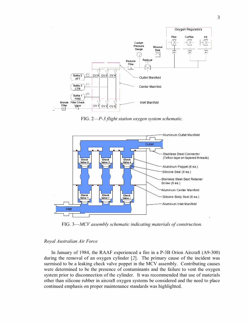
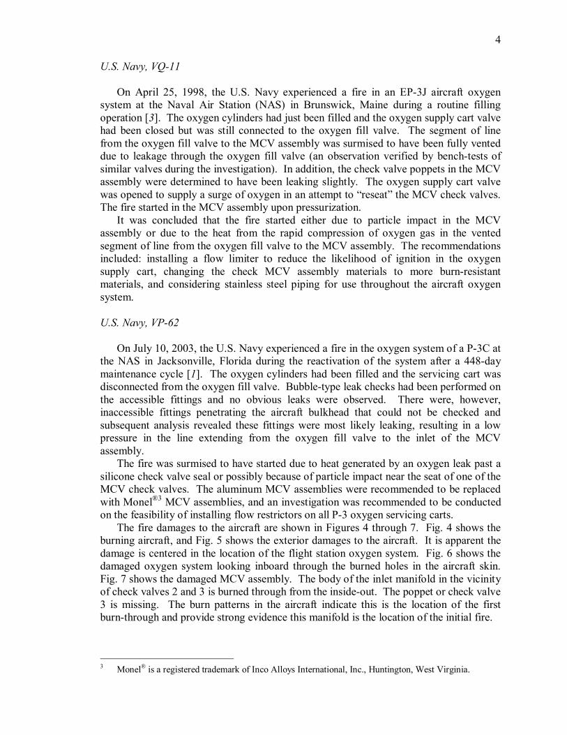
An isometric representation of a P3 flight station oxygen system and its location in the aircraft are shown in Fig. 1, and a schematic of the system is provided in Fig. 2. The construction materials for the MCV assembly are indicated in Fig. 3. The inlet and outlet fittings were stainless steel with Teflon ®2 tape on tapered threads. The inlet, center, and outlet manifold were an aluminumbased alloy. The six check valve poppets were anodized aluminumbased alloy with a silicone seat and a stainless steel seat retainer screw.
FIG. 1—Isometric view of the P3 flight station oxygen system. [1].
2 Teflon ® is a registered trademark of E. I. DuPont de Nemours & Co., Wilmington, Delaware.
3
FIG. 2—P3 flight station oxygen system schematic.
. FIG. 3—MCV assembly schematic indicating materials of construction.
Royal Australian Air Force
In January of 1984, the RAAF experienced a fire in a P3B Orion Aircraft (A9300) during the removal of an oxygen cylinder [2]. The primary cause of the incident was surmised to be a leaking check valve poppet in the MCV assembly. Contributing causes were determined to be the presence of contaminants and the failure to vent the oxygen system prior to disconnection of the cylinder. It was recommended that use of materials other than silicone rubber in aircraft oxygen systems be considered and the need to place continued emphasis on proper maintenance standards was highlighted.
4
U.S. Navy, VQ11
On April 25, 1998, the U.S. Navy experienced a fire in an EP3J aircraft oxygen system at the Naval Air Station (NAS) in Brunswick, Maine during a routine filling operation [3]. The oxygen cylinders had just been filled and the oxygen supply cart valve had been closed but was still connected to the oxygen fill valve. The segment of line from the oxygen fill valve to the MCV assembly was surmised to have been fully vented due to leakage through the oxygen fill valve (an observation verified by benchtests of similar valves during the investigation). In addition, the check valve poppets in the MCV assembly were determined to have been leaking slightly. The oxygen supply cart valve was opened to supply a surge of oxygen in an attempt to “reseat” the MCV check valves. The fire started in the MCV assembly upon pressurization.
It was concluded that the fire started either due to particle impact in the MCV assembly or due to the heat from the rapid compression of oxygen gas in the vented segment of line from the oxygen fill valve to the MCV assembly. The recommendations included: installing a flow limiter to reduce the likelihood of ignition in the oxygen supply cart, changing the check MCV assembly materials to more burnresistant materials, and considering stainless steel piping for use throughout the aircraft oxygen system.
U.S. Navy, VP62
On July 10, 2003, the U.S. Navy experienced a fire in the oxygen system of a P3C at the NAS in Jacksonville, Florida during the reactivation of the system after a 448day maintenance cycle [1]. The oxygen cylinders had been filled and the servicing cart was disconnected from the oxygen fill valve. Bubbletype leak checks had been performed on the accessible fittings and no obvious leaks were observed. There were, however, inaccessible fittings penetrating the aircraft bulkhead that could not be checked and subsequent analysis revealed these fittings were most likely leaking, resulting in a low pressure in the line extending from the oxygen fill valve to the inlet of the MCV assembly.
The fire was surmised to have started due to heat generated by an oxygen leak past a silicone check valve seal or possibly because of particle impact near the seat of one of the MCV check valves. The aluminum MCV assemblies were recommended to be replaced with Monel ®3 MCV assemblies, and an investigation was recommended to be conducted on the feasibility of installing flow restrictors on all P3 oxygen servicing carts.
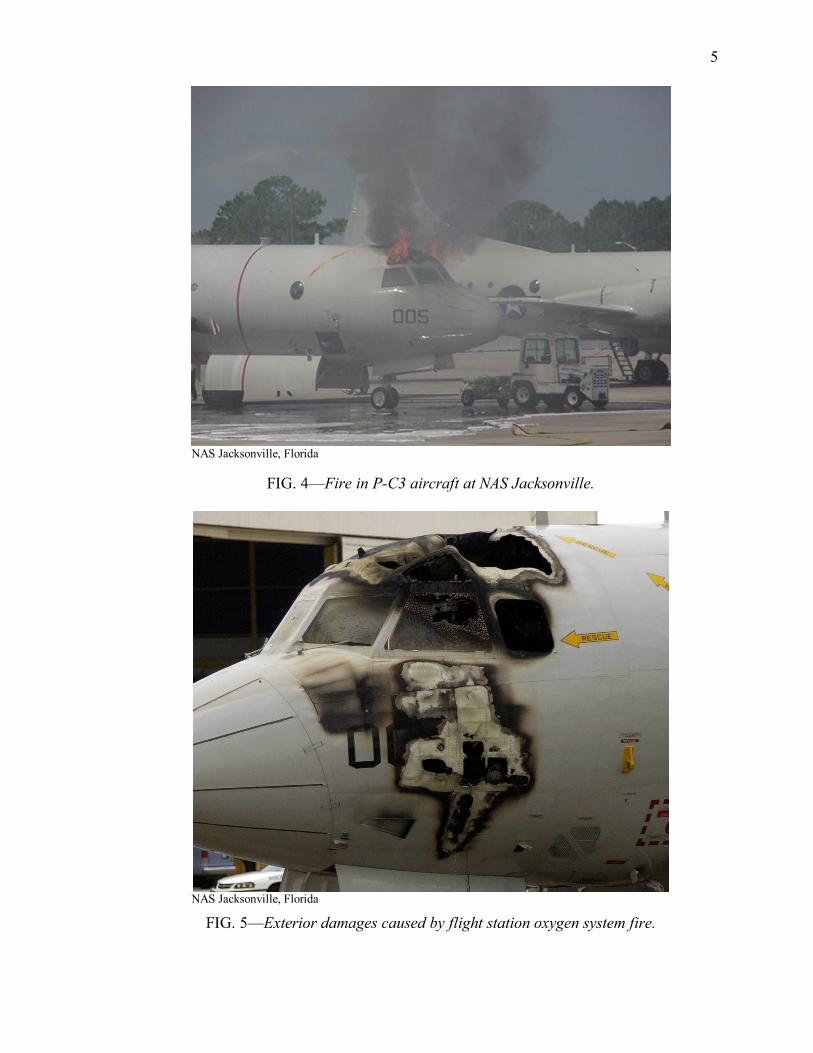
The fire damages to the aircraft are shown in Figures 4 through 7. Fig. 4 shows the burning aircraft, and Fig. 5 shows the exterior damages to the aircraft. It is apparent the damage is centered in the location of the flight station oxygen system. Fig. 6 shows the damaged oxygen system looking inboard through the burned holes in the aircraft skin. Fig. 7 shows the damaged MCV assembly. The body of the inlet manifold in the vicinity of check valves 2 and 3 is burned through from the insideout. The poppet or check valve 3 is missing. The burn patterns in the aircraft indicate this is the location of the first burnthrough and provide strong evidence this manifold is the location of the initial fire.
3 Monel ® is a registered trademark of Inco Alloys International, Inc., Huntington, West Virginia.
5
NAS Jacksonville, Florida
FIG. 4—Fire in PC3 aircraft at NAS Jacksonville.
NAS Jacksonville, Florida
FIG. 5—Exterior damages caused by flight station oxygen system fire.

6
NAS Jacksonville, Florida
FIG. 6—Damages to flight station oxygen system components looking inboard through the holes (some of the damaged aircraft skin have been removed) in the aircraft exterior
shown in Fig. 2.
NAS Jacksonville, Florida
FIG. 7—Damages to the MCV assembly.

7
Analysis of VP62 Fire
On August 6, 2005, WSTF personnel were requested by NAS Jacksonville to assist in performing a failure analysis for the VP62 P3C aircraft fire. The following analyses comprise the results of WSTF’s efforts to understand the cause of the VP62 fire. The results presented hereafter were generated by the WSTF team and are unofficial findings.
This fire incident involved the ignition and burning of the components in the flight station oxygen system. Much evidence of the events was consumed or destroyed during the course of the fire. Therefore, this analysis attempted to reconstruct possible ignition scenarios suggested by the data and findings that were available after the incident. Since this is the case with most fires that occur in oxygenenriched environments, the fire investigator has a difficult task and cannot provide definitive conclusions.
WSTF’s approach to this analysis was to consider the events leading to the fire, determine the system conditions at the start of the fire, postulate (as best as could be determined by the physical evidence) the origin of the fire, and, finally, consider the possible ignition mechanisms that may have initiated the fire.
Events Leading to Fire
The P3 aircraft was located on the flight line of the VP62 squadron after a 448day maintenance cycle had been completed. The day before the fire, the subject aircraft oxygen system had been purged with nitrogen gas and a pad pressure of approximately 125 psig (960 kPa) had been left on the system. On the day of the fire, the flexible hose from the sixbottle oxygen servicing cart was connected to the oxygen fill valve, the isolation valve on the flexible hose was opened, and the pressure regulator on the oxygen cart was increased to approximately 200 psig (1 500 kPa). A 1min hold occurred during which time the technician in the cockpit touched the oxygen cylinders to verify flow had occurred into each cylinder. This was verified by a slight increase in temperature of the cylinder wall. The pressure was increased to 400 psig in 100 psig (2 900 kPa in 790 kPa) increments with a 1min hold at each step. A “bubbletype” leak check was performed on the components accessible to the technician in the cockpit at 400 psig (2 900 kPa). The pressure was increased to 600 psig in 100 psig (4 200 kPa in 790 kPa) increments with a 1min hold at each step. At 600 psig (4 200 kPa), the system was flowed through each of the three smoke mask assemblies to flush the remaining nitrogen gas from the system. The pressurization sequence proceeded to 1 900 psig in 100 psi (13 000 kPa in 790 kPa) increments with a 1min hold at each step. “Bubbletype” leak checks were performed at 800, 1 200, and 1 900 psig (5 600, 1 200, and 3 200 kPa).
During the “bubbletype” leak check at 1 900 psig (13 000 kPa) the technician outside the aircraft closed the valve on the flexible hose, disconnected the flexible hose from the oxygen fill valve, checked the check valve for leaks by putting a hand near or on the fitting, observed there was no obvious leakage, and connected and torqued the brass cap onto the inlet of the oxygen fill valve. The “bubbletype” leak check was completed and the technician inside the aircraft was collecting gear to depart the aircraft when the fire occurred. Both technicians estimated the time from completion of the pressurization cycle to the start of the fire was between 1 and 2 min.

8
Conditions at Start of Fire
The operating conditions of the flight station oxygen system at the time of the fire were concluded to be as follows:
a) The portion of the system from the oxygen fill valve to the inlet check valves 1, 2, and 3 in the MCV assembly was between 1 900 psig (13 000 kPa) and ambient pressure. The investigation revealed it was highly probable this portion of the system leaked significantly during the delay from the final pressurization to 1 900 psig (13 000 kPa) and the time of the fire. This was evidenced by significant corrosion of the sealing surface of the connection to the pressure bulkhead feedthrough fitting. In addition, this section of line was reported by flightline personnel to be very likely to leak down.
b) The portion of the system from the top of check valves 1, 2, and 3 to the oxygen pressure reducer valve assembly was at 1 900 psig (13 000 kPa). It is also probable there was at least a small leak from the MCV assembly center manifold across the silicone seat of check valve 3 into the fill line.
c) Except for leaks, the system was quiescent. At least 1 and up to 2 min had passed since the last pressurization step from 1 800 to 1 900 psig (12 500 to 13 000 kPa) and the system was not flowing; i.e., the smoke masks were not in use.
Postulated Fire Origin
As noted previously, the damages to the aircraft were centered in the location of the flight station oxygen system [Fig. 5] and the MCV assembly was the central location from which the fire emanated. A large portion of the MCV assembly was burned away [Fig. 7] and the component appeared to have burned from the inside out. The oxygen fill valve was intact, as were the overboard discharge indicator, the pressure reducer assembly, the oxygen cylinder and valve assembly, the diluter demand oxygen regulators, and the smoke mask assemblies. The damages to the tubing in the vicinity of the MCV assembly could be easily explained as collateral damages occurring after the fire burned through the MCV assembly wall. Therefore, the MCV assembly was postulated as being the origin of the fire.
Possible Ignition Mechanisms
There are eleven ignition mechanisms that are often considered while performing oxygen system compatibility assessments [4]. These ignition mechanisms were considered as possible sources of heat that may have initiated the fire and are listed here alphabetically. The mechanisms are also rated to indicate their possibility of being the active ignition mechanism in this fire.
Compression Heating—High temperatures generated when gas is quickly pressurized from a low to a high pressure. The high temperature occurs in the compressed gas at the downstream end of the pressurization event. The characteristic elements required for ignition by compression heating are as follows: 1) a pressure ratio adequate to produce temperatures exceeding the ignition temperature of exposed materials; 2) a rapid pressurization event (i.e., less than one second); and 3) an exposed, ignitable material at the downstream end of the pressurization event.

9
In this case, the final pressurization cycle was reported to be from approximately 1 700 to 1 900 psig (12 000 to 13 000 kPa). This pressure ratio is 1.1 and produced a maximum temperature rise of 17 °F (8.3 °C). In addition, the pressurization event occurred up to 2 min prior to the fire, which was too long for the fire to have been caused by the heat of compression. Finally, in the fill mode, the inlet manifold check valves are not at the downstream end of the pressurization event. Compression heating was concluded to be almost impossible as the ignition mechanism causing this fire.
Valve Seat Chatter—A valve seat moving with lowamplitude, highfrequency oscillations can produce heat by friction.
In this case, there are no springs in the MCV assembly check valves and each valve is pressurebalanced. In addition, there is no physical evidence from check valves 1 or 2 that chatter occurred in this component. Valve seat chatter was concluded as being almost impossible as the ignition mechanism causing this fire.
Electrical Arc—An electrical charge arcing through ungrounded or shortcircuited, powered components can cause ignition of flammable materials located nearby.
In this case the component was not electrically powered. Therefore, ignition by electrical arc was considered to be almost impossible.
Flow Friction—Oxygen leaking across a polymer in such a way that heat is generated within the polymer. This ignition mechanism has not been duplicated in a controlled test environment; however, it has been surmised as a possibility once all other possible ignition mechanisms have been eliminated. The characteristic elements required for ignition by flow friction are as follows: 1) a pressure drop greater than 500 psi (3 400 kPa) (fires have not been observed by this mechanism at pressures lower than this), 2) a small leak or “weeping” flow at an external seal or across an internal valve seat, and 3) an exposed nonmetal in the flow path of the leak. A chafed or abraded surface seems to increase the heating effect. In addition, the heat generated by this ignition mechanism can be enhanced by the presence of a small, vibrating “ribbon” of the polymer seat material. This “ribbon” can be oscillated like a reed in a musical instrument at high frequencies. If the oscillating material is constrained it can generate heat by mechanical friction, thus contributing to the overall temperature rise in the material.
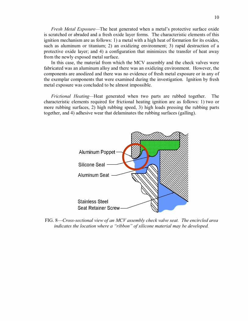
In this case, the pressure drop from the center manifold to the inlet manifold was as high as 1 900 psi (13 000 kPa) due to leakage in the inlet line. A small leak from the center manifold to the inlet manifold across the silicone seat of check valve 3 was probable. Flight line technicians reported such leaks are common and often measures are taken to stop such leaks. This was explicitly the case in the U.S. Navy VQ11 fire incident previously mentioned. It was surmised that a similar leak existed in this check valve as well. The silicone seat material in the MCV assembly check valves has a relatively low ignition temperature, 504 °F (262 °C). Additionally, a “ribbon” of silicone material exists at the outer diameter of the molded silicone seal that could produce heat if vibrated by the flow and constrained by the poppet and seat. Fig. 8 provides an illustration of an open MCV assembly check valve and indicates where a “ribbon” of silicone material may be developed. Therefore, ignition by flow friction was concluded to be highly probable.
10
Fresh Metal Exposure—The heat generated when a metal’s protective surface oxide is scratched or abraded and a fresh oxide layer forms. The characteristic elements of this ignition mechanism are as follows: 1) a metal with a high heat of formation for its oxides, such as aluminum or titanium; 2) an oxidizing environment; 3) rapid destruction of a protective oxide layer; and 4) a configuration that minimizes the transfer of heat away from the newly exposed metal surface.
In this case, the material from which the MCV assembly and the check valves were fabricated was an aluminum alloy and there was an oxidizing environment. However, the components are anodized and there was no evidence of fresh metal exposure or in any of the exemplar components that were examined during the investigation. Ignition by fresh metal exposure was concluded to be almost impossible.
Frictional Heating—Heat generated when two parts are rubbed together. The characteristic elements required for frictional heating ignition are as follows: 1) two or more rubbing surfaces, 2) high rubbing speed, 3) high loads pressing the rubbing parts together, and 4) adhesive wear that delaminates the rubbing surfaces (galling).
FIG. 8—Crosssectional view of an MCV assembly check valve seat. The encircled area indicates the location where a “ribbon” of silicone material may be developed.

11
In this case, friction was present due to the check valve poppet moving inside the MCV assembly inlet manifold. However, there were no forces pressing the poppet against the manifold. In addition, there was no evidence of galling in any of the exemplar components that were examined during the investigation. Ignition by frictional heating was concluded to be almost impossible.
Mechanical Impact—Single or repeated impacts on a material with sufficient force to ignite it. The characteristic elements required for ignition by mechanical impact are as follows: 1) large impact or repeated impact loading and 2) a nonmetal material at the point of impact. Except for very reactive metal alloys, such as titanium, magnesium, and lithiumbase alloys or various leadcontaining solders, this ignition mechanism is effective in igniting only nonmetallic materials and contaminants [5].
In this case, mechanical impact does not occur, instead there was a lowimpact seating of the MCV assembly check valves 1, 2, and 3 as the differential pressure dropped and flow from the bottles toward the inlet occurred. Ignition by mechanical impact was concluded to be almost impossible.
Particle Impact—Heat generated when small particles strike a material with sufficient velocity to ignite the particle and/or the material being struck. The characteristic elements required for ignition by particle impact are as follows: 1) particles that can be entrained in the flowing oxygen, 2) oxygen flowing at a high velocity that will impart high kinetic energy to the entrained particles (WSTF test results indicate that iron particles will ignite stainless steel targets at velocities as low as 150 ft/s (46 m/s) [6]), 3) an impact point at which the particle(s) will reside momentarily, and 4) a flammable particle and/or target.
In this case, all the characteristic elements could have existed in this component. That particles existed in the component was indicated by examination of exemplar units, which contained particulate contamination. The pressure drop across a possibly leaking seat from the center manifold to the inlet manifold would generate a high gas velocity. A highvelocity particle could have impacted the stainless steel seat retainer screw as shown in Fig. 9. The stainless steel screw is flammable at 1 900 psig (13 000 kPa) and the particle was assumed to have been flammable. Ignition by particle impact was concluded to be possible.
PCTFE/Aluminum Reaction—A heatproducing chemical reaction can occur when aluminum is sheared in the presence of polychlorotrifluoroethylene (PCTFE) grease. The characteristic elements for this ignition mechanism are as follows: 1) the presence of chlorinecontaining lubricant, such as PCTFE grease; 2) aluminum metal alloy; and 3) shear fracture of the aluminum part.
In this case, chlorinecontaining greases were not used. Therefore, ignition by this reaction was considered almost impossible.

12
FIG. 9—Crosssectional view of the MCV assembly check valve poppet. The arrow indicates a possible particle impact location.
Resonance—acoustic oscillations within a cavity that causes rapid temperature rise. The characteristic elements required for ignition by resonance are as follows: 1) a “tuned” resonance cavity and 2) acoustic resonance that is often audible. Particulate or contaminant debris in the cavity can ignite making this ignition mechanism more severe [7].
In this case, the configuration to produce a “tuned” resonance cavity did not exist. Therefore, ignition by resonance was considered almost impossible.
Static Discharge—Accumulated static charge that discharges with enough energy to ignite surrounding materials. The characteristic elements required for static discharge to cause an ignition are as follows: 1) flow of gas or rubbing of flexible parts causing an accumulation of static charge on a nonconductive surface and 2) arcing of the accumulated electrical charge between materials having different electrical potentials. It has been observed that two charged surfaces are not likely to arc unless one material is conductive. Finally, the buildup of static charge is more severe in a dry environment.
In this case, the flight station oxygen system components were electrically connected to one another and the system was grounded to the aircraft, draining any builtup charges. Therefore, ignition by static discharge was considered almost impossible.
Kindling Chain
It is apparent that a kindling chain reaction did occur in the flight station oxygen system since the inlet manifold of the MCV assembly was burned out. The physical evidence is consistent with a fire starting in the seat of check valve 3 (probably by flow friction, or in check valve 2 or 3, possibly by particle impact). This fire propagated to the aluminum poppet or the stainless steel retainer screw to the aluminum MCV assembly body. The fire burned through the MCV assembly body, releasing pressurized oxygen and the accompanying burning debris to the cabin. Several torches of flame and debris developed as the oxygen flowed out of the cylinders through the burned breeches in the system.

13
Because of this dramatic kindling chain and the two fires of similar origin and magnitude that had occurred previously in the RAAF and U.S. Navy, the MCV assembly was recommended to be replaced with one made from a burnresistant material, such as Monel 400 or Monel K500. Such a replacement would harden this system against ignition and burn propagation and dramatically reduce the likelihood of a catastrophic fire occurring. This recommendation, which was also made after the analyses of the previous fires, has been implemented. The entire U.S. and Canadian fleets of P3 aircraft have been retrofitted with Monelbodied MCV assemblies with an upgraded design and more burnresistant materials.
MCV Assembly Check Valve Seal Fires
During the performance of the failure analysis on the VP62 flight station oxygen system fire, WSTF personnel received twelve check valve poppets from NAS Jacksonville personnel. Eleven of the twelve poppets were damaged. Fig. 10 shows a typical damaged poppet and an undamaged poppet.
The specific history of the damaged poppets was unknown, but what was known is: 1) the poppets were removed from various P3 flight station oxygen systems serviced at NAS Jacksonville; 2) they were removed and replaced because of their appearance or because they did not pass the leak check; 3) they were in use in P3 flight station oxygen systems that had been serviced using the standard fill procedures; and 4) it is likely that the section of the oxygen system from the oxygen fill valve to the inlet side of check valves 1, 2, and 3 leaked down to nearambient pressure soon after the fill procedure was completed.
Description of Burned Seals
A crosssectional view of one of the eleven damaged poppets is shown in Fig. 11. It can be seen that the green silicone seal is damaged. Further observation revealed the silicone seal had been, in fact, partially burned. However, the fire damage did not propagate to consume the entire silicone seal nor did it propagate to the aluminum alloy check valve poppet or the stainless steel seat retaining screw.
The obvious question was raised regarding the cause of the burn damage to the eleven poppets. A second question was raised regarding why the fires in the eleven burn damaged poppets did not propagate to the metal portions of the MCV assembly. The WSTF oxygen team analyzed the components provided by NAS Jacksonville in an attempt to answer those questions. What follows are the results of that analysis [8]. These results represent the WSTF team’s opinion and are not official findings.

14
wstf0803e2752
FIG. 10—A typical damaged MCV assembly check valve poppet (left) and an unused, undamaged poppet (right) as shown with a scale in inches.
wstf0803e3004
FIG. 11—Crosssectional view of a burndamaged MCV assembly check valve poppet.

15
Assumptions Related to Conditions Leading to Seal Fires
The eleven damaged check valves were assumed to have been removed from MCV assemblies that had been in service. It was further assumed that during the service they were subjected to certain conditions. First, the pressure had ranged from 1 500 to 1 900 psig (10 000 to 13 000 kPa) (the normal operating range of the flight station oxygen system bottles). Second, the check valve poppets and seals had been pressed against the check valve seats with a pressure drop of up to 1 900 psig (13 000 kPa) across the seal, because the inlet line leaked. Third, during the normal refilling procedure, the flexible hose from the oxygen servicing cart had been installed to the oxygen fill valve, the isolation valve had been opened, and the regulator had been increased to 200 psig (1 500 kPa), causing a pressure surge from ambient pressure to 200 psig (1 500 kPa) at the upstream side of the seated check valve poppets. And fourth, leaks from the center manifold to the inlet manifold had been occasionally occurring across the check valve seals.
Possible Ignition Mechanisms
All the aforementioned ignition mechanisms were evaluated to determine the cause of the burndamage, which occurred to the eleven check valve seals. Of those ignition mechanisms, three were concluded to have been possible:
Compression heating—At the start of the refilling operation, when the system downstream of check valves 1, 2, and 3 was pressurized to at least 1 500 psig (10 000 kPa) and the inlet line was at ambient pressure (due to presumed leakage), all the characteristic elements of this ignition mechanism were present.
1) Pressure ratio: When the oxygen servicing cart flex hose was attached to the oxygen fill valve and the flex hose isolation valve was opened, the length of line from the oxygen cart regulator to the upstream side of the MCV assembly check valves was at ambient pressure. When the servicing cart regulator was increased to 200 psig (1 500 kPa) to accomplish the first incremental step of the pressurization sequence, the gas in the line was rapidly compressed to 200 psig (1 500 kPa). This is a pressure ratio of 14.6:1 and it produces a maximum temperature of 680 °F (360 °C). Silicone can be ignited at temperatures as low as 503 °F (262 °C) [9].
2) Rapid pressurization event: This occurred when the oxygen cart regulator was increased from ambient to 200 psig (1 500 kPa).
3) Exposed nonmetal material at the downstream end: The silicone forms the seal at the dead end of this pressurized circuit. What was unknown is the degree of protection provided to the silicone seal by the surrounding metal when the check valve poppet was seated.
Compression heating was considered to be a probable ignition mechanism for the damages observed in the eleven MCV assembly check valve seals.
Flow Friction—All the characteristic elements of ignition by flow friction are present in the MCV assemblies.
1) Pressure greater than 500 psig (3 500 kPa): In this case, the pressure differential across the check valve seat is up to 1 900 psi (13 000 kPa).

16
2) Leak of “weeping” flow across external or internal seals: Fig. 8 illustrates the check valve seals are configured so a delaminated ribbon of silicone can easily be formed and oxygen could flow between this delaminated ribbon and the poppet body.
3) Exposed nonmetal in the flow path: The silicone seal material is exposed to the leaking oxygen.
As was previously mentioned, recent experiments at WSTF indicate pressurized gas flowing past a ribbon of elastomeric material can cause a vibration of the material. If, in another location near the leak, the vibrating material is partially constrained from moving it will be heated at the point that the constraining part touches the elastomer. In preliminary experiments using 30 psig (310 kPa) air flowing past a ribbon of silicone material, heat damage to the silicone material was observed. This scenario is present in the MCV assembly check valve seal. Fig. 12 shows a closeup view of a delaminated fiber of silicone seal material that may have been damaged by heat from this postulated ignition mechanism.
Flow friction heating was considered a highly probable cause of the fire damages observed in the eleven MCV assembly seals.
Particle Impact—All the characteristic elements required for ignition by particle impact could exist in these components.
1) Particles in the flowing oxygen: These check valves were contaminated. See the contamination in Fig. 10 and Fig. 12.
2) High gas velocity: If a leak was occurring across the silicone seal into a low pressure inlet manifold, sonic velocity could occur.
3) Impact point and residence time: Particles could impact on the side of the stainless steel seat retainer screw and reside there momentarily (Fig. 9).
4) Flammable particle and target: The stainless steel screw is flammable. Particle impact was considered a possible ignition mechanism causing the damages
observed in the eleven MCV assembly seals.
Kindling Chain
Of the eleven damaged check valve poppet assemblies provided to WSTF, none of the aluminum bodies were catastrophically damaged. It is apparent that the silicone seals burned, but the burning did not propagate to the aluminum bodies. However in the three catastrophic aircraft fires that have occurred in P3 flight station oxygen systems, it is apparent that a kindling chain reaction did occur. The question is raised: Why didn’t the fires propagate in the eleven poppets addressed in this paper?

17
wstf0803e3002
FIG. 12—Closeup view of delaminate fiber of silicone seal material showing possible heat damage due to postulated flow friction heating.
The anodized layer on the aluminum poppet body was surmised to have protected it from burning. The literature data indicate aluminum oxide is a coherent protective oxide that must be breached before ignition of the metallic aluminum substrate material can occur [10]. An anodized layer has been found to provide additional protection against the ignition of aluminum even beyond that provided by the naturally occurring oxide [11]. In addition, tests have been performed at WSTF in which highdensity polyethylene ignition promoters were pressed over the ends of aluminum rods and ignited in oxygen at up to 10 000 psi (69 000 kPa). The rods were suspended vertically from the top and the polyethylene promoters were located at the bottom end of the rods. In most cases, see Fig. 13 for an example of five rods, the aluminum rod melted and deformed but did not ignite.
Analysis confirmed the aluminum oxide film, even though it was obviously thermally softened and deformed, provided an ignitioninhibiting barrier between the aluminum and the oxygen. This protective oxide film of both naturally occurring and chemically applied oxides is thought to be what prohibited the propagation of the fire in the eleven MCV assembly check valve poppets.

18
wstf07902434
FIG. 13—Aluminum rods that did not ignite when exposed to burning polyethylene at various oxygen pressures.
Conclusion
The results of WSTF’s check valve poppet analysis and the data collected from the three P3 aircraft oxygen system fires illustrate the need for a careful selection of materials to prevent fires in oxygenenriched environments. The ignition mechanisms attributed to the seal fires were concluded to be from compression heating, particle impact, or flow friction. The fires led to the realization that the MCV assembly required a burnresistant material, which resulted in the U.S. and Canadian fleets of P3 aircraft replacing the assemblies with an upgraded design. WSTF performed further studies to investigate eleven other MCV poppets in which the silicone seal ignited and burned but the fire did not propagate to the aluminum check valve body. It was determined that the anodized layer on the aluminum poppet protected the valve from burning. This ignition inhibiting barrier prevented the heated and softened metal from catastrophic fire.
References
[1] Hanson, J. “P3 HMR Final Report,” COMNAVAIRSYSCOM, Patuxant River, Maryland, August 3, 2003.
[2] Grubb, J.W. “Case Study of Royal Australian Air Force P3B Orion aircraft Ground Oxygen Fire Incident,” Flammability and Sensitivity of Materials in Oxygen Enriched Atmospheres: Second Volume, ASTM STP 910, M.A. Benning, Ed., American Society for Testing and Materials, Philadelphia, 1986, pp. 171179.

19
[3] Hollingsworth, J. “Preliminary Report to the Accident Board on the Engineering Investigation of the Oxygen System Components from the Fire on EP3J BUNO 152745 at NAS Brunswick 25 April 1998,” Navy Oxygen Systems Fleet Support Team, Naval Air Warfare Center Aircraft Division, Patuxent River, Maryland, June 7, 1998.
[4] Rosales, K., Shoffstall M., and Stoltzfus J., “Oxygen Compatibility Assessment on Components and Systems,” Eleventh International Symposium on Flammability and Sensitivity of Materials in OxygenEnriched Atmospheres, ASTM G04 Compatibility and Sensitivity of Materials in Oxygen Enriched Atmospheres Committee, Washington DC, October 1617, 2006.
[5] Bryan, C.J., “NASA Mechanical Impact Testing in HighPressure Oxygen,” Flammability and Sensitivity of Materials in OxygenEnriched Atmospheres, ASTM STP 812, B.L. Werley, Ed., American Society for Testing and Materials, Philadelphia, 1983, pp.942.
[6] Williams, R.E., Benz, F.J., and McIlroy, K., “Ignition of Steel Alloys by Impact of LowVelocity Iron/Inert Particles in Gaseous Oxygen,” Flammability and Sensitivity of Materials in OxygenEnriched Atmospheres, ASTM STP 986, D.W. Schroll, Ed., American Society for Testing and Materials, Philadelphia, 1988, pp. 7284.
[7] Phillips, B.R. “A Thesis Entitled Resonance Tube Ignition of Metals,” The University of Toledo, Ohio, 1975
[8] Peralta, S., Shoffstall, M., Slockers, M., and Stoltzfus, J., “Oxygen Failure Analysis Report, P3 High Pressure Oxygen Manifold and Check Valve Assembly Seal Fires, OXHAZ/FAIL 0260,” National Aeronautics and Space Administration, White Sands Test Facility, Las Cruces, NM, August 2001.
[9] Beeson, H., Smith, S., and Stewart, W., “Safe Use of Oxygen and Oxygen Systems: Guidelines for Oxygen System Design, Materials Selection, Operations, Storage, and Transportation,” ASTM Manual 36, Beeson, H.D., Stewart, W.F., and Woods, S.S., Eds., American Society for Testing and Materials, Philadelphia, 2000.
[10] Lowrie, R. “Oxygen Compatibility of Metals and Alloys,” Flammability and Sensitivity of Materials in OxygenEnriched Atmospheres: Volume 6, ASTM STP 1197, D. Janoff and Stoltzfus, J. Eds., American Society for Testing and Materials, Philadelphia, 1993.
[11] Forsyth, E., and Stoltzfus, J. “Ignition Resistance of Hard (Type III) Anodized Aluminum to Particle Impact,” Flammability and Sensitivity of Materials in OxygenEnriched Atmospheres: Volume 8, ASTM STP 1319, W.T. Royals, T.C. Chou, and T.A. Steinberg Eds., American Society for Testing and Materials, Philadelphia, 1997.