fisher 8532 high-performance butterfly valve · instruction manual d101550x012 8532 valve june 2018...
TRANSCRIPT

www.Fisher.com
Fisher™ 8532 High-Performance Butterfly Valve
ContentsIntroduction 1. . . . . . . . . . . . . . . . . . . . . . . . . . . . . . . . .
Scope of Manual 1. . . . . . . . . . . . . . . . . . . . . . . . . . . . .Description 1. . . . . . . . . . . . . . . . . . . . . . . . . . . . . . . . .Specifications 2. . . . . . . . . . . . . . . . . . . . . . . . . . . . . . .Educational Services 2. . . . . . . . . . . . . . . . . . . . . . . . .
Installation 4. . . . . . . . . . . . . . . . . . . . . . . . . . . . . . . . . .Valve Orientation 5. . . . . . . . . . . . . . . . . . . . . . . . . . . .Before Installing the Valve 5. . . . . . . . . . . . . . . . . . . . .Adjusting the Actuator Travel Stops or Travel 8. . . . .Installing the Valve 8. . . . . . . . . . . . . . . . . . . . . . . . . . .
Packing Adjustment and Shaft Bonding 11. . . . .Maintenance 12. . . . . . . . . . . . . . . . . . . . . . . . . . . . . . . .
Removing and Replacing the Actuator 13. . . . . . . . .Packing Maintenance 13. . . . . . . . . . . . . . . . . . . . . . . .Removing the Valve 15. . . . . . . . . . . . . . . . . . . . . . . . .Seal Maintenance 16. . . . . . . . . . . . . . . . . . . . . . . . . . .
PTFE Seals 17. . . . . . . . . . . . . . . . . . . . . . . . . . . . .NOVEX, Phoenix III and/or
Phoenix III Fire‐Tested Seals 18. . . . . . . . . . . .Anti‐Blowout Design, Packing, Valve Shaft,
Disk, and Bearing Maintenance 19. . . . . . . . . . . . .Installing the Two‐Piece Shaft 21. . . . . . . . . . . . .
Gasket Retainer 22. . . . . . . . . . . . . . . . . . . . . . . . . . . .Parts Ordering 23. . . . . . . . . . . . . . . . . . . . . . . . . . . . . . .Parts List 25. . . . . . . . . . . . . . . . . . . . . . . . . . . . . . . . . . .
Figure 1. Fisher 8532 Valve with 1061 Actuator andFIELDVUE™ DVC6200 Digital Valve Controller
W9138-2
Introduction
Scope of ManualThis instruction manual provides installation, maintenance, and parts information for NPS 14 through 48 Fisher 8532high-performance butterfly valves.
Do not install, operate, or maintain an 8532 valve without being fully trained and qualified in valve,actuator, and accessory installation, operation, and maintenance. To avoid personal injury or propertydamage, it is important to carefully read, understand, and follow all the contents of this manual,including all safety cautions and warnings. If you have any questions about these instructions, contactyour Emerson sales office before proceeding.
DescriptionThe valve is available in either a wafer (flangeless), lugged (single‐flange), or double flange body design, with a varietyof seals and internal components. The pressure‐assisted seal provides tight shutoff. The spline or keyed drive shaftcombines with a variety of actuators. Maximum inlet pressure/temperature ratings are consistent with CL150 andCL300.
Instruction ManualD101550X012
8532 ValveApril 2020

Instruction ManualD101550X012
8532 ValveApril 2020
2
Table 1. Specifications
Valve Size and End Connection Styles
� NPS 14, � 16, � 18, � 20, � 24, � 30, � 36,� 42, or � 48 valves in � wafer (flangeless),� lugged (single‐flange), or � double‐flange valvebodies with raised‐face flanges, CL150 or CL300
Maximum Pressure Drop(1)
Consistent with CL150 and CL300pressure/temperature ratings per ASME B16.34NPS 30-48: CL150/150 construction has CL150 ratedpressure retaining parts and 150 psid rated trim
Shutoff Classification Per ANSI/FCI 70‐2 and IEC60534‐4
Standard Soft Seal: Bidirectional shutoff Class VI(bubble‐tight)
NOVEX Seal: Unidirectional shutoff Class IV (preferredflow direction only(3)), Class VI optional (excludingNPS 42 and 48)
Phoenix III Seal: Bidirectional shutoff Class VI(bubble‐tight)
Phoenix III Seal for Fire‐Tested Applications:Unidirectional shutoff Class VI (reverse flow directiononly) (bubble‐tight). Fire Tested per API 607 Rev. 4.For more information contact your Emerson salesoffice.
Cryogenic: For cryogenic seal applications, consultyour Emerson sales office.
Available Seal Configurations
Standard ConstructionsSee figure 2 and table 2
Standard Construction Materials
See table 2
Flow Characteristic
Modified equal percentage
Flow Coefficients
See Fisher Catalog 12
Flow Coefficient Ratio(2)
100 to 1
Noise Levels
See Fisher Catalog 12 for sound/pressure levelprediction
Valve Body Classification
Wafer and Lugged face‐to‐face dimensions are incompliance with MSS SP68 and API 609 standardsthrough NPS 24. Double Flange valve bodies complywith API 609 short face-to-face dimensions. Valvebodies are designed for installation between ASMEB16.5 CL150 and CL300 raised‐face flanges
Disk Rotation
Clockwise to close (when viewing from the drive shaftend) through 90 degrees rotation
Shaft Diameter and Approximate Weight
See tables 4 and 5
ENVIRO‐SEAL™ Packing
This optional packing system provides improvedsealing, guiding, and transmission of loading force tocontrol liquid and gas emissions. Contact yourEmerson sales office for availability of ENVIRO‐SEALpacking
1. The pressure/temperature limits in this manual, and any applicable code or standard limitation should not be exceeded.2. Ratio of maximum flow coefficient to minimum usable flow coefficient may also be called rangeability.3. For optimum seal performance, the preferred valve orientation at shutoff is with the retaining ring downstream from the high pressure side of the valve.
Educational ServicesFor information on available courses for Fisher 8532 valves, as well as a variety of other products, contact:
Emerson Automation SolutionsEducational Services - RegistrationPhone: 1-641-754-3771 or 1-800-338-8158E-mail: [email protected]/fishervalvetraining

Instruction ManualD101550X012
8532 ValveApril 2020
3
Table 2. Material Temperature Ratings
COMPONENT AND MATERIAL OF CONSTRUCTION(1)TEMPERATURE RANGE
�C �F
Valve Body(2)
Carbon Steel (WCC or SA 516-70)(7)
CF8M (316 SST)
CF8M/CF10M (316/316H)(3) Dual-Certified
-29 to 427
-198 to 538
over 538 to 816
-20 to 800
-325 to 1000
over 1000 to 1500
Disk
CF8M (316 SST)
CF8M/CF10M (316/316H)(3) Dual-Certified
-198 to 538
over 538 to 816
-325 to 1000
over 1000 to 1500
Disk Coating
Chromium Carbide
Chrome Plating
Chromium Coating
-198 to 916
-254 to 427
-254 to 593
-325 to 1500
-425 to 800
-425 to 1100
Shaft
S20910
S17400 (17-4 pH 1025)
N07718
N07750
N05500
-198 to 538
-73 to 427
-254 to 704
over 593 to 816
-198 to 482
-325 to 1000
-100 to 800
-425 to 1300
over 1100 to 1500
-325 to 900
Bearings(6)
PEEK (standard)
S31600(4)
R30006 (Alloy 6)
Bronze
-73 to 260
-198 to 816
-198 to 816
-254 to 302
-100 to 500
-325 to 1500
-325 to 1500
-425 to 575
Packing
PTFE Packing and PTFE ENVIRO-SEAL Packing
Graphite packing
Graphite packing with oxidizing media
Graphite ENVIRO-SEAL Packing
-148 to 232
-198 to 916
-198 to 538
-148 to 315
-325 to 450
-325 to 1500
-325 to 1000
-325 to 600
Seal Ring and
Backup Ring
PTFE Seal Ring
Nitrile Backup O-Ring
Chloroprene Backup O-Ring
EPR Backup O-Ring
Fluorocarbon Backup O-Ring
PTFE Backup O-Ring
-29 to 93
-43 to 149
-54 to 182
-29 to 204
-73 to 204
-20 to 200
-45 to 300
-65 to 360
-20 to 400
-100 to 400
UHMWPE(5) Seal Ring (CL150 Only)
EPR Backup O-Ring
Fluorocarbon Backup O-Ring
-54 to 93
-29 to 93
-65 to 200
-20 to 200
Phoenix III and/or Fire Tested Construction
S31600 and PTFE Seal Ring with Nitrile Backup O-Ring
Chloroprene Backup O-Ring
EPR Backup O-Ring
Fluorocarbon Backup O-Ring
-40 to 149
-54 to 149
-62 to 204
-40 to 232
-40 to 300
-65 to 300
-80 to 400
-100 to 200
Seal Ring
NOVEX S31600 Seal(4) Ring (CL150)
NOVEX S31600 Seal(4) Ring (CL300)
NOVEX S21800 Seal(4) Ring (CL300)
-29 to 538
-29 to 816
-29 to 816
-20 to 1000
-20 to 1500
-40 to 1500
Cryogenic Seal Ring Contact your Emerson Sales office
GasketsFlexible Graphite
Aramid with Neoprene
-254 to 816
-254 to 538
-425 to 1500
-425 to 1000
1. NACE trim constructions are available; consult your Emerson sales office.2. Special gasket retainer bolts are required for over 482�C (900�F)3. Special retaining ring screws for lugged valves over 538�C (1000�F)4. For a complete material description, contact your Emerson sales office.5. UHMWPE stands for ultra high molecular weight polyethylene.6. Special thrust bearings are required for high temp. applications over 343�C (650�F) (with 6- and 12-inch shaft extensions). Constructions with carbon steel valves and SST disks may requirespecial thrust bearings at temperatures less than 343�C (650�F).7. Cast or wrought /plate grades used interchangeably, depending upon availability - unless requested by customer.

Instruction ManualD101550X012
8532 ValveApril 2020
4
InstallationThe valve is normally shipped as part of a control valve assembly, with the power actuator mounted on the valve. If thevalve or actuator has been purchased separately, or if the actuator has been removed for maintenance, mount theactuator on the valve, and adjust actuator travel before installing the valve into the line. This is necessary due to themeasurements that must be made during the actuator calibration adjustment process. Refer to the ActuatorMounting section of this manual and to the separate actuator instruction manual for mounting and adjustinginstructions before proceeding.
WARNING
To avoid personal injury or property damage resulting from the sudden release of pressure:
� Do not remove the actuator from the valve while the valve is still pressurized.
� Always wear protective gloves, clothing, and eyewear when performing any maintenance operation.
� Do not install the valve assembly where service conditions could exceed the limits given in this manual or on thenameplates.
� Use pressure‐relieving devices as required by government or accepted industry codes and good engineering practicesto protect from over‐pressurizing the system.
� Check with your process or safety engineer for any other hazards that may be present from exposure to process media.
� If installing into an existing application, also refer to the WARNING at the beginning of the Maintenance section in thisinstruction manual.
CAUTION
When ordered, the valve configuration and construction materials were selected to meet particular pressure, temperature,pressure drop, and controlled fluid conditions. Responsibility for the safety of process media and compatibility of valvematerials with process media rests solely with the purchaser and end‐user. Since some body/trim material combinationsare limited in their pressure drop and temperature ranges, do not apply any other conditions to the valve without firstcontacting your Emerson sales office.
1. Isolate the control valve from the line pressure, release pressure from both sides of the valve body, and drain theprocess media from both sides of the valve. If using a power actuator, shut off all pressure lines to the poweractuator, release pressure from the actuator, and disconnect the pressure lines from the actuator. Use lock‐outprocedures to be sure that the above measures stay in effect while you are working on the equipment.
See the WARNING at the beginning of the Maintenance section for more information before removing the valve fromthe pipeline.
2. Install a three‐valve bypass around the control valve assembly if continuous operation is necessary duringinspection and maintenance of the valve.
3. Inspect the valve to be certain that it is free of foreign material.
4. Be certain that adjacent pipelines are free of any foreign material, such as pipe scale or welding slag, that coulddamage the valve sealing surfaces.
CAUTION
Damage to the disk will occur if any pipe flanges or piping connected to the valve interfere with the disk rotation path.Minimum inside diameters for flanges or pipe mating with valves are shown in tables 4 and 5.

Instruction ManualD101550X012
8532 ValveApril 2020
5
Valve Orientation
The valve can be installed in any orientation, however it is recommended that the valve drive shaft be horizontal andthe actuator vertical as shown in figure 4.
Install the valve with the high‐pressure shutoff side in the direction noted by the flow arrow for proper installation, andsee figure 4 for more information.
Before Installing the Valve
WARNING
The edges of a rotating valve disk (key 2, figure 10 or 11) close with a shearing, cutting motion. To avoid personal injury,keep hands, tools, and other objects away from the disk while stroking the valve.
If the 8532 valve is equipped with a fail‐open actuator, cycle the valve into the fully closed position. Ensure the valve cannotopen during installation by using travel stops, a manual actuator, a constant supply pressure to the pneumatic actuator, orother steps as necessary.
Table 3. Valve Body Data, CL150
VALVE SIZE,NPS
SHAFT DIA. ATYOKE BEARING
FACE‐TO‐FACE DIMENSION(1)
MINIMUMI.D.(2) APPROXIMATE WEIGHT, KILOGRAMSWafer and
LuggedDouble-Flange
mm Wafer Lugged Double-Flange
14 30.2 92.1 191 331.2 71.7 94.8 152
16 31.75 101.6 216 375.2 93.9 137.9 201
18 38.1 114.3 222 418.8 139.3 178.3 243
20 44.45 127.0 229 464.1 166.9 223.6 277
24 57.15 154.0 267 580.9 255.4 350.6 434
30 76.2 158.8 --- 717 528 736 ---
36 95.3 177.8 --- 865.9 806 1120 ---
42 101.6 228.6 --- 1007.4 1302 1550 ---
48 114.3 260.4 --- 1147.3 1904 2248 ---
VALVE SIZE,NPS
SHAFT DIA. ATYOKE BEARING
FACE‐TO‐FACE DIMENSION(1)
MINIMUMI.D.(2) APPROXIMATE WEIGHT, POUNDSWafer and
LuggedDouble-Flange
Inches Wafer Lugged Double-Flange
14 1‐3/16 3.625 7.50 13.04 158 209 335
16 1‐1/4 4 8.50 14.77 207 304 443
18 1/2 4.5 8.75 16.49 307 393 535
20 1‐3/4 5 9.00 18.27 368 493 611
24 2‐1/4 6.0625 10.50 22.87 563 773 956
30 3 6.25 --- 28.23 1164 1623 ---
36 3.75 7 --- 34.09 1778 2470 ---
42 4 9 --- 39.66 2871 3418 ---
48 4.5 10.25 --- 45.17 4198 4955 ---
1. Face‐to‐face dimensions are in compliance with MSS SP68 and API 609 specifications.2. Minimum I.D. is the minimum pipe or flange I.D. required for disk swing clearance. Applies to wafer and lugged valve bodies only.

Instruction ManualD101550X012
8532 ValveApril 2020
6
Table 4. Valve Body Data, CL150/150
VALVE SIZE,NPS
SHAFT DIA. ATYOKE BEARING
FACE‐TO‐FACE DIMENSION(1)
MINIMUMI.D.(2) APPROXIMATE WEIGHT, KILOGRAMSWafer and
LuggedDouble-Flange
mm Wafer Lugged Double-Flange
30 63.5 120.7 --- 723.9 365 525 ---
36 69.9 149.4 --- 871.5 626 897 ---
42 82.6 209.6 --- 1011.9 1100 1328 ---
48 95.3 228.6 --- 1158.0 1604 1907 ---
VALVE SIZE,NPS
SHAFT DIA. ATYOKE BEARING
FACE‐TO‐FACE DIMENSION(1)
MINIMUMI.D.(2) APPROXIMATE WEIGHT, POUNDSWafer and
LuggedDouble-Flange
Inches Wafer Lugged Double-Flange
30 2.50 4.75 --- 28.50 805 1157 ---
36 2.75 5.88 --- 34.31 1380 1978 ---
42 3.25 8.25 --- 39.84 2425 2928 ---
48 3.75 9 --- 45.59 3537 4204 ---
1. Minimum ID is the minimum pipe or flange ID required for disk swing clearance. Applies to wafer and lugged valve bodies only.
Table 5. Valve Body Data, CL300
VALVE SIZE,NPS
SHAFT DIA. ATYOKE BEARING
FACE‐TO‐FACE DIMENSION(1)
MINIMUMI.D.(2) APPROXIMATE WEIGHT, KILOGRAMSWafer and
LuggedDouble-Flange
mm Wafer Lugged Double-Flange
14 44.45 117.5 290 304.3 125.2 231.3 345
16 44.45 133.4 310 346.2 189.2 300.7 563
18 57.15 149.2 330 389.4 237.7 411.4 591
20 69.9 155.6 350 442.0 370.6 551.1 706
24 69.9 181.0 390 523.2 477.2 828.7 1307
30 114.3 241.3 --- 653.3 953 1406 ---
36 127.0 273.1 --- 810.8 1315 1989 ---
42 133.4 295.4 --- 916.2 2263 2726 ---
VALVE SIZE,NPS
SHAFT DIA. ATYOKE BEARING
FACE‐TO‐FACE DIMENSION(1)
MINIMUMI.D.(2) APPROXIMATE WEIGHT, POUNDSWafer and
LuggedDouble-Flange
Inches Wafer Lugged Double-Flange
14 1‐3/4 4.625 11.41 11.98 276 510 760
16 1‐3/4 5.25 12.20 13.63 417 663 1240
18 2‐1/4 5.875 13.00 15.32 524 907 1303
20 2‐3/4 6.125 13.78 17.40 817 1215 4556
24 2‐3/4 7.125 15.35 20.59 1052 1827 2881
30 4.5 9.5 --- 25.72 2100 3100 ---
36 5 10.75 --- 31.92 2900 4385 ---
42 5.25 11.63 --- 36.07 4989 6009 ---
1. Face‐to‐face dimensions are in compliance with MSS SP68 and API 609 specifications.2. Minimum I.D. is the minimum pipe or flange I.D. required for disk swing clearance. Applies to wafer and lugged valve bodies only.

Instruction ManualD101550X012
8532 ValveApril 2020
7
CAUTION
When using an actuator, the actuator travel stop (or actuator travel, for actuators without adjustable stops) must beadjusted so the disk stop in the valve does not absorb the output of the actuator. Failure to limit the actuator travel asdescribed in the Adjusting the Actuator Travel Stops or Travel steps can result in damage to the valve, shaft(s), or othervalve components.
An 8532 valve is normally shipped as part of an assembly with an actuator and other accessories such as a valvepositioner. If the valve and actuator have been purchased separately or if the actuator has been removed formaintenance, properly mount the actuator and adjust valve/actuator travel and all travel stops before inserting thevalve into the line.
CAUTION
Damage to the disk will occur if any pipe flanges or piping connected to the valve interfere with the disk rotation path. Becertain to align the valve accurately to avoid contact between the disk (key 2) and the flanges.
Figure 2. Available Seal Configurations
PTFE OR UHMWPE SOFTSEAL WITH BACKUP O-RING
BACKUPO-RING
SEAL RING
RETAININGRING
VALVE DISK
VALVE BODY
T-SLOT
NORMALFLOWDIRECTION
NOVEX METAL SEAL
GRAPHITEGASKET
METALSEAL RING
RETAININGRING
VALVE DISK
VALVE BODY
NORMALFLOWDIRECTION PHOENIX III
FIRE SAFE SEAL
BACKUPO-RING
METALSEAL RING
GRAPHITEGASKET
VALVE DISK
VALVE BODY
NORMALFLOWDIRECTION
RESILIENTINSERT
B2313-3

Instruction ManualD101550X012
8532 ValveApril 2020
8
Adjusting the Actuator Travel Stops or TravelKey number locations are shown in figures 10 and 11, unless otherwise noted.
1. Refer to the actuator instruction manual to locate the actuator travel stop that controls the closed position of thevalve disk (key 2). When adjusting the travel stop or travel, make sure that the disk is from 0 to 0.76 mm (0 to 0.030inch) away from the internal stop in the valve body (see figure 5). This adjustment is necessary to be certain that theactuator output torque is fully absorbed by the actuator travel stop or by the actuator. The internal travel stop in thevalve body should not absorb any of the actuator torque.
2. Before installing the valve/actuator assembly in the process line, cycle the valve several times to be sure the valvedisk returns to the proper position.
Installing the ValveThe maximum allowable inlet pressures for 8532 valves are consistent with the applicable ASME pressure/temperatureratings except where limited by the material capabilities as shown in table 2 or figure 2.
Refer to table 6 for the quantity and size of line bolting required to install the valve in the pipeline.
CAUTION
To avoid damage to the valve disk during installation, the valve must be in the fully closed position. If the 8532 valve isequipped with a fail‐open actuator, remove the actuator before installing the valve/actuator assembly or cycle the valveinto the fully closed position. Then, take appropriate steps to be sure that the actuator does not cause the valve to openduring installation.
Figure 3. Stud Bolts for Installation (also see table 6)
WAFER BODY OR LUGGED BODYWITH DRILLED THROUGH HOLES
LUGGED BODY AND TAPPED HOLES IN WAFERBODY (NEAR SHAFT BORE)
A B B

Instruction ManualD101550X012
8532 ValveApril 2020
9
Table 6. Hex Head Screw, Stud Bolt and Cap Screw Data(1)(2)
Wafer Bodies or Lugged Bodies with Drilled Through Holes
Valve Size,NPS
ValveRating
Number ofThrough
Holes
Number ofTapped
HolesThread Size
Number ofStuds
Length of Studs (A)Number ofCap Screws
Length of Cap Screws (B)
mm inch mm inch
14150 12 0 1 - 8 UNC 12 241 9.50 0 --- ---
300 16 8 1-1/8 - 8 UNC 16 305 12.00 8 89 3.50
16150 16 0 1 - 8 UNC 16 254 10.00 0 --- ---
300 16 8 1-1/4 - 8 UNC 16 343 13.50 8 95 3.75
18150 16 0 1-1/8 - 8 UNC 16 279 11.00 0 --- ---
300 20 8 1-1/4 - 8 UNC 20 349 13.75 8 101 4.00
20150 20 0 1-1/8 - 8 UNC 20 305 12.00 0 --- ---
300 20 8 1-1/4 - 8 UNC 20 368 14.50 8 101 4.00
24150 20 0 1-1/4 - 8 UNC 20 356 14.00 0 --- ---
300 20 8 1-1/2 - 8 UNC 20 419 16.50 8 114 4.50
30
150/150 24 8 1 1/4-8 UNC 24 394 15.50 8 114 4.50
150 24 8 1 1/4-8 UNC 24 394 15.50 8 114 4.50
300 24 8 1 3/4-8 UNC 24 546 21.50 8 146 5.75
36
150/150 28 8 1 1/2-8 UNC 28 457 18.00 8 133 5.25
150 28 8 1 1/2-8 UNC 28 457 18.00 8 133 5.25
300 28 8 2.00-8 UNC 28 616 24.25 8 165 6.50
42
150/150 32 8 1 1/2-8 UNC 32 527 20.75 8 152 6.00
150 32 8 1 1/2-8 UNC 32 527 20.75 8 152 6.00
300 28 8 1 5/8-8 UNC 28 660 26.00 8 184 7.25
48150/150 40 8 1 1/2-8 UNC 40 578 22.75 8 165 6.50
150 40 8 1 1/2-8 UNC 40 578 22.75 8 165 6.50
Lugged Bodies with Threaded Holes
Valve Size,NPS
ValveRating
Number ofThrough
Holes
Number ofTapped
HolesThread Size
Number ofStuds
Length of Studs (A)Number ofCap Screws
Length of Cap Screws (B)
mm inch mm inch
14150 0 24 1 - 8 UNC 0 --- --- 24 70 2.75
300 0 40 1-1/8 - 8 UNC 0 --- --- 40 89 3.50
16150 0 32 1 - 8 UNC 0 --- --- 32 76 3.00
300 0 40 1-1/4 - 8 UNC 0 --- --- 40 95 3.75
18150 0 32 1-1/8 - 8 UNC 0 --- --- 32 82 3.25
300 0 48 1-1/4 - 8 UNC 0 --- --- 48 101 4.00
20150 0 40 1-1/8 - 8 UNC 0 --- --- 40 89 3.50
300 0 48 1-1/4 - 8 UNC 0 --- --- 48 101 4.00
24150 0 40 1-1/4 - 8 UNC 0 --- --- 40 95 3.75
300 0 48 1-1/2 - 8 UNC 0 --- --- 48 114 4.50
30
150/150 0 28 1 1/4-8 UNC 0 --- --- 28 114 4.50
150 0 28 1 1/4-8 UNC 0 --- --- 28 114 4.50
300 0 28 1 3/4-8 UNC 0 --- --- 28 146 5.75
36
150/150 0 32 1 1/2-8 UNC 0 --- --- 32 133 5.25
150 0 32 1 1/2-8 UNC 0 --- --- 32 133 5.25
300 0 32 2.00-8 UNC 0 --- --- 32 165 6.50
42
150/150 0 36 1 1/2-8 UNC 0 --- --- 36 152 6.00
150 0 36 1 1/2-8 UNC 0 --- --- 36 152 6.00
300 0 36 1 5/8-8 UNC 0 --- --- 36 184 7.25
48150/150 0 44 1 1/2-8 UNC 0 --- --- 44 165 6.50
150 0 44 1 1/2-8 UNC 0 --- --- 44 165 6.50

Instruction ManualD101550X012
8532 ValveApril 2020
10
Table 6. Hex Head Screw, Stud Bolt and Cap Screw Data(1)(2) (Cont.)Double Flange Bodies
Valve Size,NPS
ValveRating
Number ofThrough
Holes
Number ofTapped
HolesThread Size
Number ofStuds
Length of Studs (A)Number ofCap Screws
Length of Cap Screws (B)
mm inch mm inch
14150 16 8 1 - 8 UNC 16 146 5.75 8 70 2.75
300 32 8 1-1/8 - 8 UNC 32 191 7.50 8 102 4.00
16150 24 8 1 - 8 UNC 24 152 6.00 8 76 3.00
300 32 8 1-1/4 - 8 UNC 32 203 8.00 8 108 4.25
18150 24 8 1-1/8 - 8 UNC 24 159 6.25 8 82 3.25
300 40 8 1-1/4 - 8 UNC 40 216 8.50 8 108 4.25
20150 32 8 1-1/8 - 8 UNC 32 165 6.50 8 82 3.25
300 40 8 1-1/4 - 8 UNC 40 222 8.75 8 114 4.50
24150 32 8 1-1/4 - 8 UNC 32 187 7.38 8 95 3.75
300 40 8 1-1/2 - 8 UNC 40 248 9.75 8 127 5.00
1. Threaded engagement in accordance with ASME B31.3 “Chemical Plant and Petroleum Refinery Piping.”2. Bolting lengths are base on installation of valve between standard raised face flanges utilizing flange gaskets with a final compression thickness of 0.125 inch. When gaskets used have a finalcompression thickness less than 0.125 inch, reduce bolting lengths shown by 0.25 inch.
Figure 4. Installation of Wafer‐Style Valves
A5557
1. See figure 4 for recommended valve orientation.
� For Wafer‐Style Valves: Install the lower flange bolts first to form a cradle for the valve (see figure 5). See table 6 forflange bolt specifications.
� For Lugged Valves: Position the valve between the flanges. Be sure to leave enough room for the flange gaskets.Install the lower flange bolts.
2. For all Valves: Select the appropriate gaskets for the application. Flat sheet, spiral wound, or other gasket types,made to the ASME B16.5 standard or user's standard, can be used on 8532 valves depending on the serviceconditions of the application.
3. For Wafer‐Style Valves: Properly orient the valve according to the specific application. Place the valve in the line sothe flow properly enters the valve as indicated by the flow tag. Then, install the valve and the gaskets between theflanges into the cradle formed by the flange bolts.
4. Install the remaining flange bolts.
� For Wafer‐Style Valves: Make sure the gaskets are centered on the gasket sealing surfaces of the flange and body.

Instruction ManualD101550X012
8532 ValveApril 2020
11
5. For all Valves: Tighten the flange bolts in an alternating criss‐cross fashion to a torque value of one‐fourth of thefinal bolting torque. Repeat this procedure several times, increasing the torque value each time by a fourth of thefinal desired torque. After applying the final torque value, tighten each flange bolt again to allow for gasketcompression.
Packing Adjustment and Shaft Bonding
WARNING
Personal injury could result from packing leakage. Valve packing was tightened before shipment; however, the packingmight require some readjustment to meet specific service conditions. Check with your process or safety engineer for anyother hazards that may be present from exposure to process media.
Figure 5. Proper Installation Steps
B2263‐1
VALVE IN CLOSED POSITION DURING INSTALLATION (OR REMOVAL) TO PREVENT DAMAGE TO DISK SEALINGAREA. SHAFT HORIZONTAL
FLANGE GASKETS:BE SURE THESE ARECENTERED ALONG WITHVALVE
PIPE FLANGES:OPENED ENOUGH TO ALLOW THEVALVE AND GASKETS TO SLIP EASILY INTO PLACE
BOTTOM FLANGE BOLTS FORMING A CRADLEFOR VALVE DURING INSTALLATION
FLANGE BOLTS TIGHTENED EVENLY TOPREVENT GASKET LEAKAGE
CAUTION
For non‐ENVIRO‐SEAL packing: Tighten the packing follower nuts only enough to prevent shaft leakage. Excessivetightening will accelerate wear of the packing and could produce higher friction loads on the valve stem.
1. For PTFE or graphite packing: Tighten standard packing follower nuts only enough to prevent shaft leakage.Excessive tightening of packing will accelerate wear and could produce higher rotating friction loads on the valvestem. If necessary, refer to the Packing Maintenance section.
Instruction ManualD101550X012
8532 ValveApril 2020
12
2. The ENVIRO‐SEAL Packing Systems will not require this initial re‐adjustment. Refer to the separate instructionmanual Fisher ENVIRO‐SEAL Packing System for Rotary Valves (D101643X012) for repair and adjustmentprocedures.
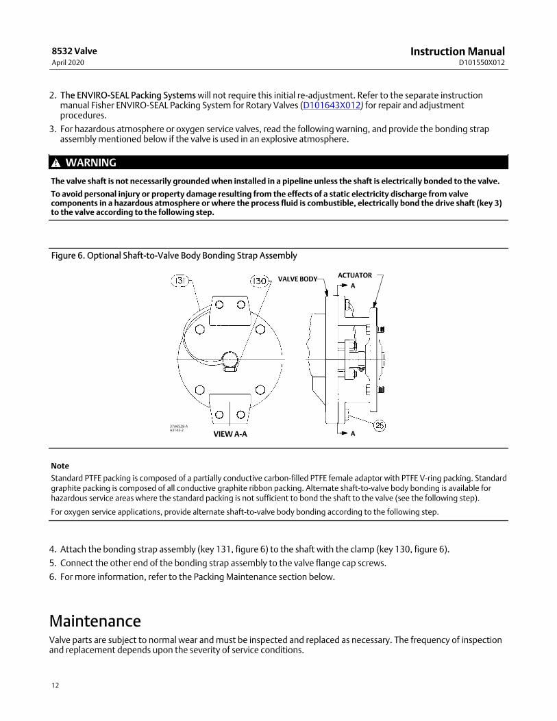
3. For hazardous atmosphere or oxygen service valves, read the following warning, and provide the bonding strapassembly mentioned below if the valve is used in an explosive atmosphere.
WARNING
The valve shaft is not necessarily grounded when installed in a pipeline unless the shaft is electrically bonded to the valve.
To avoid personal injury or property damage resulting from the effects of a static electricity discharge from valvecomponents in a hazardous atmosphere or where the process fluid is combustible, electrically bond the drive shaft (key 3)to the valve according to the following step.
Figure 6. Optional Shaft‐to‐Valve Body Bonding Strap Assembly
VALVE BODYACTUATOR
A
AVIEW A‐A37A6528‐AA3143‐2
Note
Standard PTFE packing is composed of a partially conductive carbon‐filled PTFE female adaptor with PTFE V‐ring packing. Standardgraphite packing is composed of all conductive graphite ribbon packing. Alternate shaft‐to‐valve body bonding is available forhazardous service areas where the standard packing is not sufficient to bond the shaft to the valve (see the following step).
For oxygen service applications, provide alternate shaft‐to‐valve body bonding according to the following step.
4. Attach the bonding strap assembly (key 131, figure 6) to the shaft with the clamp (key 130, figure 6).
5. Connect the other end of the bonding strap assembly to the valve flange cap screws.
6. For more information, refer to the Packing Maintenance section below.
MaintenanceValve parts are subject to normal wear and must be inspected and replaced as necessary. The frequency of inspectionand replacement depends upon the severity of service conditions.

Instruction ManualD101550X012
8532 ValveApril 2020
13
Key numbers in this procedure are shown in figures 10 and 11 unless otherwise indicated.
WARNING
Avoid personal injury from sudden release of process pressure. Before performing any maintenance operations:
� Do not remove the actuator from the valve while the valve is still pressurized.
� Always wear protective gloves, clothing, and eyewear when performing any maintenance operations to avoid personalinjury.
� Disconnect any operating lines providing air pressure, electric power, or a control signal to the actuator. Be sure theactuator cannot suddenly open or close the valve.
� Use bypass valves or completely shut off the process to isolate the valve from process pressure. Relieve process pressureon both sides of the valve. Drain the process media from both sides of the valve.
� Vent the power actuator loading pressure.
� Use lockout procedures to be sure that the above measures stay in effect while you work on the equipment.
� The valve packing box may contain process fluids that are pressurized, even when the valve has been removed from thepipeline. Process fluids may spray out under pressure when removing the packing hardware or packing rings, or whenloosening the packing box pipe plug.
� Check with your process or safety engineer for any other hazards that may be present from exposure to process media.
Removing and Replacing the ActuatorRefer to the appropriate actuator instruction manual for actuator removal and replacement procedures. The actuatorstops or travel stops must limit the rotation of the valve shaft. See the caution below.
CAUTION
When using an actuator, the actuator travel stop (or actuator travel, for actuators without adjustable stops) must beadjusted so the disk stop in the valve does not absorb the output of the actuator. Failure to limit the actuator travel canresult in damage to the valve, shaft(s), or other valve components.
Packing MaintenanceThe 8532 control valve is designed so the packing can be replaced without removing the valve from the processpipeline.
CAUTION
For non‐ENVIRO‐SEAL packing: Tighten the packing follower nuts only enough to prevent shaft leakage. Excessivetightening will accelerate wear of the packing and could produce higher friction loads on the valve stem.
Usually, packing leakage can be eliminated by merely tightening the hex nuts (key 15) located above the packingfollower (key 11) while the valve is in the pipeline. However, if leakage continues, the packing must be replaced.

Instruction ManualD101550X012
8532 ValveApril 2020
14
For PTFE ENVIRO‐SEAL packing systems, refer to the separate instruction manual, Fisher ENVIRO‐SEAL Packing Systemfor Rotary Valves (D101643X012) (see figure 12).
CAUTION
Never use a wrench or pliers on the splined (upper) shaft (key 3). A damaged shaft could cut the packing and allow leakage.
1. Before loosening any parts on the valve, release the pressure from the pipeline. Then, remove the hex nuts (key 15)and lift off the packing follower (key 11).
2. Remove the hex jam nuts (key 17) and the anti‐blowout flange (key 10). Remove the packing follower (key 12).Refer to figure 8 for details of the anti‐blowout design parts.
The packing is now accessible.
3. Use a packing extractor to remove packing. Insert the corkscrew‐like end of the tool into the first piece of packingand pull firmly to remove the packing. Repeat this process until all packing parts have been removed.
PACKING FLANGE
ANTI-BLOWOUTFLANGE
SHAFT SHOULDER
SHAFT
HEX NUT
STUD
PACKINGFOLLOWER
HEX NUT
TYPICAL PTFE V-RINGPACKING
HEX NUT
PACKINGFLANGE
SHAFTSHOULDER
STUD
HEX NUT
ANTI-BLOWOUTFLANGE
SPRING PACKASSEMBLY
PACKINGSET
ANTI-EXTRUSIONRING
PACKINGBOX RING
LUBRICANT
A7090
STANDARD PACKING ARRANGEMENT ENVIRO-SEAL ARRANGEMENT (PTFE SHOWN)
Figure 7. Blowout Protection NPS 14 through 24

Instruction ManualD101550X012
8532 ValveApril 2020
15
SHAFTSHOULDER
SHAFT
HEX NUTPACKINGFLANGE
SPRING PACKASSEMBLY
SHAFTSHOULDER
E1771
STANDARD PACKING ARRANGEMENT ENVIRO-SEAL ARRANGEMENT
Figure 8. Blowout Protection NPS 30 through 48
STUD
SHAFT
PACKINGFOLLOWER
TYPICALPTFEV-RINGPACKING
PACKINGBOX RINGANTI-
EXTRUSIONRING
PACKINGFLANGE
STUD
HEX NUT
PACKINGFOLLOWER
TYPICALPTFEV-RINGPACKING
PACKINGBOX RING
CAUTION
Be careful when cleaning the packing box. Scratches to the upper shaft (key 3) or inside diameter of the packing bore mightcause leakage.
4. Before installing new packing, clean the packing box.
5. Install new packing one ring at a time, using the packing follower as a driver. If using split‐ring packing, stagger thesplits in the rings to avoid creating a leak path.
6. Reinstall packing parts. Refer to figures 10 and 11 for sequence of packing parts.
Removing the Valve1. Disconnect any operating lines providing air pressure, electric power, or a control signal to the actuator. Be sure the
actuator cannot suddenly open the valve. Vent the power actuator loading pressure.
2. Use bypass valves or completely shut off the process to isolate the valve from process pressure. Relieve processpressure on both sides of the valve. Drain the process media from either side of the valve.
CAUTION
Damage to the valve disk can occur if the disk is not closed when the valve is being removed from the pipeline. If necessary,stroke the actuator to place the disk in the closed position while removing the valve from the pipeline.
3. Loosen the flange bolting that holds the valve. Make sure the valve cannot slip or twist while loosening andremoving the bolting.
4. Before removing the valve from the pipeline, make sure the valve disk is closed. Removing the valve with the diskopen could cause damage to the disk, piping, or pipe flanges.

Instruction ManualD101550X012
8532 ValveApril 2020
16
5. After removing the valve from the pipeline, move the valve to an appropriate work area. Always support the valveproperly.
6. When valve maintenance is complete, refer to the Installation procedures in this manual.
Seal Maintenance
Note
For larger valves, it is possible to replace the seal (key 5) while the actuator is mounted to the valve and can be accomplished bycycling the valve to 90 degrees open.
Key numbers in this procedure are shown in figures 10 and 11 unless otherwise indicated.
1. After removing the valve from the pipeline, remove the manual or power actuator. Manually rotate the upper shaft(key 3) counterclockwise until the disk has moved a full 180 degrees away from the closed position.
WARNING
Avoid personal injury or property damage caused by the impact of a falling or tipping of a large valve. Support large valvesduring maintenance.
2. Lay the valve flat on a work bench in a secure position with the retaining ring (key 18) and retaining ring screws (key 19) facing up. Properly secure the valve on a suitable worktable so it cannot slip, twist, or fall duringmaintenance. Remove all retaining ring screws.
3. Remove the retaining ring by placing a socket head cap screw from the retaining ring in each of the two retainingring jacking screw holes. Slowly turn the screws until the retaining ring has been lifted from the valve body. Removethe retaining ring to expose the seal in the T‐slot area of the valve body.
Note
The 8532 valve is available with different seal designs and components. See figure 2 to identify the specific seal design.
CAUTION
In the following procedure, take care not to damage the seal or T‐slot area of the valve body during removal of the seal.
4. Insert a regular screwdriver or other similar tool under the top edge of the seal and gently pry the seal out of theT‐slot area in the valve body. Take care not to damage the seal or T‐slot area of the valve body. After the seal hasbeen removed, clean the T‐slot area, retaining ring and, if required, polish the disk (key 2) thoroughly with fine steelwool or other appropriate material.
To install a new seal, O‐ring (key 6), and retaining ring gasket, follow the appropriate instructions given below.

Instruction ManualD101550X012
8532 ValveApril 2020
17
Table 7. Torque Values for Fasteners
FASTENER NOMINAL SIZERETAINING RING SCREWS GASKET RETAINING BOLTS(1)
N�m In�lbs N�m In�lbs
#10 4.6 41 4.0 35
1/4 11 100 9.2 81
5/16 25 220 19 167
3/8 45 400 33 295
N�m ft�lbs N�m ft�lbs
7/16 72 53 53 39
1/2 112 83 80 59
9/16 161 119 117 86
5/8 225 166 161 119
3/4 401 296 286 210
7/8 651 480 447 330
1 976 720 651 480
1‐1/8 1356 1000 837 617
1. Torque values provided for gasket retaining bolting require lubrication of threads with a dry film lubricant. Use of other lubricants may change torque recommendation.Note: These values are based upon standard materials, S66286/N07718 screws and ASTM A193GRB6 bolts. For other special fastener materials, please contact your Emerson sales office.
PTFE Seals1. Locate the replacement seal ring (key 5) and note the shape of the ring. The ring is wider across one edge diameter
and narrower across the other edge diameter. Around the outside circumference is one wide groove.
Before installing the seal ring into the valve body, place the O‐ring (key 6) into the wide, outer groove of the seal ring.Refer to figure 9.
2. Install the seal ring and O‐ring assembly in the valve body. The wider outside diameter of the seal ring goes into theT‐slot area of the body (see figure 5). Start the edge with the wider diameter into the T‐slot of the valve body using ablunt‐end screwdriver. If you have a maintenance kit, use the seal installation tools.
Figure 9. Typical Seal Installation
A5251‐1
LARGEST OUTSIDEDIAMETER (KEY 5)
INTERNALTRAVEL STOP
3. Carefully tuck the O‐ring downward into the body T‐slot until the seal ring is completely entrapped in the bodyT‐slot, and it completely covers the backup O‐ring.

Instruction ManualD101550X012
8532 ValveApril 2020
18
4. Re‐install the retaining ring and the socket head cap screws. Tighten the cap screws just enough to eliminate anymovement of the retaining ring. Do not over‐tighten the retaining ring screws. Using a blunt‐end tool, carefullytuck the lip of the seal ring under the retaining ring.
5. When the seal is under the lip of the retaining ring, continue to tighten the cap screws according to standardprocedures. Do not fully torque the screws at this time. Final tightening of the screws is accomplished in step 7 ofthis procedure.
6. Manually rotate the upper shaft clockwise 180 degrees to return the disk (key 2) to its closed position.
7. The final seating of the retaining ring cap screws can now be done. For the screw torque values, refer to table 7. Theseal is now fully installed. Refer to the Installation procedures in this manual.
NOVEX, Phoenix III and/or Phoenix III Fire‐Tested Seals1. Locate the replacement seal ring (key 5) and note the shape of the ring. The ring is wider across one edge diameter
and narrower across the other edge diameter as shown in figure 9. Around the outside circumference is one widegroove.
Install the seal ring (key 5) in the valve body by first placing the wider outside diameter of the seal ring into the T‐slotarea of the valve body which is shown in figure 2.
The backup O‐ring (key 6) for the Phoenix III seal will have to be installed after placement of the seal ring in the valvebody using a blunt‐end screwdriver or the seal installation tool in the maintenance kit. Do not use the screwdriver orseal tool directly on the metal seat. Use tools on the O‐ring only.
2. With the seal ring inserted all the way around the body T‐slot now lay the O‐ring into the opening between the valvebody and the seal ring. Use the seal tool to apply pressure to the O‐ring and carefully tuck the O‐ring down into theT‐slot between the valve body and the seal ring.
Note
On larger valves, it may be more efficient to have someone hold down the seal ring while you push the O‐ring into the T‐slot.
3. Once the seal ring and backup O‐ring have been fully installed into the body T‐slot, the retaining ring gasket can beinstalled. This gasket is a thin graphite material. Punch one initial screw hole through the gasket for alignment,being careful not to cause additional damage to the gasket.
4. Install the retaining ring and align the screw holes in the retaining ring with the holes in the valve body. Install thefirst retaining ring screw through the punched hole in the ring gasket. Install the other ring screws by pushing thescrews through the graphite gasket and threading them into the valve body.
5. Tighten the retaining ring socket head cap screws just enough to eliminate any movement of the retaining ring. Donot over‐tighten the retaining ring screws.
WARNING
Avoid personal injury or property damage caused by the impact of a falling or tipping of a large valve. Support large valvesduring maintenance.
6. To complete this step, stand the valve up. Support the valve securely using methods appropriate for the valve size.If a vise or other clamps are being used, be sure to not damage the flange gasket sealing area of the valve body.
7. Manually rotate the upper shaft (key 3) to turn the disk clockwise to meet the seal.

Instruction ManualD101550X012
8532 ValveApril 2020
19
8. Tap the disk with a rubber mallet to drive it against the internal travel stop. When the disk makes contact with thestop, manually rotate the disk counterclockwise back out of the seal to a 90‐degree open position. Repeat steps 7and 8 three times.
Note
When attaching the actuator to the valve, make sure the valve disk is not in contact with the valve internal travel stop (see figure 9). The valve disk should be positioned from 0 to 0.76 mm (0 to 0.030 inch) away from the internal stop in the valve body(see figure 9).
9. Use an appropriate tool (such as a feeler gauge) to position the disk (key 2) from 0 to 0.76 mm (0 to 0.030 inch)away from the internal stop in the valve body.
This adjustment is necessary to be certain that the actuator output torque is fully absorbed by the actuator travel stopor by the actuator. The internal travel stop in the valve body should not absorb any of the actuator torque.
10. The final seating of the retaining ring screws can now be done. For the screw torque values, refer to table 7.
Anti‐Blowout Design, Packing, Valve Shaft, Disk, and BearingMaintenance
Note
The 8532 valve has a two‐piece shaft. In these procedures, the shaft (with the splined end) is called the upper shaft (key 3). Theshaft opposite the upper shaft is called the lower (follower) shaft (key 4).
CAUTION
When using an actuator, the actuator travel stop (or actuator travel adjustment, for actuators without adjustable stops)must be adjusted so the disk stop in the valve does not absorb the output of the actuator. Failure to limit the actuator travelas described in the next step can result in damage to the valve, shaft(s), or other valve components.
CAUTION
When removing the actuator from the valve, do not use a hammer or similar tool to drive the lever off the valve shaft.Driving the lever or actuator off the valve shaft could damage the valve internal parts.
If necessary, use a wheel puller to remove the lever or actuator from the valve shaft. It is okay to tap the wheel puller screwlightly to loosen the lever or actuator, but hitting the screw with excessive force could also damage internal valve parts.
Key numbers in this procedure are shown in figures 10 and 11 unless otherwise indicated.
1. Remove the valve from the pipeline. Remove the actuator from the valve.
CAUTION
Never use a wrench, pliers, or similar tool to turn the upper shaft. A damaged shaft can cut the packing and allow leakage.

Instruction ManualD101550X012
8532 ValveApril 2020
20
Note
It is not necessary to remove the retaining ring and valve seal when removing the shaft(s) and disk.
WARNING
Avoid personal injury or property damage caused by the impact of a falling or tipping of a large valve. Support large valvesduring maintenance.
2. Properly secure the valve on a suitable worktable so it cannot slip, twist, or fall during maintenance.
3. Removing the Anti‐Blowout Design:
a. For PTFE or Graphite Packing: Remove the hex nuts (key 15) and pull off the packing follower (key 11). Removethe hex jam nuts (key 17) and the anti‐blowout flange (key 10). Remove the anti‐blowout gland (key 12). Seefigure 8.
b. For ENVIRO‐SEAL Packing System: Remove the hex nuts (key 101), the packing follower (key 102), jam nuts (key17), anti‐blowout flange (key 10), and the spring pack assembly (key 103). See figure 12.
4. Remove the packing from around the upper shaft.
5. Remove the tangential pins or disk pins. Locate the pins (key 9) in the upper shaft (key 3) and the pin in the lowershaft (key 4), if the valve has a two‐piece shaft.
a. If a maintenance kit is available, use the pin extractor to remove the disk pins. Select the correct size pin extractortip with screws of proper thread size to match the thread size in the disk pins. If you do not have a kit, see steps cand d below.
b. Screw the pin extractor tip into the pin as far as possible. With an upward, straight sliding motion, pull out thepin. Repeat the same procedure for the other pins.
c. You can use a threaded rod with an appropriate spacer (tube) and nut as an extractor tool. If you use a threadedrod, choose a rod with threads that fit the inside thread of the pins. The rod should extend several inches abovethe disk when it is screwed into a pin.
d. After screwing the rod into the pin, slide the spacer over the rod and pin. Thread a nut onto the rod and tightenit. As you tighten the nut, the nut will drive the spacer against the disk. The increasing force will draw the pinfrom the disk.
6. The gasket retainer (key 20) on the side of the valve opposite the upper shaft must be removed before removingthe lower shaft.
Remove the hex head bolts (key 23) and lockwashers (key 22) from the gasket retainer and remove the gasket retainerand gasket (key 21) to expose the end of the lower shaft.
7. Before removing the lower shaft (key 4), be sure the valve disk is properly supported. Pull the lower shaft from thevalve body. Use a shaft extractor screwed into the puller hole in the end of the lower shaft.
8. Before removing the upper shaft (key 3), be sure the valve disk is properly supported. Pull out the upper shaft (key 3) by hand‐pulling or by using a shaft extractor screwed into the end of the shaft.
CAUTION
To avoid damage to the disk, seal, and T‐slot area, do not force the disk past the seal or T‐slot area. Remove the disk fromthe opposite side of the valve body.

Instruction ManualD101550X012
8532 ValveApril 2020
21
Note
Both the upper shaft and the lower shaft have a thrust bearing (key 24) between the disk and the bearings (key 7). The thrustbearing is located outside of the bearing bore which holds the bearings. Use care when removing the valve disk to avoid loss of ordamage to the thrust bearings.
9. After removing the shaft(s), remove the disk. Do not force the disk past the seal or T‐slot area. Collect the thrustbearings.
10. Remove the bearings (key 7). Using a suitable punch or puller, drive or pull the bearings into the valve body borefrom the upper shaft bearing bore. Remove the bearing from the lower shaft bearing bore.
11. Inspect the valve body bore, bearings, bearing bores, and packing box for damage.
Note
In these instructions, the drive shaft (with splined end) is called the upper shaft (key 3). The shaft opposite the upper shaft is calledthe lower (follower) shaft (key 4).
Installing the Two‐Piece Shaft
Key numbers in this procedure are shown in figures 10 and 11 unless otherwise indicated.
WARNING
Avoid personal injury or property damage caused by the impact of a falling or tipping of a large valve. Support large valvesduring maintenance.
1. Properly secure the valve on a suitable worktable so it cannot slip, twist, or fall during maintenance. Be prepared tosupport the valve disk.
Note
Replacement disk and shafts are provided as a matched set and both should be replaced at the same time.
2. Inspect all parts removed from the valve for wear or damage. Replace any worn or damaged parts. Clean the valvebody and all parts to be installed with an appropriate solvent or degreaser.
Note
When installing the bearings, apply lubricant to the outside diameter of the bearing for ease of installation.
CAUTION
Premature valve failure and loss of process control may result if bearings are improperly installed or are damaged duringinstallation.
3. When installing the lower bearings (key 4), insert one or more bearings into the lower shaft bearing bore so it isflush with the body bore.
The number of bearings required changes with valve size and construction. Two bearings are required in the uppershaft and two bearings in the lower shaft. If using an NPS 14 CL150 valve with metal bearings, four bearings in theupper and four in the lower shaft will be required.

Instruction ManualD101550X012
8532 ValveApril 2020
22
4. Hold the lower shaft thrust bearing (key 24) in the valve body bore against the counterbore of the lower shaftbearing bore. Push the lower shaft into the bearing bore just enough to hold the thrust bearing.
5. When installing the upper bearing (key 7), insert one or more bearings into the upper shaft from the body bore intothe bearing bore below the packing box. Use caution to prevent damage to the bearing.
6. Hold the upper shaft thrust bearing (key 24) in the valve body bore against the counterbore of the upper shaftbearing bore. Push the upper shaft through the packing box side into the bearing bore just enough to hold thethrust bearing.
7. When installing the lower bearing (key 4), insert one or more bearings into the lower shaft bearing bore so it is flushwith the body bore.
8. Insert the lower shaft through the bore in the valve body uncovered by removal of the gasket retainer. Hold thelower shaft thrust bearing (key 24) in the valve body bore against the counterbore of the lower shaft bearing bore.Push the lower shaft into the bearing bore just enough to hold the thrust bearing.
CAUTION
To avoid damage to the disk, seal, and T‐slot area, do not force the disk past the seal or T‐slot area. Install the disk from theopposite side of the valve body.
9. Place the flat side of the disk on a flat surface and insert wooden blocks to raise the disk approximately 51 mm (2 inches) from the worktable surface. Then, suspend the valve body over the disk so the seal/T‐slot area is facingup. Align the shaft bores through the disk with the upper shaft and lower shaft bores. Lower the valve body over thedisk using caution not to dislodge or damage the thrust bearings placed on the ends of the shafts.
10. With the disk (key 2) properly positioned in the valve body (key 1), push the upper shaft and lower shaft the rest ofthe way through the thrust bearings and into the shaft bores in the valve disk.
11. Align the holes in the shafts with the holes in the disk.
CAUTION
To avoid damage to the tangential pins, disk pins, valve disk, or shaft(s) resulting from the application of excessive force,use appropriate care when driving the pins into the disk hub and shaft(s). Use the right tool. Do not use excessive force.
12. Install the appropriate tangential pins, and disk pins. Use 2 tangential pins that will go through the upper shaft and 1 disk pin that will go through the lower shaft.
13. Refer to the Anti‐Blowout Design, Packing, Valve Shaft, Disk and Bearing Maintenance procedures in this manual tore‐install the packing and anti‐blowout design.
Gasket RetainerValves with a two‐piece shaft use a gasket retainer and gasket (keys 20 and 21) to cover the lower shaft opening in thevalve body. The gasket is held in place by the gasket retainer and four hex head bolts and lockwashers (keys 23 and 22). When re‐assembling the valve, use a new gasket.
Be sure to center the gasket over the lower shaft bore before retightening bolts. Tighten down bolts evenly in acrossover or star pattern.
Refer to table 7 for proper torque values.

Instruction ManualD101550X012
8532 ValveApril 2020
23
Parts OrderingTypical parts are shown in figures 10 and 11.
When corresponding with your Emerson sales office about an 8532 valve, identify the valve as a Fisher 8532 andprovide the valve serial number. For valve/actuator combinations assembled at the factory, the valve serial numbermay be stamped on the nameplate attached to the actuator.
WARNING
Use only genuine Fisher replacement parts. Components that are not supplied by Emerson Automation Solutions shouldnot, under any circumstances, be used in any Fisher valve, because they may void your warranty, might adversely affect theperformance of the valve, and could cause personal injury and property damage.
Retrofit KitsRetrofit kits include all parts required for installation of the ENVIRO‐SEAL packing system into existinghigh‐performance butterfly valves. Retrofit kits are available for single PTFE packing.
See table 8 for retrofit kit part numbers.
Retrofit Kit Included Parts
Key Description Quantity
1017
100101102103105106107111112
Anti‐blowout followerJam nut
Packing studPacking nut
Packing flangeSpring pack assembly
Packing SetAnti‐extrusion washer
Packing box ringTag
Cable
1122111
2(1)
2(2)
11
1. Not included in graphite packing kit.2. Only 1 req'd for NPS 18 CL300, NPS 20 CL150 and NPS 24 CL150.
Note
Key 103, the spring pack assembly, is made up of the packing spring stack held in place by an O‐ring on the packing follower.

Instruction ManualD101550X012
8532 ValveApril 2020
24
Repair KitsPTFE Repair kits include a single PTFE packing set and anti‐extrusion washers. Graphite packing sets include graphitepacking rings and carbon anti‐extrusion rings. See table 8 for PTFE repair kit part numbers.
Table 8. Retrofit and Repair Kit Part Numbers
VALVE SIZE, NPS PRESSURE RATINGSHAFT
DIAMETER(1)(2),mm (Inch)
RETROFIT KITS REPAIR KITS
PTFE PTFE
14CL150 34.9 (1‐3/8) RRTYXRT0592 RRTYX000172
CL300 50.8 (2) RRTYXRT0602 RRTYX000182
16CL150 38.1 (1‐1/2) RRTYXRT0612 RRTYX000192
CL300 57.2 (2‐1/4) RRTYXRT0622 RRTYX000202
18CL150 44.5 (1‐3/4) RRTYXRT0632 RRTYX000212
CL300 63.5 (2‐1/2) RRTYXRT0642 RRTYX000222
20 CL150 50.8 (2) RRTYXRT0652 RRTYX000182
24 CL150 63.5 (2‐1/2) RRTYXRT0662 RRTYX000222
1. Shaft diameter: Diameter through the packing box.2. For larger shaft sizes, consult your Emerson sales office.

Instruction ManualD101550X012
8532 ValveApril 2020
25
Parts List
Note
Contact your Emerson sales office for Part Ordering information.
Key Description
1 Valve Body
2* Disk
3* Drive Shaft
4* Follower Shaft
�5* Seal Ring
�6* Backup Ring
�7* Bearing
9* Disk Pin
10 Anti‐Blowout Flange (Not used in NPS 30-48)
11 Packing Flange
12 Packing Follower
13* Packing Set
14 Stud (2 req'd)
15 Hex nut (2 req'd)
17 Hex Jam Nut (2 req'd)
18 Retaining Ring
19 Retaining Ring Screw (8 req'd)
20 Gasket Retainer
Key Description
21* Gasket
22 Lockwasher (4 req'd)
23 Cap Screw (4 req'd)
24* Thrust Bearing
26* Retaining Ring Gasket
27 Cap Screw - Actuator (4 req'd) (not shown)
28 Hex Nut - Actuator (4 req'd) (not shown)
29 Nameplate (not shown)
32 Drive Screw (2 req'd)
33 Flow Direction Arrow (not shown)
34 Packing Box Ring
35* Disk/Shaft/Pin Assembly (not shown)
ENVIRO‐SEAL Packing System(See figure 12)10 Anti‐Blow Flange
17 Hex Jam Nut (4 req'd)
100 Packing Flange Stud (4 req'd)
101 Packing Flange Nut (4 req'd)
102 Packing Flange
103 Spring Pack Assembly
105* Packing Set
106* Anti‐Extrusion Ring (2 req'd)
107 Packing Box Ring
111 Tag (not shown)
112 Cable Tie (not shown)
113 Lubricant
*Recommended spare parts
Instruction ManualD101550X012
8532 ValveApril 2020
26
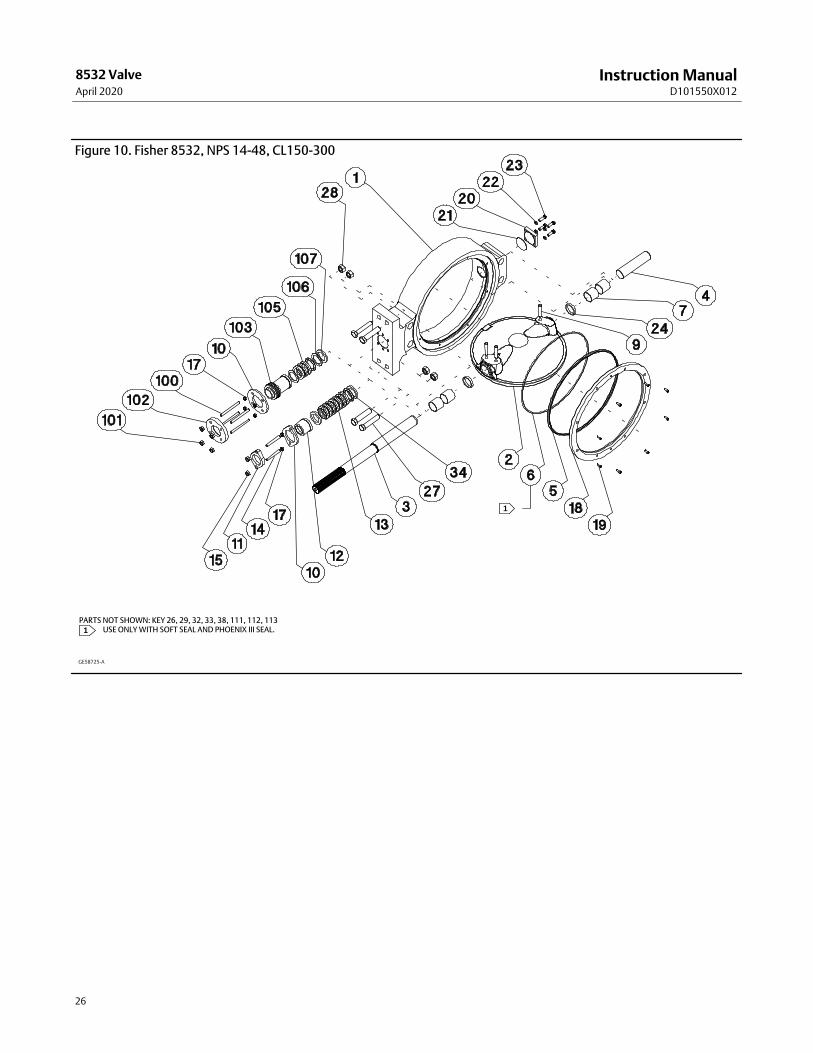
Figure 10. Fisher 8532, NPS 14-48, CL150-300
GE58725-A
PARTS NOT SHOWN: KEY 26, 29, 32, 33, 38, 111, 112, 113���USE ONLY WITH SOFT SEAL AND PHOENIX III SEAL.1
1

Instruction ManualD101550X012
8532 ValveApril 2020
27
Figure 11. Fisher 8532, NPS 14-24, CL150-300, Double Flange Valve Body
GE58760-A
PARTS NOT SHOWN: KEY 26, 29, 32, 33, 38, 111, 112, 113���USE ONLY WITH SOFT SEAL AND PHOENIX III SEAL.1
1

Instruction ManualD101550X012
8532 ValveApril 2020
28
Figure 12. ENVIRO‐SEAL Packing Systems
PTFE PACKING SYSTEM
34B7524‐B
STACKING ORDER OFPTFE PACKING RINGS
14B0095‐A
1
14B0086‐A
34B7524‐B
GRAPHITE PACKING SYSTEM
STACKING ORDER OFGRAPHITE PACKING RINGS
NOTE:
VALVES WITH SHAFTS LARGER THAN 38.1 mm (1-1/2 INCH) USE GRAPHITE RINGS
Emerson Automation SolutionsMarshalltown, Iowa 50158 USASorocaba, 18087 BrazilCernay, 68700 FranceDubai, United Arab EmiratesSingapore 128461 Singapore
www.Fisher.com
The contents of this publication are presented for informational purposes only, and while every effort has been made to ensure their accuracy, they are notto be construed as warranties or guarantees, express or implied, regarding the products or services described herein or their use or applicability. All sales aregoverned by our terms and conditions, which are available upon request. We reserve the right to modify or improve the designs or specifications of suchproducts at any time without notice.
� 1990, 2020 Fisher Controls International LLC. All rights reserved.
Fisher and ENVIRO-SEAL are marks owned by one of the companies in the Emerson Automation Solutions business unit of Emerson Electric Co. EmersonAutomation Solutions, Emerson, and the Emerson logo are trademarks and service marks of Emerson Electric Co. All other marks are the property of theirrespective owners.
Neither Emerson, Emerson Automation Solutions, nor any of their affiliated entities assumes responsibility for the selection, use or maintenanceof any product. Responsibility for proper selection, use, and maintenance of any product remains solely with the purchaser and end user.