fisher gx control valve and actuator system control valve and actuator d103171x012 product bulletin...
TRANSCRIPT

www.Fisher.com
Fisher™ GX Control Valve and Actuator SystemThe Fisher GX is a compact, state-of-the-art controlvalve and actuator system, designed to control a widerange of process liquids, gases, and vapors.
The GX is rugged, reliable, and easy to select. Itrequires no actuator sizing -- the actuator selection isautomatic once the valve body construction isselected.
The optimized design results in reduced complexityand parts count. As a result, the cost of maintenance isreduced.
The GX meets the requirements of both EN and ASMEstandards. It is available with a complete accessorypackage, including the Fisher FIELDVUE™ DVC2000and DVC6200 integrated digital valve controllers.
Features� Easy to size and select
� No actuator sizing required--selection is automatic
� Optimized actuator allows for a wide range of airsupply
� Engineered for easy maintenance
� Maximum part commonality across sizes
� Replaceable trim
� Low lifetime costs
� Robust, low-profile design
� Compact multi-spring pneumatic actuator
� Available with integrated, easy-to-calibrateDVC2000 or DVC6200 digital valve controller
W8861-2 Fisher GX Control Valve, Actuator, and FIELDVUE DVC2000 Digital Valve Controller
� Valve body sizes DN 15 to DN 150 (NPS 1/2 through 6)
� Pressure Classes PN 10-40, CL150 and 300
� High capacity design
� Valve body flow passage optimized for flowstability
� Full range of materials, including alloys
� Shutoff capabilities: Class IV, V, and VI
� Rangeability of 50:1 (equal percentage)
� Optional metal bellows seal
� ISO 5210 F7 mounting available for use with electricactuators
GX Control Valve and ActuatorD103171X012
Product Bulletin51.1:GX
May 2019

GX Control Valve and ActuatorD103171X012
Product Bulletin51.1:GXMay 2019
2
W8568-1A
COMPACT FIELD-REVERSIBLEMULTI-SPRING ACTUATOR
INTEGRATED POSITIONERMOUNTING
NAMUR POSITIONERMOUNTING CAPABILITY
ONE-PIECE SCREWEDPACKING FOLLOWER
CLAMPED BONNET DESIGN
STANDARD ENVIRO-SEAL™ PACKING
INTEGRAL PNEUMATIC PASSAGEWAYS
Figure 1. Fisher GX Control Valve Assembly with Port-Guided Contoured Plug (Port Sizes 36 to 136 mm)
Optimized valve and actuator system—Productsimplicity and ease of selection form the foundation ofthe GX. Mounted with a digital or analog positioner,the GX provides high performance control across awide range of process applications.
Compact actuator design—The GX utilizes a compact,multi-spring actuator. The GX design has beenoptimized to eliminate complicated actuator sizingprocedures - once the valve body, port size, and airsupply pressure are selected, the actuator size is fixed.
Modular design—The design architecture has beenoptimized to maximize the use of common partsacross sizes. The actuator stem and stem connectorare used across all GX sizes. The GX actuator uses atotal of 5 different springs across all valve sizes. Thesespring sets have been optimized to allow for maximumapplication coverage. The plug/stem assemblies andENVIRO-SEAL packing sets are common across severalsizes, as well.
ContentsFeatures 1. . . . . . . . . . . . . . . . . . . . . . . . . . . . . . . . . . . . .Principle of Operation 4. . . . . . . . . . . . . . . . . . . . . . . . .The Fisher GX Control Valve 6. . . . . . . . . . . . . . . . . . . .Fisher GX Control Valve Specifications
and Materials of Construction 7. . . . . . . . . . . . . . . .GX Cavitrol� III for DN25 (NPS 1) through
DN50 (NPS 2) 15. . . . . . . . . . . . . . . . . . . . . . . . . . . . .GX Whisper Trim� III for DN80 (NPS 3) through
DN150 (NPS 6) 15. . . . . . . . . . . . . . . . . . . . . . . . . . . .
The Fisher GX Diaphragm Actuator 16. . . . . . . . . . . . .GX ISO 5210 Electric Actuator Mounting 17. . . . . . . . .Bellows Extension Bonnet 17. . . . . . . . . . . . . . . . . . . . .Valve-Actuator Dimensions and Weights 22. . . . . . . . .Fisher GX Actuator Accessories 25. . . . . . . . . . . . . . . . .The Fisher FIELDVUE DVC2000
Digital Valve Controller 25. . . . . . . . . . . . . . . . . . . . .Optional Positioners and Instruments 26. . . . . . . . . . .Manual Handwheels 27. . . . . . . . . . . . . . . . . . . . . . . . . .
GX Control Valve and ActuatorD103171X012
Product Bulletin51.1:GX
May 2019
3
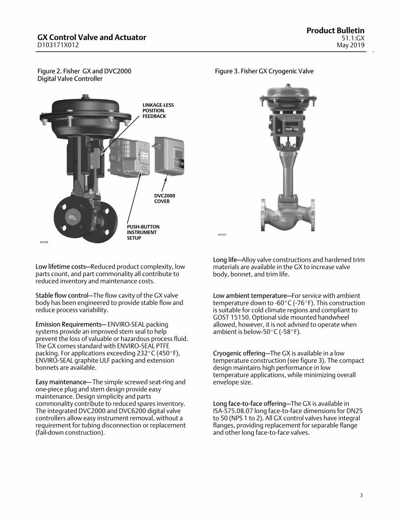
Figure 2. Fisher GX and DVC2000 Digital Valve Controller
LINKAGE-LESSPOSITIONFEEDBACK
PUSH-BUTTONINSTRUMENTSETUP
W8588
DVC2000COVER
Low lifetime costs—Reduced product complexity, lowparts count, and part commonality all contribute toreduced inventory and maintenance costs.
Stable flow control—The flow cavity of the GX valvebody has been engineered to provide stable flow andreduce process variability.
Emission Requirements— ENVIRO-SEAL packingsystems provide an improved stem seal to helpprevent the loss of valuable or hazardous process fluid.The GX comes standard with ENVIRO-SEAL PTFEpacking. For applications exceeding 232�C (450�F),ENVIRO-SEAL graphite ULF packing and extensionbonnets are available.
Easy maintenance— The simple screwed seat-ring andone-piece plug and stem design provide easymaintenance. Design simplicity and partscommonality contribute to reduced spares inventory.The integrated DVC2000 and DVC6200 digital valvecontrollers allow easy instrument removal, without arequirement for tubing disconnection or replacement(fail-down construction).
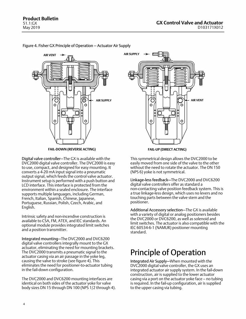
Figure 3. Fisher GX Cryogenic Valve
W9343
Long life—Alloy valve constructions and hardened trimmaterials are available in the GX to increase valvebody, bonnet, and trim life.
Low ambient temperature—For service with ambienttemperature down to -60�C (-76�F). This constructionis suitable for cold climate regions and compliant toGOST 15150. Optional side mounted handwheelallowed, however, it is not advised to operate whenambient is below-50�C (-58�F).
Cryogenic offering—The GX is available in a lowtemperature construction (see figure 3). The compactdesign maintains high performance in lowtemperature applications, while minimizing overallenvelope size.
Long face-to-face offering—The GX is available inISA-S75.08.07 long face-to-face dimensions for DN25to 50 (NPS 1 to 2). All GX control valves have integralflanges, providing replacement for separable flangeand other long face-to-face valves.
GX Control Valve and ActuatorD103171X012
Product Bulletin51.1:GXMay 2019
4
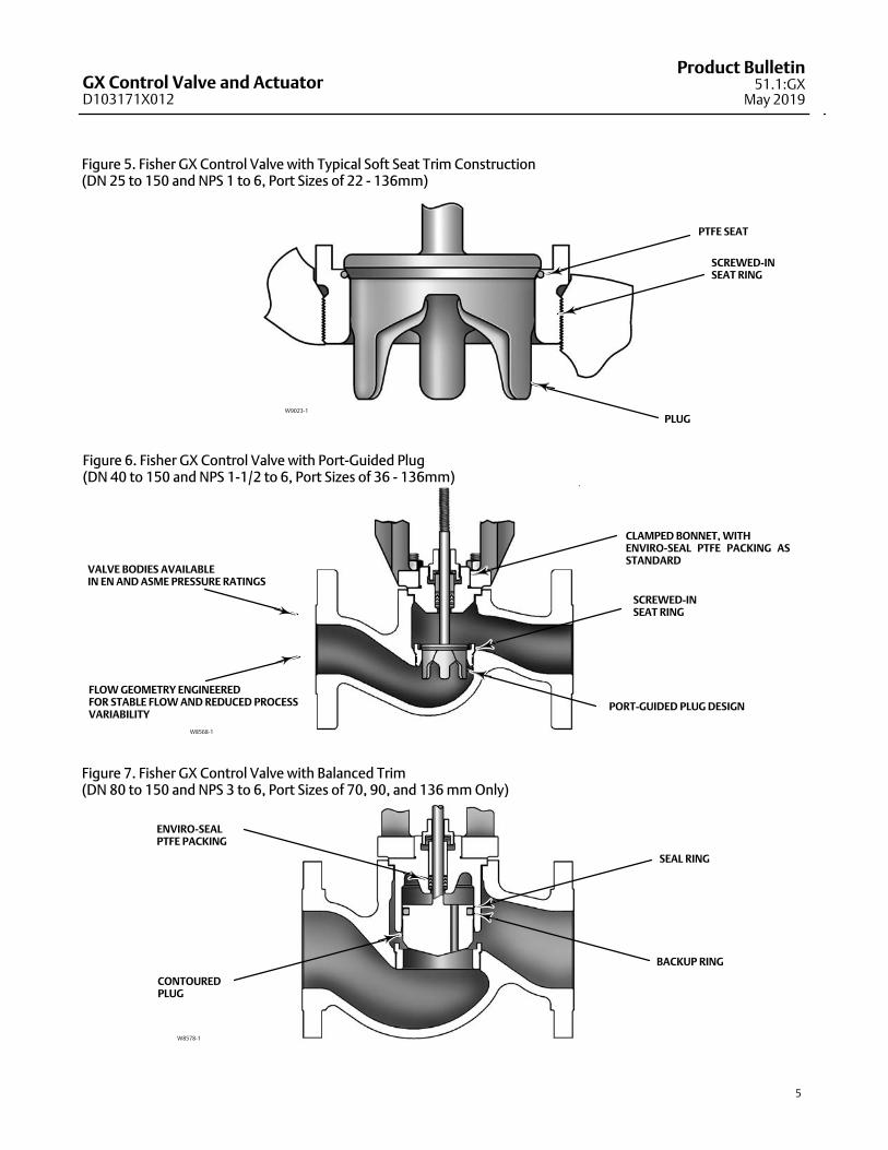
Figure 4. Fisher GX Principle of Operation -- Actuator Air Supply
FAIL-DOWN (REVERSE ACTING) FAIL-UP (DIRECT ACTING)
AIR SUPPLY
AIR SUPPLY
AIR VENT
AIR VENT
Digital valve controller—The GX is available with theDVC2000 digital valve controller. The DVC2000 is easyto use, compact, and designed for easy mounting. Itconverts a 4-20 mA input signal into a pneumaticoutput signal, which feeds the control valve actuator.Instrument setup is performed with a push button andLCD interface. This interface is protected from theenvironment within a sealed enclosure. The interfacesupports multiple languages, including German,French, Italian, Spanish, Chinese, Japanese,Portuguese, Russian, Polish, Czech, Arabic, andEnglish.
Intrinsic safety and non-incendive construction isavailable to CSA, FM, ATEX, and IEC standards. Anoptional module provides integrated limit switchesand a position transmitter.
Integrated mounting—The DVC2000 and DVC6200digital valve controllers integrally mount to the GXactuator, eliminating the need for mounting brackets.The DVC2000 transmits a pneumatic signal to theactuator casing via an air passage in the yoke leg,causing the valve to stroke (see figure 4). Thiseliminates the need for positioner-to-actuator tubingin the fail-down configuration.
The DVC2000 and DVC6200 mounting interfaces areidentical on both sides of the actuator yoke for valvebody sizes DN 15 through DN 100 (NPS 1/2 through 4).
This symmetrical design allows the DVC2000 to beeasily moved from one side of the valve to the otherwithout the need to rotate the actuator. The DN 150(NPS 6) yoke is not symmetrical.
Linkage-less feedback—The DVC2000 and DVC6200digital valve controllers offer as standard anon-contacting valve position feedback system. This isa true linkage-less design, which uses no levers and notouching parts between the valve stem and thepositioner.
Additional Accessory selection—The GX is availablewith a variety of digital or analog positioners besidesthe DVC2000 or DVC6200, as well as solenoid andlimit switches. The actuator is also compatible with theIEC 60534-6-1 (NAMUR) positioner mountingstandard.
Principle of OperationIntegrated Air Supply—When mounted with theDVC2000 digital valve controller, the GX uses anintegrated actuator air supply system. In the fail-downconstruction, air is supplied to the lower actuatorcasing via a port on the actuator yoke face -- no tubingis required. In the fail-up configuration, air is suppliedto the upper casing via tubing.
GX Control Valve and ActuatorD103171X012
Product Bulletin51.1:GX
May 2019
5
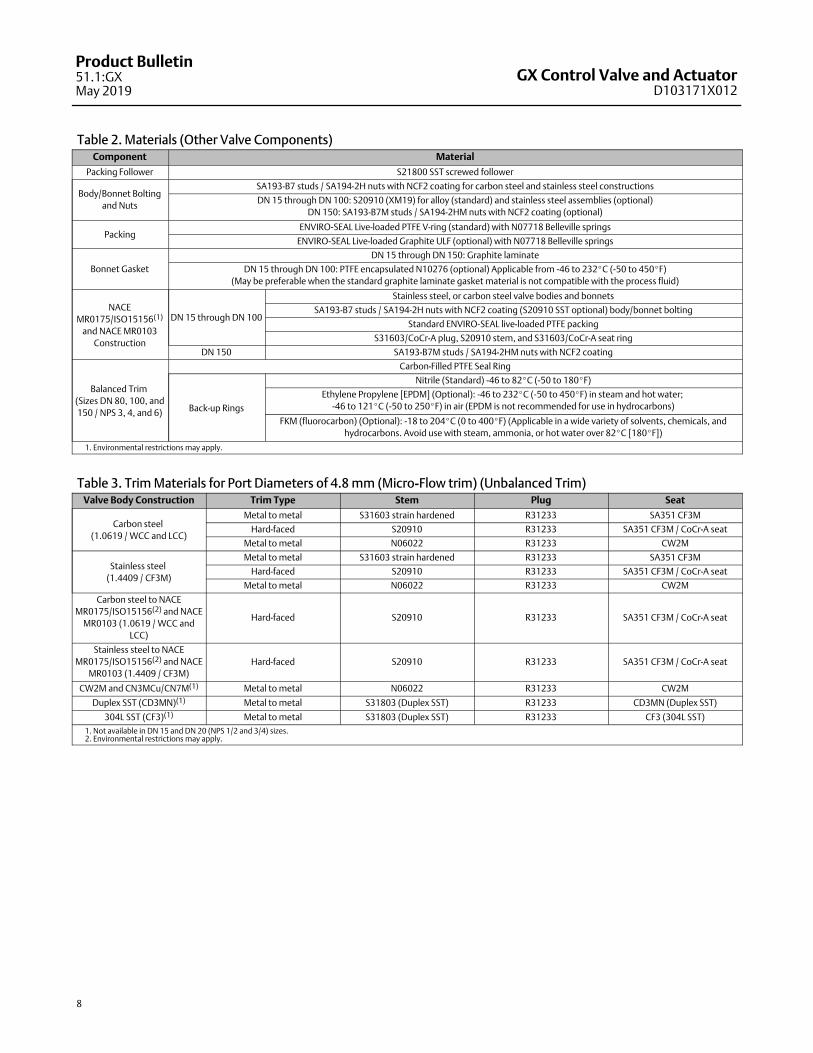
PLUG
SCREWED-INSEAT RING
PTFE SEAT
W9023-1
Figure 5. Fisher GX Control Valve with Typical Soft Seat Trim Construction (DN 25 to 150 and NPS 1 to 6, Port Sizes of 22 - 136mm)
W8568-1
CLAMPED BONNET, WITHENVIRO-SEAL PTFE PACKING ASSTANDARD
PORT-GUIDED PLUG DESIGN
VALVE BODIES AVAILABLEIN EN AND ASME PRESSURE RATINGS
FLOW GEOMETRY ENGINEEREDFOR STABLE FLOW AND REDUCED PROCESSVARIABILITY
SCREWED-INSEAT RING
Figure 6. Fisher GX Control Valve with Port-Guided Plug(DN 40 to 150 and NPS 1-1/2 to 6, Port Sizes of 36 - 136mm)
Figure 7. Fisher GX Control Valve with Balanced Trim (DN 80 to 150 and NPS 3 to 6, Port Sizes of 70, 90, and 136 mm Only)
CONTOUREDPLUG
SEAL RING
BACKUP RING
ENVIRO-SEALPTFE PACKING
W8578-1

GX Control Valve and ActuatorD103171X012
Product Bulletin51.1:GXMay 2019
6
Figure 8. Fisher GX Control Valve Assembly with Stem-Guided Contoured Plug (Size DN 25 and NPS 1)
W8486-3
COMPACT FIELD-REVERSIBLEMULTI-SPRING ACTUATOR
INTEGRATED POSITIONERMOUNTING
NAMUR POSITIONERMOUNTING CAPABILITY
ONE-PIECE SCREWEDPACKING FOLLOWER
CLAMPED BONNET DESIGN
STANDARD ENVIRO-SEAL PACKING
INTEGRAL PNEUMATIC PASSAGEWAYS
Fisher GX Control ValveThe GX is a single port, flow-up globe style valve thatoffers port-guided (figure 1), stem-guided (figure 8),and balanced trim with a screwed-in seat ring (seetable 1 for a description of trim style availability). Eachvalve size offers an unbalanced plug design, whicheliminates dead spaces where fluid polymerizationmight occur. Although the optimized GX actuatorallows for wide usage of unbalanced trim, a balancedplug design is available for higher pressure dropapplications in DN80, 100 and 150 (NPS 3, 4, and 6)sizes.
The GX incorporates a clamped bonnet and aneasy-to-adjust screwed packing follower (see figure 1).
The plug and stem are a rugged, one-piece weldedassembly.
The standard construction incorporatesmetal-to-metal seating, with a PTFE soft seat option forClass VI shutoff (see figure 5). Class V shutoff isavailable with metal trim. Hardened trim with stelliteoverlay is available for erosive service, as well.
Both linear and equal percentage flow characteristicsare available in full port and restricted trim. Micro-Flowis available for applications requiring low flow controlcapability.
Standard valve body materials are carbon steel andstainless steel. Alloy materials are available for valvebody sizes DN 15 through DN 100 (NPS 1/2 through 4)for corrosive applications.

GX Control Valve and ActuatorD103171X012
Product Bulletin51.1:GX
May 2019
7
Fisher GX Control Valve Specifications and Materials of ConstructionSee tables 1 and 2.
Table 1. Fisher GX Valve SpecificationsSpecifications EN ASME
Valve Body Size DN 15, 20, 25, 40, 50, 80, 100, 150 NPS 1/2, 3/4, 1, 1-1/2, 2, 3, 4, 6
Pressure Rating PN 10 / 16 / 25 / 40 per EN 1092-1 CL150 / 300 per ASME B16.34
End Connections Flanged raised face per EN 1092-1 Flanged raised face per ASME B16.5
Valve Body/Bonnet Materials
1.0619 steel ASME SA216 WCC steel
1.4409 stainless steel ASME SA351 CF3M stainless steel
CW2M (sizes DN 25 through DN 100 only) CW2M (NPS 1 through 4 only)
ASME SA352 LCC ASME SA352 LCC
ASTM A990 CN3MCu/ASME SA351 CN7M (Cast Alloy 20)
(sizes DN 25 through DN 100 only)
ASTM A990 CN3MCu/ASME SA351 CN7M (Cast Alloy 20)
(NPS 1 through 4 only)
CD3MN Duplex SST
(sizes DN 25 through DN 100 only)
CD3MN Duplex SST
(NPS 1 through 4 only)
CF3 304L SST
(sizes DN 25 through DN 100 only)
CF3 304L SST
(NPS 1 through 4 only)
- - - M35-2 (NPS 1 through 4 only)
- - -N7M Alloy B2
(NPS 1 through 4 only)
Face-to-Face Dimensions Consistent with EN 558-1 Series 1 Consistent with ANSI/ISA 75.08.01
Long Face-to-Face Dimensions - - - Consistent with ANSI/ISA 75.08.07
Shutoff per IEC 60534-4
and ANSI/FCI 70-2
Metal seat - Class IV (standard)
Metal seat - Class V (optional)
PTFE seat - Class VI (optional)(1)
Flow Direction Flow-up (Cavitrol III trim, Flow down)
Flow Control Characteristics Equal Percentage and Linear
Flow Coefficients See Fisher Catalog 12
Trim Style
Port Diameters Trim Style Description
4.8 mm Micro-Flow trim (unbalanced)
9.5, 14, 22 mmStem-Guided with Contoured Plug (unbalanced)
or Port-Guided with Cavitrol III trim (unbalanced)
36, 46 mm Port-Guided Plug (unbalanced)
70, 90, 136 mm Balanced Trim with Contoured plug or Unbalanced Port-Guided Plug
Handwheel Available as an option
Travel Stop Available as an option
1. For 4.8 to 14 mm ports, Class VI shutoff is achieved without PTFE seat.
GX Control Valve and ActuatorD103171X012
Product Bulletin51.1:GXMay 2019
8
Table 2. Materials (Other Valve Components)Component Material
Packing Follower S21800 SST screwed follower
Body/Bonnet Bolting
and Nuts
SA193-B7 studs / SA194-2H nuts with NCF2 coating for carbon steel and stainless steel constructions
DN 15 through DN 100: S20910 (XM19) for alloy (standard) and stainless steel assemblies (optional)
DN 150: SA193-B7M studs / SA194-2HM nuts with NCF2 coating (optional)
PackingENVIRO-SEAL Live-loaded PTFE V-ring (standard) with N07718 Belleville springs
ENVIRO-SEAL Live-loaded Graphite ULF (optional) with N07718 Belleville springs
Bonnet Gasket
DN 15 through DN 150: Graphite laminate
DN 15 through DN 100: PTFE encapsulated N10276 (optional) Applicable from -46 to 232�C (-50 to 450�F)
(May be preferable when the standard graphite laminate gasket material is not compatible with the process fluid)
NACE
MR0175/ISO15156(1)
and NACE MR0103
Construction
DN 15 through DN 100
Stainless steel, or carbon steel valve bodies and bonnets
SA193-B7 studs / SA194-2H nuts with NCF2 coating (S20910 SST optional) body/bonnet bolting
Standard ENVIRO-SEAL live-loaded PTFE packing
S31603/CoCr-A plug, S20910 stem, and S31603/CoCr-A seat ring
DN 150 SA193-B7M studs / SA194-2HM nuts with NCF2 coating
Balanced Trim
(Sizes DN 80, 100, and
150 / NPS 3, 4, and 6)
Carbon-Filled PTFE Seal Ring
Back-up Rings
Nitrile (Standard) -46 to 82�C (-50 to 180�F)
Ethylene Propylene [EPDM] (Optional): -46 to 232�C (-50 to 450�F) in steam and hot water;
-46 to 121�C (-50 to 250�F) in air (EPDM is not recommended for use in hydrocarbons)
FKM (fluorocarbon) (Optional): -18 to 204�C (0 to 400�F) (Applicable in a wide variety of solvents, chemicals, and
hydrocarbons. Avoid use with steam, ammonia, or hot water over 82�C [180�F])
1. Environmental restrictions may apply.
Table 3. Trim Materials for Port Diameters of 4.8 mm (Micro-Flow trim) (Unbalanced Trim)Valve Body Construction Trim Type Stem Plug Seat
Carbon steel
(1.0619 / WCC and LCC)
Metal to metal S31603 strain hardened R31233 SA351 CF3M
Hard-faced S20910 R31233 SA351 CF3M / CoCr-A seat
Metal to metal N06022 R31233 CW2M
Stainless steel
(1.4409 / CF3M)
Metal to metal S31603 strain hardened R31233 SA351 CF3M
Hard-faced S20910 R31233 SA351 CF3M / CoCr-A seat
Metal to metal N06022 R31233 CW2M
Carbon steel to NACE
MR0175/ISO15156(2) and NACE
MR0103 (1.0619 / WCC and
LCC)
Hard-faced S20910 R31233 SA351 CF3M / CoCr-A seat
Stainless steel to NACE
MR0175/ISO15156(2) and NACE
MR0103 (1.4409 / CF3M)
Hard-faced S20910 R31233 SA351 CF3M / CoCr-A seat
CW2M and CN3MCu/CN7M(1) Metal to metal N06022 R31233 CW2M
Duplex SST (CD3MN)(1) Metal to metal S31803 (Duplex SST) R31233 CD3MN (Duplex SST)
304L SST (CF3)(1) Metal to metal S31803 (Duplex SST) R31233 CF3 (304L SST)
1. Not available in DN 15 and DN 20 (NPS 1/2 and 3/4) sizes.2. Environmental restrictions may apply.
GX Control Valve and ActuatorD103171X012
Product Bulletin51.1:GX
May 2019
9
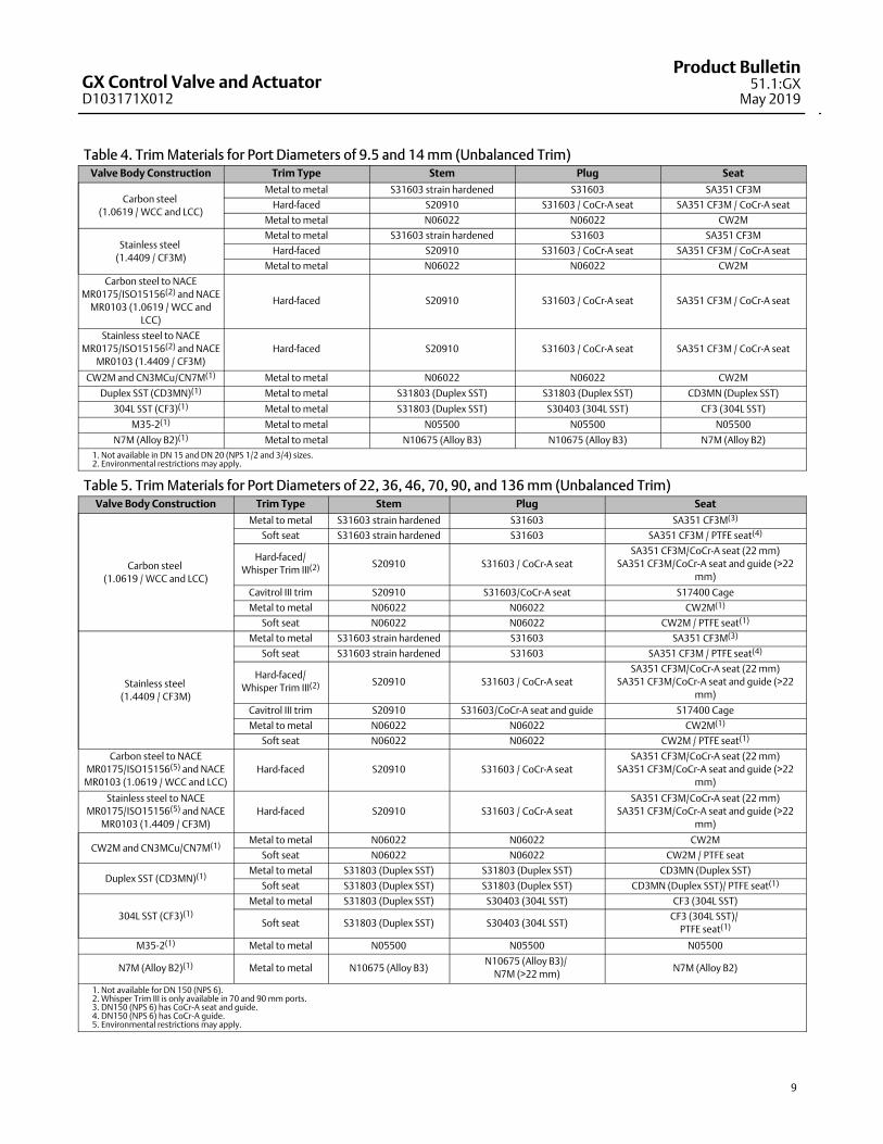
Table 4. Trim Materials for Port Diameters of 9.5 and 14 mm (Unbalanced Trim)Valve Body Construction Trim Type Stem Plug Seat
Carbon steel
(1.0619 / WCC and LCC)
Metal to metal S31603 strain hardened S31603 SA351 CF3M
Hard-faced S20910 S31603 / CoCr-A seat SA351 CF3M / CoCr-A seat
Metal to metal N06022 N06022 CW2M
Stainless steel
(1.4409 / CF3M)
Metal to metal S31603 strain hardened S31603 SA351 CF3M
Hard-faced S20910 S31603 / CoCr-A seat SA351 CF3M / CoCr-A seat
Metal to metal N06022 N06022 CW2M
Carbon steel to NACE
MR0175/ISO15156(2) and NACE
MR0103 (1.0619 / WCC and
LCC)
Hard-faced S20910 S31603 / CoCr-A seat SA351 CF3M / CoCr-A seat
Stainless steel to NACE
MR0175/ISO15156(2) and NACE
MR0103 (1.4409 / CF3M)
Hard-faced S20910 S31603 / CoCr-A seat SA351 CF3M / CoCr-A seat
CW2M and CN3MCu/CN7M(1) Metal to metal N06022 N06022 CW2M
Duplex SST (CD3MN)(1) Metal to metal S31803 (Duplex SST) S31803 (Duplex SST) CD3MN (Duplex SST)
304L SST (CF3)(1) Metal to metal S31803 (Duplex SST) S30403 (304L SST) CF3 (304L SST)
M35-2(1) Metal to metal N05500 N05500 N05500
N7M (Alloy B2)(1) Metal to metal N10675 (Alloy B3) N10675 (Alloy B3) N7M (Alloy B2)
1. Not available in DN 15 and DN 20 (NPS 1/2 and 3/4) sizes.2. Environmental restrictions may apply.
Table 5. Trim Materials for Port Diameters of 22, 36, 46, 70, 90, and 136 mm (Unbalanced Trim)Valve Body Construction Trim Type Stem Plug Seat
Carbon steel
(1.0619 / WCC and LCC)
Metal to metal S31603 strain hardened S31603 SA351 CF3M(3)
Soft seat S31603 strain hardened S31603 SA351 CF3M / PTFE seat(4)
Hard-faced/
Whisper Trim III(2) S20910 S31603 / CoCr-A seat
SA351 CF3M/CoCr-A seat (22 mm)
SA351 CF3M/CoCr-A seat and guide (>22
mm)
Cavitrol III trim S20910 S31603/CoCr-A seat S17400 Cage
Metal to metal N06022 N06022 CW2M(1)
Soft seat N06022 N06022 CW2M / PTFE seat(1)
Stainless steel
(1.4409 / CF3M)
Metal to metal S31603 strain hardened S31603 SA351 CF3M(3)
Soft seat S31603 strain hardened S31603 SA351 CF3M / PTFE seat(4)
Hard-faced/
Whisper Trim III(2) S20910 S31603 / CoCr-A seat
SA351 CF3M/CoCr-A seat (22 mm)
SA351 CF3M/CoCr-A seat and guide (>22
mm)
Cavitrol III trim S20910 S31603/CoCr-A seat and guide S17400 Cage
Metal to metal N06022 N06022 CW2M(1)
Soft seat N06022 N06022 CW2M / PTFE seat(1)
Carbon steel to NACE
MR0175/ISO15156(5) and NACE
MR0103 (1.0619 / WCC and LCC)
Hard-faced S20910 S31603 / CoCr-A seat
SA351 CF3M/CoCr-A seat (22 mm)
SA351 CF3M/CoCr-A seat and guide (>22
mm)
Stainless steel to NACE
MR0175/ISO15156(5) and NACE
MR0103 (1.4409 / CF3M)
Hard-faced S20910 S31603 / CoCr-A seat
SA351 CF3M/CoCr-A seat (22 mm)
SA351 CF3M/CoCr-A seat and guide (>22
mm)
CW2M and CN3MCu/CN7M(1)Metal to metal N06022 N06022 CW2M
Soft seat N06022 N06022 CW2M / PTFE seat
Duplex SST (CD3MN)(1)Metal to metal S31803 (Duplex SST) S31803 (Duplex SST) CD3MN (Duplex SST)
Soft seat S31803 (Duplex SST) S31803 (Duplex SST) CD3MN (Duplex SST)/ PTFE seat(1)
304L SST (CF3)(1)
Metal to metal S31803 (Duplex SST) S30403 (304L SST) CF3 (304L SST)
Soft seat S31803 (Duplex SST) S30403 (304L SST)CF3 (304L SST)/
PTFE seat(1)
M35-2(1) Metal to metal N05500 N05500 N05500
N7M (Alloy B2)(1) Metal to metal N10675 (Alloy B3)N10675 (Alloy B3)/
N7M (>22 mm)N7M (Alloy B2)
1. Not available for DN 150 (NPS 6).2. Whisper Trim III is only available in 70 and 90 mm ports.3. DN150 (NPS 6) has CoCr-A seat and guide.4. DN150 (NPS 6) has CoCr-A guide.5. Environmental restrictions may apply.

GX Control Valve and ActuatorD103171X012
Product Bulletin51.1:GXMay 2019
10
Table 6. Trim Materials for Port Diameters of 70, 90, and 136 mm (Balanced Trim)(3)
Valve Body Construction Trim Type Stem Plug Seat
Carbon steel
(1.0619 / WCC and LCC)(1)
Metal to metal S31603 strain hardened S31603 SA351 CF3M
Hard-faced/
Whisper Trim III(4) S20910S31603 / CoCr-A seat and
guide
SA351 CF3M / CoCr-A seat
and guide
Metal to metal N06022 N06022 CW2M(2)
Stainless steel
(1.4409 / CF3M)
Metal to metal S31603 strain hardened S31603 SA351 CF3M
Hard-faced/Whisper Trim III(4) S20910S31603 / CoCr-A seat and
guide
SA351 CF3M / CoCr-A seat
and guide
Metal to metal N06022 N06022 CW2M(2)
Carbon steel to NACE
MR0175/ISO15156(5) and NACE
MR0103 (1.0619 / WCC and LCC)
Hard-faced S20910 S31603 / CoCr-A seatSA351 CF3M / CoCr-A seat
and guide
Stainless steel to NACE
MR0175/ISO15156(5) and NACE
MR0103 (1.4409 / CF3M)
Hard-faced S20910 S31603 / CoCr-A seatSA351 CF3M / CoCr-A seat
and guide
CW2M and CN3MCu/CN7M(2) Metal to metal N06022 N06022 CW2M
Duplex SST (CD3MN)(2) Metal to metal S31803 (Duplex SST) S31803 (Duplex SST) CD3MN (Duplex SST)
304L SST (CF3)(2) Metal to metal S31803 (Duplex SST) S30403 (304L SST) CF3 (304L SST)
1. The bonnet used in the carbon steel balanced trim construction is made of 1.4409/CF3M stainless steel.2. Not available for DN 150 (NPS 6).3. Balanced trim not available with M35-2 or N7M trim.4. Balanced Whisper Trim III in DN150 (NPS 6) 136 mm port diameter only.5. Environmental restrictions may apply.
Table 7. Fisher GX Availability
VALVE SIZEPORT SIZE STEM DIAMETER TRAVEL
ACTUATOR SIZEmm mm mm
DN15
(NPS 1/2)9.5
10
20 Plain
DN20
(NPS 3/4)
14 20 Plain
9.5 20 Plain
DN25
(NPS 1)
22 20 Plain
14 20 Plain
9.5 20 Plain
DN40
(NPS 1-1/2)
36 20 Plain
22 20 Plain
14 20 Plain
DN50
(NPS 2)
46 20 Plain
36 20 Plain
22 20 Plain
DN80
(NPS 3)
70
14
40 Plain
46 20 Plain
36 20 Plain
DN100
(NPS 4)
90 40 Plain
70 40 Plain
46 20 Plain
DN150
(NPS 6)
13619
60 Plain
90 40 Plain

GX Control Valve and ActuatorD103171X012
Product Bulletin51.1:GX
May 2019
11
Table 8. Allowable Temperature Ranges for Valve Body, Bonnet and Trim(1)
VALVE BODY /BONNET MATERIAL
BONNETSTYLE
ENVIRO-SEALPACKING
GASKET TRIM STYLE
TEMPERATURE
�C �F
Min Max Min Max
1.0619/SA216
WCC Steel
Standard
PTFE or
Graphite ULF
Graphite laminate or
PTFE / N10276Metal to metal; hard-faced; soft seat -29 232 -20 450
Extension Graphite laminate Metal to metal; hard-faced -29 371 -20 700
Bellows
Graphite laminate or
PTFE / N10276Metal to metal; hard-faced; soft seat -29 232 -20 450
Graphite laminate Metal to metal; hard-faced -29 371 -50 700
1.4409/SA351
CF3M SST
StandardGraphite laminate or
PTFE / N10276Metal to metal; hard-faced; soft seat -46 232 -50 450
Extension Graphite laminate Metal to metal; hard-faced -46 371 -50 700
Cryogenic
ExtensionGraphite laminate Metal to metal; hard-faced (2) 371 (2) 700
Bellows
Graphite laminate or
PTFE / N10276Metal to metal; hard-faced; soft seat -46 232 -50 450
Graphite laminate Metal to metal; hard-faced -46 371 -50 700
CW2M
StandardGraphite laminate or
PTFE / N10276Metal to metal; soft seat -46 232 -50 450
BellowsGraphite laminate or
PTFE / N10276Metal to metal; soft seat -46 232 -50 450
LCC
StandardGraphite laminate or
PTFE / N10276Metal to metal; hard-faced; soft seat -46 232 -50 450
Extension Graphite laminate Metal to metal; hard-faced -46 343 -50 650
Bellows
Graphite laminate or
PTFE / N10276Metal to metal; hard-faced; soft seat -46 232 -50 450
Graphite laminate Metal to metal; hard-faced -46 343 -50 650
CN3MCu/CN7M Standard
PTFE
Graphite laminate or
PTFE / N10276Metal to metal; soft seat -46 232 -50 450
304L SST (CF3) StandardGraphite laminate or
PTFE / S30403Metal to metal; soft seat -46 232 -50 450
Duplex SST (CD3MN) StandardGraphite laminate or
PTFE / N10276Metal to metal; soft seat -46 232 -50 450
M35-2 StandardGraphite laminate or
PTFE / N04400Metal to metal -46 232 -50 450
N7M (Alloy B2) StandardGraphite laminate or
PTFE / N10276Metal to metal -46 232 -50 450
1. Back-up ring materials used in Sizes DN 80, 100, and 150 (NPS 3, 4, and 6) with balanced trim may be limited by temperature and application. See table 2.2. Consult your Emerson sales office for minimum temperature limit.

GX Control Valve and ActuatorD103171X012
Product Bulletin51.1:GXMay 2019
12
Figure 9. Material Pressure/Temperature Curves
E1026
E1140
1. N7M is only offered with CL150 and CL300 (not PN10, PN16, PN25, or PN40).
1

GX Control Valve and ActuatorD103171X012
Product Bulletin51.1:GX
May 2019
13
Figure 10. Material Pressure/Temperature Curves
E0901
1
1. CD3MN, CN3MCu/CN7M, and M35-2 are not listed in EN 12516-1. The PN designations are used only to indicate relative pressure-retaining capabilities.
1
1Pressure/Temperature Chart for CN3MCu/CN7M
GX Control Valve and ActuatorD103171X012
Product Bulletin51.1:GXMay 2019
14
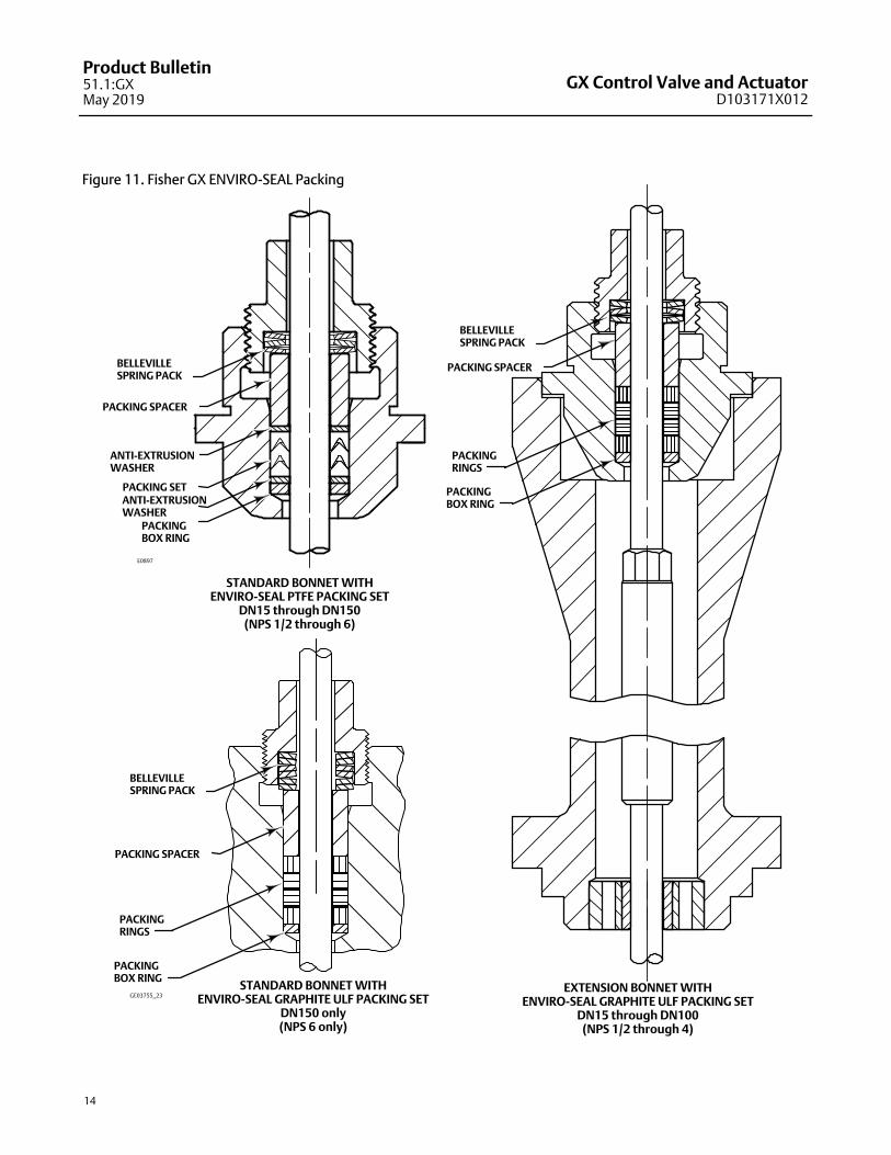
Figure 11. Fisher GX ENVIRO-SEAL Packing
BELLEVILLESPRING PACK
PACKING SPACER
PACKING SETANTI-EXTRUSIONWASHER
PACKINGBOX RING
ANTI-EXTRUSIONWASHER
STANDARD BONNET WITHENVIRO-SEAL PTFE PACKING SET
DN15 through DN150(NPS 1/2 through 6)
EXTENSION BONNET WITHENVIRO-SEAL GRAPHITE ULF PACKING SET
DN15 through DN100(NPS 1/2 through 4)
BELLEVILLESPRING PACK
PACKING SPACER
PACKINGBOX RING
PACKINGRINGS
E0897
STANDARD BONNET WITHENVIRO-SEAL GRAPHITE ULF PACKING SET
DN150 only(NPS 6 only)
BELLEVILLESPRING PACK
PACKING SPACER
PACKINGRINGS
PACKINGBOX RING
GE03755_23

GX Control Valve and ActuatorD103171X012
Product Bulletin51.1:GX
May 2019
15
Figure 12. GX Cavitrol III Trim
X0112
GX Cavitrol III for DN25 (NPS 1) through DN50 (NPS 2)Cavitrol III trim lowers hydrodynamic noise andreduces vibration by utilizing proprietary drilled holeshape and spacing to shift the frequency and isolatethe cavitation in order to prevent damage. Cavitrol III1stage technology is used without altering theintegral GX bonnet design.
Features
� Max deltaP of 400 psid
� Flow down
� Class V shutoff – standard
Available Sizes
� NPS 1, 225 Actuator, 20mm travel
� NPS 1-1/2, 750 Actuator, 20mm travel
� NPS 2, 750 Actuator, 20mm travel
Requirements
� Minimum 4 bar supply pressure
� Only available with standard bonnet
Table 9. Materials of Construction for Cavitrol III TrimPart Material
Stem S20910
Plug S31603 / CoCr‐A Seat and Guide
Seat Ring / Cage S17400
Figure 13. GX Whisper Trim III
X0336
GX Whisper Trim III forDN80 (NPS 3) throughDN150 (NPS 6)Whisper Trim III A1 lowers aerodynamic valve noise byutilizing multiple orifices of special shape, size, andspacing. These orifices break up turbulentcompressible fluid streams and shift the acousticenergy to a higher frequency range. The result is about20 dBA noise attenuation.
Features
� Flow up
� Class IV shutoff
Available Sizes
� NPS 3, 750 Actuator, 40mm travel
� NPS 4, 750 Actuator, 40mm travel
� NPS 6, 1200 Actuator, 60mm travel
Table 10. Materials of Construction for Whisper Trim III(1)
Part Material
Stem S20910
Plug S31603 / CoCr‐A Seat
Seat Ring S31603 / CoCr‐A Seat and Guide
Cage(1) CF3M
1. NPS 6 uses a separate cage, not integral to the plug stem.
Allowable temperature ranges are shown in table 8.
GX Control Valve and ActuatorD103171X012
Product Bulletin51.1:GXMay 2019
16
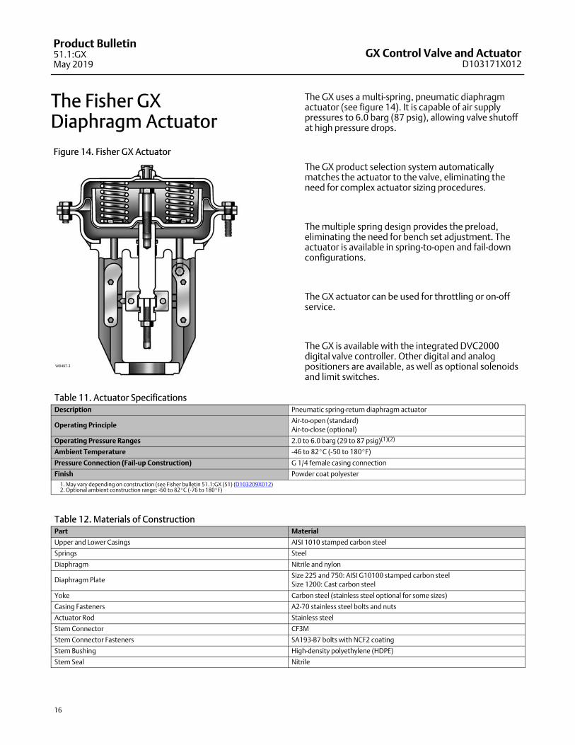
The Fisher GX Diaphragm Actuator
Figure 14. Fisher GX Actuator
W8487-3
The GX uses a multi-spring, pneumatic diaphragmactuator (see figure 14). It is capable of air supplypressures to 6.0 barg (87 psig), allowing valve shutoffat high pressure drops.
The GX product selection system automaticallymatches the actuator to the valve, eliminating theneed for complex actuator sizing procedures.
The multiple spring design provides the preload,eliminating the need for bench set adjustment. Theactuator is available in spring-to-open and fail-downconfigurations.
The GX actuator can be used for throttling or on-offservice.
The GX is available with the integrated DVC2000digital valve controller. Other digital and analogpositioners are available, as well as optional solenoidsand limit switches.
Table 11. Actuator SpecificationsDescription Pneumatic spring-return diaphragm actuator
Operating PrincipleAir-to-open (standard)
Air-to-close (optional)
Operating Pressure Ranges 2.0 to 6.0 barg (29 to 87 psig)(1)(2)
Ambient Temperature -46 to 82�C (-50 to 180�F)
Pressure Connection (Fail-up Construction) G 1/4 female casing connection
Finish Powder coat polyester
1. May vary depending on construction (see Fisher bulletin 51.1:GX (S1) (D103209X012)2. Optional ambient construction range: -60 to 82�C (-76 to 180�F)
Table 12. Materials of ConstructionPart Material
Upper and Lower Casings AISI 1010 stamped carbon steel
Springs Steel
Diaphragm Nitrile and nylon
Diaphragm PlateSize 225 and 750: AISI G10100 stamped carbon steel
Size 1200: Cast carbon steel
Yoke Carbon steel (stainless steel optional for some sizes)
Casing Fasteners A2-70 stainless steel bolts and nuts
Actuator Rod Stainless steel
Stem Connector CF3M
Stem Connector Fasteners SA193-B7 bolts with NCF2 coating
Stem Bushing High-density polyethylene (HDPE)
Stem Seal Nitrile

GX Control Valve and ActuatorD103171X012
Product Bulletin51.1:GX
May 2019
17
Actuator Selection
With the GX, actuator selection has never been easier.Once the valve size and port diameter have beendetermined, the actuator is automatically selected. Nospring selection or bench set calculations are required.
The majority of GX constructions (both fail-down andfail-up) are rated to a full pressure class shutoffcapability of 51.7 bar (750 psi) for a 4 to 6 bar (58 to 87psig) actuator air supply. Refer to Fisher GX BulletinSupplement 51.1:GX (S1) (D103209X012) foradditional information.
The GX actuator has been optimized to allow forvarying ranges of supply pressure. See table 13.
Table 13. Fisher GX Actuator Supply Pressure Ranges
SUPPLY PRESSURERANGE
Bar Psig
Standard 4.0 to 6.0 58 to 87
Optional 3.0 to 4.0 44 to 58
Optional 2.0 to 3.0 29 to 44
GX ISO 5210 ElectricActuator MountingElectric actuator mounting is available for anymanufacturing models that comply with ISO 5210,Flange type F7. The mounting offering includes a GXyoke, actuator rod adaptor, spacer, and bolting.
CAUTION
The up travel stop must be set in the electric actuator inorder to prevent damage to the valve trim.
Thrust limitations apply when sizing electric actuators(see table 14).
A mounting offering can be engineered if not alreadyavailable for a selected actuator. Electric actuatormounting is not available for DN150, NPS 6 GX valves.For additional information, contact your Emerson salesoffice.
Bellows Extension BonnetThe GX bellows extension bonnet provides reliable andtight stem sealing for those applications whereemissions escaping to the environment cannot betolerated (see figure 15). The GX bellows is available inSST (1.4571 / 316Ti) or N10276 and covers a full rangeof valve sizes from DN 15 through DN 100 (NPS 1/2through 4) (see tables 15 and 16).
The GX bellows system has been designed for 100,000full-travel cycles at maximum allowable pressure andambient temperature (20�C [68�F]).
The mechanically-formed metal bellows provides highoperating reliability and extended cycle life (see tables17, 18, and 19 for details).
The GX bellows design incorporates a rugged double-or triple-wall construction for added security. Eachbellows is helium tested before leaving the factory.
The GX bellows bonnet comes standard with anENVIRO-SEAL live-loaded, PTFE packing system as asecurity backup. A connection is provided above thebellows to allow purging or monitoring the integrity ofthe replaceable bellows.
Table 14. Fisher GX Maximum Allowable Thrust for use with ISO 5210 Electric Actuators
VALVE SIZESTEM DIAMETER TRAVEL
BONNET STYLESTEM MATERIAL
STRENGTH
MAXIMUM THRUST
mm mm N lbf
DN15-DN50
(NPS 1/2 to 2)10 20
PlainHigh(1) 17000 3820
Low(2) 7600 1710
Bellows/ExtensionHigh 11400 2560
Low 6700 1500
DN80-DN100
(NPS 3 to 4)14 20, 40
PlainHigh 20000 4500
Low 20000 4500
Bellows/ExtensionHigh 20000 4500
Low 14500 3260
1. High strength stem materials consist of S20910, N05500, S316032. Low strength stem materials consist of S31803, N10665, N06022

GX Control Valve and ActuatorD103171X012
Product Bulletin51.1:GXMay 2019
18
Figure 15. Fisher GX Bellows Bonnet and Selection Process
W8958-1
PACKINGFOLLOWER
BONNET
ENVIRO-SEALPTFE PACKING
BODY/BONNETGASKET
PURGE / MONITORINGCONNECTION
BELLOWS NUT
BELLOWSGASKET
BELLOWS/STEMASSEMBLY
EXTENSIONBONNET
BUSHING
VALVE PLUG
Step 1
Size and select the GX control valve that is appropriatefor the application. This will identify the:
� Valve body size� Actuator size� Orifice size�Trim style (balanced or unbalanced)� Valve body material
Step 4Using bulletin 51.1:GX(S1), verify the application pressuredrop does not exceed the actuator capability.
Step 2
Confirm bellows availability from table 15.
Step 3
Using table 16, select the bellows material combinationthat is appropriate for the application. Using thetemperature limits shown in table 8, confirm theselected construction is appropriate for the applicationtemperatures.
Step 5
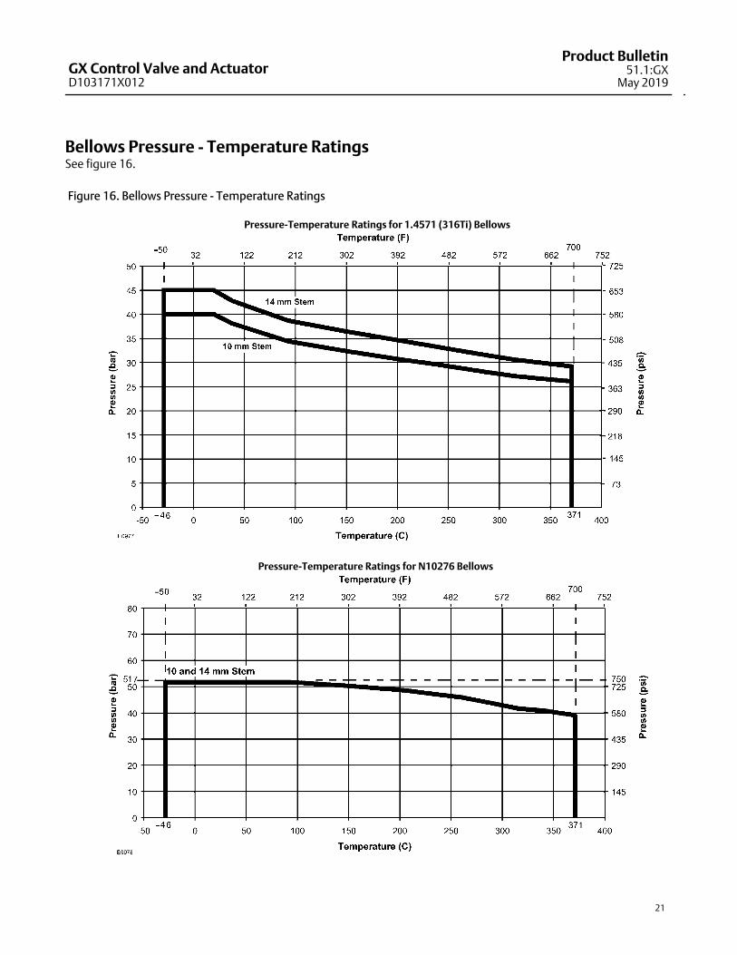
Using figure 16, check to ensure the maximum processpressure and temperature do not exceed the pressure-temperature rating of the selected bellows.
Bellows Selection ProcessFollow this process to assist in selecting the
appropriate bellows for the application:

GX Control Valve and ActuatorD103171X012
Product Bulletin51.1:GX
May 2019
19
Table 15. Fisher GX Constructions with Bellows AvailabilityVALVE BODY SIZES PORT SIZE (mm) ACTUATOR SIZES PLUG TRAVEL TRIM STYLE
DN15-50
(NPS 1/2 to 2)4.8 to 46 225 and 750 20 mm Unbalanced
DN80
(NPS 3)
36 to 46 750 20 mm Unbalanced
70 750 20 mm Balanced
DN100
(NPS 4)
46 750 20 mm Unbalanced
90 750 20 mm Balanced
Table 16. Bellows Materials of Construction
Valve Body /Bonnet
BellowsBellows
StemExtension
Trim Materials
BoltingENVIRO-SEAL
PackingGaskets Lower Bushing
MonitoringConnection
PlugPlug(1) Stem
Material
Carbon Steel
(1.0619/WCC
and LCC)
SST
(1.4571/316Ti)S31603
S31603 or
CF3MS31603
SA193-B7
with NCF2
coating
Live-loaded
PTFE
Graphite
laminate
S31600 with
R31233 insertS31600
N10276 S31603S31603 or
CF3MS31603
SA193-B7
with NCF2
coating
Live-loaded
PTFE
Graphite
laminate
S31600 with
R31233 insertS31600
N10276 N06022N06022 or
CW2MN06022 S20910
Live-loaded
PTFE
Graphite
laminate
N10276 with
R31233 insertN10276
Stainless Steel
(1.4409/CF3M)
SST
(1.4571/316Ti)S31603
S31603 or
CF3MS31603 S20910
Live-loaded
PTFE
Graphite
laminate
S31600 with
R31233 insertS31600
N10276 S31603S31603 or
CF3MS31603 S20910
Live-loaded
PTFE
Graphite
laminate
S31600 with
R31233 insertS31600
N10276 N06022N06022 or
CW2MN06022 S20910
Live-loaded
PTFE
Graphite
laminate
N10276 with
R31233 insertN10276
CW2M N10276 N06022N06022 or
CW2MN06022 S20910
Live-loaded
PTFE
Graphite
laminate
N10276 with
R31233 insertN10276
1. Plug material for the 4.8 mm port is R31233.
For bellows height dimensions, see table 21.

GX Control Valve and ActuatorD103171X012
Product Bulletin51.1:GXMay 2019
20
+Cycle LifeBellows service life is affected by several factors, including process pressure, temperature, and plug travel. Tables 17,18, 19, and 20 provide estimates of cycle life for several cases.
Table 17. Estimated Bellows Cycle Life at 10.3 bar (150 psig) and 20�C (68�F)
VALVE SIZE STEM SIZE BELLOWS MATERIAL PLYS BELLOWS PRESSURE
PROCESSTEMPERATURE ESTIMATED CYCLE LIFE
(50% Stroke [25-75% travel])�C �F
DN15-50
(NPS 1/2 to 2)10mm
1.4571 (316Ti) 210.3 bar
(150 psig)20 68 1,040,000
N10276 310.3 bar
(150 psig)20 68 910,000
DN80-100
(NPS 3 to 4)14mm
1.4571 (316Ti) 210.3 bar
(150 psig)20 68 1,020,000
N10276 210.3 bar
(150 psig)20 68 980,000
Table 18. Estimated Bellows Cycle Life at Bellows Maximum Allowable Pressure and 20�C (68�F)
VALVE SIZE STEM SIZE BELLOWS MATERIAL PLYS
MAXIMUMALLOWABLE
BELLOWSPRESSURE(1)
PROCESSTEMPERATURE ESTIMATED CYCLE LIFE
(50% Stroke [25-75% travel])�C �F
DN15-50
(NPS 1/2 to 2)10mm
1.4571 (316Ti) 240 bar
(580 psig)20 68 830,000
N10276 351.7 bar
(750 psig)20 68 800,000
DN80-100
(NPS 3 to 4)14mm
1.4571 (316Ti) 245 bar
(650 psig)20 68 800,000
N10276 251.7 bar
(750 psig)20 68 810,000
1. Valve maximum allowable pressure drop may be limited by size and material. See Fisher bulletin 51.1:GX (S1) (D103209X012) for additional information.
Table 19. Estimated Bellows Cycle Life at Bellows Maximum Allowable Pressure and 232�C (450�F)
VALVE SIZE STEM SIZE BELLOWS MATERIAL PLYS
MAXIMUMALLOWABLE
BELLOWSPRESSURE(1)
PROCESSTEMPERATURE ESTIMATED CYCLE LIFE
(50% Stroke [25-75% travel])�C �F
DN15-50
(NPS 1/2 to 2)10mm
1.4571 (316Ti) 229.8 bar
(430 psig)232 450 410,000
N10276 347.2 bar
(685 psig)232 450 560,000
DN80-100
(NPS 3 to 4)14mm
1.4571 (316Ti) 233.5 bar
(485 psig)232 450 390,000
N10276 247.2 bar
(685 psig)232 450 550,000
1. Valve maximum allowable pressure drop may be limited by size and material. See Fisher bulletin 51.1:GX (S1) (D103209X012) for additional information.
Table 20. Estimated Bellows Cycle Life at Bellows Maximum Allowable Pressure and 371�C (700�F)
VALVE SIZE STEM SIZE BELLOWS MATERIAL PLYSMAXIMUM
ALLOWABLEBELLOWS PRESSURE
PROCESSTEMPERATURE ESTIMATED CYCLE LIFE
(50% Stroke [25-75% travel])�C �F
DN15-50
(NPS 1/2 to 2)10mm
1.4571 (316Ti) 226.1 bar
(380 psig)371 700 250,000
N10276 339.3 bar
(570 psig)371 700 430,000
DN80-100
(NPS 3 to 4)14mm
1.4571 (316Ti) 229.3 bar
(425 psig)371 700 240,000
N10276 239.3 bar
(570 psig)371 700 430,000
GX Control Valve and ActuatorD103171X012
Product Bulletin51.1:GX
May 2019
21
Bellows Pressure - Temperature RatingsSee figure 16.
Figure 16. Bellows Pressure - Temperature Ratings
Pressure-Temperature Ratings for 1.4571 (316Ti) Bellows
Pressure-Temperature Ratings for N10276 Bellows

GX Control Valve and ActuatorD103171X012
Product Bulletin51.1:GXMay 2019
22
Valve-Actuator Dimensions and WeightsSee figure 17 and table 21.
Figure 17. Fisher GX Dimensions (also see table 21)
E
D
AR
A/2
A
F
C
W8486-3
GX STEM-GUIDED CONSTRUCTION (DN25 / NPS 1)
Table 21. Fisher GX Dimensions and Weights
VALVESIZE
PORTDIA ACTUATOR
SIZE
A C D
ECasing
Dia
F (AR)RemovalHeight(3)
TOTAL WEIGHT
PN10/ 16& PN25/
40
CL150 CL300Standard
Bonnet
Extendedor
BellowsBonnet
ActuatorHeight
(StandardBonnet)
ActuatorHeight
(Extendedor Bellows
Bonnet)
WithStandard
Bonnet
WithExtended
orBellowsBonnet
mm mm mm mm mm mm mm mm mm mm kg kg
DN 15/
NPS 1/24.8, 9.5 225 130 184 190 66 304 313 313 270 115 21 25
DN 20/
NPS 3/4
4.8,
9.5, 14225 150 184 194 66 304 313 313 270 115 22 26
DN 25/
NPS 1
4.8,
9.5, 14,
22
225 160 184 197 58 296 313 313 270 115 22 26
DN 40/
NPS
1-1/2
14, 22,
36225 200 222 235 62 300 313 313 270 115 25 29
36 750 200 222 235 62 300 342 342 430 115 52 56
DN 50/
NPS 2
22, 36,
46225 230 254 267 68 306 313 313 270 115 29 33
36, 46 750 230 254 267 68 306 342 342 430 115 56 60
DN 80/
NPS 3
36, 46 750 310 298 318 105 373 375 375 430 125 79 88
70(1)
70
750
750
310
310
298
298
318
318
105
105
373(4)
373
375
395
375
395
430
430
125
125
81
83
90
92
DN 100/
NPS 4
46
70
750
750
350
350
352
352
368
368
121
121
393
393
379
399
375
395
430
430
130
130
98
101
109
111
90(2)
90(1) 750 350 352 368 121 393(4) 379 375 430 130 105 115
90 750 350 352 368 121 393 399 395 430 130 101 111
DN 150/
NPS 6
136
136(1)
136(5)
1200
1200
1200
480
480
480
451
451
451
473
473
473
189
200
230
- - -- - -- - -
559
559
589
- - -- - -- - -
566
566
566
224
210
240
235
247
247
- - -- - -- - -
1. Balanced trim design.2. Balanced trim with reduced-capacity plug.3. Clearance required for removing actuator from installed valve body.4. Bellows bonnets are available for these constructions. However, extension bonnets are not available with balanced trim due to temperature limitations of the trim seals.5. Severe service.
GX Control Valve and ActuatorD103171X012
Product Bulletin51.1:GX
May 2019
23
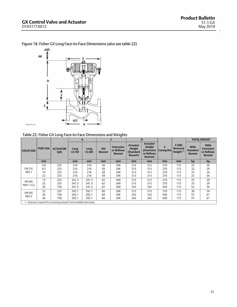
Figure 18. Fisher GX Long Face-to-Face Dimensions (also see table 22)
E
D
AR
A/2
A
F
C
GE03755_4_3
Table 22. Fisher GX Long Face-to-Face Dimensions and Weights
VALVE SIZEPORT DIA ACTUATOR
SIZE
A C D
ECasing Dia
F (AR)Removal
Height(1)
TOTAL WEIGHT
LongCL150
LongCL300
StdBonnet
Extensionor Bellows
Bonnet
ActuatorHeight
(StandardBonnet)
ActuatorHeight
(Extensionor Bellows
Bonnet)
WithStandard
Bonnet
WithExtensionor Bellows
Bonnet
mm mm mm mm mm mm mm mm mm kg kg
DN 25/
NPS 1
4.8
9.5
14
22
225
225
225
225
216
216
216
216
216
216
216
216
58
58
58
58
296
296
296
296
313
313
313
313
313
313
313
313
270
270
270
270
115
115
115
115
22
22
22
22
26
26
26
26
DN 40/
NPS 1‐1/2
14
22
36
225
225
750
241.3
241.3
241.3
241.3
241.3
241.3
62
62
62
300
300
300
313
313
342
313
313
342
270
270
430
115
115
115
25
25
52
29
29
56
DN 50/
NPS 2
22
36
46
225
750
750
292.1
292.1
292.1
292.1
292.1
292.1
68
68
68
306
306
306
313
342
342
313
342
342
270
430
430
115
115
115
30
57
57
34
61
61
1. Clearance required for removing actuator from installed valve body.

GX Control Valve and ActuatorD103171X012
Product Bulletin51.1:GXMay 2019
24
Figure 19. Fisher GX Electric Actuator Mounting Dimensions (also see table 23)
H
G
GE54731-2
GX ELECTRIC ACTUATOR MOUNTING
K
Table 23. Fisher GX Electric Actuator Mounting Dimensions and Weights
VALVE SIZEPORT DIAMETER G H K
GX ELECTRIC ACTUATOR MOUNTINGWEIGHT
With StandardBonnet
With Extension orBellow Bonnet
mm mm mm mm kg kg
DN 15/ NPS 1/2 4.8, 9.5 202 170 92 12 16
DN 20/ NPS 3/4 4.8, 9.5, 14 202 170 92 13 17
DN 25/ NPS 1 4.8, 9.5, 14, 22 202 170 92 13 17
DN 40/ NPS 1-1/214, 22, 36
202 170 9216 20
36 15 19
DN 50/ NPS 222, 36, 46
202 170 9220 24
36, 46 19 23
DN 80/ NPS 3
36, 46
222 170 92
42 51
70(1)
70
44
43
53
52
DN 100/ NPS 4
46
70
226 170 92
61
61
72
71
90(2)
90(1) 65 75
90 64 74
1. Balanced trim design.2. Balanced trim with reduced-capacity plug.3. Severe service.

GX Control Valve and ActuatorD103171X012
Product Bulletin51.1:GX
May 2019
25
Table 24. Positioner Selection Guidelines
Type Digital I/P(1) I/P(2) P/P(3) IntrinsicSafety(4)
Flameproof /Explosionproof(4) Non- Incendive(4)
DVC2000 X X X
DVC6200 X X X X
3661 X X X
3660 X
1. Digital I/P - microprocessor based electro-pneumatic with HART communication.2. I/P - electro-pneumatic3. P/P - pneumatic4. Refer to Fisher bulletin 9.2:001 (D103222X012) for instrument hazardous area classification details.
Fisher GX ActuatorAccessoriesThe GX is available with a variety of pneumatic (P/P),electro-pneumatic (I/P), and digital valve positioners,as well as limit switches and solenoids. Table 24provides the basic features of the positioners offeredwith the GX actuator.
The Fisher FIELDVUEDVC2000 Digital ValveControllerThe DVC2000 digital valve controller (figure 20) issimple to use, compact, and designed for the GXcontrol valve. It converts a 4-20mA input signal into apneumatic output signal, which feeds the control valveactuator. Instrument setup is performed with apushbutton and LCD interface. This interface isprotected from the environment within an IP66enclosure. Multiple languages are supported with thelocal interface including German, French, Italian,Spanish, Chinese, Japanese, Portuguese, Russian,Polish, Czech, Arabic, and English. Additionally, HART�communication is supported over the 4-20mA loopwiring.
The DVC2000 is designed to be integrally mounted tothe GX actuator, avoiding the need for mountingbrackets. The DVC2000 mounts directly to an interfacepad on the actuator yoke leg with a secure 3-pointmounting. An internal passage inside the yoke legtransmits the pneumatic signal to the actuator casing,eliminating the need for external tubing (in theair-to-open configuration).
Figure 20. Fisher FIELDVUE DVC2000 Digital Valve Controller
W8755
The high-performance linkage-less position feedbacksystem eliminates physical contact between the valvestem and the digital valve controller or instrument.There are no wearing parts so cycle life is maximized.Additionally, the elimination of levers and linkagesreduces the number of mounting parts and themounting complexity. Digital valve controller orinstrument replacement and maintenance is simplifiedbecause the feedback parts stay connected to theactuator.
The DVC2000 is available with an optional modulewhich includes two (2) integral limit switches and astem position transmitter. The limit switches areconfigurable for open and closed valve indication. Theposition transmitter provides a 4-20mA signal for valveposition feedback verification. As an integralcomponent to the instrument, this option moduleavoids the need for difficult-to-mount externalswitches and transmitters.
Designed to meet intrinsic safety and non-incendiverequirements, this instrument delivers scalablefunctionality and high performance in a small package.

GX Control Valve and ActuatorD103171X012
Product Bulletin51.1:GXMay 2019
26
Optional Positioners and Instruments
Fisher FIELDVUE DVC6200 Digital Valve Controller
The DVC6200 digital valve controller is acommunicating, microprocessor-basedcurrent-to-pneumatic instrument. Using HART orFOUNDATION� fieldbus communication protocol,access to critical instrument, valve, and processconditions is provided. When used with ValveLink�software, valve diagnostic tests can be run while thevalve is in service to advise you of the performance ofthe entire control valve assembly. Designed to meet abroad range of hazardous area classifications, thisinstrument offers maximum functionality to improveyour process performance. (See figure 21 and table24.)
Fisher 3660 and 3661 Valve Positioners
The 3660 pneumatic and 3661 electro-pneumaticpositioners are rugged, accurate, and feature lowsteady-state air consumption. Designed to meetintrinsic safety requirements, these positioners offersimple functionality in a small package. (See figure 22 and table 24.)
Figure 21. Fisher FIELDVUE DVC6200 Digital Valve Controller
W9713
Figure 22. Fisher GX Valve with 3660 or 3661 Positioner, NAMUR Mounting (IEC 60534-6-1)
W8590

GX Control Valve and ActuatorD103171X012
Product Bulletin51.1:GX
May 2019
27
Manual HandwheelsThe GX is available with an optional, side-mountedmanual handwheel (see figure 23). These handwheelsprovide a robust method of manually operating thevalve in an emergency or upon loss of instrument air.
The GX handwheel will stroke the valve up to 20mmtravel, and is available on the size 225 and 750
actuators. Dimensions are provided in figure 24 andtable 25.
When mounted to a fail-up actuator, rotating thehandwheel clockwise moves the stem downward.When mounted to a fail-down actuator, turning thehandwheel in the clockwise direction causes the stemto move upward. Disengagement of the handwheel toallow automatic operation is accomplished by turningthe handwheel in the counter-clockwise direction.
Figure 23. Fisher GX Control Valve and Actuator System with Manual Handwheel
W9025

GX Control Valve and ActuatorD103171X012
Product Bulletin51.1:GXMay 2019
28
Figure 24. Fisher GX with Handwheel Dimensions (also see table 25)
E0975
A1
A2
A1A2
C1
C2
� B
� B
Table 25. Fisher GX with Handwheel Dimensions and WeightsVALVE SIZE
ACTUATORSIZE
VALVETRAVEL
HANDWHEELWEIGHT
A1 A2 B C1(1) C2(2)
ENASME
NPS mm kg mm mm mm mm mm
DN 15 1/2 225 20 5.6 215 242 223 159 60
DN 20 3/4 225 20 5.6 215 242 223 159 60
DN 25 1 225 20 5.6 215 242 223 159 60
DN 40 1-1/2225
750
20
20
5.6
12.2
215
293
242
317
223
356
159
159
60
60
DN 50 2225
750
20
20
5.6
12.2
215
293
242
317
223
356
159
159
60
60
DN 80 3 750 20 12.2 293 317 356 169 70
DN 100 4 750 20 12.2 293 317 356 173 74
DN 150 6 1200 Contact your Emerson sales office for information.
1. C1 is fail-down.2. C2 is fail-up.
Emerson Automation Solutions Marshalltown, Iowa 50158 USASorocaba, 18087 BrazilCernay, 68700 FranceDubai, United Arab EmiratesSingapore 128461 Singapore
www.Fisher.com
The contents of this publication are presented for informational purposes only, and while every effort has been made to ensure their accuracy, they are notto be construed as warranties or guarantees, express or implied, regarding the products or services described herein or their use or applicability. All sales aregoverned by our terms and conditions, which are available upon request. We reserve the right to modify or improve the designs or specifications of suchproducts at any time without notice.
� 2003, 2019 Fisher Controls International LLC. All rights reserved.
Fisher, FIELDVUE, ENVIRO-SEAL, Cavitrol, ValveLink, and Whisper Trim are marks owned by one of the companies in the Emerson Automation Solutionsbusiness unit of Emerson Electric Co. Emerson Automation Solutions, Emerson, and the Emerson logo are trademarks and service marks of Emerson ElectricCo. All other marks are the property of their respective owners.
Neither Emerson, Emerson Automation Solutions, nor any of their affiliated entities assumes responsibility for the selection, use or maintenanceof any product. Responsibility for proper selection, use, and maintenance of any product remains solely with the purchaser and end user.