fisher notchflo dst control valve - emerson · figure 1. fisher notchflo dst control valve w9050...
TRANSCRIPT

www.Fisher.com
Fisher™ NotchFlo™ DST Control Valve
ContentsIntroduction 1. . . . . . . . . . . . . . . . . . . . . . . . . . . . . . . . .
Scope of Manual 1. . . . . . . . . . . . . . . . . . . . . . . . . . . . .Description 1. . . . . . . . . . . . . . . . . . . . . . . . . . . . . . . . .Specifications 3. . . . . . . . . . . . . . . . . . . . . . . . . . . . . . .Educational Services 4. . . . . . . . . . . . . . . . . . . . . . . . .
Installation 4. . . . . . . . . . . . . . . . . . . . . . . . . . . . . . . . . .Maintenance 5. . . . . . . . . . . . . . . . . . . . . . . . . . . . . . . . .
Packing Maintenance 7. . . . . . . . . . . . . . . . . . . . . . . . .Adding Packing Rings 9. . . . . . . . . . . . . . . . . . . . .Replacing Packing 9. . . . . . . . . . . . . . . . . . . . . . . .
Trim Removal 12. . . . . . . . . . . . . . . . . . . . . . . . . . . . . .Valve Plug Maintenance 13. . . . . . . . . . . . . . . . . . . . .Lapping Seats 13. . . . . . . . . . . . . . . . . . . . . . . . . . . . . .Trim Replacement 14. . . . . . . . . . . . . . . . . . . . . . . . . .
Parts Ordering 16. . . . . . . . . . . . . . . . . . . . . . . . . . . . . . .Parts Kits 16. . . . . . . . . . . . . . . . . . . . . . . . . . . . . . . . . . .Gasket Kits 18. . . . . . . . . . . . . . . . . . . . . . . . . . . . . . . . .Parts List 20. . . . . . . . . . . . . . . . . . . . . . . . . . . . . . . . . . .
Figure 1. Fisher NotchFlo DST Control Valve
W9050
Introduction
Scope of ManualThis instruction manual includes installation, maintenance, and parts information for the Fisher NotchFlo DST controlvalve. Refer to separate manuals for instructions covering the actuator, positioner, and accessories.
Do not install, operate, or maintain NotchFlo DST valves without being fully trained and qualified in valve, actuator,and accessory installation, operation, and maintenance. To avoid personal injury or property damage, it is importantto carefully read, understand, and follow all the contents of this manual, including all safety cautions and warnings. Ifyou have any questions about these instructions, contact your Emerson sales office before proceeding.
DescriptionThe NotchFlo DST globe (figure 1) and angle valves have metal seats, cage guiding, quick change trim, andpush‐down‐to‐close valve plug action. All available valve sizes and pressure ratings use balanced valve plugs with theexception of CL900 and CL1500 (NPS 1 and 1‐1/2 valves) which use an unbalanced valve plug. To provide a sealbetween the cage and a balanced valve plug, the balanced valve plugs use a pressure‐assisted spring‐loaded seal ring.
A properly sized NotchFlo DST valve with 3‐, 4‐, or 6‐stage dirty service anti‐cavitation trim (figure 2) offers excellentcontrol of high pressure drop liquids with entrained solids, while avoiding the damaging effects of cavitation anderosive solids.
Instruction ManualD103211X012
NotchFlo DST ValveOctober 2018

Instruction ManualD103211X012
NotchFlo DST ValveOctober 2018
2
Table 1. Specifications
Available Valves
CL600 3‐Stage: Level C onlyCL900 and CL1500 � NPS 4, 4‐Stage: Levels A, B, andC(1)
CL1500 � NPS 6, 4‐Stage: Level C onlyCL1500 6‐Stage: Level C onlyCL2500 6‐Stage: Level C only
End Connection Styles and Ratings(2)
Flanged: Consistent with CL600, 900, 1500, and 2500per ASME B16.34
Socket Welding: Consistent with CL600, 900, and1500 per ASME B16.34
Buttwelding: Consistent with CL600, 900, 1500, and2500 per ASME B16.34
Also see table 2
Shutoff Classification
Class V: [5x10-12m3/sec/bar/mm of port diameter(0.0005 mL/min/psid/in) of water at service pressuredrop] per ANSI/FCI 70‐2 and IEC 60534‐4
Flow Characteristic
Linear
Flow Direction
Flow up
Approximate Weights
See table 2
1. Levels A, B, and C provide for varied pressure drops and capacity.2. The pressure/temperature limits in this manual and any applicable standard or code limitation for valve should not be exceeded.
Figure 2. Fisher NotchFlo DST Trim
W8538-1
NotchFlo DST control valves utilize a high resistance, multi‐stage, axial flow path (or passage) where fluid flow isparallel to the axis of the plug and cage.
Pressure reduction occurs throughout the length of the plug; thus individual stages aren't exposed to the full pressuredifferential. Therefore, trim life is enhanced.
NotchFlo DST trim utilizes a series of notched flow restrictions and expansions to control the pressure drop of the fluid.The amount of pressure drop per stage is controlled to prevent cavitation problems and minimize erosion issues.
Flow passage configuration provided by the multi‐stage plug and cage design make the NotchFlo DST valveswell‐suited for applications involving fluids with entrained particles. This is a potentially serious problem for otheranti‐cavitation valve designs which are subject to clogged flow passages.

Instruction ManualD103211X012
NotchFlo DST ValveOctober 2018
3
Design of the trim allows for high rangeability.
SpecificationsSpecifications for NotchFlo DST valves are shown in table 1.
Table 2. Approximate Weights (Valve and Bonnet Assemblies)
VALVE DESIGNVALVE SIZE,
NPSPRESSURE
RATING
KILOGRAMS POUNDS
FlangedSocket Weld(1),
Butt Weld,Screwed(2)
FlangedSocket Weld(1),
Butt Weld,Screwed(2)
3-Stage Globe Valves
1
CL600
20 15 45 35
2 40 30 90 70
3 70 50 155 110
4 120 80 265 175
6 275 230 610 510
8 510 445 1130 980
4-Stage Globe Valves
1
CL900 andCL1500
58 42 128 93
1-1/2 75 48 165 106
2 95 85 210 185
3 185 140 405 310
4 340 280 750 620
3-Stage Angle Valves
1
CL600
20 - - - 44 - - -
2 42 - - - 93 - - -
3 86 - - - 190 - - -
4 140 - - - 315 - - -
6 300 - - - 660 - - -
8 605 - - - 1340 - - -
4-Stage Angle Valves
1
CL900 andCL1500
50 40 110 90
1-1/2 55 45 120 95
2 95 95 210 210
3 185 - - - 405 - - -
4 285 - - - 625 - - -
6 560 - - - 1230 - - -
8 1260 - - - 2770 - - -
4-Stage Cast Angle Valves
1
CL900 andCL1500
40 32 88 71
1-1/2 43 35 95 77
2 75 57 165 126
3 148 118 326 260
4 243 200 536 441
6 523 443 1153 977
8 1062 920 2342 2029
6-Stage Angle Valves
1
CL2500
64 67 140 148
2 180 170 405 375
3 500 473 1110 1043
4 465 433 1025 955
6 1060 1030 2330 2271
6-Stage Globe Valves
1
CL1500
47 43 103 94
2 98 84 217 186
3 354 307 781 677
4 406 386 896 852
6 975 866 2149 1909
1. SWE available on NPS 1, 1-1/2, and 2 only.2. Screwed end available on NPS 1 and 2 CL600 only.

Instruction ManualD103211X012
NotchFlo DST ValveOctober 2018
4
Educational ServicesFor information on available courses for Fisher NotchFlo DST valves, as well as a variety of other products, contact:
Emerson Automation SolutionsEducational Services - RegistrationPhone: 1-641-754-3771 or 1-800-338-8158E-mail: [email protected]/fishervalvetraining
Installation
WARNING
Always wear protective gloves, clothing, and eyewear when performing any installation operations to avoid personalinjury.
Personal injury or property damage caused by sudden release of pressure may result if the valve assembly is installed whereservice conditions could exceed the limits given in table 1 or on the appropriate nameplates. To avoid such injury ordamage, provide a relief valve for over‐pressure protection as required by government or accepted industry codes andgood engineering practices.
Check with your process or safety engineer for any additional measures that must be taken to protect against processmedia.
If installing into an existing application, also refer to the WARNING at the beginning of the Maintenance section in thisinstruction manual.
WARNING
Some bonnet flanges have a tapped hole that was used to handle the bonnet during manufacture. Since this tapped holewas not designed or intended to support the weight of the valve/bonnet assembly, do not use this tapped hole to lift thevalve assembly or personal injury may result from the assembly falling.
CAUTION
When ordered, the valve configuration and construction materials were selected to meet particular pressure, temperature,pressure drop, and controlled fluid conditions. Since some body/trim material combinations are limited in their pressuredrop and temperature ranges, do not apply any other conditions to the valve without first checking with your Emersonsales office.
1. Before installing the valve, inspect it to ensure that the valve body cavity is free of foreign material.
2. Clean out all pipelines to remove scale, welding slag, and other foreign materials before installing the valve.
3. Flow through the valve must be in the direction indicated by the flow arrow, which is cast on or attached to thevalve body.
4. Use accepted piping practices when installing the valve in the pipeline. For flanged valve bodies, use a suitablegasket between the body and pipeline flanges.

Instruction ManualD103211X012
NotchFlo DST ValveOctober 2018
5
5. Install a three‐valve bypass around the valve if continuous operation is required during maintenance.
6. If the actuator and valve body are shipped separately, refer to the actuator mounting procedure in the appropriateactuator instruction manual.
7. If the valve body was shipped without packing installed in the packing box, install the packing before putting thevalve body into service. Refer to instructions given in the Packing Maintenance procedure.
WARNING
Personal injury could result from packing leakage. Valve packing was tightened prior to shipment; however, the packingmight require some readjustment to meet specific service conditions. Check with your process or safety engineer for anyadditional measures that must be taken to protect against process media.
MaintenanceRefer to figure 10 through 17.
Valve parts are subject to normal wear and must be inspected and replaced as necessary. Inspection and maintenancefrequency depends on the severity of service conditions. This section includes instructions for packing maintenanceand trim maintenance. All maintenance operations may be performed with the valve in the line.
WARNING
Avoid personal injury or damage to property from sudden release of pressure or uncontrolled process fluid. Before startingdisassembly:
� Do not remove the actuator from the valve while the valve is still pressurized.
� Always wear protective gloves, clothing, and eyewear when performing any maintenance operations to avoid personalinjury.
� Disconnect any operating lines providing air pressure, electric power, or a control signal to the actuator. Be sure theactuator cannot suddenly open or close the valve.
� Use bypass valves or completely shut off the process to isolate the valve from process pressure. Relieve process pressureon both sides of the valve. Drain the process media from both sides of the valve.
� Vent the power actuator loading pressure and relieve any actuator spring precompression.
� Use lock‐out procedures to be sure that the above measures stay in effect while you work on the equipment.
� The valve packing box may contain process fluids that are pressurized, even when the valve has been removed from thepipeline. Process fluids may spray out under pressure when removing the packing hardware or packing rings, or whenloosening the packing box pipe plug.
� Check with your process or safety engineer for any additional measures that must be taken to protect against processmedia.

Instruction ManualD103211X012
NotchFlo DST ValveOctober 2018
6
Figure 3. PTFE V‐Ring Packing Arrangements for Plain and Extension Bonnets
UPPER WIPER(KEY 27)
PACKING FOLLOWER (KEY 28)
PACKING BOXRING (KEY 26)
FOR 316 SSTMETAL PACKING BOX PARTS
SINGLE ARRANGEMENTS12A7837‐AB1429‐5
FOR ALL OTHER METAL PACKINGBOX PART MATERIALS
SPACER (KEY 24)
UPPER WIPER(KEY 27)
PACKING FOLLOWER(KEY 28)
PACKING BOXRING (KEY 26)
FEMALEADAPTOR
FEMALEADAPTOR
MALEADAPTOR
PACKINGRING
MALEADAPTOR
PACKING RING
WASHER(KEY 25)
SPRING(KEY 24)
LOWERWIPER
LOWERWIPER
11
1
1
1
1
1
1
NOTE:MALE ADAPTOR, PACKING RING, FEMALE ADAPTOR,
AND LOWER WIPER ARE PART OF PACKING SET (KEY 22).2 REQ'D FOR DOUBLE ARRANGEMENTS, EXCEPT LOWER WIPER.
1
Figure 4. Detail of Graphite Ribbon/Filament Packingfor Plain and Extension Bonnets PACKING
FOLLOWER(KEY 28)
LANTERNRING (KEY 24)
PACKING BOXRING (KEY 26)
1
12.7 mm(1/2 INCH)STEM
SINGLE ARRANGEMENTS
NOTE:0.102 mm (0.004 INCH) THICK SACRIFICIAL ZINC WASHERS;USE ONLY ONE BELOW EACH GRAPHITE RIBBON RING.
1
GRAPHITERIBBONPACKING RING(KEY 23)
GRAPHITEFILAMENTPACKING RING(KEY 23)
1
19.1 & 25.4 mm(3/4 & 1 INCH)STEM
13A9775‐B 13A9776‐B
Figure 5. Detail of Graphite ULF Packing for PlainBonnets
SINGLE ARRANGEMENTS39B9286‐A
Table 3. CL600 Recommended Torque for Packing Flange Nuts (non live‐loaded)
VALVE STEM DIAMETER PRESSURERATING
GRAPHITE TYPE PACKING PTFE TYPE PACKING
Minimum Torque Maximum Torque Minimum Torque Maximum Torque
mm Inches N�m Lbf�in N�m Lbf�in N�m Lbf�in N�m Lbf�in
12.7 1/2 CL600 9 81 14 122 4 39 7 58
19.1 3/4 CL600 21 182 31 274 10 87 15 131
25.4 1 CL600 35 310 53 466 17 149 25 223

Instruction ManualD103211X012
NotchFlo DST ValveOctober 2018
7
Table 4. CL900, 1500, and 2500 Recommended Torque for Packing Flange Nuts (non live‐loaded)
VALVE STEMDIAMETER PRESSURE RATING
TORQUE
N�m lbf�ft
mm Inches Min Max Min Max
12.7 1/2CL900 12 18 9 13
CL1500 15 22 11 16
19.1 3/4CL900 27 41 20 30
CL1500 34 50 25 37
25.4 1
CL900 42 62 31 46
CL1500 52 77 38 57
CL2500 61 91 45 67
31.8 1‐1/4 CL1500 68 102 50 75
CAUTION
The NotchFlo DST valve uses spiral‐wound gaskets which are crushed to provide their seal. A spiral‐wound gasket shouldnever be reused. Whenever a gasket seal is disturbed by removing or shifting gasketed parts, a new gasket must beinstalled upon reassembly. This is necessary to ensure a good gasket seal, since the used gasket will not seal properly.
The spiral‐wound gaskets are of special design. Failure to use genuine Fisher replacement parts may result in valve damageand/or failure.
Packing MaintenanceKey numbers refer to figure 3 for PTFE V‐ring packing and to figure 4 and 5 for graphite ribbon/filament and graphiteULF packing, unless otherwise indicated.
WARNING
To avoid personal injury or equipment damage resulting from packing leakage, inspect the valve plug stem and packing boxwall for nicks or scratches while performing the following procedures.
Use care to avoid damaging these surfaces.
For spring‐loaded single PTFE V‐ring packing, the spring (key 24) maintains a sealing force on the packing. If leakage isnoted around the packing follower (key 28), check to be sure the shoulder on the packing follower is touching thebonnet. If the shoulder is not touching the bonnet, tighten the packing flange nuts (key 21, figure 10 through 17) untilthe shoulder is against the bonnet. If leakage cannot be stopped in this manner, proceed to the Replacing Packingprocedure.
Table 5. Torque for Body‐to‐Bonnet Bolting Using Anti‐Seize Lubricant for CL600 Fisher NotchFlo DST Valves
VALVERATING
VALVE SIZE, NPS
BOLT TORQUES(1,4)
SA193‐B7, SA193‐B8M Class 2(3) SA193‐B8M Class 1(2)
N�m Lbf�ft N�m Lbf�ft
CL600
1 122 90 61 45
2 91 67 43 32
3 163 120 84 62
4 258 190 149 110
6 712 525 ‐ ‐ ‐ ‐ ‐ ‐
8 522 385 ‐ ‐ ‐ ‐ ‐ ‐
1. Determined from laboratory tests.2. SA193‐B8M annealed.3. SA193‐B8M strain hardened.4. For other materials and torques contact your Emerson sales office.

Instruction ManualD103211X012
NotchFlo DST ValveOctober 2018
8
Table 6. Torque for Body‐to‐Bonnet Bolting Using Anti‐Seize Lubricant for CL900 and CL1500, Fisher NotchFlo DST Valves
VALVERATING
TRIMVALVE SIZE,
NPS
BOLT TORQUES(1,4)
SA193‐B7, SA193‐B8M Class 2(3) SA193‐B8M Class 1(2)
N�m Lbf�ft N�m Lbf�ft
CL900 & 1500 4-stage
1 or 1‐1/2 258 190 149 110
2 373 275 237 175
3 712 525 509 375
4 942 695 705 520
6 2671 1970 ‐ ‐ ‐ ‐ ‐ ‐
8 2671 1970 ‐ ‐ ‐ ‐ ‐ ‐
CL1500 6-stage
1 258 190 149 110
2 373 275 237 175
3 2129 1570 ‐ ‐ ‐ ‐ ‐ ‐
4 2671 1970 ‐ ‐ ‐ ‐ ‐ ‐
6 2671 1970 ‐ ‐ ‐ ‐ ‐ ‐
1. Determined from laboratory tests.2. SA193‐B8M annealed.3. SA193‐B8M strain hardened.4. For other materials and torques contact your Emerson sales office.
Table 7. Torque for Body‐to‐Bonnet Bolting Using Anti‐Seize Lubricant for CL2500 Fisher NotchFlo DST Valves
VALVE RATINGVALVE SIZE
BOLT TORQUES(1,3)
SA193‐B7, SA193‐B8M Class 2(2)
NPS N�m lbf�ft
CL2500
1 390 290
2 740 550
3 2240 1650
4 2671 1970
6 2671 1970
1. Determined from laboratory tests.2. SA193‐B8M strain hardened.3. For other materials and torques contact your Emerson sales office.
Table 8. Valve Stem Connection Torque and Hole Size for PinVALVE STEM DIAMETER TORQUE, MINIMUM TO MAXIMUM HOLE SIZE
mm Inches N�m Lbf�ft mm Inch
12.719.125.431.8
1/23/4
11‐1/4
81‐115237‐339420‐481827‐908
60‐85175‐250310‐355610‐670
3.20 ‐ 3.254.80 ‐ 4.886.38 ‐ 6.456.38 ‐ 6.45
0.126 ‐ 0.1280.189 ‐ 0.1920.251 ‐ 0.2540.251 ‐ 0.254
If there is undesirable packing leakage with other than spring‐loaded PTFE V‐ring packing, first try to limit the leakageand establish a stem seal by tightening the packing flange nuts (key 21, figure 10 through 17) to at least the minimumrecommended torque in table 3 or 4. However, do not exceed the maximum recommended torque in table 3 or 4. orexcessive friction may result. If leakage continues, replace the packing by following the numbered steps presented inthe Replacing Packing procedure.
If the packing is relatively new and tight on the valve plug stem, and if tightening the packing flange nuts does not stopthe leakage, it is possible that the stem is worn or nicked so that a seal cannot be made. The surface finish of a newstem is critical for making a good packing seal. If the leakage comes from the outside diameter of the packing, it ispossible that the leakage is caused by nicks or scratches around the packing box wall. While replacing the packingaccording to the Replacing Packing procedure, inspect the valve plug stem and packing box wall for nicks or scratches.

Instruction ManualD103211X012
NotchFlo DST ValveOctober 2018
9
Adding Packing Rings
WARNING
Refer to the WARNING at the beginning of the Maintenance section in this instruction manual.
To avoid personal injury or equipment damage resulting from packing leakage, inspect the valve plug stem and packing boxwall for nicks or scratches while performing the following procedures.
Use care to avoid damaging these surfaces.
Key numbers referred to in this procedure are shown in figures 10 through 17, unless otherwise indicated.
When using packing with a lantern ring (key 24) it may be possible to add packing rings above the lantern ring as atemporary measure without removing the actuator from the valve body.
1. Isolate the control valve from the line pressure, release pressure from both sides of the valve body, and drain theprocess media from both sides of the valve. If using a power actuator, also shut‐off all pressure lines to the poweractuator, release all pressure from the actuator. Use lock‐out procedures to be sure that the above measures stay ineffect while you work on the equipment.
2. Remove the packing flange nuts (key 21) and lift the packing flange, upper wiper, and packing follower (keys 19, 27,and 28) away from the valve body.
3. It may be possible to dig out the old packing rings on top of the lantern ring, but use care to avoid scratching thevalve plug stem or packing box wall. Clean all metal parts to remove particles that would prevent the packing fromsealing.
4. Remove the stem connector and slip the packing rings over the end of the valve plug stem.
5. Reassemble the packing follower, upper wiper, packing flange, and packing flange nuts (keys 28, 27, 19, and 21).
6. Reconnect the body‐actuator stem connection according to the appropriate actuator instruction manual.
7. Tighten the packing flange nuts only far enough to stop leakage under operating conditions. Check for leakagearound the packing follower when the valve is being put into service. Retighten the packing flange nuts as required(see table 3 or 4).
Replacing Packing
WARNING
Refer to the WARNING at the beginning of the Maintenance section in this instruction manual.
To avoid personal injury or equipment damage resulting from packing leakage, inspect the valve plug stem and packing boxwall for nicks or scratches while performing the following procedures.
Use care to avoid damaging these surfaces.
Key numbers referred to in this procedure are shown in figures 10 through 17, unless otherwise indicated.
1. Isolate the control valve from the line pressure, release pressure from both sides of the valve body, and drain theprocess media from both sides of the valve. If using a power actuator, also shut‐off all pressure lines to the poweractuator, release all pressure from the actuator. Use lock‐out procedures to be sure that the above measures stay ineffect while you work on the equipment.
2. Remove the cap screws in the stem connector, and separate the two halves of the stem connector. Then exhaust allactuator pressure, if any was applied, and disconnect the actuator supply and any leakoff piping.
3. Remove either the yoke locknut (key 32) or the hex nuts (key 30), and remove the actuator from the bonnet (key 18).

Instruction ManualD103211X012
NotchFlo DST ValveOctober 2018
10
4. Loosen the packing flange nuts (key 21) so that the packing (keys 22, 23, 209, or 210, figures 3, 4, or 5) is not tighton the valve plug stem (key 6). Remove any travel indicator disk and stem locknuts from the valve plug stemthreads.
CAUTION
When lifting the bonnet (key 18), be sure that the valve plug and stem assembly (keys 5 and 6) remains on the seat ring(key 4). This avoids damage to the seating surfaces as a result of the assembly dropping from the bonnet after being liftedpart way out. The parts are also easier to handle separately.
Use care to avoid damaging gasket sealing surfaces.
WARNING
To avoid personal injury or property damage caused by uncontrolled movement of the bonnet, loosen the bonnet byfollowing the instructions in the next step. Do not remove a stuck bonnet by pulling on it with equipment that can stretchor store energy in any other manner. The sudden release of stored energy can cause uncontrolled movement of the bonnet.If the cage sticks to the bonnet, proceed carefully with bonnet removal and support the cage so that it will not fallunexpectedly from the bonnet.
Note
The following step also provides additional assurance that the valve body fluid pressure has been relieved.
5. Hex nuts (key 14) attach the bonnet to the valve body. Loosen these nuts approximately 3 mm (1/8 inch). Thenloosen the body‐to‐bonnet gasketed joint by either rocking the bonnet or prying between the bonnet and valvebody. Work the prying tool around the bonnet until the bonnet loosens. If no fluid leaks from the joint, proceed tothe next step. If fluid leaks from the joint, the process pressure was not relieved from the valve as noted in theWarning at the beginning of the Maintenance section in this manual.
6. Unscrew the hex nuts (key 14) and carefully lift the bonnet off the valve stem. If the valve plug and stem assemblystarts to lift with the bonnet, use a brass or lead hammer on the end of the stem and tap it back down. Set thebonnet on a cardboard or wooden surface to prevent damage to the bonnet gasket surface.
7. Remove the valve plug (key 5), bonnet gasket (key 11), cage (key 2), cage gaskets (if applicable) (key 65), seat ring(key 4), and the seat ring gasket(s) (key 12).
CAUTION
Inspect the seat ring, cage, bonnet, and body gasket surfaces. These surfaces must be in good condition, with all foreignmaterial removed. Small burrs less than approximately 0.076 mm (0.003 inch) in height (the thickness of a human hair) canbe ignored. Scratches or burrs that run across the serrations are not permitted under any conditions, since they willprevent the gaskets from sealing properly.
8. Clean all gasket surfaces with a good wire brush. Clean in the same direction as the surface serrations, not acrossthem.
9. Cover the opening in the valve body to protect the gasket surface and to prevent foreign material from getting intothe valve body cavity.
10. Remove the packing flange nuts (key 21), packing flange (key 19), upper wiper (key 27), and packing follower (key 28). Carefully push out all the remaining packing parts from the valve side of the bonnet using a rounded rod orother tool that will not scratch the packing box wall.
Instruction ManualD103211X012
NotchFlo DST ValveOctober 2018
11
11. Clean the packing box and the following metal packing parts: packing follower, packing box ring (key 26), spring orlantern ring (key 24), and, for single arrangements of PTFE V‐ring packing only, special washer (key 25).
12. Inspect the valve stem threads for any sharp edges that might cut the packing. A whetstone or emery cloth may beused to smooth the threads if necessary.
13. Remove the protective covering from the valve body cavity, and install the seat ring and cage using new seat ringgasket(s) (key 12), bonnet gasket (key 11), and cage gaskets (if applicable) (key 65). Install the plug, then slide thebonnet over the stem and onto the studs (key 13).
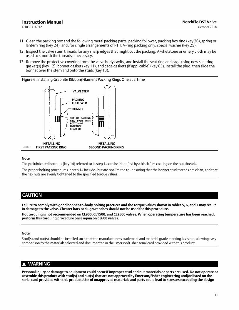
Figure 6. Installing Graphite Ribbon/Filament Packing Rings One at a Time
VALVE STEM
PACKING FOLLOWER
BONNET
TOP OF PACKINGRING EVEN WITHBOTTOM OF ENTRANCE CHAMFER
INSTALLINGSECOND PACKING RINGA2207‐2
INSTALLINGFIRST PACKING RING
Note
The prelubricated hex nuts (key 14) referred to in step 14 can be identified by a black film coating on the nut threads.
The proper bolting procedures in step 14 include‐‐but are not limited to‐‐ensuring that the bonnet stud threads are clean, and thatthe hex nuts are evenly tightened to the specified torque values.
CAUTION
Failure to comply with good bonnet‐to‐body bolting practices and the torque values shown in tables 5, 6, and 7 may resultin damage to the valve. Cheater bars or slug wrenches should not be used for this procedure.
Hot torquing is not recommended on CL900, CL1500, and CL2500 valves. When operating temperature has been reached,perform this torquing procedure once again on CL600 valves.
Note
Stud(s) and nut(s) should be installed such that the manufacturer's trademark and material grade marking is visible, allowing easycomparison to the materials selected and documented in the Emerson/Fisher serial card provided with this product.
WARNING
Personal injury or damage to equipment could occur if improper stud and nut materials or parts are used. Do not operate orassemble this product with stud(s) and nut(s) that are not approved by Emerson/Fisher engineering and/or listed on theserial card provided with this product. Use of unapproved materials and parts could lead to stresses exceeding the design
Instruction ManualD103211X012
NotchFlo DST ValveOctober 2018
12
or code limits intended for this particular service. Install studs with the material grade and manufacturer's identificationmark visible. Contact your Emerson representative immediately if a discrepancy between actual parts and approved partsis suspected.
14. Lubricate the stud threads and the faces of the hex nuts (key 14) with anti‐seize lubricant (not necessary if newfactory prelubricated hex nuts are used). Install the hex nuts and tighten them finger‐tight. Stroke the valve severaltimes to center the trim. Torque the nuts in a crisscross pattern to no more than 1/4 of the nominal torque valuespecified in tables 5, 6, and 7.
When all nuts are tightened to that torque value, increase the torque by 1/4 of the specified nominal torque andrepeat the crisscross pattern. Repeat this procedure until all nuts are tightened to the specified nominal value. Applythe final torque value again and, if any nut still turns, tighten every nut again.
Note
When installing packing rings, prevent entrapping air between the rings. Add the rings one at a time without forcing them belowthe chamfer of the packing box entrance chamber. As each successive ring is added, the stack should not be pushed down morethan the thickness of the added ring (figure 6).
15. Install new packing and the metal packing box parts according to the appropriate arrangement in figures 3, 4, or 5.If desired, packing parts may be pre‐lubricated with a silicon base grease for easier installation. Slip a smooth‐edgedpipe over the valve stem, and gently tap each soft packing part into the packing box, being sure that air is nottrapped between adjacent soft parts.
16. Slide the packing follower, wiper, and packing flange into position. Lubricate the packing flange studs (key 20) andthe faces of the packing flange nuts (key 21). Install the packing flange nuts.
For the spring‐loaded PTFE V‐ring packing shown in figure 3, tighten the packing flange nuts until the shoulder on thepacking follower (key 28) contacts the bonnet.
Note
Lubrication is not recommended on graphite packing.
For graphite packing, tighten the packing flange nuts to the maximum recommended torque shown in table 3 or 4.Then, loosen the packing flange nuts, and retighten them to the recommended minimum torque shown in table 3 or 4.
For other packing types, tighten the packing flange nuts alternately in small equal increments until one of the nutsreaches the minimum recommended torque shown in table 3 or 4. Then, tighten the remaining flange nuts until thepacking flange is level and at a 90‐degree angle to the valve stem.
17. Mount the actuator on the valve body assembly, and reconnect the actuator and valve plug stems according to theprocedures in the appropriate actuator instruction manual.
Trim RemovalKey numbers referenced in this procedure are shown in figures 10 through 17, except where indicated.
1. Remove the actuator and bonnet by following steps 1 through 6 of the replacing packing procedure. Observe allwarnings and cautions in that procedure.

Instruction ManualD103211X012
NotchFlo DST ValveOctober 2018
13
2. Lift the valve stem and attached valve plug out of the valve body. If the valve plug is to be reused, tape or otherwiseprotect the valve plug stem and the valve plug seating surface to prevent scratches.
3. Lift out the cage (key 2), the bonnet gasket (key 11), and (if applicable) the cage gaskets (key 65).
4. Remove the seat ring (key 4) and the seat ring gasket(s) (key 12).
5. Inspect the parts for wear or damage and replace if needed.
6. Refer to the Valve Plug Maintenance procedure or to the Lapping Seats procedure.
Valve Plug MaintenanceKey numbers used in this procedure are shown in figures 10 through 17, except where indicated.
1. With the valve plug (key 5) removed according to the trim removal procedure, proceed as appropriate:
For the NPS 1 and 1‐1/2 CL900 or 1500 and NPS 1 CL2500 NotchFlo DST valves, proceed to step 2.
For all other NotchFlo DST valves, work the retaining ring (key 10) off the valve plug with a screwdriver. Carefully slidethe backup ring, seal ring, and anti‐extrusion rings (keys 9, 8, and 63) off the valve plug.
2. To replace the valve plug stem (key 6), drive out the pin (key 7), and unscrew the stem from the valve plug.
CAUTION
Never reuse an old stem with a new valve plug. Using an old stem with a new plug requires drilling a new pin hole in thestem. This weakens the stem and may cause the stem to fail in service. If a new valve plug is required, always order a valveplug, stem, and pin as an assembly. Specify the correct part number of each of the three parts, but state that the parts arebeing ordered as an assembly.
A used valve plug may be reused with a new stem.
3. Thread the new stem into the valve plug and tighten it to the appropriate torque value given in table 8. Using thevalve plug pin hole as a guide, drill the pin hole through the stem. Refer to table 8 for drill sizes.
4. Drive in the pin to lock the assembly.
5. If it is necessary to lap the seating surfaces, complete the lapping seats procedure before installing the seal ring. TheTrim Replacement procedure provides seal ring installation instructions and valve reassembly instructions.
Lapping SeatsKey numbers referenced in this procedure are shown in figures 10 through 17, except where indicated.
With metal‐seat constructions, lapping seating surfaces of the valve plug and seat ring (keys 5 and 4) can improveshutoff. (Deep nicks should be machined out rather than ground out.) Use a good quality lapping compound of amixture of 280 to 600‐grit. Apply the compound to the bottom of the valve plug.
Note
NotchFlo DST valves use spiral‐wound gaskets. These gaskets provide their seal by being crushed and therefore should never bereused. This includes reusing a gasket after the lapping procedure has been performed.
An “old” gasket can be used to lap the seat, however the gasket must be replaced with a new gasket.
To preserve the effects of lapping, do not change either the position of the seat ring in the valve body cavity or the position of thecage on the seat ring after lapping the seating surfaces. When the parts are removed for cleaning and replacement of the “old”gaskets, return them to the original positions.

Instruction ManualD103211X012
NotchFlo DST ValveOctober 2018
14
Use the following procedure to lap the seating surfaces.
1. Install the following parts according to the instructions presented in the trim replacement procedure: “old” seatring gasket(s) (key 12), seat ring (key 4), cage (key 2), “old” bonnet gasket(key 11), and (if applicable) the “old”cage gaskets (key 65).
2. Proceed as appropriate:
For a NotchFlo DST balanced valve, install the valve plug and stem assembly (keys 5 and 6)‐‐without seal ring (key 8)‐‐into the cage.
For a NotchFlo DST unbalanced valve, install the valve plug and stem assembly (keys 5 and 6) into the cage.
3. Install the bonnet (key 18) over the valve stem, and secure the bonnet with four of the hex nuts (key 14).
4. Attach a handle, such as a piece of strap iron secured by stem locknuts, to the valve stem. Rotate the handlealternately in each direction to lap the seats.
5. After lapping, disassemble as necessary (you may mark the position of the seat ring and cage with a soft tipmarker). Clean the seating surfaces, replace the gaskets, reassemble (taking care to return the seat ring and cage totheir original positions), and test for shutoff. Repeat the lapping procedure if necessary.
Trim Replacement
WARNING
Observe the warning at the start of the Maintenance section.
After all trim maintenance has been completed, reassemble the valve body by following the numbered steps below. Becertain that all gasketed surfaces have been well cleaned. Key numbers referenced in this procedure are shown infigures 10 through 16, except where indicated.
CAUTION
Inspect the seat ring, cage, bonnet, and body gasket surfaces. These surfaces must be in good condition, with all foreignmaterial removed. Small burrs less than approximately 0.076 mm (0.003 inches) in height (the thickness of a human hair)can be ignored. Scratches or burrs that run across the serrations are not permitted under any conditions, since they willprevent the gaskets from sealing properly.
1. Install the seat ring gasket (key 12) into the valve body. Install the seat ring (key 4).
2. For CL600, CL900, CL1500 4-Stage ≤ NPS 4, CL1500 6-Stage ≤ NPS 3 and CL2500 ≤ NPS 3 valves, install the secondseat ring gasket (key 12) onto the seat ring. For CL1500 4-Stage ≥ NPS 6, CL1500 6-Stage ≥ NPS4 and CL2500 ≥ NPS 4 valves, install the first cage gasket (key65) onto the seat ring.
3. Install the cage.
4. For a NotchFlo DST balanced valve, install the anti‐extrusion rings (key 63) onto the valve plug (key 5). Install theseal ring (key 8) onto the valve plug (key 5). Install the ring with the open side facing the valve plug stem end of thevalve plug for flow‐up applications (view A of figures 10 through 16). Slide the backup ring (key 9) onto the valveplug. Secure with the retaining ring (key 10).
5. Install the valve plug into the cage.
6. Install the bonnet gasket (key 11). For CL1500 4-Stage ≥ NPS 6, CL1500 6-Stage ≥ NPS4 and CL2500 ≥ NPS4 valves,install the second cage gasket (key 65) onto the cage.

Instruction ManualD103211X012
NotchFlo DST ValveOctober 2018
15
7. Install the bonnet over the valve stem and onto the valve body.
Note
The prelubricated hex nuts (key 14) referred to in step 8 can be identified by a black film coating on the nut threads.
The proper bolting procedures in step 8 include‐‐but are not limited to‐‐ensuring that the bonnet stud threads are clean, and thatthe hex nuts are evenly tightened to the specified torque values.
Table 9. Actuator Groups by Type NumberGroup 1
71 & 90 mm (2‐13/16 and 3‐9/16 Inch) Yoke BossGroup 100
127 mm (5‐Inch) Yoke Boss
585C657 & 667
1008
585C657
Group 101127 mm (5‐Inch) Yoke Boss
667
CAUTION
Failure to comply with good bonnet‐to‐body bolting practices and the torque values shown in tables 5, 6, and 7 may resultin damage to the valve. Cheater bars or slug wrenches should not be used for this procedure.
Hot torquing is not recommended on CL900, CL1500, and CL2500 valves. When operating temperature has been reached,perform this torquing procedure once again on CL600 valves.
Note
Stud(s) and nut(s) should be installed such that the manufacturer's trademark and material grade marking is visible, allowing easycomparison to the materials selected and documented in the Emerson/Fisher serial card provided with this product.
WARNING
Personal injury or damage to equipment could occur if improper stud and nut materials or parts are used. Do not operate orassemble this product with stud(s) and nut(s) that are not approved by Emerson/Fisher engineering and/or listed on theserial card provided with this product. Use of unapproved materials and parts could lead to stresses exceeding the designor code limits intended for this particular service. Install studs with the material grade and manufacturer's identificationmark visible. Contact your Emerson representative immediately if a discrepancy between actual parts and approved partsis suspected.
8. Lubricate the stud threads and the faces of the hex nuts (key 14) with anti‐seize lubricant (not necessary if newfactory prelubricated hex nuts are used). Install the hex nuts, but do not tighten them. Torque the nuts in acrisscross pattern to no more than 1/4 of the nominal torque value specified in table 5, 6, or 7. When all nuts aretightened to that torque value, increase the torque by 1/4 of the specified nominal torque and repeat the crisscrosspattern. Repeat this procedure until all nuts are tightened to the specified nominal value. Apply the final torquevalue again and, if any nut still turns, tighten every nut again.
9. Install new packing and packing box parts per steps 15 and 16 of the Replacing Packing procedure. Be certain toobserve the note given prior to step 15 of that procedure.
10. Mount the actuator by following the procedures in the actuator instruction manual. Check for packing leakage asthe valve is being put into service. Retorque the packing flange nuts as required. See tables 3 and 4.

Instruction ManualD103211X012
NotchFlo DST ValveOctober 2018
16
Parts OrderingEach valve body‐bonnet assembly is assigned a serial number which can be found on the valve. This same number alsoappears on the actuator nameplate when the valve is shipped from the factory as part of a control valve assembly.Refer to the serial number when contacting your Emerson sales office for technical assistance. When orderingreplacement parts, reference the valve serial number to obtain the correct eleven‐character part number for each part;the following Parts Kit and Parts List is for information only.
WARNING
Use only genuine Fisher replacement parts. Components that are not supplied by Emerson Automation Solutions shouldnot, under any circumstances, be used in any Fisher valve, because they may void your warranty, might adversely affect theperformance of the valve, and could cause personal injury and property damage.
Parts KitsStandard Packing Repair Kits (Non Live‐Loaded)
Stem Diameter, mm (Inches)Yoke Boss Diameter, mm (Inches)
12.7 (1/2)71 (2‐13/16)
19.1 (3/4)90 (3‐9/16)
25.4 (1)127 (5)
31.8 (1-1/4)127 (5, 5H)
PTFE (Contains keys 22, 24, 25, 26, 27) RPACKX00022 RPACKX00032 RPACKX00342 RPACKX00352
Double PTFE (Contains keys 22, 24, 26, 27) RPACKX00052 RPACKX00062 RPACKX00362 RPACKX00372
Single Graphite Ribbon/Filament (Contains keys 23 [ribbon ring], 23 [filament ring], 24, and 26)
RPACKX00112 RPACKX00122 - - - - - -
Single Graphite Ribbon/Filament (Contains keys 23 [ribbon ring], 23 [filament ring], and 26)
- - - - - - RPACKX00532 RPACKX00542
Single Graphite Ribbon/Filament (Contains keys 23 [ribbon ring], 23 [filament ring])
RPACKX00142 RPACKX00152 - - - - - -
ENVIRO‐SEAL™ Packing Retrofit Kits
Retrofit kits include parts to convert valves with existing standard bonnets to the ENVIRO‐SEAL packing boxconstruction.
Refer to figure 7 for key numbers for PTFE packing, to figure 8 for key numbers for Graphite ULF packing, and to figure9 for key numbers for duplex packing.
PTFE kits include keys 200, 201, 211, 212, 214, 215, 217, 218, tag, and cable tie. Graphite ULF kits include keys 200,201, 207, 208, 209, 210, 211, 212, 214, 216, 217, tag, and cable tie. Duplex kits include keys 200, 201, 207, 209, 211,212, 214, 215, 216, 217, tag, and cable tie.
Stems and packing box constructions that do not meet Fisher stem finish specifications, dimensional tolerances, anddesign specifications may adversely alter the performance of this packing kit.
For part numbers of individual components in the ENVIRO‐SEAL packing kits, refer to instruction manual ENVIRO‐SEALPacking System for Sliding‐Stem Valves, D101642X012.
ENVIRO‐SEAL Packing Retrofit Kits
PACKINGMATERIAL
STEM DIAMETER AND YOKE BOSS DIAMETER, mm (INCH)
12.7 (1/2)71 (2‐13/16)
19.1 (3/4)90 (3‐9/16)
25.4 (1)127 (5)
31.8 (1‐1/4)127 (5, 5H)
Double PTFE RPACKXRT022 RPACKXRT032 RPACKXRT042 RPACKXRT052
Graphite ULF RPACKXRT272 RPACKXRT282 RPACKXRT292 RPACKXRT302
Duplex RPACKXRT222 RPACKXRT232 RPACKXRT242 RPACKXRT252

Instruction ManualD103211X012
NotchFlo DST ValveOctober 2018
17
ENVIRO‐SEAL Packing Repair Kits
Repair kits include parts to replace the “soft” packing materials in valves that already have ENVIRO‐SEAL packingarrangements installed or in valves that have been upgraded with ENVIRO‐SEAL retrofit kits.
Refer to figure 7 for key numbers for PTFE packing, to figure 8 for key numbers for Graphite ULF packing, and to figure9 for key numbers for duplex packing.
PTFE repair kits include keys 214, 215, and 218. Graphite ULF repair kits include keys 207, 208, 209, 210, and 214.Duplex repair kits include keys 207, 209, 214, and 215.
Stems and packing box constructions that do not meet Fisher stem finish specifications, dimensional tolerances, anddesign specifications may adversely alter the performance of this packing kit.
For part numbers of individual components in the ENVIRO‐SEAL packing kits, refer to instruction manual ENVIRO‐SEALPacking System for Sliding‐Stem Valves, D101642X012.
ENVIRO‐SEAL Packing Repair KitsStem Diameter, mm (Inches)
Yoke Boss Diameter, mm (Inches)12.7 (1/2)
71 (2‐13/16)19.1 (3/4)
90 (3‐9/16)25.4 (1)127 (5)
31.8 (1‐1/4)127 (5, 5H)
Double PTFE (Contains keys 214, 215, & 218) RPACKX00202 RPACKX00212 RPACKX00222 RPACKX00232
Graphite ULF (Contains keys 207, 208, 209, 210, and 214) RPACKX00602 RPACKX00612 RPACKX00622 RPACKX00632
Duplex (Contains keys 207, 209, 214, and 215) RPACKX00302 RPACKX00312 RPACKX00322 RPACKX00332

Instruction ManualD103211X012
NotchFlo DST ValveOctober 2018
18
Gasket Kits
RatingValve Size,
NPSKey
NumberPart Number Rating
Valve Size,NPS
KeyNumber
Part Number
CL300/CL600 1
Set RGASKETXC72CL1500
(6-stage)1
Set RGASKETXD42
11 1R2859X0042 11 12B6757X012
12 12B6758X012 (qty 2) 12 12B6758X012 (qty 2)
CL300/CL600 2
Set RGASKETXC82CL1500
(6-stage)2
Set RGASKETXD52
11 1R3299X0042 11 12B6756X012
12 1R309999442 (qty 2) 12 12B6755X012 (qty 2)
CL300/CL600 3
Set RGASKETXC92CL1500
(6-stage)3
Set RGASKETXE32
11 1R3484X0042 11 GG03231X012
12 1R384599442 (qty 2) 12 GG03232X012 (qty 2)
CL300/CL600 4
Set RGASKETXD12
CL1500(6-stage)
4
Set RGASKETXE42
11 1R3724X0042 11 GE26454X012
12 1L8270X0012 (qty 2) 12 GE26456X012
CL300/CL600 6
Set RGASKETXD22 65 10B5309X012 (qty 2)
12 GG04987X012 68 18A8275X012
65 GG01635X012 (qty 2)
CL1500(6-stage)
6
Set RGASKETXE52
CL300/CL600 8
Set RGASKETXD32 11 GE26179X012
11 1U5081X0052 12 GE26181X012
12 1U508599442 (qty 2) 65 1P3680X0012 (qty 3)
65 1U508599442 68 GG14893X012
67 16A1942X012
CL2500 1
Set RGASKETXE12
CL900/CL1500 1
Set RGASKETXD42 11 12B9359X042
11 12B6757X012 12 12B9360X052 (qty 2)
12 12B6758X012 (qty 2)
CL2500 2
Set RGASKETXE22
CL900/CL1500 1-1/2
Set RGASKETXD42 11 12B4274X042
11 12B6757X012 12 12B4275X042 (qty 2)
12 12B6758X012 (qty 2)
CL2500 3
Set RGASKETXE32
CL900/CL1500 2
Set RGASKETXD52 11 GG03231X012
11 12B6756X012 12 GG03232X012 (qty 2)
12 12B6755X012 (qty 2)
CL2500 4
Set RGASKETXE42
CL900/CL1500 3
Set RGASKETXD62 11 GE26454X012
11 12B6027X012 12 GE26456X012
12 12B6030X012 (qty 2) 65 10B5309X012 (qty 2)
CL900/CL1500 4
Set RGASKETXD72 68 18A8275X012
11 12B9350X012
CL2500 6
Set RGASKETXE52
12 12B9351X012 (qty 2) 11 GE26179X012
CL900/CL1500 6
Set RGASKETXD82 12 GE26181X012
11 GE26041X012 65 1P3680X0012 (qty 3)
12 GE26043X012 68 GG14893X012
65 GE26042X012 (qty 2)
CL900/CL1500 8
Set RGASKETXD92
11 GE25826X012
12 GE25828X012
65 GE25827X012 (qty 3)

Instruction ManualD103211X012
NotchFlo DST ValveOctober 2018
19
Figure 7. Typical ENVIRO‐SEAL Packing System withPTFE Packing
A6297‐1
Figure 8. Typical ENVIRO‐SEAL Packing System withGraphite ULF Packing
PACKINGRING(KEY 209)
PACKINGRING(KEY 210)
PACKINGBOX RING(KEY 211)
STUD(KEY 200)
SPRINGPACK
ASSEMBLY(KEY 217)
HEX NUT(KEY 212)
PACKINGFLANGE(KEY 201)
GUIDEBUSHING(KEY 207)
PACKINGWASHERS(KEY 214)
GUIDEBUSHING(KEY 208)
39B4612/A
Figure 9. Typical ENVIRO‐SEAL Packing System withDuplex Packing
200
212
201
215
216
207
209
211
217
207
207
207
214
213
A6722

Instruction ManualD103211X012
NotchFlo DST ValveOctober 2018
20
Parts ListNumerous available combinations of valve parts make selection of some parts difficult; when ordering valve parts forwhich a part number is not listed, provide the valve serial number with the order, permitting proper selection ofreplacement parts to be made at the factory.
Note
For part numbers not shown, contact your Emerson sales office.
Key Description
1 Valve Body ‐‐‐
If you need a valve body as a replacement
part, order by valve size, serial number,
and desired material.
2* Cage
4* Seat Ring
5* Valve Plug or Plug/Stem Assembly
6* Valve Stem
7* Pin
8* Seal Ring
9* Back Up Ring
10* Retaining Ring
11* Bonnet Gasket
12* Seat Ring Gasket
13 Stud, Cont Thd
14 Hex Nut
15 Anti‐Seize Lubricant
Key Description
16 Nameplate (not shown)
17 Wire (not shown)
18 Bonnet‐‐‐
If you need a bonnet as a replacement
part, order by valve size and stem
diameter, serial number, and desired material.
19 Packing Flange
20 Stud Bolt
21 Hex Nut
22* Packing Set
23* Packing Ring
24 Spring or Lantern Ring
25 Washer, Special
26* Packing Box Ring
27* Upper Wiper
28 Follower
29 Stud Bolt
30 Hex Nut
32 Yoke Locknut
38 Drive Screw
41 Flow Arrow
63* Anti‐Extrusion Ring
65* Cage Gasket
CL1500, NPS 6, qty 1
CL1500, NPS 8 and CL2500, qty 2
66* Carbon Steel Washer
68 Gasket
*Recommended spare parts

Instruction ManualD103211X012
NotchFlo DST ValveOctober 2018
21
Figure 10. Fisher NotchFlo DST CL600 Balanced Globe Valve Assembly (NPS 1 through 8)
GE14589
� APPLY LUB
5-INCHYOKE BOSS
VIEW A
FLOW
A

Instruction ManualD103211X012
NotchFlo DST ValveOctober 2018
22
Figure 11. Fisher NotchFlo DST CL900 and 1500 Unbalanced Globe Valve Assembly (NPS 1 to 1-1/2)
GG11704‐A
� APPLY LUB
FLOW
FLOW UP

Instruction ManualD103211X012
NotchFlo DST ValveOctober 2018
23
Figure 12. Fisher NotchFlo DST CL900 and 1500 Balanced Globe Valve Assembly (NPS 2 through 4)
GE14166‐A
� APPLY LUB
5-INCHYOKE BOSS
VIEW A
FLOW
FLOW UP
A

Instruction ManualD103211X012
NotchFlo DST ValveOctober 2018
24
Figure 13. Fisher NotchFlo DST CL900 and 1500 Unbalanced Angle Valve Assembly (NPS 1 to 1‐1/2)
GE14052‐A
� APPLY LUB
NOTE: NotchFlo FORGED BLOCK ANGLE VALVE BODIES UTILIZEDRILLED AND TAPPED LINE FLANGE BOLTING CONNECTIONS.
FLOW UP
FLOW
Instruction ManualD103211X012
NotchFlo DST ValveOctober 2018
25
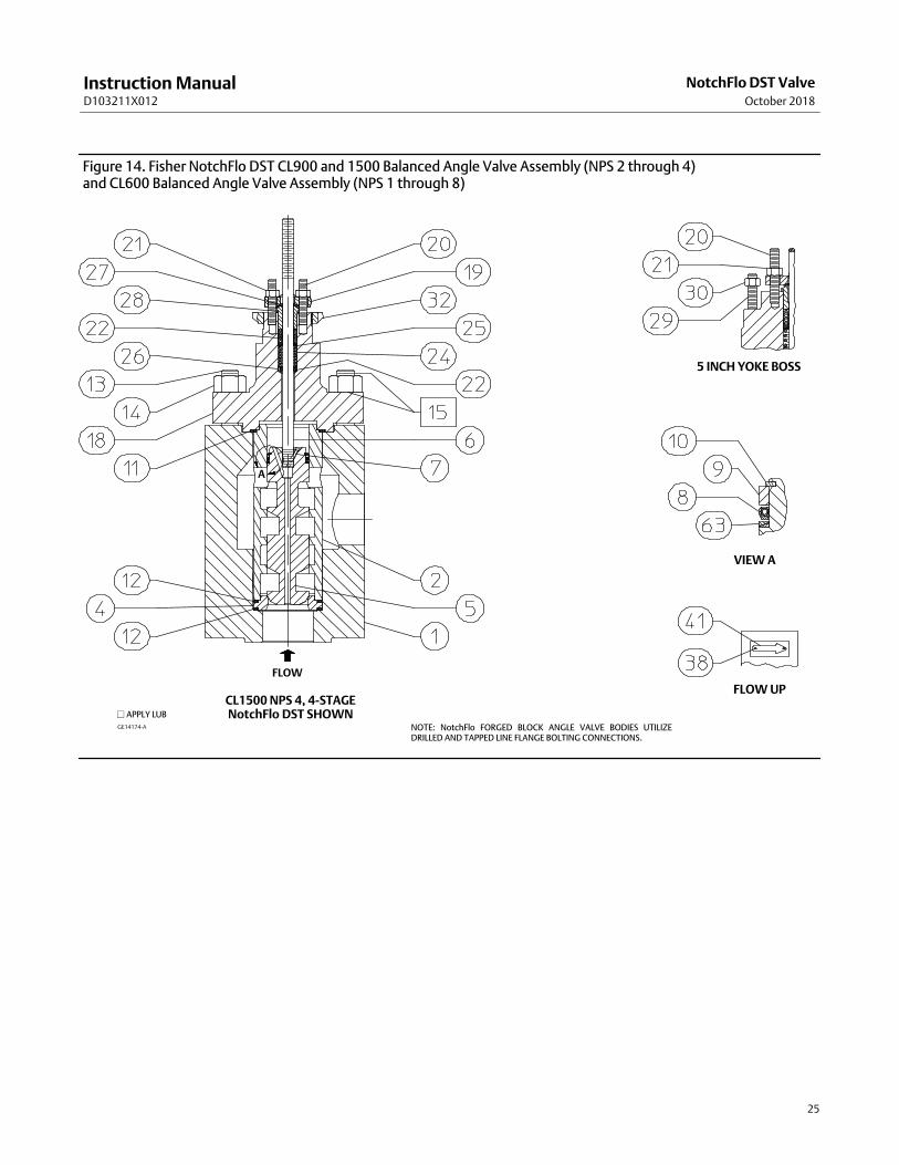
Figure 14. Fisher NotchFlo DST CL900 and 1500 Balanced Angle Valve Assembly (NPS 2 through 4) and CL600 Balanced Angle Valve Assembly (NPS 1 through 8)
GE14174‐A
� APPLY LUB
NOTE: NotchFlo FORGED BLOCK ANGLE VALVE BODIES UTILIZEDRILLED AND TAPPED LINE FLANGE BOLTING CONNECTIONS.
CL1500 NPS 4, 4-STAGENotchFlo DST SHOWN
FLOW
FLOW UP
VIEW A
5 INCH YOKE BOSS
A

Instruction ManualD103211X012
NotchFlo DST ValveOctober 2018
26
Table 10. Block Forged Valve Body Line Bolting
Valve Size, NPS Rating Bolt Information Depth of ThreadQuantity
(Inclusive of Inlet andOutlet Flange)
1
CL300/600
5/8-11 UNC-2B 0.94 8
2 5/8-11 UNC-2B 0.94 16
3 3/4-10 UNC-2B 1.13 16
4CL600 7/8-9 UNC-2B 1.32 16
CL300 3/4-10 UNC-2B 1.13 16
6CL600 1-8 UN-2B 1.5 24
CL300 3/4-10 UNC-2B 1.23 24
8CL600 1 1/8-8 UN-2B 1.69 24
CL300 7/8-9 UNC-2B 1.31 24
1
CL900/1500
7/8-9 UNC-2B 1.31 8
1-1/2 1-8 UNC-2B 1.5 8
2 7/8-9 UNC-2B 1.31 16
3CL900 7/8-9 UNC-2B 1.31 16
CL1500 1 1/8-8 UN-2B 1.69 16
4
CL9001 1/8-8 UN-2B 1.41 2
1 1/8-8 UN-2B 1.69 14
CL1500
1 1/4-8 UN-2B 1.45 4
1 1/4-8 UN-2B 1.50 4
1 1/4-8 UN-2B 1.88 8
6 CL15001 3/8-8 UN-2B 1.72 6
1 3/8-8 UN-2B 2.06 18
8 CL15001 5/8-8 UN-2B 1.8 2
1 5/8-8 UN-2B 2.44 22
1 CL2500 7/8-9 UNC-2B 1.31 8
2 CL2500 1-8 UNC-2B 1.5 16
3 CL2500 1 1/4-8 UN-2B 1.87 16
4 CL2500
1 1/2-8 UN-2B 1.65 2
1 1/2-8 UN-2B 2.25 6
1 1/2-8 UN-2B 2.13 8
6 CL2500
2-8 UN-2B 2.5 2
2-8 UN-2B 3 6
2-8 UN-2B 2.65 8
Instruction ManualD103211X012
NotchFlo DST ValveOctober 2018
27
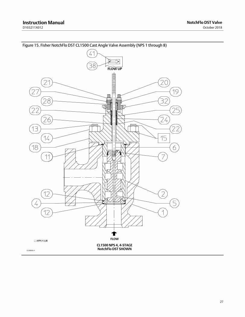
Figure 15. Fisher NotchFlo DST CL1500 Cast Angle Valve Assembly (NPS 1 through 8)
GG08666-A
� APPLY LUB
CL1500 NPS 4, 4-STAGENotchFlo DST SHOWN
FLOW
FLOW UP

Instruction ManualD103211X012
NotchFlo DST ValveOctober 2018
28
Figure 16. Fisher NotchFlo DST CL1500 � NPS 6 and CL2500 Balanced Angle Valve Assembly
NOTE: NotchFlo FORGED BLOCK ANGLE VALVE BODIES UTILIZEDRILLED AND TAPPED LINE FLANGE BOLTING CONNECTIONS.
CL1500 NPS 6, 4-STAGE NotchFlo DST SHOWN
FLOW UP
VIEW A
5 INCH YOKE BOSS
A
FLOWAPPLY LUB

Instruction ManualD103211X012
NotchFlo DST ValveOctober 2018
29
Figure 17. Fisher NotchFlo DST CL1500 6-Stage Globe Valve Assembly
NOTE: PARTS NOT SHOWN: 16-NAMEPLATE, 17-WIRE
FLOW UP
VIEW A
VIEW A
FLOW
GG56616
� APPLY LUB
VIEW A

Instruction ManualD103211X012
NotchFlo DST ValveOctober 2018
30

Instruction ManualD103211X012
NotchFlo DST ValveOctober 2018
31

Instruction ManualD103211X012
NotchFlo DST ValveOctober 2018
32
Emerson Automation Solutions Marshalltown, Iowa 50158 USASorocaba, 18087 BrazilCernay 68700 FranceDubai, United Arab EmiratesSingapore 128461 Singapore
www.Fisher.com
The contents of this publication are presented for informational purposes only, and while every effort has been made to ensure their accuracy, they are notto be construed as warranties or guarantees, express or implied, regarding the products or services described herein or their use or applicability. All sales aregoverned by our terms and conditions, which are available upon request. We reserve the right to modify or improve the designs or specifications of suchproducts at any time without notice.
� 2005, 2018 Fisher Controls International LLC. All rights reserved.
Fisher, NotchFlo, and ENVIRO-SEAL are marks owned by one of the companies in the Emerson Automation Solutions business unit of Emerson Electric Co.Emerson Automation Solutions, Emerson, and the Emerson logo are trademarks and service marks of Emerson Electric Co. All other marks are the propertyof their respective owners.
Neither Emerson, Emerson Automation Solutions, nor any of their affiliated entities assumes responsibility for the selection, use or maintenanceof any product. Responsibility for proper selection, use, and maintenance of any product remains solely with the purchaser and end user.