fishhook maneuver test procedure - safercar general ... specifications for the data acquisition...
TRANSCRIPT

-1
Laboratory Test Procedure for Dynamic Rollover
The Fishhook Maneuver Test Procedure
New Car Assessment Program (NCAP)
MARCH 2013
U.S. Department of Transportation
National Highway Traffic Safety Administration 1200 New Jersey Avenue SE
Washington, DC 20590

-2
LABORATORY TEST PROCEDURE TABLE OF CONTENTS
1.0 INTRODUCTION ................................................................................................... 4
1.1 General ................................................................................................................ 4
1.2 Rollover Resistance Requirements of the TREAD Act ................................ 4
1.3 Recent NHTSA Light Vehicle Dynamic Rollover Propensity Research .... 4
2.0 TEST EQUIPMENT .............................................................................................. 5
2.1 Vehicle Load Configurations ............................................................................ 5
2.2 Safety Outriggers ............................................................................................... 7
2.3 Tires ..................................................................................................................... 8
2.4 Data Collection ................................................................................................... 9
2.5 Instrumentation ................................................................................................ 10
2.6 Steering Machine ............................................................................................. 14
3.0 TEST MANEUVERS ........................................................................................... 14
3.1 Slowly Increasing Steer .................................................................................. 14
3.2 NHTSA Fishhook Maneuver .......................................................................... 17
4.0 ITEMS PERTAINING TO TEST CONDUCT ................................................... 26
4.1 Definition of Two-Wheel Lift ........................................................................... 26
4.2 Vehicle Test Configurations ........................................................................... 26
4.3 Road Test Surface .......................................................................................... 27
4.4 Ambient Conditions ......................................................................................... 28
4.5 Calibration Data ............................................................................................... 28

-3
4.6 Tire Break-In Procedure ................................................................................. 29
4.7 Static Datums ................................................................................................... 29
4.8 Vehicle Gear Selection ................................................................................... 30
4.9 Outrigger Adjustment ...................................................................................... 30
4.10 Videotape Documentation ......................................................................... 31
4.11 Summary of Tests To Be Performed For Each Vehicle........................ 31
4.12 Summary of Metrics Measured For Each Vehicle ................................. 32
4.13 Post Processing .......................................................................................... 32
5.0 REFERENCES .................................................................................................... 33

-4
FISHHOOK MANEUVER TEST PROCEDURE 1.0 INTRODUCTION
1.1 General
This document describes the test procedure used by the National Highway Traffic Safety Administration's (NHTSA) New Car Assessment Program (NCAP) to evaluate light vehicle dynamic rollover propensity. The procedure is comprised of one characterization maneuver and one rollover resistance maneuver.
1.2 Rollover Resistance Requirements of the TREAD Act
Section 12 of the "Transportation Recall, Enhancement, Accountability and Documentation (TREAD) Act of November 2000" reflects the desire of Congress to supplement SSF [Static Stability Factor] with a dynamic stability test using vehicle maneuvers. Congress directed NHTSA to "develop a dynamic test on rollovers by motor vehicles for a consumer information program; and carry out a program conducting such tests." NHTSA's NCAP Light Vehicle Dynamic Rollover Propensity Test Procedure described in this document was developed as part of NHTSA's effort to fulfill the requirements of the TREAD Act.
1.3 Recent NHTSA Light Vehicle Dynamic Rollover Propensity Research
During the spring through fall of 2001 NHTSA performed an extensive assessment of many test track maneuvers potentially capable of quantifying on-road, non-tripped vehicle rollover propensity. In brief, five vehicle characterization and nine dynamic rollover propensity maneuvers were studied. Each maneuver was either discarded or retained for subsequent program phases. The 2001 research project is documented in [1].

-5
During the spring through fall of 2002 NHTSA performed a comprehensive evaluation of rollover resistance for a broad spectrum of twenty-six light vehicles. The test vehicles were evaluated with one Characterization maneuver and two Rollover Resistance maneuvers. Up to two load configurations per vehicle were used. The 2002 research project is documented in [2].
2.0 TEST EQUIPMENT
2.1 Vehicle Load Configurations
NHTSA's dynamic rollover propensity test procedure uses one of two loading configurations: Nominal or Multi-Passenger. A description of each configuration is provided below.
Both vehicle load configurations include instrumentation, a steering machine, and outriggers. Test vehicle bumper assemblies are removed for outrigger installation. The reduction in vehicle weight due to the removal of the bumpers is offset by the additional weight of the outriggers and their mounting system. The outrigger system typically outweighs the bumper assemblies.
2.1.1 Nominal Load Configuration
The Nominal Load Configuration consists of the driver, instrumentation, steering machine, outriggers, and full tank of fuel. Weight and location specifications for the data acquisition system and steering machine are presented in Table A.1 and Fig A.1.
Non-pickup truck vehicles with only front designated seating positions use the Nominal Load Configuration.

-6
Table A.1. Equipment Location and Weight
Equipment Location Weight,
typical (lbs)
Data Acquisition System
Front passenger seat 58
Steering Machine Handwheel 31
Steering Machine Electronics Box
Passenger row foot well behind the front passenger seat. If vehicle does not have a rear passenger row foot well, the Electronics Box should be placed in the front passenger seat foot well.
39
2.1.2 Multi-Passenger Configuration
The Multi-Passenger Configuration includes all elements of the Nominal Load Configuration plus ballast in the form of water dummies. Water dummies are installed as follows:
For vehicles with three or more designated rear seating positions, three 175 lb. water dummies are used. The water dummies shall be positioned on the rear seats (second seating row) closest to driver and front passenger seats (first seating row). If there are only two seating positions in the second seating row, the third water dummy shall be placed in the center of the third seating row, provided it is a designated seating position. Refer to Fig A.2.
For vehicles with two designated rear seating positions, two 175 lb. water dummies shall be positioned in the rear seats. Refer to Fig A.3.

-7
For pickups with only front designated seating positions, three 175 lb. water dummies will be used. The water dummies shall be positioned behind the cab in a manner that emulates a second seating row. If it is not possible to fit three water dummies directly behind the cab, the third water dummy shall be placed in the center of a simulated third seating row. Refer to Fig A.4.
For pickups with two seating rows, three 175 lb. water dummies will be used. If the second seating row includes three designated seating positions, each water dummy shall be placed in these positions. If the second seating row includes two designated seating positions, two 175 lb. water dummies shall be positioned in the second seating row of the cab, and the third water dummy shall be positioned behind the cab in a manner that emulates the center seating position of a third seating row. Refer to Fig A.5.
For all vehicles, if the Multi-Passenger Configuration results in the vehicle exceeding its Gross Vehicle Weight Rating (GVWR) and/or rear Gross Axle Weight Rating (GAWR), the weight of each dummy will be equally reduced until the GVWR and/or rear GAWR are no longer exceeded. The weight of the water dummies shall not be reduced if only the front GAWR is exceeded and the front axle weight does not exceed the front GAWR by more than 50 pounds, i.e., if the Multi-Passenger Configuration results in the vehicle exceeding its front GAWR, and its GVWR and/or rear GAWR, the weight of each dummy will be equally reduced until the GVWR and rear GAWR are no longer exceeded and the front GAWR is not exceeded by more than 50 pounds.
For non-pickup truck vehicles with only front designated seating positions, the Multi-Passenger Configuration is omitted from the test matrix.
2.2 Safety Outriggers
Safety outriggers are installed on all test vehicles during all test maneuvers. NHTSA uses outriggers machined from 6Al-4V titanium. NHTSA's "short" outriggers are used for vehicles with baseline weights under 3,500 pounds in a baseline condition (as delivered); "standard" outriggers are used for vehicles with

-8
baseline weights from 3,500 and 7,000 pounds; and "long" outriggers are used for vehicles with baseline weights from 7,001 to 10,000 pounds. Information on NHTSA's titanium outrigger system is documented in [3].
2.3 Tires
All tires must be new, and of the same make, model, size, and DOT specification of those installed on vehicles when purchased new. Tire inflation pressures are to be in accordance with the recommendations indicated on each vehicle's identification placard.
2.3.1 Tire Mounting Technique
When mounting tires to the rims used for testing, no tire mounting lubricant should be used. Lubricant is not used due to uncertainty surrounding the occurrences of tire debeading observed during NHTSA's rollover research. To eliminate the possibility of tire lubricant contributing to this phenomenon, it should not be used. Because no lubricant is used, care must be taken to confirm that the tire is fully seated on the wheel rim at the completion of the mounting procedure.
2.3.2 Frequency of Tire Changes
To minimize the effects of tire wear on vehicle response and rollover propensity, rollover research requires frequent tire changes. For each loading condition, the following guidelines must be followed:
– One set of tires is to be used for each Slowly Increasing Steer test series. Each series is comprised of left and right steer tests.
– Up to two tire sets are to be used for the Fishhook maneuver test series. The actual number of tire sets used is dependent on the response of each vehicle. The tire change protocol is presented in the Fishhook maneuver test procedure (Section 3.2). Note: A tire

-9
change between the completion of the Slowly Increasing Steer maneuver and initiation of Fishhook testing is not required provided the abbreviated Slowly Increasing Steer procedure described in Section 3.1.2 is used. If the abbreviated procedure is not used (i.e., the maneuver is performed such that maximum lateral acceleration is achieved), a tire change between the completion of the Slowly Increasing Steer maneuver and initiation of Fishhook testing is required, as tire wear associated with these tests may potentially confound Fishhook test outcome.
2.3.3 Use of Inner Tubes
Fishhook maneuvers have been shown to produce debeading of the outside front and rear tires. The occurrence of debeading can result in significant damage to the test surface. NHTSA research has concluded the easiest, most cost effective way to minimize debeading is the use of inner tubes designed for radial tires. Inner tubes must be installed prior to any Fishhook test - one inner tube for each of the vehicle's tires. Inner tubes should be appropriately sized for the test vehicle's tires.
Installation of inner tubes is not required prior to Slowly Increasing Steer tests, regardless of vehicle or load condition.
2.4 Data Collection
All data is to be sampled at 200 Hz. NHTSA's signal conditioning consists of amplification, anti-alias filtering, and digitizing. Amplifier gains are selected to maximize the signal-to-noise ratio of the digitized data. Filtering is performed with two-pole low-pass Butterworth filters with nominal cutoff frequencies selected to prevent aliasing. The nominal cutoff frequency is 15 Hz (calculated breakpoint frequencies are 18 and 19 Hz for the first and second poles respectively).

-10
Data collection is initiated manually by the test driver immediately before the start of the maneuver or automatically initiated by the "Handwheel Command Flag" signal from the steering machine (refer to Section 3.2.4.2.2, Handwheel Command Flag).
2.5 Instrumentation
Each test vehicle is to be equipped with sensors, a data acquisition system, and a programmable steering machine. Equipment location and weight specifications are presented in Table A.1 and Fig A.1.
2.5.1 Sensors and Sensor Locations
Table A.2 lists the sensors required by NHTSA's dynamic rollover propensity test procedure. A brief description of these sensors is provided in this section.
2.5.1.1 Handwheel Angle
Handwheel position is measured via an angle encoder integral with the programmable steering machines.
2.5.1.2 Vehicle Speed
Vehicle speed is measured with a non-contact speed sensor placed at the center rear of each vehicle. NHTSA has had good experiences with the use of Doppler radar based sensors. Sensor outputs are to be transmitted not only to the data acquisition system, but also to a dashboard display unit. This allows the driver to accurately monitor vehicle speed.
Table A.2. Recommended Sensor Specifications

-11
Type Output Range Resolution Accuracy
Multi-Axis Inertial Sensing System
Longitudinal, Lateral, and Vertical Acceleration
Roll, Yaw, and Pitch Rate
Accelerometers: ±2 g
Angular Rate Sensors: ±100 deg/s
Accelerometers: ≤10 ug
Angular Rate Sensors: ≤0.004 deg/s
Accelerometers: ≤0.05% of full range
Angular Rate Sensors: 0.05% of full range
Angle Encoder Handwheel Angle ±800 deg 0.25 deg ±0.25 deg
Ultrasonic Distance Measuring System
Left and Right Side Vehicle Height
5 - 24 inches 0.01 inches ±0.25% of maximum distance
Load Cell Brake Pedal Force 0 - 300 lbf N/A N/A
Radar Speed Sensor Vehicle Speed 0.1 - 125 mph 0.009 mph ±0.25% of full
scale
Infrared Distance Measuring System
Wheel Lift 13.75 - 33.5 inches
0.01 in., short range
0.3 in., long range ±1% of full scale
Data Flag (Handwheel Command Flag)
Pauses in commanded steering inputs
0 - 10 V N/A Flag should respond within 10 ms
Data Flag (Roll Rate Flag)
Indication of ± 1.5 deg/s roll rate
0 - 10 V N/A Flag should respond within 10 ms
2.5.1.3 Chassis Dynamics
A multi-axis inertial sensing system is used to measure linear accelerations and roll, pitch, and yaw angular rates. The position of the multi-axis inertial sensing system must be accurately measured relative to the C.G. of the vehicle in the Nominal Load and Multi-Passenger Configurations. These data are required to translate the motion of the vehicle at the measured location to that which occurred at the actual C.G to remove roll, pitch, and yaw effects. NHTSA uses an independent laboratory to measure the C.G. of its' test vehicles.

-12
The following equations are used to correct the accelerometer data in post-processing. They were derived from equations of general relative acceleration for a translating reference frame and use the SAE Convention for Vehicle Dynamics Coordinate Systems. The coordinate transformations are:
Where,
correctedx ′′ , correctedy ′′ , and correctedz ′′ = longitudinal, lateral, and vertical accelerations, respectively, at the vehicle's center of gravity
accelx ′′ , accely ′′ , and accelz ′′ = longitudinal, lateral, and vertical accelerations, respectively, at the accelerometer location
dispx , dispy , and dispz = longitudinal, lateral, and vertical displacements, respectively, of the center of gravity with respect to the accelerometer location
Φ′ and Φ ′′ = roll rate and roll acceleration, respectively
Θ ′ and Θ ′′ = pitch rate and pitch acceleration, respectively
Ψ ′ and Ψ ′′ = yaw rate and yaw acceleration, respectively
NHTSA does not use inertial stabilized accelerometers for this test procedure. Therefore, lateral acceleration must be corrected for vehicle roll angle during data post processing. This is discussed in Section 4.12.
2.5.1.4 Roll Angle
( ) ( ) ( ) dispdispdisp22
accelcorrected zyxxx ΘΦΨΨΦΘΨΘ ′′+′′+′′−′′+′+′−′′=′′
( ) ( ) ( ) dispdisp22
dispaccelcorrected zyxyy ΦΦΨΨΦΨΦΘ ′′−′′+′−′−′′+′′+′′=′′
( ) ( ) ( ) disp22
dispdispaccelcorrected zyxzz ΘΦΦΘΨΘΦΨ ′+′−′′−′′+′′−′′−′′=′′

-13
An ultrasonic distance measurement system is used to collect left and right side vertical displacements for the purpose of calculating vehicle roll angle. One ultrasonic ranging module is mounted on each side of a vehicle, and is positioned at the longitudinal center of gravity. With these data, roll angle is calculated during post-processing using trigonometry.
2.5.1.5 Wheel Lift
Wheel lift is measured individually with two height sensors attached to spindles installed at the wheel. Using trigonometry, the output of the two sensors can be used to resolve the camber angle of the wheel, and remove its influence from the uncorrected height sensor output. Information on NHTSA's wheel lift measurement system is documented in [4]. The initial testing shall be conducted without the use of the wheel lift instrumentation. In the event that a tip-up is observed, the contractor shall re-run the test with the use of wheel lift instrumentation.
2.5.1.6 Brake Application
Brake pedal force is measured with a load cell transducer attached to the face of the brake pedal. While brake pedal force is not explicitly required by this test procedure, it is important to monitor the driver's braking activity during testing. No test included in this procedure requires brake application. If the driver applies force to the brake pedal before completion of a test, that test is not valid, and should not be considered in further analyses.
2.5.2 Additional Mnemonics
2.5.2.1 Handwheel Command Flag
Refer to Section 3.2.4.2.2, Handwheel Command Flag.
2.5.2.2 Roll Rate Flag

-14
Refer to Section 3.2.4.2.3, Roll Rate Flag.
2.6 Steering Machine
A programmable steering machine is used to generate handwheel steering inputs for all test maneuvers. The machine must provide at least 35 lb-ft of torque at a handwheel rate of 720 deg/sec, be able to move each vehicle's steering system through its full range, and accept angular rate sensor feedback input for roll rate-induced steering reversals (refer to Section 3.2.4). It is recommended that the steering machine be capable of initiating steering programs at a preset road speed, and have the convenience of changing the steering program during test sessions.
3.0 TEST MANEUVERS
3.1 Slowly Increasing Steer
The Slowly Increasing Steer maneuver is used to characterize the lateral dynamics of each vehicle, and is based on the "Constant Speed, Variable Steer" test defined in SAE J266 [5]. The maneuver is used to determine the steering that produces a lateral acceleration of 0.3 g. This handwheel angle is used to define the magnitude of steering to be used for the NHTSA Fishhook maneuver.
3.1.1 Maneuver Description (Option #1)
To begin this maneuver, the vehicle is driven in a straight line at 50 mph. The driver must attempt to maintain this speed during and briefly after the steering is input using smooth throttle modulation. At time zero, handwheel position is linearly increased from zero to 270 degrees at a rate of 13.5 degrees per second. Hand wheel position is held constant at 270 degrees for two seconds, after which the maneuver is concluded. The handwheel is then returned to zero as a convenience to the driver. The maneuver is performed three times to the left and three times to the right for each load configuration.

-15
Figure A.6 presents a description of the handwheel angles to be used during Slowly Increasing Steer, Option #1 tests.
3.1.2. Maneuver Description (Option #2, Preferred)
Historically, NHTSA has used Slowly Increasing Steer tests to measure linear range and maximum quasi steady state lateral acceleration. While maximum lateral acceleration data is interesting, it is not a required metric when determining a vehicles NCAP rollover resistance rating. For this reason, NHTSA recommends use of an "abbreviated" Slowly Increasing Steer maneuver. The handwheel angles used in this abbreviated procedure only steer the vehicle enough to assess its linear range lateral acceleration performance.
To determine the most appropriate Slowly Increasing Steer handwheel angle for a given vehicle, a preliminary left steer test is performed. The test speed during this test was held constant at 50 mph via throttle modulation, and the steering input ranged from 0 to 30 degrees, applied at 13.5 degrees per second. The magnitude of this input was selected because it was believed to be capable of producing a steady state lateral acceleration within the linear range for any light vehicle. Using the ratio of steady state handwheel position and lateral acceleration established by this test, the maximum steering input for the abbreviated Slowly Increasing Steer test was derived using the below equation:
Equation 3.1 ga
SIS
y, 55.0degrees 30
degrees 30
∂=
where,
degrees 30,ya is the raw lateral acceleration produced with a constant handwheel angle of 30 degrees during a test performed at 50 mph
SIS∂ is the steering input that, if the relationship of handwheel angle and lateral acceleration was linear, would produce a

-16
lateral acceleration of 0.55 g during a test performed at 50 mph
Note: degrees 30,ya is "raw" data, not corrected for the effects of roll, pitch, and yaw. NHTSA acknowledges the relationship of handwheel angle and corrected lateral acceleration data is often not linear at 0.55 g. However, previously collected data indicates the magnitude of raw 0.55 g acceleration data is typically reduced by approximately 9.6 percent to 0.497 g, when corrected for roll, pitch, and yaw, just outside of the linear range for most vehicles. Removing the effect of accelerometer offset (error due to the accelerometer not being positioned at the vehicle's actual center of gravity) typically reduces the magnitude of these data by an additional 0.07 percent. The importance of Equation 3.1 is that it simply provides experimenters with a direct, "in-the-field" way of determining an appropriate steering input for which to proceed with further tests for a given vehicle.
Figure A.7 presents a description of the handwheel angles to be used during the abbreviated Slowly Increasing Steer, Option #2 tests.
3.1.3 Measured Parameters
Analyses of Slowly Increasing Steer tests output overall average handwheel position at a specified lateral acceleration
When lateral acceleration data collected during Slowly Increasing Steer tests is plotted with respect to time, a first order polynomial best-fit line accurately describes the data from 0.1 to 0.375 g. NHTSA defines this as the linear range of the lateral acceleration response. A simple linear regression is used to determine the best-fit line, as shown in Figs I.8 and 1.9.
Using the slope of the best-fit line, the average of handwheel position at 0.3 g is calculated using data from each of the six Slowly Increasing Steer tests performed for each vehicle. This average handwheel position is used to

-17
calculate NHTSA Fishhook maneuver steering inputs, as described in Section 3.2.
3.2 NHTSA Fishhook Maneuver
3.2.1 Maneuver Overview
To begin the maneuver, the vehicle is driven in a straight line at a speed slightly greater than the desired entrance speed. The driver releases the throttle, and when at the target speed, initiates the handwheel commands described in Fig A.10 using a programmable steering machine. Following completion of the countersteer, handwheel position is maintained for three seconds. As a convenience to the test driver, the handwheel is then returned to zero.
Each Fishhook maneuver test series contains two sequences (with exceptions noted in the following sections): tests performed with left-right steering (first sequence), and tests performed with right-left steering (second sequence). The sequence of left-right tests always precedes those performed with right-left steering.
3.2.2 Default Procedure
Fishhook maneuver handwheel angles are calculated with lateral acceleration and handwheel angle data (d) collected during a series of six Slowly Increasing Steer tests (a total of three left-steer and three-right steer tests are performed). For each Slowly Increasing Steer test, a linear regression line is fitted to the lateral acceleration data from 0.1 to 0.375 g. Using the slopes of these regression lines, the handwheel angles at 0.3 g are determined for each individual test ( )g.30δ . The six handwheel angles are then averaged to produce an overall value ( )overall ,30 g.δ .

-18
The Fishhook maneuver steering angles are calculated by multiplying overall ,30 g.δ by a steering scalar (SS). The default steering scalar is 6.5.
3.2.2.1 Maneuver Entrance Speed
For the sake of driver safety, and as a final step in the tire scrub-in procedure, each Default Procedure sequence begins with a Maneuver Entrance Speed (MES) equal to 35 mph. The MES is measured at the initiation of the first steering ramp, and is increased until a termination condition is satisfied. The order of MES for a sequence is, in mph: 35, 40, 45, 47.5, and 50. For each test run, the actual MES must be within 1 mph of the target MES.
Note: NHTSA's experience with the Fishhook maneuver indicates that an incremental increase in MES of 5 mph, up to 45 mph, minimizes tire wear without compromising test driver safety. However, when a MES greater than 45 mph is used, the severity of the responses produced with some vehicles can increase substantially from that observed at lesser entrance speeds. This is especially true if a vehicle has a propensity to oscillate in roll, and/or is able to produce two-wheel lift slightly less than NHTSA's threshold criterion of two inches. In some of these cases, the driver and/or experimenter may not be comfortable with a final 5 mph upwards increment in MES, and might, for the sake of driver safety, deviate from a test procedure that requires it. Generally speaking, such a deviation typically involves the experimenter's use of a more gradual 2.5 mph increase in MES.
To promote driver safety while also eliminating inconsistencies in the way NHTSA's Fishhook maneuvers are performed, the test procedure requires a MES increment equal to 2.5 mph be used above 45 mph if a test performed at 45 mph does not produce two-wheel lift, regardless of the vehicle being evaluated.
3.2.2.2 Outrigger Contact
( ) ( ) ( ) ( ) ( ) ( )( ) 6/3right ,3.02right ,3.01right ,3.03left ,3.02left ,3.01left ,3.0overall ,3.0 ggggggg δδδδδδδ +++++=
overall ,3.0efault)Fishhook(d 5.6 gδδ ×=

-19
If either safety outrigger contacts the pavement without two-wheel lift during a Fishhook maneuver test run, the affected outrigger is raised 0.75 inches and the test is repeated at the same MES. If both safety outriggers contact the pavement without two-wheel lift, both outriggers are raised 0.75 inches and the test is repeated at the same MES.
3.2.2.3 Termination and Conclusion Conditions
A test sequence is terminated if the MES capable of producing two-wheel lift is observed and the MES is 45 mph or lower. If two-wheel lift is observed during a left-right sequence at 45 mph or lower, the [entire] series is terminated. If no two-wheel lift is observed during a left-right sequence, right-left tests are performed. If two-wheel lift is observed during a right-left sequence performed with a MES of 45 mph or lower, the test series is terminated.
If the MES capable of producing two-wheel lift during a left-right or right-left sequence is 47.5 mph or higher, a new set of tires is installed on the vehicle and the procedure described in Section 3.2.3.1 is implemented.
A test series is terminated if rim-to-pavement contact or tire debeading is observed during any test performed with either test sequence.
A test series is deemed complete if both test sequences within a given series have been performed at the maximum maneuver entrance speed without two-wheel lift, rim-to-pavement contact, tire debeading, or outrigger-to-pavement contact. If the Default Procedure is completed without encountering a termination condition, Supplemental Procedure Part 2, described in Section 3.2.3.2, is implemented.
The flowchart presented in Fig A.11 describes the sequence of events for the Default Test Series.
3.2.3 Supplemental Procedures

-20
Note: If the results of the Default Test Series require the implementation of the Supplemental Procedure Part 1, neither Supplemental Procedure Part 2 nor Part 3 is used.
Note: Depending of the response of test vehicles to elements of the Fishhook maneuver protocol, Supplemental Procedure, Parts 1, 2, and 3 may require a change in the steering scalar. The steering machine used by NHTSA has the capability for making such changes in vehicles during test sessions via selection of a pre-programmed steering schedule and the adjustment of overall steering angles.
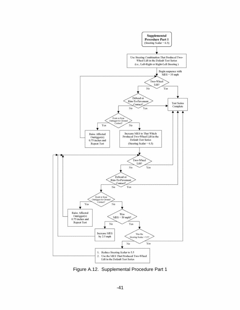
3.2.3.1 Supplemental Procedure Part 1
Following the tire scrub-in procedure outlined in Section 4.6, tests are performed with handwheel angles equal to efault)Fishhook(dδ , as explained in Section 3.2.2. The steering combination (i.e., either left-right or right-left) that produced two-wheel lift in the Default Test Series is used. The first test is to be performed at a MES of 35 mph. This test is performed to ensure any mold sheen remaining from the tire break-in procedure has been removed from the tires. The second test is to be performed at the MES at which two-wheel lift had been previously observed (i.e., with the previous tire set). If two-wheel lift is produced during the test performed with handwheel angles equal to efault)Fishhook(dδ , the tip-up will be reported in the vehicle's NCAP Rollover Resistance Rating and the test series is deemed complete. If two-wheel lift is not produced and the MES is 47.5 mph, the MES is increased to 50 mph. If two-wheel lift is produced during the test performed with MES equal to 50 mph, the tip-up will be reported in the vehicle's NCAP Rollover Resistance Rating and the test series is deemed complete.
If two-wheel lift is not produced at 50 mph with handwheel angles equal to
efault)Fishhook(dδ , tests are performed with steering angles calculated by multiplying overall ,30 g.δ by a steering scalar of 5.5.
overall ,3.0tal)(SupplemenFishhook 5.5 gδδ ×=

-21
After the application of the reduced scalar, a test is to be performed, using the same steering combination (i.e., either left-right or right-left), at the MES at which two-wheel lift had been observed in the Default Test Series. If two-wheel lift is produced during the test performed with handwheel angles equal to
( ) alSupplementFishhook δ , the tip-up will be reported in the vehicle's NCAP Rollover Resistance Rating and the test series is deemed complete. If two-wheel lift is not produced and the MES is 47.5 mph, the MES is increased to 50 mph. If two-wheel lift is produced during the test performed with MES equal to 50 mph, the tip-up will be reported in the vehicle's NCAP Rollover Resistance Rating and the test series is deemed complete. If two-wheel lift is not produced at 50 mph, the test series is deemed complete and no tip-up will be reported in the vehicle's NCAP Rollover Resistance Rating.
A test series is terminated if rim-to-pavement contact or tire debeading is observed during any Supplemental Procedure Part 1 test. The flowchart presented in Fig A.12 describes the sequence of events for the Supplemental Procedure Part 1.
3.2.3.2 Supplemental Procedure Part 2
If two-wheel lift is not produced during tests performed with the Default Procedure, the steering scalar is reduced from 6.5 to 5.5. Using the same tires used for tests performed with the Default Test Series, tests are performed with steering angles calculated by multiplying overall ,30 g.δ by a steering scalar of 5.5.
overall ,3.0tal)(SupplemenFishhook 5.5 gδδ ×=
For the sake of driver safety, the first test of the left-right sequence with the reduced steering scalar applied is to be performed at a MES of 45 mph. If this test does not produce two-wheel lift, the MES is increased to 47.5 mph. If the test with MES equal to 47.5 mph does not produce two-wheel lift, the MES is increased to 50 mph (the maximum MES used for Fishhook maneuver testing). If no two-wheel lift is observed during the left-right sequence, the right-left test sequence is initiated using the same process as the left-right sequence. If any

-22
test in the Supplemental Procedure Part 2 test series produces two-wheel lift, a new set of tires is installed on the vehicle, and the procedure described Section 3.2.3.3 is implemented.
A test series is terminated if rim-to-pavement contact or tire debeading is observed during any test performed with either test sequence. A test series is deemed complete if both test sequences within the series have been performed at the maximum maneuver entrance speed without two-wheel lift. The flowchart presented in Fig A.13 describes the sequence of events for the Supplemental Procedure Part 2.
3.2.3.3 Supplemental Procedure Part 3
Following the tire scrub-in procedure outlined in Section 4.6, two tests are performed with handwheel angles equal to ( ) alSupplementFishhook δ . The steering combination that produced two-wheel lift during Supplemental Procedure Part 2 testing is used (i.e., either left-right or right-left). The first test is to be performed at a MES of 35 mph. This test is performed to ensure any mold sheen remaining from the tire break-in procedure has been removed from the tires. The second test is to be performed at the MES that had produced two-wheel lift during Supplemental Procedure Part 2 testing (i.e., with the previous tire set). If two-wheel lift is produced during the test performed with handwheel angles equal to
( ) alSupplementFishhook δ , the tip-up will be reported in the vehicle's NCAP Rollover Resistance Rating and the test series is deemed complete. If two-wheel lift is not produced and the MES is 45 mph, the MES is increased to 47.5 mph. If two-wheel lift is not produced and the MES is 47.5 mph, the MES is increased to 50 mph. If two-wheel lift is produced during any test performed during Supplemental Procedure Part 3, the tip-up will be reported in the vehicle's NCAP Rollover Resistance Rating and the test series is deemed complete. If two-wheel lift is not produced during Supplemental Procedure Part 3, the test series is deemed complete and no tip-up will be reported in the vehicle's NCAP Rollover Resistance Rating.

-23
A test series is terminated if rim-to-pavement contact or tire debeading is observed during any Supplemental Procedure Part 3 test. The flowchart presented in Fig A.14 describes the sequence of events for the Supplemental Procedure Part 3.
3.2.4 Handwheel Inputs
3.2.4.1 Steering Rate
The handwheel rates of the initial steer and counter-steer steering ramps are always to be performed with nominal steering rates of 720 degrees per second, regardless of what steering scalar is used.
3.2.4.2 Dwell Time
The Fishhook maneuver is designed to maximize the roll motion of the test vehicle. When left-right steering is used, this is accomplished by:
1. Steering the vehicle with an input equal to ( ) DefaultFishhook δ or
( ) alSupplementFishhook δ
2. Waiting until the vehicle achieves maximum roll angle
3. Reversing the direction of steer
4. Steering the vehicle with an input equal to ( ) DefaultFishhook δ− or
( ) alSupplementFishhook δ−
When right-left steering is used, the sign conventions indicated in Steps 1 and 4 above are switched from positive to negative (i.e., for Step 1) or from negative to positive (i.e., for Step 4).
Dwell time is defined as the time from the completion of the initial steering ramp to the initiation of the steering reversal. A roll rate "Window Comparator" is

-24
used to determine when the vehicle has achieved maximum roll angle. Since the programmable steering machine used by NHTSA has a mechanical overshoot after completion of the initial steer, dwell time is not measured directly with handwheel angle data. Rather, two signals output from the steering machine are used: "Handwheel Start" and "Roll Flag".
3.2.4.2.1 Steering Machine Window Comparator
As indicated in Fig A.10, Fishhook maneuver steering reversals are commanded after the completion of the initial steering ramp and when the roll rate of the vehicle is very close to zero (because it is the derivative of roll angle, when roll rate is equal to zero at this point, roll angle is at its maximum). To minimize the likelihood of erroneous reversals, the reversals occur when the roll rate signal transmitted from a sensor positioned near the test vehicle's center of gravity enters the window comparator. The window comparator is defined as ±1.5 degrees per second, regardless of what steering scalar was used.
Examples: If an initial steer to the left is input, the reversal is initiated when the roll velocity of the vehicle is equal to 1.5 degrees per second. If an initial steer to the right is input, the reversal is initiated when the roll velocity of the vehicle is equal to -1.5 degrees per second.
3.2.4.2.2 Handwheel Command Flag
The programmable steering machine used by NHTSA outputs a "Handwheel Command Flag" signal based on the machine's internal clock. The output of the Handwheel Command Flag signal ranges from 0 to 10 volts, and is binary. The signal is high (10 volts) when the steering machine is in the process of executing a commanded input, or low (0 volts) when the machine is not in use or a pause is commanded during the execution of a commanded input, as shown in Fig A.10. When the pause ends, and execution of the commanded steering

-25
inputs are resumed, the Handwheel Command Flag signal is once again set high. In a Fishhook maneuver, the duration of the pause is the dwell time.
3.2.4.2.3 Roll Rate Flag
The "Roll Rate Flag" signal output by the programmable steering machine used by NHTSA is monitored. Like that of the Handwheel Command Flag channel, the Roll Rate Flag output ranges from 0 to 10 volts, and is binary. The signal is high (10 volts) when the roll rate of the test vehicle is within the window comparator or low (0 volts) when roll rate is outside the window comparator, as shown in Fig A.10.
Fishhook maneuver steering reversals are to be initiated by the steering machine within 10 milliseconds of the roll rate entering the window comparator. Initiation of the steering reversal is defined as the instant the steering machine sets the Roll Rate Flag signal high.
Note: After completion of the initial steer, the instants that the steering machine sets the Roll Rate Flag and Handwheel Command Flag signals high should coincide.
3.2.4.3 Excessive Steering
In some cases, the magnitude of ( ) DefaultFishhook δ used during the Default Procedure may be so great that the vehicle reaches maximum roll angle before completion of the initial steer. This is defined as excessive steering; i.e., the vehicle cannot respond to the entire commanded steering input.
Excessive steering is also said to occur if the dwell time of a Fishhook test performed with the Default Procedure results in a dwell time less than 80 milliseconds. The mechanical overshoot of the steering machine that occurs after completion of the initial steer can prohibit the machine from accurately executing dwell times less than approximately 80 milliseconds. In such cases,

-26
the effect of the overshoot is that the actual dwell time is equal to zero (an immediate steering reversal).
NHTSA's experience with the Fishhook maneuver has demonstrated the effect of excessive steering on dynamic rollover resistance is vehicle-dependent. While it may not allow the roll motion of some test vehicles to be maximized, excessive steering has been shown to contribute to an increased tip-up propensity in others. For this reason, a test sequence for which excessive steering is observed should not be terminated. Testing should proceed as outlined in Section 3.2.2, Default Procedure. If two-wheel lift is not observed during either Default Procedure test sequence, the Supplemental Procedure beginning at Part 2, described in Section 3.2.3.2, is performed.
4.0 ITEMS PERTAINING TO TEST CONDUCT
4.1 Definition of Two-Wheel Lift
Two-wheel lift is defined as the occurrence of at least two inches of simultaneous lift of the inside wheels from the test surface. NHTSA does not consider two-wheel lift less than two inches when calculating a vehicle's NCAP rollover resistance rating. Two-wheel lift great enough to require outriggers to suppress further roll motion is to be reported simply as "two-wheel lift" as long as at least two inches of simultaneous two-wheel lift occurs before outrigger contact with the ground is made.
4.2 Vehicle Test Configurations
1. NHTSA will provide the contractor a list of vehicles. In general: For SUVs, the 4x2 version will be tested using the Fishhook maneuver test. If the 4x2 does not experience a two wheel lift a “no tip” will be used for the 4x4 version as well. If the 4x2 version does experience a two wheel tip, the 4x4 version will be tested using the Fishhook maneuver test.

-27
2. For pickups, the 4x4 version will be tested to the Fishhook maneuver test. If the 4x4 does not experience a two wheel lift a “no tip” will be used for the 4x2 version. If the 4x4 does experience a two wheel tip the 4x2 version will be tested using the Fishhook maneuver test.
3. For vans and passenger cars, specific versions of the vehicle will be determined by NHTSA.
4.2.1 Load Configurations
All vehicles are to be evaluated with one of the two load configurations previously defined in Section 2.1.
4.2.2 Fuel Tank Loading
Prior to beginning a Slowly Increasing Steer or Fishhook maneuver test series, the fuel tank of the vehicle is to be completely filled at the beginning of testing and may not be less than 75% of capacity during any part of the testing. This criterion is in agreement with that defined in FMVSS 135.
4.2.3 Stability Control System
If equipped, vehicles are tested with stability control systems active. Stability control is not to be deactivated for any Slowly Increasing Steer or Fishhook maneuver.
4.3 Road Test Surface
Tests are conducted on a dry, uniform, solid-paved surface. Surfaces with irregularities, such as dips and large cracks, are unsuitable, as they may confound test results.
4.3.1 Pavement Friction

-28
All maneuvers are to be performed on a dry, high-mu road test surface.
Unless otherwise specified, the road test surface produces a peak friction coefficient (PFC) of approximately 0.9 when measured using an American Society for Testing and Materials (ASTM) E1136 standard reference test tire, in accordance with ASTM Method E 1337-90, at a speed of 64.4 km/h (40 mph), without water delivery. This criterion is in agreement with that defined in FMVSS 135.
4.3.2 Slope
The test surface has a consistent slope between level and 2%. All tests are to be initiated in the direction of positive slope (uphill).
4.4 Ambient Conditions
4.4.1 Ambient Temperature
The ambient temperature shall be between 0° C (32° F) and 40° C (104° F). This criterion is in agreement with that defined in FMVSS 135.
4.4.2 Wind Speed
The maximum wind speed shall be no greater than 10 m/s (22 mph).
4.5 Calibration Data
It is strongly recommended that calibration data be collected prior to tests of each configuration to assist in resolving uncertain test data. NHTSA typically records the following data at the beginning of each test day for each test vehicle configuration.
– The distance measured by the speed sensor along a straight line between the end points of a surveyed linear roadway standard of

-29
1000 feet or more (observed and recorded manually from the speed sensor display).
– Five to fifteen seconds of data from all instrument channels as the configured and prepared test vehicle is driven in a straight line on a level, uniform, solid-paved road surface at 60 mph.
4.6 Tire Break-In Procedure
Prior to each test series, the tires must be "scrubbed in" to wear away mold sheen and be brought up to operating temperature. Test vehicles are to be driven around a circle 100 feet in diameter at a speed that produces a lateral acceleration of approximately 0.5 to 0.6 g. Using this circle, three clockwise laps are to be followed by three counterclockwise laps. Once the six laps of the circle are complete, the driver is to input, sinusoidal steering at a frequency of 1 Hz and a handwheel amplitude ( )ssδ corresponding to 0.5-0.6 g for 10 cycles while maintaining a vehicle speed of 35 mph. A total of four passes using sinusoidal steering are to be used. The handwheel magnitude of the final cycle of the final pass is to be twice that of ssδ . These four sinusoid passes typically require an area similar in size to that required by the Fishhook maneuver. The steering machine should be programmed to execute the sinusoids. There should be only a minimal delay between the completion of the tire break-in and the start of a test series to allow for the collection of a static data file, steering machine and data acquisition system adjustment, and final driver briefing.
4.7 Static Datums
At the completion of the tire break-in procedure and before the start of a test series, fifteen seconds of data are collected from all instrument channels with the test vehicle at rest, the engine running, the transmission in "Park" (automatic transmission) or in neutral with the parking brake applied (manual transmission), and the front of the test vehicle facing in the direction of positive gradient (uphill) on the test surface. The static data files are used in post processing establish datums for each instrument channel.

-30
4.8 Vehicle Gear Selection
All tests are performed with automatic transmissions in "Drive" or with manual transmissions in the highest gear capable of sustaining the desired test speed (Slowly Increasing Steer) or Maneuver Entrance Speed (Fishhook), with one exception:
Slowly Increasing Steer tests may be performed with automatic transmissions in lower gears if 50 mph cannot be maintained in "Drive" and the gear selection does not result in engine overspeeding. In some cases, 50 mph cannot be maintained through to the end of the steering schedule regardless of the gear selection due to low engine power or chassis responses that result in the loss of traction or spin out. It has been NHTSA's experience, however, that maximum lateral acceleration is generally achieved well before the maneuver's maximum handwheel angle is attained.
Manual transmission clutches are to remain engaged during all maneuvers.
4.9 Outrigger Adjustment
The initial clearance between the road surface and the bottom of the NHTSA outrigger skid pads is approximately 14 inches for the "standard" outriggers and approximately 12 inches for the "short" outriggers with the test vehicle at rest on a level surface. Note that the Multi-Passenger Configuration may compress the suspension more than the Nominal Load Configuration (reducing outrigger clearance). As such, outrigger height adjustment may be required when transitioning from one load configuration to the next.
Outrigger height adjustment may be required during a test series. If an outrigger skid pad contacts the road surface during a test run wherein there is no two-wheel lift, the outrigger at the effected end of the vehicle is raised 0.75 inches and the test run is repeated at the same maneuver entrance speed. If

-31
both outriggers make contact with the test surface during at test run wherein there is no two-wheel lift, both outriggers are raised 0.75 inches and the test run is repeated at the same maneuver entrance speed.
4.10 Videotape Documentation
It is recommended that all test runs be documented on videotape. NHTSA videotapes Slowly Increasing Steer tests from a viewpoint several hundred feet outside the circular path of the test vehicle. Fishhook maneuver tests are videotaped from a viewpoint that facilitates observation of the inboard side of the vehicle so as to best record instances of two-wheel lift. For both maneuvers, it is recommended the zoom of the camera be adjusted during each test such that the vehicle fills the view frame to the greatest extent possible.
4.11 Summary of Tests To Be Performed For Each Vehicle
For each test vehicle, testing will be performed according to the following plan:
1. Installation of new tires
2. Tire break-in
3. Slowly Increasing Steer Maneuver test series in the Nominal Load or Multi-Passenger Configuration
4. Tire change
5. Tire break-in
6. NHTSA Fishhook maneuver test series in the Nominal Load or Multi-Passenger Configuration with additional tire changes and break-ins as indicated in the maneuver protocol

-32
4.12 Summary of Metrics Measured For Each Vehicle
1. Overall handwheel position at 0.3 g in the Nominal Load Configuration
2. Two-Wheel Lift in NHTSA Fishhook maneuver in Nominal Load or Multi-Passenger Configuration (Yes/No)
3. Rim-to-Pavement Contact or Tire Debeading in Nominal Load Nominal Load or Multi-Passenger Configuration (Yes/No)
4.13 Post Processing
Data are filtered in post processing with a 6-Hz 12-pole, 2-pass, phaseless digital Butterworth filter. All accelerations are corrected for CG displacement (see Section 2.5.1.3). Laser height measurements are filtered with a one-pass 200 ms running average technique.
Post processing also includes roll effects correction for lateral acceleration as follows.
where,
is the corrected lateral acceleration (i.e., the vehicle's lateral acceleration in a plane horizontal to the test surface)
is the measured lateral acceleration in the vehicle reference frame
zma is the measured vertical acceleration in the vehicle reference frame
Φ−Φ= sincos zmymyc aaa
yca
yma

-33
Φ is the vehicle's roll angle
Note: The z-axis sign convention is positive in the downward direction for both the vehicle and test surface reference frames.
5.0 REFERENCES
1. Forkenbrock, G.J., Garrott, W.R, Heitz, Mark, O'Harra, Brian C., "A Comprehensive Experimental Examination of Test Maneuvers That May Induce On-Road, Untripped Light Vehicle Rollover - Phase IV of NHTSA's Light Vehicle Rollover Research Program," NHTSA Technical Report, DOT HS 809 513, October 2002.
2. Forkenbrock, G.J., O'Harra, Brian C., Elsasser, Devin, "An Experimental Examination of 26 Light Vehicles Using Test Maneuvers That May Induce On-Road, Untripped Light Vehicle Rollover - Phase VI of NHTSA's Light Vehicle Rollover Research Program," NHTSA Technical Report, DOT HS 809 547, 2003.
3. NHTSA, "NHTSA's Experience With Outriggers Used For Testing Light Vehicle - A Brief Summary," Docket No. NHTSA-2001-9663, January 2003.
4. NHTSA, "NHTSA's Set-Up Procedures for Wheel Lift Sensors - A Brief Overview," Docket No NHTSA-2001-9663, April 2003.
5. SAE J266, Surface Vehicle Recommended Practice, "Steady-State Directional Control Test Procedures For Passenger Cars and Light Trucks," 1996.

-34
Figure A.1. Equipment Location

-35
Figure A.2. Water dummy placement for vehicles with three or more designated rear seating positions, excluding pick-up trucks. Note: A water dummy is placed in the third seating row, only when the second seating row is limited to two designated seating positions.
Figure A.3. Water dummy placement for vehicles with two designated rear seating positions, excluding pick-up trucks.

-36
Figure A.4 Water dummy placement for pick-up trucks with no designated rear seating positions. Note: A water dummy is placed in a simulated third seating row only when the inside width of the cargo bed prevents the placement of three dummies side by side in the simulated second row.
Figure A.5 Water Dummy Placement - Pick-up trucks with two or more designated rear seating positions. Note: A water dummy is placed in a simulated third seating row only when the second seating row is limited to two designated seating positions.

-37
Figure A.6. Slowly Increasing Steer Maneuver Description (Option #1)
Figure A.7. Slowly Increasing Steer Maneuver Description (Option #2)

-38
Figure A.8. Sample Handwheel Angle and Lateral Acceleration Data (Option #1). The linear range used to define the lateral acceleration regression line is highlighted.
Figure A.9. Sample Handwheel Angle and Lateral Acceleration Data (Option #2). The linear range used to define the lateral acceleration regression line is highlighted.

-39
A = SS * Handwheel Position at 0.3 g SS = Steering scalar T1 = Time from completion of first Handwheel ramp to ±1.5 deg/sec roll velocity T2 = 3 second pause T3 = 2 seconds B = 1.5 deg/sec window comparator threshold Initial steer and counter steer performed at 720 deg/sec
Figure A.10. NHTSA Fishhook Maneuver Description

-40
Figure A.11. Default Test Procedure
-41
Figure A.12. Supplemental Procedure Part 1

-42
Figure A.13. Supplemental Procedure Part 2

-43
Figure A.14. Supplemental Procedure Part 3