fitting instructions for r1 2000d1l4i7f87txqmq.cloudfront.net/installation instructions/r&g...
TRANSCRIPT

R&G Racing
Unit 1, Shelley’s Lane, East Worldham, Alton, Hampshire, GU34 3AQ
Tel: +44 (0)1420 89007 Fax: +44 (0)1420 87301 www.rg-racing.com Email: [email protected]
FITTING INSTRUCTIONS FOR LP0185BK LICENCE PLATE BRACKET
BMW S1000XR ’15-
THIS KIT CONTAINS THE ITEMS PICTURED AND LABELLED BELOW.
DO NOT PROCEED UNTIL YOU ARE SURE ALL PARTS ARE PRESENT.
Please note that the way the kit is packed does not necessarily represent the way of mounting to the bike.
THE PARTS SHOWN MAY BE REPRESENTATIVE ONLY (FOR CLARITY OF INSTRUCTIONS ONLY).
1 12
13
3 16
1
3 3
8
10 2
9
3
4
11
12
3
4
5 6
6
7

R&G Racing
Unit 1, Shelley’s Lane, East Worldham, Alton, Hampshire, GU34 3AQ
Tel: +44 (0)1420 89007 Fax: +44 (0)1420 87301 www.rg-racing.com Email: [email protected]
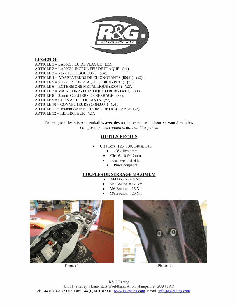
LEGEND ITEM 1 = LA0003 TAIL LIGHT (x1).
ITEM 2 = LA0003 TAIL LIGHT SHROUD (x1).
ITEM 3 = M6 x 16mm LONG BUTTON HEAD BOLTS (x4).
ITEM 4 = INDICATOR ADAPTORS (I0041) (x2).
ITEM 5 = LICENCE PLATE BRACKET (TB0185 Part 1) (x1).
ITEM 6 = METAL EXTENSIONS (E0059) (x2).
ITEM 7 = MAIN PLASTIC BODY (TB0185 Part 2) (x1).
ITEM 8 = 2.5mm CABLE TIES (x3).
ITEM 9 = SELF ADHESIVE CABLE CLIPS (x2).
ITEM 10 = BULLET CONNECTORS (CON0004) (x4).
ITEM 11 = 150mm LENGTH OF HEATSHRINK (x3).
ITEM 12 = REFLECTOR (x1).
Please note that in cases where kits are packed with rubber washers holding the components onto
the bolt – the rubber washers should be thrown away!
TOOLS REQUIRED
Set of Torx bits to include T25, T30, T40 & T45 sizes.
5mm allen key or socket.
6, 10 & 12mm spanners or sockets.
Thin flat-head screwdriver.
Cable cutters.
MAXIMUM TORQUE SETTINGS M4 Bolt = 8 Nm
M5 Bolt = 12 Nm
M6 Bolt = 15 Nm
M8 Bolt = 20 Nm
Picture 1 Picture 2

R&G Racing
Unit 1, Shelley’s Lane, East Worldham, Alton, Hampshire, GU34 3AQ
Tel: +44 (0)1420 89007 Fax: +44 (0)1420 87301 www.rg-racing.com Email: [email protected]
Picture 3
Picture 4
Picture 5
Picture 6
Picture 7 Picture 8

R&G Racing
Unit 1, Shelley’s Lane, East Worldham, Alton, Hampshire, GU34 3AQ
Tel: +44 (0)1420 89007 Fax: +44 (0)1420 87301 www.rg-racing.com Email: [email protected]
Picture 9 Picture 10
Picture 11
Picture 12
Picture 13 Picture 14
R&G Racing
Unit 1, Shelley’s Lane, East Worldham, Alton, Hampshire, GU34 3AQ
Tel: +44 (0)1420 89007 Fax: +44 (0)1420 87301 www.rg-racing.com Email: [email protected]
Picture 15 Picture 16
Picture 17
Picture 18
Picture 19 Picture 20

R&G Racing
Unit 1, Shelley’s Lane, East Worldham, Alton, Hampshire, GU34 3AQ
Tel: +44 (0)1420 89007 Fax: +44 (0)1420 87301 www.rg-racing.com Email: [email protected]
Picture 21
Picture 22
Picture 23
Picture 24
Picture 25
Picture 26

R&G Racing
Unit 1, Shelley’s Lane, East Worldham, Alton, Hampshire, GU34 3AQ
Tel: +44 (0)1420 89007 Fax: +44 (0)1420 87301 www.rg-racing.com Email: [email protected]
Picture 27
Picture 28
Picture 29
Picture 30
Picture 31 Picture 32

R&G Racing
Unit 1, Shelley’s Lane, East Worldham, Alton, Hampshire, GU34 3AQ
Tel: +44 (0)1420 89007 Fax: +44 (0)1420 87301 www.rg-racing.com Email: [email protected]
Picture 33
Picture 34
Picture 35
Picture 36
Picture 37
Picture 38

R&G Racing
Unit 1, Shelley’s Lane, East Worldham, Alton, Hampshire, GU34 3AQ
Tel: +44 (0)1420 89007 Fax: +44 (0)1420 87301 www.rg-racing.com Email: [email protected]
Picture 39
Picture40
Picture 41
Picture 42
Picture 43
Picture 44

R&G Racing
Unit 1, Shelley’s Lane, East Worldham, Alton, Hampshire, GU34 3AQ
Tel: +44 (0)1420 89007 Fax: +44 (0)1420 87301 www.rg-racing.com Email: [email protected]
Picture 45
Picture 46
Picture 47
Picture 48
Picture 49
Picture 50

R&G Racing
Unit 1, Shelley’s Lane, East Worldham, Alton, Hampshire, GU34 3AQ
Tel: +44 (0)1420 89007 Fax: +44 (0)1420 87301 www.rg-racing.com Email: [email protected]
Picture 51
Picture 52
Picture 53
Picture 54
FITTING INSTRUCTIONS
To fit the R&G tail tidy, remove the seat using the key at the rear of the bike, as shown in picture
1.
Remove the four Torx bolts that secure the plastic mudguard in place, as shown in pictures 2 & 3.
Gently pull this forward to remove it from the rubber mounts at the rear and clear of the bike, as
shown in picture 4.
If the pannier rack is fitted, remove the two luggage mounting points, one on either side of the
bike, as shown in picture 5.
This now allows access to the rack mounting bolts. Remove all of these, two on either side of the
bike, and remove the pannier rack, as shown in pictures 6 & 7.
Remove the final two bolts that secure the aluminium luggage frame in place and remove from the
bike, as shown in picture 8.
Within the rear subframe, there is a large plastic tray which most of the bodywork attaches too, as
shown in picture 9. We advise to check this tray and all the panels are fitted centrally to ensure the

R&G Racing
Unit 1, Shelley’s Lane, East Worldham, Alton, Hampshire, GU34 3AQ
Tel: +44 (0)1420 89007 Fax: +44 (0)1420 87301 www.rg-racing.com Email: [email protected]
R&G Tail Tidy fits correctly and has equal panel gaps all around. It is suggested to loosen these
bolts whilst fitting the tail tidy and to re-tighten when all the parts are satisfactorily fitted.
Remove the Torx bolt that connects the two plastic surround panels to the OEM licence plate
hanger, as shown in picture 10.
These parts can now be un-clipped from each other and spread apart, as shown in picture 11.
Remove the four push rivets, shown in pictures 12 & 13, by pushing the centre through. These
plastics pins will push through into the OEM licence plate hanger. With the pins out, remove the
outer section of the push rivet.
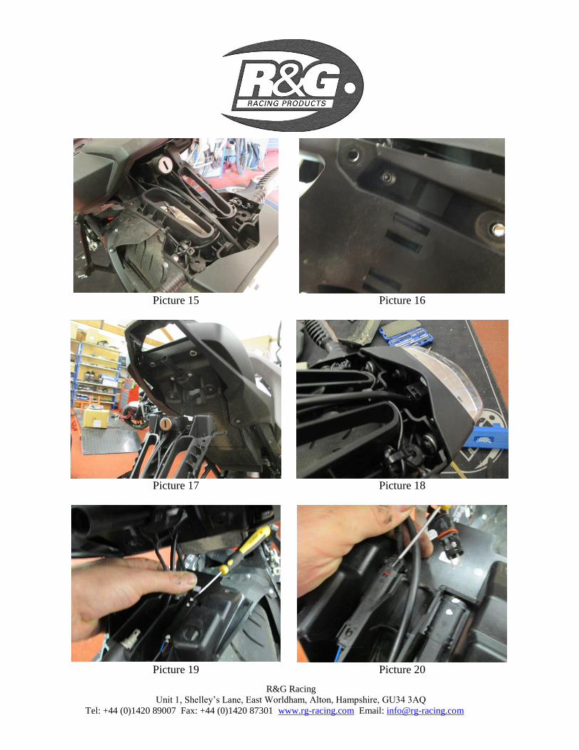
The top half of the hanger can now be removed by lifting the rear upward and then sliding back to
remove it from the lock barrel, as shown in pictures 14 & 15.
On the underside of the OEM licence plate hanger, remove the two Torx bolts, as shown in picture
16.
The OEM licence plate hanger can now be gently pulled rearward to un-locate the lock and then
dropped clear of the rear of the bike, as shown in picture 17.
Disconnect the wiring connector for the rear light, as shown in picture 18, along with the cable ties
that bunch the wires together.
Using a very small screwdriver, disconnect the indicator connectors, as shown in pictures 19 & 20.
It is a good idea to mark the matching connectors on one side, to ensure the correct re-fitment.
The wiring can now be fed through and the OEM licence plate hanger removed from the bike, as
shown in picture 21.
On the bike, pull the wiring up through the hole on the underside of the tail so that they sit within
the plastic tray, as shown in picture 22.
On the OEM hanger, use a small screwdriver to firstly remove the indicator connector from the
mount and then remove the mount from the hanger by inserting the thin screwdriver under the back
and pushing the prong to one side, as shown in pictures 23 & 24. Do this for both connectors &
mounts.
Remove the key lock barrel from the plastic, by pushing down on the exposed tab and sliding out,
as shown in picture 25.
To fit the R&G Tail Tidy, take the R&G tail light (item 1 – LA0003) and fit the plastic light shroud
(item 2), as shown in picture 26.
Locate this assembly onto the licence plate bracket (item 5 – TB0185 Part 1) and tighten the nuts
on the rear, as shown in pictures 27 & 28.
If fitting R&G Mini Indicators
Take the mini indicator and feed the wires though the hole of one of the indicator adaptors (item 4
– I0041), as shown in picture 29.
Fit one length of heatshrink supplied (item 11) to protect the indicator wiring before feeding the
wires through the indicator mounting hole on the tail tidy, as shown in picture 30. Feed the flanged
nut over the wiring and tighten onto the threaded boss of the indicator.
Take the main plastic body (item 7 – TB0185 Part 2) and feed all the wiring through the hole
below the hole for the lock, as shown in pictures 31 & 32.
To fit the R&G Mini Indicators, the OEM indicator wiring will need to be cut and shut in order to
connect the indicators. To do this, cut through the rear indicator wires about 50mm from the
connector. Strip the ends of the two wires on the connector end and fit the bullet connectors
supplied (item 10 – CON0004) to the two wires for the indicators in order to match them to the
bullet connectors on the R&G Mini Indicators.
If fitting R&G Aero Indicators with LED’s the yellow wire on the Aero Indicators connects with the
black/red or black/blue wire on either indicator and the black wire on the Mini Indicators connects

R&G Racing
Unit 1, Shelley’s Lane, East Worldham, Alton, Hampshire, GU34 3AQ
Tel: +44 (0)1420 89007 Fax: +44 (0)1420 87301 www.rg-racing.com Email: [email protected]
with the brown wire on the OEM wiring. 1x set of RGR0002 resistors (available separately) are
required to achieve the correct flash rate.
If fitting R&G Mini Indicators with bulbs, the black wire on the Mini Indicators connects with the
brown wire on either indicator and the black/white wire on the Mini Indicators connects with the
black/red or black/blue wire on the OEM wiring.
If fitting R&G Mini Indicators with bulbs, the black wire on the Mini Indicators connects with the
brown wire on either indicator and the black/white wire on the Mini Indicators connects with the
black/red or black/blue wire on the OEM wiring. 1x set of RGR0001 resistors (available
separately) are required to achieve the correct flash rate.
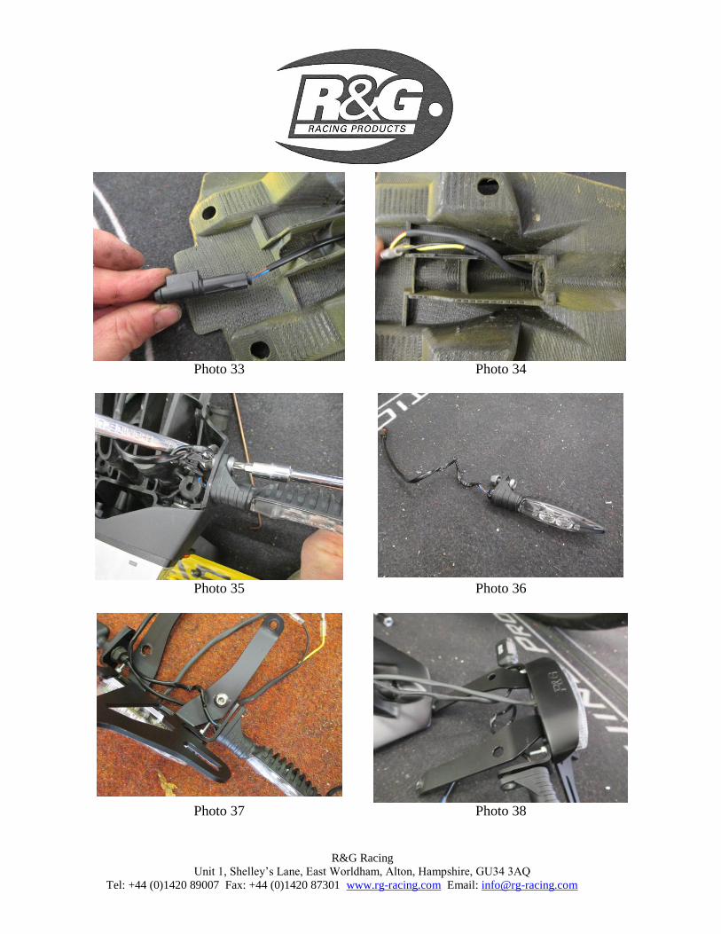
Re-fit the OEM plastic connector mount to the connectors and route the wiring as shown in
pictures 33 & 34. It is advised to route the wiring along the side of the central rib, but there is
room for the wiring down the centre.
If fitting OEM Indicators
Remove the OEM indicators from the OEM licence plate hanger using a 10mm spanner and Torx
bit, as shown in picture 35 & 36.
Fit the indicator to the R&G tail tidy assembly by feeding the wiring through the larger hole on the
indicator tab of the main bracket and then insert the indicator, before rotating to hold in place, as
shown in picture 37. Do not re-fit the nut & Torx bolt at this point as it prevents the fit of the
mounting bolt.
Take the main plastic body (item 7 – TB0185 Part 2) and feed all the wiring through the hole
below the hole for the lock, as shown in pictures 38 & 39.
Re-fit the OEM plastic connector mount to the connectors and route the wiring as shown in
pictures 40 & 41. It is advised to route the wiring along the side of the central rib, but there is
room for the wiring down the centre.
Remove the metal J-Clip from the OEM plastic cover and re-fit this to the main plastic body in the
same position, as shown in pictures 42 & 43.
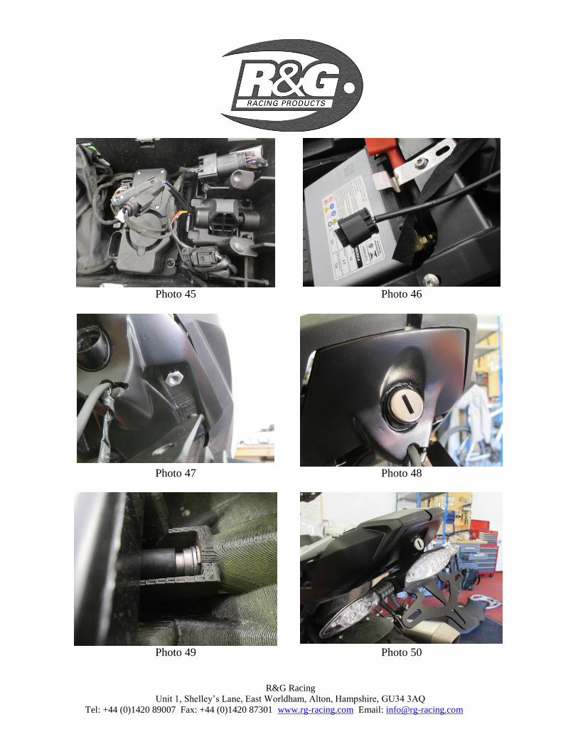
With the wiring now located through the main plastic body, this assembly needs to be held up to
the bike and the have the wiring fed through the hole in the undertray, to allow the wiring to
accessed from the top of the tail unit, as shown in pictures 44 & 45. Pull as much of the wiring
through as possible and re-connect to the OEM connectors on the loom.
To connect the new tail light to the main loom, the wires need to be “cut and shut”. To do this, cut
the connector off the OEM wiring and fit bullet connectors to all three of the wires. Fit the opposite
connectors to the tail light wiring and connect the wiring as follows: OEM brown to black, OEM
red/grey to yellow & OEM black/grey to red.
It is a good idea to check for the correct operation of the lights at this stage.
Take the two metal extensions (item 6 – E0059) and screw these through the two rearward slots on
the main plastic body and into the threaded bosses on the underside of the subframe, as shown in
picture 47. Ensure the stepped boss on the extension sits within the slot and the front holes align
before using a 12mm socket to tighten the extensions. Whilst doing this, please check to make sure
no wiring gets trapped or pinched between the main plastic body and underside of the tail.
Fit the key lock barrel in the same way that it was removed, ensuring that the final tab on the back
expands out and locks on the plastic, as shown in pictures 48 & 49.The lock should now operate
correctly and it’s a good idea to check at this stage.
Now the licence plate bracket can be offered into position against the plastic body. Whilst doing
this, pull through any loose wiring from above to prevent an excess on the outside of the bike, as
shown in picture 50.

R&G Racing
Unit 1, Shelley’s Lane, East Worldham, Alton, Hampshire, GU34 3AQ
Tel: +44 (0)1420 89007 Fax: +44 (0)1420 87301 www.rg-racing.com Email: [email protected]
Fit the four M6 x 16mm long button head bolts (item 3) through the four mounting holes on the
licence plate bracket and into the threaded extensions on the rear two holes and through the plastic
and into the threaded bosses on the front, as shown in pictures 51 & 52. Whilst tightening the front
two bolts, ensure the swaged spacer on the licence plate bracket locates correctly through the slot
and tightens up correctly. At this point, if the plastic tray and bodywork does not line up very well,
it can be re-positioned whilst the bolts are still loose. Once satisfied with the fit, tighten all bolts,
including those on the plastic tray & bodywork.
Re-fit the Torx bolt that secures the plastic surround to the top of the main plastic body using the J-
Clip, as shown in picture 53. Again, this can be adjusted sideways to get a perfect fit.
If re-fitting the OEM indicators, the nut & Torx bolt to secure them in place can be re-fitted and
tightened on both indicators, as shown in picture 54.
Re-fit the aluminium luggage frame and tighten the two Torx bolts to secure in place.
Re-fit the pannier rack using the four Torx bolts along with the additional two mounts luggage
mounts fitted after.
Check that all bodywork mounting bolts have been re-tightened and that the tail tidy is securely
fixed in place.
Re-fit the licence plate (it may require drilling).
Depending on local laws, attach enclosed reflector in an appropriate location.
Test the license plate illuminator and all lights before riding.
ISSUE 1 09/10/2015 (AR)
Digital copies of these instructions are available to download from www.rg-racing.com
CONSUMER NOTICE
The catalogue description and any exhibition of samples are only broad indications of the Products and R&G may make design
changes which do not diminish their performance or visual appeal and supplying them in such state shall conform to the order. The Buyer acknowledges no representation or warranty (other than as to title) has been given or will apply to the Products other than those
in R&G’s order or confirmation and the Buyer confirms it has chosen the Products as being of merchantable quality and suitable for its
particular purposes. Where R&G fits the Products or undertakes other services it shall exercise reasonable skill and care and rectify any fault free of charge unless the workmanship has been disturbed. The Buyer is responsible for ensuring that the warranty on the
motorcycle is not affected by the fitting of the Products. On return of any defective Products R&G shall at its option either supply a
replacement or refund the purchase money but shall not be liable if the Products have been modified or used or maintained otherwise than in accordance with R&G’s or manufacturer’s instructions and good engineering practice or if the defect arises from accident or
neglect. Other than identified above and subject to R&G not limiting its liability for causing death and personal injury, it shall not be
liable for indirect or consequential loss and otherwise its liability shall be limited to the amounts paid by the Buyer for the Products or the fitting or service concerned. These terms do not affect the Buyer’s statutory rights.
R&G RACING RETURNS POLICY (NON-FAULTY GOODS)
Returns must be pre-authorised (if not pre-authorised the return will be rejected). Goods may only be returned direct to us if they were purchased direct from us (customer must prove if necessary). Otherwise to be returned to original vendor. Goods must be in re-sellable
condition, in the opinion of R&G Racing. All returns are subject to a 25% restocking and handling fee (25% of the gross value exc.
P&P – at the prevailing price at time of purchase). The customer must pay any and all carriage charges. No returns of discontinued products, unless within 14 days of purchase. This policy does not affect your statutory rights and does not refer to faulty goods.

R&G Racing
Unit 1, Shelley’s Lane, East Worldham, Alton, Hampshire, GU34 3AQ
Tel: +44 (0)1420 89007 Fax: +44 (0)1420 87301 www.rg-racing.com Email: [email protected]
INSTRUCTIONS DE MONTAGE POUR LP0185BK SUPPORT DE PLAQUE
BMW S1000XR ’15-
Assurez vous que toutes les pièces soient présentes avant de procéder au montage.
La façon dont le kit est emballé ne correspond pas forcément à la façon de monter les pièces sur la moto.
LES PIECES PRESENTEES PEUVENT N’ETRE QUE REPRESENTATIVES, AFIN DE FACILITER ET CLARIFIER LES INSTRUCTIONS
DE MONTAGE.
1 12
13
3 16
1
3 3
8
10 2
9
3
4
11
12
3
4
5 6
6
R&G Racing
Unit 1, Shelley’s Lane, East Worldham, Alton, Hampshire, GU34 3AQ
Tel: +44 (0)1420 89007 Fax: +44 (0)1420 87301 www.rg-racing.com Email: [email protected]
LEGENDE ARTICLE 1 = LA0003 FEU DE PLAQUE (x1).
ARTICLE 2 = LA0003 LINCEUL FEU DE PLAQUE (x1).
ARTICLE 3 = M6 x 16mm BOULONS (x4).
ARTICLE 4 = ADAPTATEURS DE CLIGNOTANTS (I0041) (x2).
ARTICLE 5 = SUPPORT DE PLAQUE (TB0185 Part 1) (x1).
ARTICLE 6 = EXTENSIONS METALLIQUE (E0059) (x2).
ARTICLE 7 = MAIN CORPS PLASTIQUE (TB0185 Part 2) (x1).
ARTICLE 8 = 2.5mm COLLIERS DE SERRAGE (x3).
ARTICLE 9 = CLIPS AUTOCOLLANTS (x2).
ARTICLE 10 = CONNECTEURS (CON0004) (x4).
ARTICLE 11 = 150mm GAINE THERMO RETRACTABLE (x3).
ARTICLE 12 = REFLECTEUR (x1).
Notez que si les kits sont emballés avec des rondelles en caoutchouc servant à tenir les
composants, ces rondelles doivent être jetées.
OUTILS REQUIS
Clés Torx T25, T30, T40 & T45.
Clé Allen 5mm.
Clés 6, 10 & 12mm.
Tournevis plat et fin.
Pince coupante.
COUPLES DE SERRAGE MAXIMUM M4 Boulon = 8 Nm
M5 Boulon = 12 Nm
M6 Boulon = 15 Nm
M8 Boulon = 20 Nm
Photo 1 Photo 2

R&G Racing
Unit 1, Shelley’s Lane, East Worldham, Alton, Hampshire, GU34 3AQ
Tel: +44 (0)1420 89007 Fax: +44 (0)1420 87301 www.rg-racing.com Email: [email protected]
Photo 3
Photo 4
Photo 5
Photo 6
Photo 7 Photo 8

R&G Racing
Unit 1, Shelley’s Lane, East Worldham, Alton, Hampshire, GU34 3AQ
Tel: +44 (0)1420 89007 Fax: +44 (0)1420 87301 www.rg-racing.com Email: [email protected]
Photo 9 Photo 10
Photo 11
Photo 12
Photo 13 Photo 14

R&G Racing
Unit 1, Shelley’s Lane, East Worldham, Alton, Hampshire, GU34 3AQ
Tel: +44 (0)1420 89007 Fax: +44 (0)1420 87301 www.rg-racing.com Email: [email protected]
Photo 15 Photo 16
Photo 17
Photo 18
Photo 19 Photo 20

R&G Racing
Unit 1, Shelley’s Lane, East Worldham, Alton, Hampshire, GU34 3AQ
Tel: +44 (0)1420 89007 Fax: +44 (0)1420 87301 www.rg-racing.com Email: [email protected]
Photo 21
Photo 22
Photo 23
Photo 24
Photo 25
Photo 26

R&G Racing
Unit 1, Shelley’s Lane, East Worldham, Alton, Hampshire, GU34 3AQ
Tel: +44 (0)1420 89007 Fax: +44 (0)1420 87301 www.rg-racing.com Email: [email protected]
Photo 27
Photo 28
Photo 29
Photo 30
Photo 31 Photo 32
R&G Racing
Unit 1, Shelley’s Lane, East Worldham, Alton, Hampshire, GU34 3AQ
Tel: +44 (0)1420 89007 Fax: +44 (0)1420 87301 www.rg-racing.com Email: [email protected]
Photo 33
Photo 34
Photo 35
Photo 36
Photo 37
Photo 38

R&G Racing
Unit 1, Shelley’s Lane, East Worldham, Alton, Hampshire, GU34 3AQ
Tel: +44 (0)1420 89007 Fax: +44 (0)1420 87301 www.rg-racing.com Email: [email protected]
Photo 39
Photo40
Photo 41
Photo 42
Photo 43
Photo 44
R&G Racing
Unit 1, Shelley’s Lane, East Worldham, Alton, Hampshire, GU34 3AQ
Tel: +44 (0)1420 89007 Fax: +44 (0)1420 87301 www.rg-racing.com Email: [email protected]
Photo 45
Photo 46
Photo 47
Photo 48
Photo 49
Photo 50

R&G Racing
Unit 1, Shelley’s Lane, East Worldham, Alton, Hampshire, GU34 3AQ
Tel: +44 (0)1420 89007 Fax: +44 (0)1420 87301 www.rg-racing.com Email: [email protected]
Photo 51
Photo 52
Photo 53
Photo 54
INSTRUCTIONS DE MONTAGE
Pour monter la queue de support plaque R&G, enlever le siège en utilisant la clé située à l’arrière
de la moto, voir photo 1.
Enlever les 4 boulons Torx qui fixent le garde boue plastique en place, voir photos 2 & 3.
Tirez le doucement vers l’avant pour l’enlever de ces supports arrière puis enlevez le de la moto,
voir photo 4.
Si le porte bagage est installé, enlevez ses 2 points de support, un de chaque coté de la moto, voir
photo 5.
Cela permet à présent d’accéder aux boulons de montage du porte bagage. Enlevez les tous, deux
de chaque coté de la moto, puis enlevez le porte bagage, voir photos 6 & 7.
Enlevez les 2 boulons qui fixent le cadre aluminium de porte bagages en place puis enlevez le de la
moto, voir photo 8.
Dans le passage de roue arrière, se trouve une large plaque à laquelle une grande partie du
carénage est rattachée, voir photo 9. Nous conseillons de vérifier cette plaque et que tous les

R&G Racing
Unit 1, Shelley’s Lane, East Worldham, Alton, Hampshire, GU34 3AQ
Tel: +44 (0)1420 89007 Fax: +44 (0)1420 87301 www.rg-racing.com Email: [email protected]
caches soient correctement centrés pour vous assurer que le la queue de support de plaque R&G
sera montée correctement. Nous conseillons de desserrer les voulons tout en montant la queue de
support de plaque et pour resserrer lorsque l’ensemble des parties est installée de façon
satisfaisante.
Enlever le boulon Torx qui connecter les 2 contours plastiques au support de plaque d’origine, voir
photo 10.
Ces parties peuvent à présent être déclipsées l’une de l’autre et posés à part, voir photo 11.
Enlever les 4 rivets, voir photos 12 & 13, en poussant au centre. Ces repères en plastique
pousseront dans le support de plaque d’origine. Une fois les épingles extraites, enlever la section
extérieure du rivet.
La moitié supérieure du support peut à présent être enlevée en soulevant l’arrière puis en le glissant
vers le bas pour l’enlever du barillet, voir photos 14 & 15.
Au dessous du support de plaque d’origine, enlever les 2 boulons Torx, voir photo 16.
Le support de plaque d’origine peut à présent être tiré vers l’arrière pour déplacer le verrou, voir
photo 17.
Déconnecter le connecteur de feu arrière, voir photo 18, en coupant les colliers de serrage qui
maintiennent les fils ensemble.
A l’aide d’un très petit tournevis, déconnecter les connecteurs de clignotants, voir photos 19 & 20.
Il est utile de marquer les connecteurs d’un coté, pour vous assurer un remontage correct.
Les fils peuvent à présent être passés à travers et le support de plaque d’origine enlevé de la moto,
voir photos 21.
Sur la moto, tirer les fils dans le trou au dessous du support de façon à ce qu’ils se placent dans le
plateau en plastique, voir photo 22.
Sur le support d’origine, utiliser un petit tournevis cruciforme pour enlever le connecteur de son
support puis enlever le support du connecteur de son support en insérant le tournevis fin sous
l’arrière et en poussant la dent d’un coté, voir photos 23 & 24. Faire cela pour les 2 connecteurs &
supports.
Enlever le barillet du plastique, en poussant vers le bas sur l’onglet visible et en glissant vers
l’extérieur, voir photo 25.
Pour monter le queue R&G, prendre le feu de plaque R&G (article 1 – LA0003) et montez le
linceul de feu (article 2), voir photo 26.
Placer l’ensemble sur le support de plaque (article 5 – TB0185 Partie 1) puis serrer les écrous à
l’arrière, voir photos 27 & 28.
Si vous montez des mini clignotants R&G
Prendre les mini clignotants et passez les fils dans le trou d’un des adaptateurs de clignotants
(article 4 – I0041), voir photo 29.
Appliquer un manchon thermo rétractable fourni (article 11) destiné à protéger les fils de
clignotants avant de passer les fils dans le trou du support de fixation, voir photo 30. Passer l’écrou
sur le fil puis serrer sur le patron fileté du clignotant.
Prendre le corps principal en plastique (article 7 – TB0185 Part 2) et passez tous les fils dans le
trou sous le trou de verrouillage, voir photos 31 & 32.
Pour monter les minis clignotants R&G, les fils de clignotants d’origine devront être coupés et
fermés afin de connecter les clignotants. Pour cela, couper à travers les fils de clignotants arrière à
environ 50mm du connecteur. Dénudez les extrémités des 2 fils sur l’extrémité du connecteur puis
appliquer les connecteurs fournis (article 10 – CON0004) sur les 2 fils pour clignotants afin de les
relier aux connecteurs de mini clignotants R&G.

R&G Racing
Unit 1, Shelley’s Lane, East Worldham, Alton, Hampshire, GU34 3AQ
Tel: +44 (0)1420 89007 Fax: +44 (0)1420 87301 www.rg-racing.com Email: [email protected]
Si vous montez des clignotants latéraux R&G à LED, le fil jaune sur les clignotants se connectent
avec le noir/rouge ou noir/bleu de chaque clignotant et le fil noir sur les mini clignotants se
connecte avec le fil marron sur le fil d’origine OEM. 1 set de résistances RGR0002 (disponibles
séparément) sont nécessaires afin d’obtenir l’éclairage optimal.
Si vous montez les minis clignotants à ampoule R&G, le fil noir sur les minis clignotants se
connecte avec le fil marron de chaque clignotant et le fil noir/blanc de chaque mini clignotant avec
le fil noir/rouge ou noir/bleu sur chaque fil d’origine.
Si vous montez les minis clignotants R&G avec ampoules, le fil noir sur les minis clignotants se
connecte avec le fil marron de chaque clignotant et le fil noir/blanc sur les minis clignotants se
connecte avec le fil noir/rouge ou noir/bleu sur le fil d’origine. 1 set de résistances RGR0001
(disponible séparément) sont nécessaires pour obtenir l’éclairage optimal.
Remonter le support de connecteur d’origine sur les connecteurs et dirigez les fils, voir photos 33
& 34. Il est conseillé de diriger les fils le long de l’aile centrale, mais il y a de la place pour les fils
au centre.
Si vous remontez les clignotants d’origine
Enlever les clignotants d’origine du support de plaque d’origine, à l’aide d’une pince 10mm et
d’une clé Torx, voir photo 35 & 36.
Monter le clignotant sur l’assemblage R&G en passant les fils dans le trou le plus large sur l’onglet
du clignotant du support principal puis insérez le clignotant, avant d’effectuer une rotation de celui-
ci afin qu’il reste fixé en place, voir photo 37. Ne pas réutiliser l’écrou ni le boulon Torx à ce stade
car il empêche l’insertion du boulon de fixation.
Prendre le corps principal en plastique (article 7 – TB0185 Partie 2) et passer les fils dans le trou
sous le trou de verrouillage, voir photos 38 & 39.
Remonter le support de connecteur en plastique sur les connecteurs et dirigez les fils, voir photos
40 & 41. Il est conseillé de diriger les fils le long de l’aile centrale, mais il y a de la place pour les
fils au centre.
Enlever le J-clip en métal du cache plastique d’origine puis remontez-le sur le corps principal en
plastique dans la même position, voir photos 42 & 43.
Une fois les fils placés dans le corps principal en plastique, cet ensemble doit être maintenu sur la
moto et les fils passés dans le trou du passage de roue, pour permettre l’accès depuis le haut à
l’unité du support, voir photos 44 & 45. Tirez autant de fils que possible puis reconnectez aux
connecteurs d’origine sur le linceul.
Pour connecter le nouveau feu de queue de support au linceul principal, les fils doivent être coupés
puis fermés. Pour cela, coupez le connecteur du fil d’origine et placez des connecteurs sur les 3
fils. Monter les connecteurs opposés sur le fils de queue de support et connectez le fil comme suit :
Fil marron d’origine au noir / Fil rouge ou gris d’origine au jaune / Fil noir ou gris d’origine au
rouge.
Il est bon de vérifier que chaque feu fonctionne à ce stade des opérations..
Prendre les deux extensions en métal (article 6 – E0059) et vissez les dans les 2 fentes les plus à
l’arrière sur le corps principal en plastique puis dans les patrons filetés au dessous du cadre, voir
photo 47. Veiller à ce que le patron sur l’extension se place dans la fente et que les trous avant
s’alignent avant d’utiliser une clé 12mm pour serrer les extensions. Tout en réalisant cela, vérifiez
qu’aucun fil ne puisse être pincé entre le corps plastique principal et le dessous de la queue de
support de plaque.
Monter le barillet de la même façon qu’il a précédemment été enlevé, en veillant à ce que l’onglet
final à l’arrière s’étende et bloque le plastique, voir photos 48 & 49. Le verrouillage doit à présent
fonctionner correctement mais il est utile de vérifier son bon fonctionnement à ce stade.

R&G Racing
Unit 1, Shelley’s Lane, East Worldham, Alton, Hampshire, GU34 3AQ
Tel: +44 (0)1420 89007 Fax: +44 (0)1420 87301 www.rg-racing.com Email: [email protected]
A présent le support de plaque peut être monté en position contre le corps en plastique. Tout en
réalisant cela, tirer tout excès de fil depuis le dessus pour éviter qu’un excès de fil ne déborde de la
moto, voir photo 50.
Insérer les 4 boulons M6 x 16mm (article 3) dans les 4 trous de fixation sur le support de plaque et
dans les extensions filetées sur les 2 trous arrière et dans le plastique puis dans le trou fileté à
l’avant, voir photos 51 & 52. Tout en serrant les 2 boulons avant, veiller à ce que l’entretoise sur
le support de plaque se place correctement dans la fente puis serrer correctement. A ce stade, si le
plateau en plastique et le carénage ne sont pas très bien alignés, vous pouvez les repositionner
pendant que les boulons sont encore desserrés. Une fois satisfait du montage, serrer tous les
boulons, incluant ceux du plateau et du carénage.
Réinsérer le boulon Torx qui fixe le contour plastique au dessus du corps plastique principal à
l’aide du J-Clip, voir photo 53. Une nouvelle fois, il peut être ajusté pour obtenir un résultat
parfait.
Si vous remontez les clignotants d’origine, l’écrou et le boulon Torx pour les fixer en place
peuvent maintenant être utilisés et serrés sur les 2 clignotants, voir photo 54.
Remettre en place le cadre de bagages en aluminium puis serrez les 2 boulons Torx pour fixer la
position.
Remonter le porte-bagages à l’aide des 4 boulons Torx, avec les 2 supports de bagages additionnels
installés.
Vérifier que chaque boulon de fixation du carénage a correctement été resserré et que la queue de
support de plaque est correctement fixée.
Remettre la plaque d’immatriculation (Peut nécessiter un perçage).
Selon la loi locale, attachez le réflecteur fourni à son emplacement approprié.
Tester le feu de plaque et les feux avant de prendre la route.
ISSUE 1 09/10/2015 (AR)
Cette notice est disponible sur www.rg-racing.com
CONSUMER NOTICE
The catalogue description and any exhibition of samples are only broad indications of the Products and R&G may make design
changes which do not diminish their performance or visual appeal and supplying them in such state shall conform to the order. The
Buyer acknowledges no representation or warranty (other than as to title) has been given or will apply to the Products other than those
in R&G’s order or confirmation and the Buyer confirms it has chosen the Products as being of merchantable quality and suitable for its
particular purposes. Where R&G fits the Products or undertakes other services it shall exercise reasonable skill and care and rectify any fault free of charge unless the workmanship has been disturbed. The Buyer is responsible for ensuring that the warranty on the
motorcycle is not affected by the fitting of the Products. On return of any defective Products R&G shall at its option either supply a
replacement or refund the purchase money but shall not be liable if the Products have been modified or used or maintained otherwise than in accordance with R&G’s or manufacturer’s instructions and good engineering practice or if the defect arises from accident or
neglect. Other than identified above and subject to R&G not limiting its liability for causing death and personal injury, it shall not be
liable for indirect or consequential loss and otherwise its liability shall be limited to the amounts paid by the Buyer for the Products or the fitting or service concerned. These terms do not affect the Buyer’s statutory rights.
R&G RACING RETURNS POLICY (NON-FAULTY GOODS)
Returns must be pre-authorised (if not pre-authorised the return will be rejected). Goods may only be returned direct to us if they were
purchased direct from us (customer must prove if necessary). Otherwise to be returned to original vendor. Goods must be in re-sellable condition, in the opinion of R&G Racing. All returns are subject to a 25% restocking and handling fee (25% of the gross value exc.
P&P – at the prevailing price at time of purchase). The customer must pay any and all carriage charges. No returns of discontinued
products, unless within 14 days of purchase. This policy does not affect your statutory rights and does not refer to faulty goods.