fixed-head pile bending by kinematic interaction and
TRANSCRIPT

Journal of Geotechnical and Geoenvironmental Engineering,ASCE,Vol.131,No.10,pp.1243-1251,2005. 10.
i
Fixed-Head Pile Bending by Kinematic Interaction and
Criteria for its Minimization at Optimal Pile Radius
Masato Saitoh
CE Database Keywords: Soil-structure interaction, Elastic foundations, Soil-pile interaction,
Dynamic analysis, Embedded foundations, Seismic design
ABSTRACT: This study focuses on how to determine an optimal radius minimizing the bending strains of vertical, cylindrical fixed-head piles embedded in a homogeneous elastic stratum in soil-pile-structure systems where the kinematic interaction dominates. In order to determine the appropriate radius, closed form formulae for the bending strains at the head of the piles are derived based on three-dimensional wave propagation theory. A general expression of the closed form formulae can be obtained by normalizing the bending strains with respect to a mean shear strain of the soil medium. The normalized bending strains can be expressed by the radius to height ratio of the piles, the ratio of soil to pile stiffness, and a factor representing the relative amplitude and the phase lag between the loading at the head of the piles and the deformation of the ground. The results of parametric analyses reveal the presence of an optimal radius that locally minimizes the bending strains of the piles. Criteria for determining the optimal radius of soil-pile-structure systems are presented.
Masato Saitoh, Research Associate, Department of Civil and Environmental Engineering, Saitama University, 255 Simo-Okubo, Sakura-Ku, Saitama 338-8570, Saitama, Japan TEL&FAX +81-48-858-3560, e-Mail [email protected]

Journal of Geotechnical and Geoenvironmental Engineering,ASCE,Vol.131,No.10,pp.1243-1251,2005. 10.
ii
INTRODUCTION
Kinematic bending induced by the lateral deformation of soft soil surrounding a pile has become an important problem in geotechnical engineering because the kinematic bending may not be negligible when compared with the inertial bending induced by the inertial forces of a superstructure and a footing [Mizuno, et al. (1984), Ohira et al. (1985), Mizuno (1987), Tazoh et al. (1988), Kavvadas and Gazetas (1993), Kaynia and Mahzooni (1996), Mylonakis et al. (1997), Nikolaou et al. (2001), and Luo et al. (2002)]. Apparently, the kinematic bending and the inertial bending occur more or less at any resonant period in soil-pile-structure systems. In seismic design, therefore, the kinematic bending and inertial bending must be considered simultaneously when evaluating the performance of a pile. Various types of analytical and numerical methods have been proposed for estimating the dynamic response of soil-pile-structure systems in recent years [e.g., Kagawa and Kraft (1981), Takemiya and Yamada (1981), Wolf and Von Arx (1982), Kaynia (1982), Gazetas (1984), Tazoh et al. (1988), Kavvadas and Gazetas (1993), and Mylonakis et al. (1997)]. At present, therefore, the performance of a pile can be adequately evaluated by using these methods.
Mylonakis et al (1997) indicate that the inertial bending would be significant, especially at the upper part of piles, when inertial responses with the fundamental period of soil-pile- structure systems are dominant (referred to in this study as the dominance of inertial interaction). On the one hand, the kinematic bending would be significant when soil motions with the natural periods of soil strata dominate (referred to in this study as the dominance of kinematic interaction). It was found in previous analytical and field studies that damage due to the kinematic bending may occur, especially at the following three parts along a fixed-head pile: (a) the head of the pile; (b) interfaces of soil layers with sharply different shear modulus or shear strength; and (c) the toe of the pile. In general, the damage due to the kinematic bending is dominant at the head of the pile in homogeneous strata, while in the case of layered soil strata, damage to the pile is caused at the interfaces of soil layers with strong discontinuities in stiffness and strength in the soil profile, as well as at the head of the pile. Nikolaou et al. (2001) show that the kinematic bending strains at the interfaces of soil layers sometimes surpass the bending strains at the head of the pile, depending on the ratio of the stiffness of the soil layers, the pile-soil stiffness contrast, the relative depth from the head of the pile down to the interface of the layers with respect to the length of the pile, etc. The kinematic bending strains at the toe of the pile may also dominate in cases of both homogeneous and layered soil strata when the toe is strongly restrained [e.g. Ohira et al. (1985)].
In seismic design, therefore, the properties of the pile should be determined in consideration of both the inertial bending and the kinematic bending, simultaneously. In particular, it is important to determine the pile radius because the size of the radius directly affects the

Journal of Geotechnical and Geoenvironmental Engineering,ASCE,Vol.131,No.10,pp.1243-1251,2005. 10.
iii
bending stiffness (flexibility) of the pile EI , which consequently affects the seismic performance of the pile. In general, when an estimated bending strain exceeds its allowed limits, engineers may use various techniques for setting the radius, based on the concept that increasing the pile radius is an appropriate solution for decreasing the bending strains. This idea is obviously based on the assumption that the loading at the head of the pile strongly affects the response of the piles, while the deformation of the soil stratum is negligible. Therefore, such techniques would be applicable for cases where the inertial interaction dominates in soil-pile-structure systems. Moreover, it is expected that, in many cases, such techniques may find an optimal radius for the pile since the largest bending strain at the head of the pile may generally be controlled by the inertial interaction. To some extent, however, kinematic bending could also control the bending strain if the kinematic interaction is predominant. In fact, there have been few investigations into pile bending characteristics in systems where the kinematic interaction dominates. In practical engineering, therefore, no specific techniques for determining the optimal radius of a kinematically affected pile are available, even for the simplest case of a homogeneous soil profile.
Accordingly, this study focuses on the bending strains at the head of vertical, cylindrical fixed-head piles embedded in a homogeneous elastic stratum, and the effect of the pile radius on the bending strains, in soil-pile-structure systems where the kinematic interaction dominates. Supported by the results of previous studies [e.g., Nikolaou et al. (2001)], the specific period particularly important in this study is the fundamental natural period of the homogeneous soil stratum. Analytical results evaluated by applying the Beam-on-Dynamic-Winkler-Foundation (BDWF) method indicate that the maximum values of the kinematic bending strains at the head of the piles occur at the fundamental natural period of soil strata for most soil profiles [Nikolaou et al. (2001)]. The above results imply that it would be worth investigating the behavior of the bending strains at the fundamental natural period of the soil stratum to understand their fundamental characteristics.
The objectives of the present study are: (1) To obtain the fundamental relation between the radius and the bending strains at the head of the piles using three-dimensional wave propagation theory; (2) to show the presence of an optimal pile radius that minimizes the bending strains at the head of the piles; and (3) to derive criteria by which the optimal radius can be determined for soil-pile-structure systems.
SYSTEM STUDIED
The soil-pile-structure system is shown in Fig. 1. A vertical, cylindrical pile of radius a is embedded in a homogeneous elastic stratum of thickness H . The toe of the pile is supported by a compliant bedrock. A cylindrical coordinate system, zr ,,θ , is considered, with the origin taken at
Journal of Geotechnical and Geoenvironmental Engineering,ASCE,Vol.131,No.10,pp.1243-1251,2005. 10.
iv
the center of the base of the pile. Complete bonding at the interfaces between the pile and soil medium is assumed. The toe of the pile is presumed to be restrained elastically against rotational movements by a spring of static stiffness rK at the base. In this study, the stiffness rK assumed is described by the following formula [Veletsos and Wei (1971)]:
)1(3
8 23
b
sbbr
VaK
νρ−
= , (1)
where bρ , sbV , and bν are the density, the shear velocity, and the Poisson’s ratio of the compliant bedrock, respectively.
The material damping for the soil medium gh is of a frequency-independent hysteretic type
[Nogami and Novak (1977)]. The horizontal excitation of the base is assumed to be a steady-state
vibration tig eu ω . The frequency of the horizontal excitation is assumed to be equal to the natural
frequency of the soil medium, as explained above. The lateral load acting on the head of the pile, which is generated by the dynamic response of a superstructure and a footing, is represented by V .
Theoretical models similar to the above, except for the condition of the toe of the pile, are used for deriving closed form formulae for the earthquake responses of piles [Tajimi (1969), Ohira et al. (1985)]. Based on these sophisticated known techniques, the closed form formula of the bending strains at the head of the pile can be derived for the present model.
THEORETICAL SOLUTION
The closed form formula is derived based on the theoretical model described above. The governing equations of the present model and the derivation of this formula are substantially identical to those described in Tajimi (1969) and Ohira et al. (1985). Therefore, the resultant formula is simply presented here without showing the derivation. It is found through the derivation that the bending
strains at the head of the pile pε normalized with respect to a mean shear strain of the soil medium
sγ can be expressed in terms of the normalized parameters explained below. The mean shear strain is defined as the absolute value of the maximum harmonic response displacement of the ground surface with respect to the bedrock divided by the height of the soil medium H . The normalized parameters are: (1) the slenderness ratio (the radius to height ratio of the piles, Ha ); (2) the ratio

Journal of Geotechnical and Geoenvironmental Engineering,ASCE,Vol.131,No.10,pp.1243-1251,2005. 10.
v
of the stiffness (Young’s Modulus) of the soil gE and the pile pE ( pg EE ); (3) the ratio of the
stiffness of the soil gE and the compliant bedrock bE ( bg EE ); and (4) the ratio of the mass
density of the pile pρ and the soil gρ ( gp ρρ ).
The closed form formula of the normalized bending strains can be written as follows:
⎪⎭
⎪⎬⎫⎥⎦
⎤⎢⎣
⎡+−+⎥
⎦
⎤⎢⎣
⎡+−+
⎪⎩
⎪⎨⎧
⎥⎦
⎤⎢⎣
⎡++⎥
⎦
⎤⎢⎣
⎡++
⎪⎭
⎪⎬⎫
+⎥⎦
⎤⎢⎣
⎡+−+⎥
⎦
⎤⎢⎣
⎡+−+
⎪⎩
⎪⎨⎧
⎥⎦
⎤⎢⎣
⎡++⎥
⎦
⎤⎢⎣
⎡+=
∑∑
∑∑
∑∑∑
∑∑
∞
=
∞
=
∞
=
∞
=
∞
=
∞
=
∞
=
∞
=
∞
==
...3,1...3,1
...3,1...3,12
...3,1...3,1...3,1
...3,1...3,1
coshsinh
cossin1
coshsinh
cossin
nnnf
nnnf
nnnf
nnnfm
ps
nnn
nnng
nnng
nnng
nnngk
Hzs
p
fDfC
fBfAcHE
V
gfDfC
fBfAc
δλγλ
βλαλγ
ϕδλγλ
βλαλγε
(2)
where
Halr = ,
b
gr E
Er = ,
p
gr E
Es = ,
g
prd
ρρ
=
( ) rrr dsl 22
2
12−
+=
νπλ ,
2πnhn =
( ) 12122 −+= gn hinξ , ( )∑∞
=
−
−=
...3,12
21
014
n n
n
s n ξπγ
λγ r
sk lc
0
1= , 312 −= rm lc
λπ
λλ
λλ
α cos222
2
−⎟⎟⎠
⎞⎜⎜⎝
⎛=
n
nn h
h, ( )
⎥⎥⎦
⎤
⎢⎢⎣
⎡−
−+
−−⎟⎟
⎠
⎞⎜⎜⎝
⎛=
−2
1
2222
2
12sin2 n
nn
nn h
hh
hλ
λλ
λλ
β
λλ
λλ
γ cosh222
2
+⎟⎟⎠
⎞⎜⎜⎝
⎛=
n
nn h
h, ( )
⎥⎥⎦
⎤
⎢⎢⎣
⎡−
++
+⎟⎟⎠
⎞⎜⎜⎝
⎛=
−2
1
2222
2
12sin2 n
nn
nn h
hh
hλ
λλ
λλ
δ

Journal of Geotechnical and Geoenvironmental Engineering,ASCE,Vol.131,No.10,pp.1243-1251,2005. 10.
vi
( ) 21
2
1−
−⎟⎟⎠
⎞⎜⎜⎝
⎛=
nn
nhλ
ϕ
( ) rr sl 22
24
121 −⎟
⎠⎞
⎜⎝⎛
+=
πνα
( ) rnnl lξννπη
+−
=12
212
, rnnt lξπη2
= ,
( ) ( )( ) ( )ntntnt
nlnlnln KK
KKηηηηηη
ς01
01
22
+
+= , ( ) ( ) ( ) nntnlnlnln KKK ςηηηη 101 −+=Ψ
( ) ( )[ ] 111
−Ψ+=Ω nnntnln KK ςηη
nnr
nnn dn
fΩ+−
Ω−= 2
224
22
ξααξα
, [ ]( )
nnr
rnn dn
ndg
Ω+−+Ω
= 222
42 4
ξααπα
n
nn ϕ
αα = ,
n
nn ϕ
ββ = ,
n
nn ϕ
γγ = ,
n
nn ϕ
δδ =
λ
γλ
λ
αλζ
coshcos...3,1...3,1
∑∑∞
=
∞
=
++
+−= n
nnnn
nnn
f
hfhf, ∑
∞
=
−=...3,1n
nng hgζ
( ) 12
...3,1...3,1 813
tanhtan −∞
=
∞
=
−+⎟⎟
⎠
⎞⎜⎜⎝
⎛++⎟⎟
⎠
⎞⎜⎜⎝
⎛+=Γ ∑∑ rrr
b
nnnn
nnnn srlhfhf λ
νπλγλλαλ
λλ
ζcos
1tan +Γ
= ffA ,
Γ=−= f
ff DBζ
λλ
ζcosh
1tanh −Γ
= ffC
λζ
tanΓ
= ggA ,
Γ=−= g
gg DBζ
λζ
tanhΓ
= ggC
where the Poisson’s ratio of the soil medium is ν ; ( )mK denotes the modified Bessel function of the 2nd kind of order m; and n is the mode number of the Fourier series expanded in the vertical

Journal of Geotechnical and Geoenvironmental Engineering,ASCE,Vol.131,No.10,pp.1243-1251,2005. 10.
vii
direction.
The first and the second terms of the closed form formula in Eq. (2) are associated with the kinematic bending and the inertial bending, respectively. It should be noted that the following non-dimensional factor, the coefficient of the second term, is directly responsible for the effect of the lateral load relative to the deformation of the soil medium:
2
1HE
Vfps
r γ= . (3)
It is obvious that if the above factor rf and the aforementioned normalized parameters, including
the material damping gh and the Poisson’s ratios ν and bν , are compatible with arbitrary
soil-pile-structure systems, the normalized bending strains become equal to each other. The factor
rf is a complex value since a phase lag generally appears between the lateral load V and the mean shear strain of the soil medium sγ . Therefore, this factor can be written by the following formula:
rirr eFf φ= , (4)
where
2
1HE
VFps
r γ= and
⎟⎟⎠
⎞⎜⎜⎝
⎛=
sr
Vγ
φ arg .
The factor rF can be evaluated by estimating the maximum values of the lateral load V and the mean shear strain sγ . In this study, the lateral load V is defined as an independent parameter that represents the base shear force of arbitrary superstructure and footing. Therefore, the lateral load V is evaluated independently in this study. In general, the maximum value of the lateral load V can be approximately estimated by using response spectra (base shear forces) for ground motions. On the one hand, the maximum value of the mean shear strain sγ can be estimated by using deformation response spectra for ground motions at the bedrock, or, on the other hand, conventional numerical techniques such as SHAKE [Schnabel et al. (1972)] may be used. From the viewpoint of engineering practice, the factor rF should be less than about 310− .
The determination of the factor rφ is difficult because there have been few investigations into
Journal of Geotechnical and Geoenvironmental Engineering,ASCE,Vol.131,No.10,pp.1243-1251,2005. 10.
viii
the phase lag between the lateral load V and the mean shear strain sγ (ground motion), especially in soil-pile-structure systems where the kinematic interaction dominates. Murono and Nishimura (2000) show fundamental characteristics of the phase lag between the lateral load and the ground displacement. The results of their study indicate that three types of phase lag predominantly occur. These are associated with the ratio of the natural period of a soil-pile-structure system sT and the
fundamental natural period of a soil medium gT in a soil-pile-structure system where the kinematic
interaction dominates, and are as follows: (1) In the case of 1≤gs TT , the phase lag of the lateral
load with respect to the ground motion tends to become zero; (2) in the case of 1≈gs TT , the phase
lag tends to become 2π− ; and (3) in the case of 1≥gs TT , the phase lag tends to becomes π−
(in practice, 43π− would be more appropriate, in accordance with the design coefficients described in their study). These characteristics can clearly be seen in the case where the input motion for the systems is assumed to be a harmonic wave whose fundamental period is identical to the fundamental natural period of the soil medium. Moreover, it should be noted that similar characteristics can also be seen in the case where earthquake waves are applied to the systems. This implies that the fundamental natural period of the soil medium dominates when these systems are subjected to earthquake waves. Therefore, the specific period focused on in this study is considered to be appropriate. Luo et al. (2002) verified the validity of the above characteristics through the application of the seismic deformation method (SDM) to a simulative analysis for pile foundations embedded in soft soil that experienced the Hyogoken-Nanbu earthquake. Accordingly, this study follows the phase-lag characteristics described above.
NORMALIZED BENDING STRAIN AND OPTIMAL PILE RADIUS
Fig. 2 shows the variations in normalized bending strains as functions of the slenderness ratio Ha with different values of the factor rF for the phase lag 0=rφ . The absolute values of the
normalized bending strains and related terms evaluated by Eq. 2 are shown. It is assumed in Fig. 2
that the stiffness ratio 001.0=pg EE ; the stiffness ratio 05.0=bg EE ; the mass density ratio
25.1=gp ρρ ; the material damping 05.0=gh ; and the Poisson’s ratios 45.0== bνν . Fig. 2(a)
indicates that the normalized bending strain due to the inertial bending, which is identical to the second term of Eq. 2, significantly decreases as Ha increases. When the factor rF increases, the

Journal of Geotechnical and Geoenvironmental Engineering,ASCE,Vol.131,No.10,pp.1243-1251,2005. 10.
ix
strain gradually increases within the range of Ha shown. Fig. 2(b) shows the variation in normalized bending strain due to the kinematic bending, which is identical to the first term of Eq. 2. There can be no variation of rF since the bending strains are essentially independent of rF , as shown in Eq. 2. Therefore, a single line is shown in Fig. 2(b). The bending strains become zero when the slenderness ratio Ha approaches zero. The bending strains increase almost linearly up to a local maximum ( 1.0≈Ha ), and gradually decrease beyond the local maximum. This indicates the presence of a worst-case slenderness ratio that maximizes the kinematic bending strain. From the viewpoint of engineering practice, typical slenderness ratios Ha may range approximately from 01.0 to 1.0 . It is conceivable, therefore, that the normalized bending strain due to the kinematic bending may increase almost linearly as the slenderness ratio Ha increases. It is noted that an opposite change in the bending strains with Ha , due to the inertial bending and the kinematic bending, occurs within the practical range of Ha .
Figs. 2(c) and 2(d) indicate the presence of a local minimum area where the normalized bending strains due to both the inertial bending and the kinematic bending are minimized. In this case, the local minimum area occurs for small rF (i.e., 5100.5 −×≤ ) within the practical range of
Ha . This implies the presence of a slenderness ratio Ha (that is, a radius) that can appropriately minimize the bending strains. The presence of this Ha is apparently attributed to the opposite change in the inertial and kinematic bending strains with Ha . It should be noted that the presence of the local minimum may largely depend on the value of rF .
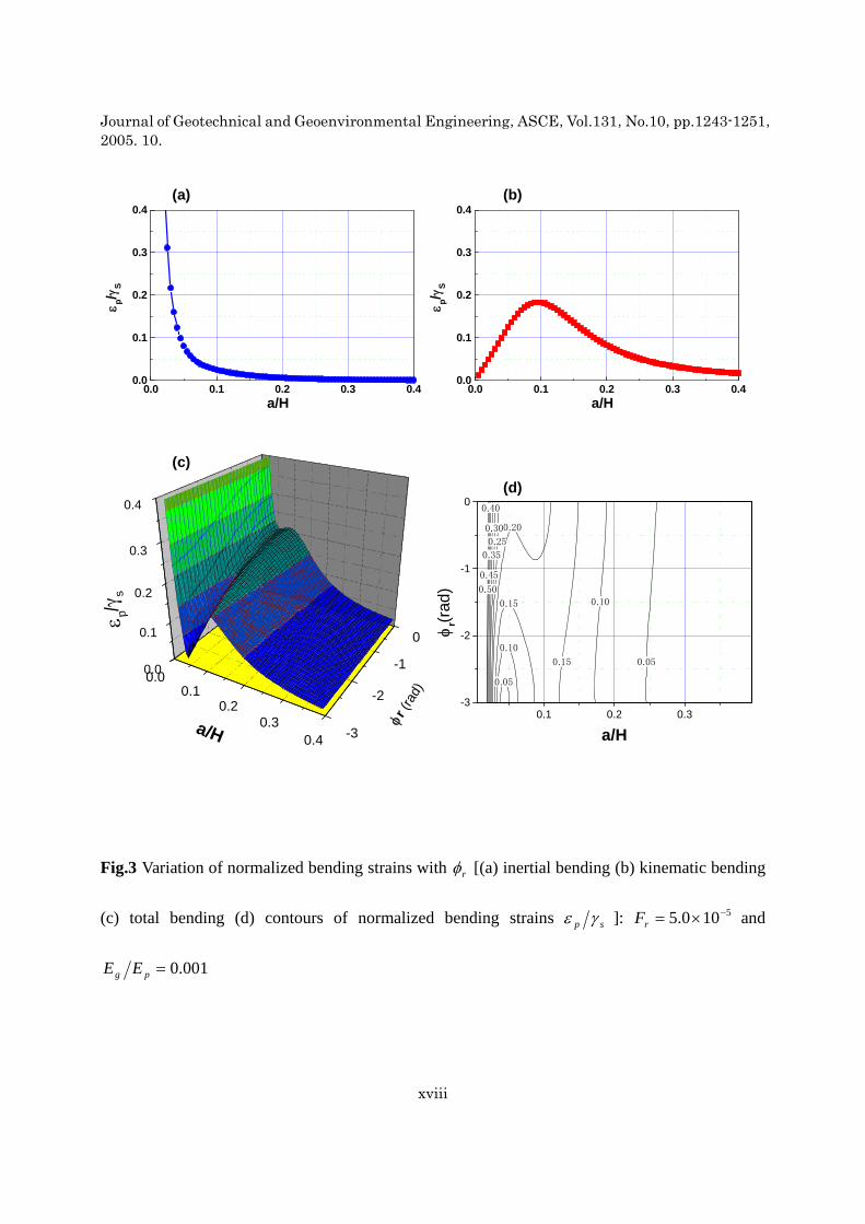
Fig. 3 shows the variations in normalized bending strains with different values of the phase lag
rφ for the factor 5100.5 −×=rF . Assumptions identical to those in Fig. 2 are made in Fig. 3 for the
non-dimensional parameters pg EE , bg EE , gp ρρ , the material damping gh , and the
Poisson’s ratios ν and bν . A single line is shown in each of Figs. 3(a) and 3(b) since each graph shows the absolute values of the normalized bending strains, which are independent of the phase lag rφ . Fig. 3(c) indicates that the normalized bending strains at the local minimum ( 05.0≈Ha ) gradually decrease as rφ decreases, while the slenderness ratio Ha minimizing the normalized strains do not substantially change with changes in rφ . Fig. 3 also indicates that when rφ becomes π− , the normalized bending strains converge to zero. The reason for this is that the normalized
bending strain due to the inertial bending becomes equal to that due to the kinematic bending, but in exactly the opposite direction. From a practical point of view, however, this may not be realistic
because the phase lag rφ probably converges to about 43π− in the case where 1≥gs TT , as
described by Murono and Nishimura (2000).
Fig. 4 shows the effects of the stiffness ratio pg EE upon the normalized bending strains for

Journal of Geotechnical and Geoenvironmental Engineering,ASCE,Vol.131,No.10,pp.1243-1251,2005. 10.
x
the factor 5100.5 −×=rF and the phase lag 0=rφ . The same assumptions in Fig. 2 and 3 are applied for the non-dimensional parameters in Fig. 4. Figs. 4(a) and 4(b) reveal that the normalized bending strain due to the inertial bending decreases over the entire range of Ha as the stiffness
ratio pg EE increases. In contrast, as pg EE increases, the normalized bending strain due to the
kinematic bending increases rapidly as the slenderness ratio Ha locally maximizing the normalized bending strain increases. As a result, a local minimum area is generated for large
pg EE (e.g., 310−≥ ), as shown in Figs. 4(c) and 4(d).
Fig. 5 shows the variations in normalized bending strains with various values of the
non-dimensional parameters bg EE , gh , gp ρρ , and ν for the factor 5100.5 −×=rF , the phase
lag 0=rφ , and 45.0=bν . Figs. 5(a), (b), (c) and (d) indicate that they have little effect upon the
normalized bending strains. Especially for bg EE , this result means that differences in the degree
of restraint of the rotational movement at the toe of the piles are almost negligible within the range
of bg EE shown in Fig. 5(a).
CRITERIA FOR DETERMINING THE OPTIMAL PILE RADIUS
Figs. 6 and 7 show criteria for easily estimating the slenderness ratio Ha that locally minimizes the normalized bending strains in soil-pile-structure systems where the kinematic interaction
dominates. These criteria are derived from Eq. 2 for 05.0=bg EE , 05.0=gh , 25.1=gp ρρ ,
and 45.0== bνν . These figures indicate that once the values of pg EE and rF , as well as the
phase lag rφ , are determined, the slenderness ratio Ha can be evaluated from curves indicating
the slenderness ratios Ha for various combinations of pg EE and rF . It is apparent that the
optimal pile radius is equal to the product of the corresponding Ha and the length of the pile H . In addition, these figures show the slenderness ratios Ha that locally maximize the normalized
bending strains for combinations of pg EE and rF . In these figures, a factor rP is also presented
as a ratio (expressed as a percentage) of the normalized bending strain at the local minimum to that at the local maximum, as shown in Fig. 6(b). If the factor rP is one-hundred percent, the
Journal of Geotechnical and Geoenvironmental Engineering,ASCE,Vol.131,No.10,pp.1243-1251,2005. 10.
xi
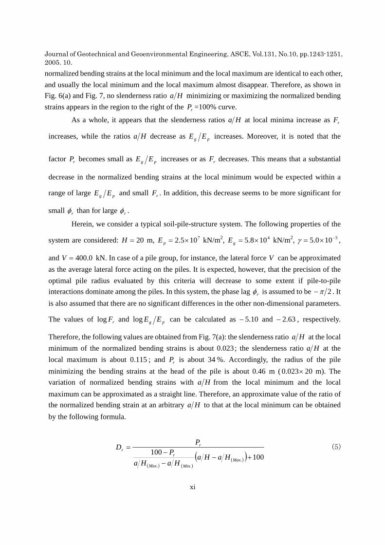
normalized bending strains at the local minimum and the local maximum are identical to each other, and usually the local minimum and the local maximum almost disappear. Therefore, as shown in Fig. 6(a) and Fig. 7, no slenderness ratio Ha minimizing or maximizing the normalized bending strains appears in the region to the right of the rP =100% curve.
As a whole, it appears that the slenderness ratios Ha at local minima increase as rF
increases, while the ratios Ha decrease as pg EE increases. Moreover, it is noted that the
factor rP becomes small as pg EE increases or as rF decreases. This means that a substantial
decrease in the normalized bending strains at the local minimum would be expected within a
range of large pg EE and small rF . In addition, this decrease seems to be more significant for
small rφ than for large rφ .
Herein, we consider a typical soil-pile-structure system. The following properties of the
system are considered: 20=H m, 7105.2 ×=pE kN/m2, 4108.5 ×=gE kN/m2, 3100.5 −×=γ ,
and 0.400=V kN. In case of a pile group, for instance, the lateral force V can be approximated as the average lateral force acting on the piles. It is expected, however, that the precision of the optimal pile radius evaluated by this criteria will decrease to some extent if pile-to-pile interactions dominate among the piles. In this system, the phase lag rφ is assumed to be 2π− . It is also assumed that there are no significant differences in the other non-dimensional parameters.
The values of rFlog and pg EElog can be calculated as 10.5− and 63.2− , respectively.
Therefore, the following values are obtained from Fig. 7(a): the slenderness ratio Ha at the local minimum of the normalized bending strains is about 023.0 ; the slenderness ratio Ha at the local maximum is about 115.0 ; and rP is about 34 %. Accordingly, the radius of the pile minimizing the bending strains at the head of the pile is about 46.0 m ( 20023.0 × m). The variation of normalized bending strains with Ha from the local minimum and the local maximum can be approximated as a straight line. Therefore, an approximate value of the ratio of the normalized bending strain at an arbitrary Ha to that at the local minimum can be obtained by the following formula.
( ) ( )( )( ) 100
100.
..
+−−−
=
MaxMinMax
r
rr
HaHaHaHa
PP
D (5)

Journal of Geotechnical and Geoenvironmental Engineering,ASCE,Vol.131,No.10,pp.1243-1251,2005. 10.
xii
If it is assumed that the radius a of the pile is, for instance, 8.0 m (the conventionally used value), the value of the ratio rD can be estimated to be about 74.0 . This implies that a 26 % decrease in the bending strain would be expected if the radius a were changed from 8.0 m to 46.0 m. In practical applications, therefore, Figs. 6 and 7, and also Eq. 5, may be useful for estimating the slenderness ratio Ha (radius a ) that minimizes the bending strains at the head of the piles, and for evaluating the effect of the slenderness ratio Ha upon the bending strains at arbitrary Ha using the factor rD .
CONCLUSIONS
In the present study, the following may be concluded:
1. In order to evaluate the characteristics of the bending strains of fixed-head piles embedded in a homogeneous soil in soil-pile-structure systems where the kinematic interaction dominates, closed form formulae are derived using three-dimensional wave propagation theory. A general expression for the closed form formulae can be obtained by normalizing the bending strain with respect to a mean shear strain of a soil stratum sγ . It is found that the normalized bending strains can be
expressed by the slenderness ratio Ha , the ratio of soil and pile stiffness pg EE , a factor rF ,
and a phase lag rφ , which represent dynamic characteristics of loading at the head of the piles and deformation of the soil.
2. The normalized bending strain due to the inertial bending decreases rapidly as the slenderness ratio Ha increases. On the one hand, the normalized bending strain due to the kinematic bending becomes zero when Ha is zero, whereas the normalized bending strain has a local maximum in a higher Ha region and gradually decreases beyond the local maximum. The variation of normalized bending strains with Ha indicates that a slenderness ratio Ha (radius) that minimizes the normalized bending strains at the head of the piles may appear, depending on the
values of pg EE , rF , and rφ . In addition, a local maximum of the normalized bending strain
mainly due to the kinematic bending may also appear in the higher Ha region. Parametric studies
indicate that the local minimum is more easily generated as rF becomes smaller or as pg EE
becomes larger. Moreover, the normalized bending strains at the local minimum gradually decreases as the phase lag rφ decreases.
3. Criteria are provided for easily estimating the pile radius that minimizes the normalized bending strains. It is noted that the factor rP , the ratio of the normalized bending strain at the local

Journal of Geotechnical and Geoenvironmental Engineering,ASCE,Vol.131,No.10,pp.1243-1251,2005. 10.
xiii
minimum and that at the local maximum, becomes small as pg EE increases or as rF decreases.
From these criteria, effects of the slenderness ratio Ha at the local minimum upon the normalized bending strains at arbitrary values of Ha can also be estimated using the factor rD .
REFERENCES
Gazetas, G. (1984). "Seismic response of end-bearing single piles." Soil Dyn. and Earth. Engrg., 3(2), 82-93.
Kagawa, T. and Kraft, L. M. (1981). "Lateral pile response during earthquakes." J. Geotech. Engrg. Div. ASCE, 107(12), 1713-1731.
Kavvadas, M. and Gazetas, G. (1993). "Kinematic seismic response and bending of free-head piles in layered soil." Geotechnique, 43(2), 207-222.
Kaynia, A. M. (1982). "Dynamic stiffness and seismic response of pile groups." Research Report R82-03,Dept. of Civil Engrg., MIT,Cambridge,MA.
Kaynia, A. M. and Mahzooni, S. (1996). "Forces in pile foundations under seismic loading." J. Engrg. Mech., ASCE, 122(1), 46-53.
Luo, X., Murono, Y., and Nishimura, A. (2002) "Verifying adequacy of the seismic deformation method by using real examples of earthquake damage." Soil Dyn. and Earth. Engrg., 22, 17-28.
Mizuno, H., Iiba, M., and Kitagawa, Y. (1984). "Shaking table testing of seismic building-pile-two- layered-soil interaction." Proc., 8th World Conf. on Earthquake Engrg.; Vol.3, Earthquake Engrg. Res. Inst. (EERI). San Francisco. Calif., 649-656.
Mizuno, H. (1987). "Pile damage during earthquakes in Japan." Dynamic response of Pile Foundations (ed. Nogami, T.), pp.53-78. New York: ASCE.
Murono, Y. and Nishimura, A. (2000). ''Evaluation of seismic force of pile foundation induced by inertial and kinematic interaction.'' Proc., 12th World Conf. on Earthquake Engrg.; New Zealand, No. 1496.
Mylonakis, G., Nikolaou, A.S., and Gazetas, G. (1997) "Soil-pile-bridge seismic interaction: kinematic and inertial effects. Part I: soft soil." Earthquake Engrg. & Struct. Dyn., 26, 337-359.
Nikolaou, S., Mylonakis, G., Gazetas, G., and Tazoh, T. (2001) "Kinematic pile bending during earthquakes: analysis and field measurements." Geotechnique, 51, 425-440.
Nogami, T. and Novak, M. (1977). ''Resistance of soil to a horizontally vibrating pile." Earthquake Engrg. & Struct. Dyn., 5, 249-261.
Ohira, A., Tazoh, T., Nakahi, S., and Shimizu, K. (1985). "Observation and analysis of earthquake response behavior of foundation piles in soft soil deposit." J. Struct. Mech. and Earthquake Engrg.,

Journal of Geotechnical and Geoenvironmental Engineering,ASCE,Vol.131,No.10,pp.1243-1251,2005. 10.
xiv
JSCE, 362/I-4, 417-426 (in Japanese).
Schnabel, P. B., Lysmar, J., and Seed, H. B. (1972). "SHAKE – a computer program for earthquake response analysis of horizontally layered sites." Report No. EERC72-12, EERC.
Tajimi, H. (1969). ''Dynamic analysis of a structure embedded in an elastic stratum.'' Proc. 4th World Conference on Earthquake Engrg., Tokyo, Japan, III (A-6), 53-69.
Takemiya, H. and Yamada, Y. (1981). "Layered soil-pile-structure interaction." Earthquake Engrg. & Struct. Dyn., 9, 437-452.
Tazoh, T., Wakahara, T., Shimizu, K., and Matsuzaki, M. (1988). "Effective motion of group pile foundations." Proc., 9th World Conf. on Earthquake Engrg.; Tokyo, 3, 587-592.
Veletsos, A. S. and Wei, Y. T. (1971). ''Lateral and rocking vibration of footings.'' J. Soil Mech. and Found. Div., ASCE, 97(9), 1227-1248.
Wolf, J. P. and Von Arx, G. A. (1982). ''Horizontally traveling waves in a group of piles taking pile-soil-pile interaction into account.'' Earthquake Engrg. & Struct. Dyn., 10, 225-237.
APPENDIX A. NOTATION
The following symbols are used in this paper:
a = radius of pile;
( ).MaxHa = slenderness ratio of pile at local maximum of bending strain;
( ).MinHa = slenderness ratio of pile at local minimum of bending strain;
bE = Young’s modulus of bedrock;
gE = Young’s modulus of soil;
pE = Young’s modulus of pile;
gh = damping constant of soil;
H = length of pile;
I = geometrical moment of inertia of pile;
1−=i = imaginary unit;
mK = modified Bessel function of the 2nd kind of order m;

Journal of Geotechnical and Geoenvironmental Engineering,ASCE,Vol.131,No.10,pp.1243-1251,2005. 10.
xv
rK = rotational stiffness at the toe of pile;
n = mode number of the Fourier series expanded in the vertical direction;
t = time;
gu = amplitude of horizontal excitation;
V = lateral load acting on the top of pile;
sbV = shear velocity of bedrock;
sγ = mean shear strain of soil stratum;
ν = Poisson’s ratio of soil;
bν = Poisson’s ratio of bedrock;
gρ = mass density of soil;
pρ = mass density of pile;
ω = circular frequency.

Journal of Geotechnical and Geoenvironmental Engineering,ASCE,Vol.131,No.10,pp.1243-1251,2005. 10.
xvi
Fig.1 Analytical soil-pile-structure model for a homogeneous soil medium and a fixed- head pile
supported by rotationally compliant bedrock: the system is excited by vertically-propagating
S-waves
Rotational Stiffness at the Toe of the Pile
Harmonic Excitation
θ
a2
z
H
tigeu ω
r
Fixed-Head Condition
z
V
rK

Journal of Geotechnical and Geoenvironmental Engineering,ASCE,Vol.131,No.10,pp.1243-1251,2005. 10.
xvii
0.00.1
0.20.3
0.4 -6
-5
-4
-3
0.0
0.1
0.2
0.3
0.4
ε p/γ
s
log(
Fr )
a/H
0.0 0.1 0.2 0.3 0.40.0
0.1
0.2
0.3
0.4
ε p/γ
S
a/H
0.00.1
0.20.3
0.4 -6
-5
-4
-3
0.0
0.1
0.2
0.3
0.4
ε p/γ
s
log(
Fr )
a/H
0.05
0.10
0.100.15
0.15
0.20
0.25
0.30
0.35
0.40
0.45
0.50
0.1 0.2 0.3-6
-5
-4
log(
Fr )
a/H
Fig.2 Variation of normalized bending strains with rF [(a) inertial bending (b) kinematic bending
(c) total bending (d) contours of normalized bending strains sp γε ]: 0=rφ and 001.0=pg EE
(a)
(b)
(c) (d)
Journal of Geotechnical and Geoenvironmental Engineering,ASCE,Vol.131,No.10,pp.1243-1251,2005. 10.
xviii
0.0 0.1 0.2 0.3 0.40.0
0.1
0.2
0.3
0.4
ε p/γ
S
a/H0.0 0.1 0.2 0.3 0.4
0.0
0.1
0.2
0.3
0.4
ε p/γ
S
a/H
0.00.1
0.20.3
0.4 -3
-2
-1
0
0.0
0.1
0.2
0.3
0.4
ε p/γ
s
φr (r
ad)
a/H
0.05
0.05
0.10
0.100.15
0.15
0.20
0.25
0.30
0.35
0.40
0.45
0.50
0.1 0.2 0.3-3
-2
-1
0
φr(r
ad)
a/H
Fig.3 Variation of normalized bending strains with rφ [(a) inertial bending (b) kinematic bending
(c) total bending (d) contours of normalized bending strains sp γε ]: 5100.5 −×=rF and
001.0=pg EE
(a) (b)
(c) (d)

Journal of Geotechnical and Geoenvironmental Engineering,ASCE,Vol.131,No.10,pp.1243-1251,2005. 10.
xix
0.00.1
0.20.3
0.4 -4
-3
-2
0.0
0.1
0.2
0.3
0.4
ε p/γ
s
log(
E g/E p
)
a/H
0.00.1
0.20.3
0.4 -4
-3
-2
0.0
0.1
0.2
0.3
0.4
ε p/γ
s
log(
E g/E p
)
a/H
0.00.1
0.20.3
0.4 -4
-3
-2
0.0
0.1
0.2
0.3
0.4
ε p/γ
s
log(
E g/E p
)
a/H
0.05
0.10
0.15
0.20
0.20
0.25
0.25
0.30
0.30
0.35
0.40
0.45
0.50
0.1 0.2 0.3-4
-3
-2
log(
Eg/E
p )
a/H
Fig.4 Variation of normalized bending strains with pg EE [(a) inertial bending (b) kinematic
bending (c) total bending (d) contours of normalized bending strains sp γε ]: 5100.5 −×=rF and
0=rφ
(a) (b)
(c) (d)

Journal of Geotechnical and Geoenvironmental Engineering,ASCE,Vol.131,No.10,pp.1243-1251,2005. 10.
xx
0.00.1
0.20.3
0.4 -2
-1
0
0.0
0.1
0.2
0.3
0.4
ε p/γ
s
log(
E g/E b
)
a/H
0.00.1
0.20.3
0.4 0.0
0.1
0.20.3
0.4
0.0
0.1
0.2
0.3
0.4
ε p/γ
s
h g
a/H
0.00.1
0.20.3
0.4 1
2
3
4
0.0
0.1
0.2
0.3
0.4
ε p/γ
s
ρ p/ρ g
a/H
0.00.1
0.20.3
0.4 0.2
0.3
0.4
0.5
0.0
0.1
0.2
0.3
0.4
ε p/γ
s
ν
a/H
Fig.5 Variation of normalized bending strains with various parameters [(a) bg EE (b) gh
(c) gp ρρ (d)ν ]: 5100.5 −×=rF and 0=rφ
(a) (b)
(c) (d)

Journal of Geotechnical and Geoenvironmental Engineering,ASCE,Vol.131,No.10,pp.1243-1251,2005. 10.
xxi
Fig.6 Criteria for evaluating slenderness ratios Ha that minimizes normalized bending strains at
the head of a fixed-head pile with pg EE and rF when kinematic interaction dominates in
soil-pile- structure systems [(a) criteria for 1≤gs TT ( 0=rφ ) (b) definition of corresponding
factors in Ha - sp γε relations]
-6.0 -5.5 -5.0 -4.5 -4.0 -3.5 -3.0-4.0
-3.5
-3.0
-2.5
-2.00.150.140.130.12
0.11
0.10
0.09
0.08
0.07
a/H(Max.)=0.06
log
(Eg/E
p)
0.100.090.080.070.060.050.040.030.02a/H(Min.)=0.01
100%
90%80
%70%60
%50%
40%
30%
P r=20
%
log Fr
a/H
εp/γs
a/H(Max.)
εM
εN
( )%100×=N
MrP
εε
a/H(Min.)
( )%100=rP
(a) (b)

Journal of Geotechnical and Geoenvironmental Engineering,ASCE,Vol.131,No.10,pp.1243-1251,2005. 10.
xxii
Fig.7 Criteria for evaluating slenderness ratios Ha that minimizes normalized bending strains at
the head of a fixed-head pile with pg EE and rF when kinematic interaction dominates in
soil-pile- structure systems [(a) for 1≈gs TT ( 2πφ −=r ) (b)for 1≥gs TT ( 43πφ −=r )]
-6.0 -5.5 -5.0 -4.5 -4.0 -3.5 -3.0-4.0
-3.5
-3.0
-2.5
-2.00.150.140.130.12
0.11
0.10
0.09
0.08
0.07
a/H(Max.)=0.06
log
(Eg/E
p)
80%
0.090.080.070.060.050.040.030.02a/H(Min.)=0.01
100%
90%
70%60
%50%40
%30
%P r=
20%
log Fr
(a)
-6.0 -5.5 -5.0 -4.5 -4.0 -3.5 -3.0-4.0
-3.5
-3.0
-2.5
-2.00.150.140.13
0.120.11
0.10
0.09
0.08
0.07
a/H(Max.)=0.06
log
(Eg/E
p)
80%
0.090.080.070.060.050.040.030.02a/H(Min.)=0.01
100%90%70
%60%50
%40%
30%
20%
P r=10
%
log Fr
(b)